1
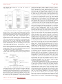
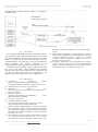
International Journal on Recent and Innovation Trends in Computing and Communication
Volume: 3 Issue: 5
ISSN: 2321-8169
2558 - 2561
_______________________________________________________________________________________________
Implementation of MPU for a Safe FreeRTOS Frame-work
Bhavesh Shah
Babu Krishnamurthy
Embedded System Design
GTU PG School, Gujarat Technological University
Ahmedabad, India.
[email protected]
Teaching faculty Embedded System Design
CDAC - ACTS
Pune, India
[email protected]
Abstract - In the embedded world, there are some types of applications which needed to perform with higher accuracy, with safety
of data and application, robustness, with a very small footprint and very high performance. This all features are mostly preferred
in most of Real Time Operating System (RTOS). But in RTOS itself, there are some problems like data corruption due to some
bugs in some part of the code. Due to any illegal access to any part/peripherals/data could cause crash of the whole system. For
such kind of applications like safety critical applications in which such things needed to be taken for not letting the system to
crash there is a need of having OS, which will provide all the features which we have just discussed. Here in this paper, we
propose a way of getting our desired performance from an open source OS FreeRTOS with its IO framework and running those in
MPU mode. With the help of some Memory Protection Unit isolation for user space and system specs, different tasks from each
other and system space can be achieved. It can achieve by providing MPU functionality in port layer and isolating different tasks
data. And provide a protection to FreeRTOS.
Keywords- FreeROTS, Safety critical application, Memory Protection Unit (MPU).
__________________________________________________*****_________________________________________________
I.
INTRODUCTION
Certain embedded applications can be called as safety
critical application like flight critical aircraft control, aerospace,
nuclear, automotive, medical areas. These applications can be
explained as that while in the process it is not allowed to have
any kind of error, latency more than a particular limit. It is such
a critical application that if any kind of problem comes in any
stages of its running time it could cause a lot of damage to lives
and money. Such kind of faults comes in cases like a very small
fault can create some error or delay and then that leads to
failure. Due to the failure of such a small part of the system can
cause faults in another part of systems which depend on that
part. It leads to the failure of that part of the system too, then
could be whole system failure [1].
FreeRTOS [2] is an open source RTOS, but for applying
this OS for such safety critical applications, it is not suitable
because its functional model, subjected to a full HAZOP, it has
weakness within the functional modal and API, and not having
safety requirements. [3]. Now, as we see earlier that system
failure starts from the failure of a small part of a system can
cause avalanches of faults and failure in the system. To avoid
that we can provide some permission to access amount of
memory for certain part of the code. Which can be provided
using Memory Protection Unit (MPU).
The MPU is a part of the processor, which defines which
part of memory to access and which part to not. If MPU is used
in such application running on FreeRTOS. It would provide
safety from those cascaded fault-error-failure as parts of
systems would be isolated with each other.
Yamada et al. [8] say that Memory Protection using
Memory Management Unit (MMU) can have more latency due
to more number of page tables and the low level bit protection.
And for the Real time application they suggest MPU should be
used.
SafeRTOS is the safety critical OS, which is licensed and
not open source. Which also provide software of different
Safety Integrity Levels to co-exist a Single Build of code
without unwanted mutual interface with the use of MPU [4].
Stecklina et al. [9] say that with the use of MPU it enforces
a secure isolation of individual activates. And also MPU
support is suitable number of activities and memory segments
and can handle an access control without a performance loss in
most of the cases.
Khan et al. [10] talk about MPU in the automotive
industries in electronic control unit (ECU). As in the ECU there
plenty numbers of electronically controlled unit which are
produced sparely and brought together to create a complete
system. And at the time of adding some extra add-on software
with the main ECU application. It can be easily added if MPU
is properly implemented in those applications.
Greiner et al. [11] propose that multiple native software
stacks are thus bound to share the resources without protection
between them. NoC-MPU is a Memory Protection Unit
allowing supporting the secure and flexible co-hosting of
multiple native software stacks running in multiple protection
domains, on any shared memory MP-SoC using a NoC.
In such cases and implementation done till now we can
make a conclusion that for the safety of the application
isolation of different parts of the system. And that can be
providing memory protection to those parts. So making,
creating a safe FreeRTOS framework we need to create it in
Memory Protection Unit mode.
II.
FREERTOS+IO FRAMW WORK
FreeRTOS+IO framework is used for accessing peripheral.
Figure 1 shows the layered architecture of the FreeRTOS+IO
framework. When an application asks for any access to any
peripheral while using FreeRTOS APIs then the first it goes the
FreeRTOS+IO layer where they identify the which peripheral
is being asked by the application layer to be accessed. Then it
goes to peripheral driver library which would have specific
access functions like open, read, write and ioctl with the help of
FreeRTOS kernel. In those functions, it uses the CMSIS
Driver’s functionality for accessing particular functionality of
2558
IJRITCC | May 2015, Available @ http://www.ijritcc.org
_______________________________________________________________________________________
International Journal on Recent and Innovation Trends in Computing and Communication
Volume: 3 Issue: 5
ISSN: 2321-8169
2558 - 2561
_______________________________________________________________________________________________
that peripheral. [6] Which directly goes to Devices available on
the microcontroller and access those devices. On other side
FreeRTOS kernel interfaces the Processor Peripheral with the
help of a FreeRTOS HAL+BSP layer with CMSIS Library with
its core peripheral functionality.
the ready queue to run the TCB would be loaded in
pxCurrentTCB and at the time of context switch the 4 regions
from xMPUSettings including 1 stack region and 3 memories
accessed regions for that task would be loaded in those 4
configurable regions of MPU registers. When another task is
scheduled than same process take in place and that task’s 4
regions would take place in those last 4 MPU configurable
regions.
After enabling the MPU rest of the memory space which is
not being included in any memory region is known as
background memory regions. MPU provides two access
permission over here that all the background region could be
privileged access only that could be no access allowed [5].
Figure 2 and Figure 3 shows the memory regions created at
starting of the scheduler, and when different tasks are being
scheduled.
Background region is important in that way the task which
is scheduled at a time will be bound to those 8 regions only. In
the case of privileged background the task is in unprivileged
mode, so it would not allow to access memory region except
then those 8 regions. While talking about no background
access the background region would not be allowed to access
anything except 8 regions. Figure 3 has been discussed further.
Figure 1: FreeRTOS+IO Framework
With the help of an IO layer FreeRTOS kernel creates a
handler which is the object of structure Peripheral_Control_t
which would have pointers to functions of reading, writing,
ioctl and other peripheral related members. This object is being
created dynamically and stored in the heap memory area.
FreeRTOS+IO APIs with the help of such handler of the
peripherals they can communicate with peripheral devices.
Here we use LPC 1769 Embedded Artist Baseboard for
implementations of safe FreeRTOS implementation.
III.
MEMORY PROTECTION UNIT (MPU)
Processor who has MPU here in our case Cortex M3 works
normally if the MPU is not being activated. But if MPU is
activated, then the processor can access only those memory
regions which are mentioned in MPU registers as per its
access permissions. If the memory access violates any access
permission, then the Memory Management faults will be
called. Here in Cortex M3 only 8 regions are allowed to create.
Regions are allowed to modify at run time. And if a part of
memory is there in two different regions, then the memory
access permission would be as per the latest memory region’s
access permissions [5].
IV.
FREERTOS IN MPU MODE
FreeRTOS distribute its workload in different tasks.
FreeRTOS in MPU mode at the time of starting the scheduler
the basic MPU regions are being set up. 4 regions out of 8 will
be set up at the time of starting of the scheduler. And those are
privileged function region, the code reads only region,
privileged data region, and full accessed peripheral region.
Those regions will be the permanent region after this point of
time, because it would be same for all the tasks. Then
remaining 4 regions would be like the configurable MPU
regions for tasks. When a particular task is being taken from
Figure 2: Memory map for background privileged access only
Here MPURNR indicate the number of the memory region
stored in MPU registers.
V.
FREERTOS+IO IN MPU MODE
We will talk for the both background cases separately. First,
we will talk about background privileged access only then we
will talk about background access not allowed. In the
FreeRTOS+IO framework most of the hardware setup is being
done in the main( ) area only. Now at this time MPU is not
being enabled. Over here handler for particular peripheral is
being created with the use of FreeRTOS+IO APIs. Then after
creating a number of tasks in restricted mode using
xTaskCreateRestricted( ).
With appropriate priority and required handlers of the
peripherals as task’s parameters and memory regions to be
allowed to be accessed by that task. These all tasks are created
to run in unprivileged mode only or sometime after getting
2559
IJRITCC | May 2015, Available @ http://www.ijritcc.org
_______________________________________________________________________________________
International Journal on Recent and Innovation Trends in Computing and Communication
Volume: 3 Issue: 5
ISSN: 2321-8169
2558 - 2561
_______________________________________________________________________________________________
some global data needed for the task the switch to
unprivileged mode.
Figure 3: Memory map for background access not allowed
At the point when the task is brought to the unprivileged
mode its start, its real work they start communicating with the
peripherals. This is the time when tasks are running after start
of the scheduler and after setting up those default four memory
region and enabling MPU with a background region in
privileged access only permits. Here the handler memory
regions which are taken from heap pool. That part of memory
is now in privileged access mode if there is not included in any
region. In our case it is not. In this case, that task would not
allowed to access that handler of peripheral. This is happening
because FreeRTOS+IO APIs are not jumping into the system
space to do its functionality.
To solve this we include FreeRTOS+IO’s APIs in
mpu_wrappers.h and make sure that those APIs functionalities
execute in privileged mode only. By doing this we are adding
FreeRTOS+IO’s APIs as a part of FreeRTOS kernel. This can
be explained nicely as shown in the Figure 4.
So here we would able to douse FreeRTOS+IO framework
in MPU mode with a background region in privileged access
only case.
Figure 4: FreeRTOS_write in MPU mode
Now in the case of background region access not allowed
everything in main( ) is same as in above case. But at the time
of starting scheduler when the MPU is being set up and
enabled over there background regions is given permissions as
access not allowed. Now, after this point region excluded from
those four basic regions would not be allowed to access. Only
those regions which are being modified after this would have
the access as per their permissions. At this point the problem
comes that Main Stack Pointer (MSP) is now in no access
permission and with that all the data and the handlers for
devices distributed on whole SRAM would be now in no
access area. So neither privileged nor unprivileged code area
can access that part. And the data would be in very large
amount so it is not possible to create a separate memory region
for those data. So for the solution of this problem here we
create whole SRAM in privileged access permission in stand
of a region of privileged data’s region. As whole SRAM
would become memory space with privileged access only
normal task in our case which all are in unprivileged mode
would not be allowed to access those memory regions unless
that particular data’s regions as one of the memory region of
the 3 memory region allowed to be accessed by that task.
Till now we are able to create system space which would
include the processor peripheral, and data stored in SRAM.
This all part would be accessed by the function or code which
would be in privileged mode. And another part is in user space
which is doing communication work and our required
functionality which is distributed in the form of different tasks.
These all tasks have their own memory regions to access. And
they cannot access anything else than that. As shown in figure
2 and 3 we can have an idea, how would be those memory
regions for tasks. There is no fixed that there would be 8
regions of memory every time for every task. It can be less
than that as per the requirements of the task. First four regions
would be there every time, but last 4 regions would be
changing as per the requirement of current task or any handler
is running at that time. And talking about the peripheral usage,
all the peripheral handlers would be in the area of privileged
access only. So any task just can’t access those handlers as
they all are in unprivileged mode, unless if we don’t give the
handler to be accessed by that particular task. If a task is
designed to do certain functionality so with the help of the
handler object created at the time of opening that peripheral is
passed to that task. That handler is itself is the address of the
object created for that peripheral. Now if a task is not passed
to that particular handler which that task want to access during
its execution. If a task is allowed to access a handler of a
particular peripheral so it mean it is allowed to access that
particular drivers of that peripheral. If a developer tries to
access peripheral in a task which is not allowed at the time of
development. It would not be possible. Thus, this system
would become more robust. The isolation for a particular task
from another task and with peripheral drivers it can be
explained from the Figure 5. Here a task 1 is allowed to access
a particular peripheral so it can access it with the mode
switching mechanism as explained earlier.
So after such implementation if any part of system fails due
to error in any of faults. They will not make any kind of effect
on other part of systems as all the part of systems would be
isolated from each other. It also provide the safety at the
development level of the system. As by the mistake of the
coder some data is been tried to be used by some part of the
system which that part is not allowed to access then the system
would create Memory Management fault at the debugging
time. So it also provides robustness to the system. Here we
provide the rules to different parts of the system by giving
them access permission and provide them isolation from each
other and create an environment where different safety
integrity levels to co-exist on a single build of code without
2560
IJRITCC | May 2015, Available @ http://www.ijritcc.org
_______________________________________________________________________________________
International Journal on Recent and Innovation Trends in Computing and Communication
Volume: 3 Issue: 5
ISSN: 2321-8169
2558 - 2561
_______________________________________________________________________________________________
unwanted mutual interface the use of MPU as we talked in
introduction part.
Figure 5: task 1's Isolation for IO
VI.
CONCLUSION
This latter describe Memory Protection Unit alone itself, it
gives protection from using unwanted memory access. But
now after using MPU in FreeRTOS+IO framework with MPU
mode, we can say that we can have protection for not just
unwonted memory access but also we can have protection in
using peripherals also. Devices connected to the
microcontroller can also be protected from unwanted access.
FreeRTOS is freely available, easy to use RTOS. For using
this OS for some safety critical application the approach
mention in this latter can be helpful. For more safety this OS
can also be scaled down as per the requirement of the
application and can be made safer as per the application.
8th IEEE International Symposium. 19-21 June 2013.Pages :
225-231
[9] Akram Khan,AchimSchäfer, and MarkusZetlmeisl “Efficient
Memory-Protected Integration of Add-On Software Subsystems
in Small Embedded Automotive Applications”. Industrial
Informatics, IEEE Transactions on (Volume: 3, Issue: 1), 12
February 2007, Pages: 45-50.
[10] JoelPorquet, Alain Greiner, and ChristianSchwarz “NoC-MPU:
a secure architecture for flexible co-hosting on shared memory
MPSoCs”. Design, Automation and Test in Europe Conference
and Exhibition ,2011, 14-18 March 2011, Pages: 1-4.
VII. REFERENCES
[1]
[2]
[3]
[4]
[5]
[6]
[7]
[8]
“Architecture
of
safety-critical
systems”,
http://www.embedded.com/design/prototyping-anddevelopment/4006464/Architecture-of-safety-critical-systems
"FreeRTOS official site", http://www.freertos.org
“SafeRTOS
officail
site”,
http://www.highintegritysystems.com/safertos/upgrade-fromfreertos-to-safertos/
SafeRTOS_Datasheet,
Upgrading_from_FreeRTOS_to0_SafeRTOS_v3
CortexM3Technical Reference Manual.
LPC176x/5x User manual
“ CMSIS introduction by ARM ”,
http://www.arm.com/products/processors/cortex-m/cortexmicrocontroller-software-interface-standard.php
Shimpei Yamada, YukikazuNakamoto, “Protection Mechanism
in Privileged Memory Space for Embedded Systems, Real-Time
OS” Distributed Computing Systems Workshops (ICDCSW),
2014 IEEE 34th International Conference onJune 30 2014-July 3
2014. Pages: 161 – 166.
Oliver Stecklina, Peter Langendoerfer, Hannes Menzel, “Design
of a tailor-made Memory Protection Unit for Low Power
Microcontrollers”.Industrial Embedded Systems (SIES), 2013
2561
IJRITCC | May 2015, Available @ http://www.ijritcc.org
_______________________________________________________________________________________