1
GDAŃSK
versa_p_en 10/12
VERSA
Firmware version 1.03
Alarm Control Panels
PROGRAMMING
The SATEL's goal is to continually upgrade the quality of its products, which may result in
alterations of their technical specifications and firmware. The current information on
the introduced modifications is available on our website.
Please visit us at:
http://www.satel.eu
Changes made to the firmware version 1.03
Service mode
Changed names of service functions:
– 3. ACU-100 to 3. WIRELESS MOD.
– 4. ACU-100 zones to 4. WIRELSS.ZONES.
Expansion
modules
New option for ACU-100 controller: HIGHER SENSITIVITY FOR JAMMING
DETECTION.
Support for new modules:
− INT-RX-S – 433 MHz keyfobs receiver expansion module,
− VERSA-MCU – 433 MHz wireless system controller,
− ACU-250 – ABAX wireless system controller.
2
Programming Manual
SATEL
CONTENTS
1.
Control Panel Firmware Replacement .......................................................................... 4
1.1
1.2
2.
Programming .................................................................................................................. 5
2.1
2.1.1
2.1.2
2.1.3
2.1.4
2.1.5
2.1.6
2.1.7
2.1.8
2.1.9
2.2
2.2.1
2.2.2
2.2.3
2.2.4
2.2.5
2.2.6
2.2.7
2.2.8
2.2.9
3.
Starting the service mode ................................................................................................................ 5
Starting the service mode "from pins" ............................................................................................. 5
Access to functions by using arrow keys ......................................................................................... 6
Access to functions by using numerical shortcuts ........................................................................... 6
"Step by step" programming method ............................................................................................... 7
Service mode menu ......................................................................................................................... 7
Entering data by means of the LCD keypad .................................................................................. 12
Selection from the single-choice list............................................................................................ 12
Selection from the multiple-choice list......................................................................................... 12
Entering decimal values .............................................................................................................. 12
Entering hexadecimal values ...................................................................................................... 12
Programming telephone numbers ............................................................................................... 12
Entering names ........................................................................................................................... 13
Entering data by means of the LED keypad .................................................................................. 14
Selection from the single-choice list............................................................................................ 14
Selection from the multiple-choice list......................................................................................... 14
Entering decimal values .............................................................................................................. 14
Entering hexadecimal values ...................................................................................................... 16
Programming telephone numbers ............................................................................................... 16
Exiting the service mode................................................................................................................ 17
DLOADX program.................................................................................................................. 17
Main menu of the DLOADX program............................................................................................... 17
Changing the program access code .............................................................................................. 19
Parameters related to programming by means of the DLOADX program....................................... 19
Identifiers ..................................................................................................................................... 20
Telephone communication parameters....................................................................................... 20
Parameters of communication via Ethernet (TCP/IP) network ................................................... 20
Starting local programming without verification of identifiers ........................................................ 21
Starting local programming with verification of identifiers ............................................................. 21
Starting local programming "from pins" ......................................................................................... 21
Finishing local programming .......................................................................................................... 22
Starting remote programming via modem ..................................................................................... 22
Configuring settings of modem connected to computer ............................................................. 22
Initiating connection from the DLOADX program .......................................................................... 22
Initiating connection from the DLOADX program, but with the control panel calling back and
establishing connection ............................................................................................................... 23
Initiating connection by the control panel .................................................................................... 23
Starting remote programming via Ethernet network ...................................................................... 24
Initiating connection from the DLOADX program .......................................................................... 24
Initiating a connection by the control panel ................................................................................. 24
Global options ...................................................................................................................... 25
Global times ......................................................................................................................... 28
Partitions ....................................................................................................................... 29
4.1
5.
Keypad ................................................................................................................................... 5
Global Parameters ........................................................................................................ 25
3.1
3.2
4.
Firmware replacement using the service function.................................................................. 4
Firmware replacement without entering the service mode .................................................... 4
Partition parameters............................................................................................................. 29
Zones ............................................................................................................................. 31
5.1
5.1.1
5.1.2
5.2
5.3
Numeration of system zones ............................................................................................... 32
Hardwired zones ............................................................................................................................ 32
Wireless zones .............................................................................................................................. 32
End of line resistors ............................................................................................................. 32
Zone parameters.................................................................................................................. 33
SATEL
5.4
5.5
6.
6.1.1
6.1.2
6.2
6.3
6.4
6.5
Zone types............................................................................................................................ 35
Zone options......................................................................................................................... 36
Numeration of outputs in the system .................................................................................... 39
Hardwired outputs ..........................................................................................................................39
Wireless outputs .............................................................................................................................39
Output functions ................................................................................................................... 39
Output parameters ............................................................................................................... 40
Output options ...................................................................................................................... 41
Quick control of outputs........................................................................................................ 43
Programming Keypads and Expanders ...................................................................... 44
7.1
7.2
7.3
7.3.1
7.3.2
7.3.3
7.3.4
7.3.5
7.3.6
7.3.7
7.4
7.4.1
7.4.2
7.4.3
7.4.4
7.5
8.
9.
3
Outputs .......................................................................................................................... 38
6.1
7.
VERSA
Keypad ................................................................................................................................. 45
ETHM-1 Ethernet module..................................................................................................... 47
ABAX wireless system controller.......................................................................................... 48
Parameters of ABAX system wireless devices...............................................................................48
ABAX wireless detectors – general programming rules .................................................................50
Wireless sirens – general rules of programming ............................................................................51
Wireless expanders of hardwired zones and outputs – general rules of programming .................52
230 V AC wireless controllers – general rules of programming .....................................................52
Configuration of ABAX wireless devices by means of the DLOADX program .................................53
Configuration of ABAX wireless devices by means of the LCD keypad.........................................55
433 MHz wireless system controller ..................................................................................... 58
Parameters of 433 MHz wireless detectors....................................................................................58
Configuration of 433 MHz wireless detectors using the DLOADX program.....................................58
Configuration of 433 MHz wireless detectors using LCD keypad ..................................................59
433 MHz wireless detectors and zone programming .....................................................................59
Proximity card arm/disarm device ........................................................................................ 59
Timers ............................................................................................................................ 60
Reporting ....................................................................................................................... 61
9.1
9.2
9.3
9.3.1
9.3.2
Reporting parameters and options ....................................................................................... 62
Event codes.......................................................................................................................... 64
Starting the reporting ............................................................................................................ 64
Telephone reporting .......................................................................................................................65
Reporting via Ethernet network ......................................................................................................65
10. Messaging ..................................................................................................................... 66
10.1
10.2
10.3
10.4
Messaging parameters and options ..................................................................................... 66
Event assignment ................................................................................................................. 67
SMS/Pager messages.......................................................................................................... 67
Starting the messaging......................................................................................................... 67
11. User Schedules ............................................................................................................. 68
11.1
11.2
11.3
Parameters of the user schedule ......................................................................................... 68
Functions assigned to keyfob buttons .................................................................................. 70
Confirmation on LEDs in the APT-100 keyfob...................................................................... 72
12. Compliance with EN 50131 Standard Requirements for Grade 2 ................................ 72
13. History of Changes to the Manual Content ................................................................ 73
4
Programming Manual
SATEL
1. Control Panel Firmware Replacement
This manual applies to the control panels with firmware version 1.03. If a newer version of
firmware is available on our www.satel.eu website, an update of the control panel firmware
is possible. For this purpose, the control panel RS-232 (TTL) port (RJ type socket) should be
connected to the computer COM port (DB9 type socket) with the SATEL made cable which is
included in the DB9FC/RJ-KPL set.
Notes:
• From the moment of establishing communication between the control panel and the
firmware updating program, the control panel will not execute its normal functions until the
firmware replacement procedure is completed.
• If, for whatever reason, the firmware replacement procedure is abruptly terminated (e.g.
because of power failure) and, as a result, the control panel firmware gets damaged, the
control panel will not start normally, but will be waiting for the firmware replacement to
begin.
1.1
Firmware replacement using the service function
1. Enter the service code on the keypad (by default: 12345) and press the
key.
2. Press in turn the
keys to start the service mode.
3. Press in turn the
keys (the STARTER function will start). The "Run
updating program on PC..." message will be displayed. The control panel will be waiting
until communication with the firmware updating program is established (press the
key to terminate operation of the STARTER function).
4. Start the control panel firmware update program in the computer.
5. Click on the
button.
6. A window will open where you should indicate the computer COM port to which the
control panel is connected and press the "OK" button. The firmware updating program will
establish communication with the control panel.
7. Information will be displayed showing the version of firmware installed on the control
panel and available in a file (version, compilation date, language) and a window will
open, prompting whether you would like to continue. If the firmware is to be replaced,
press "Yes" to begin the control panel firmware replacement.
1.2
Firmware replacement without entering the service mode
1. Start the control panel firmware update program on the computer.
2. Click on the
button.
3. A window will open where you should indicate the computer COM port to which the
control panel is connected and select the RESTART field.
4. Power down the control panel (first switch off the 230 V AC circuit to which the control
panel transformer is connected, and then the battery).
5. Power up the control panel (first switch on the battery, and then the 230 V AC circuit to
which the control panel transformer is connected).
6. Information will be displayed showing the version of firmware installed on the control
panel and available in a file (version, compilation date, language) and a window will open
prompting whether you would like to continue. If the firmware is to be replaced, press
SATEL
VERSA
5
"Yes" (the control panel will only wait 10 seconds after power-up for the firmware
replacement to begin). Then the replacement of control panel firmware will start.
2. Programming
The alarm control panel may be configured for operation by using the keypad (locally) or
the computer with the DLOADX program installed (locally and remotely).
2.1
Keypad
Programming is only possible when the control panel is accessible to the installer. By default,
0. SERVICE
the PERMANENT SERVICE ACCESS option is enabled ([code]
5. SERV. ACCESS). After the installation is completed, the user having the
DOWNLOAD/SERVICE right can disable the PERMANENT SERVICE ACCESS option and define
each time the duration of service access to the control panel ([code]
0. SERVICE
6. ACCESS TIME).
Programming the control panel from keypad is carried out by using the functions grouped in
the service mode menu. Access to the menu, submenus and particular functions is facilitated
by numerical shortcuts. In case of the LED keypad, programming is subject to some
limitations (e.g. entering names is impossible). SATEL recommends that the LCD keypad
be used for programming the control panel.
The service mode is indicated on the keypads by means of the blue
LED. The
LED is
lit on the keypad in which the service function menu is available, while it is blinking on all the
other keypads connected to the control panel. The service mode may also be signaled
acoustically, after the corresponding option is enabled. Additional information is provided by
LED, which is:
the
– blinking during navigation throughout the menu and submenus;
– lit when any service function is running.
When in the service mode, the alarm system signals no alarms.
2.1.1
Starting the service mode
1. Enter the service code (by default: 12345) and press the
key.
2. Press in turn the
keys to start the service mode.
2.1.2
Starting the service mode "from pins"
If entering the service mode in the normal way is impossible, you can use the emergency
hardware procedure, so-called starting "from pins".
1. Power down the control panel (first, switch off power in the 230 V AC circuit, to which the
control panel transformer is connected, and then disconnect the battery).
2. Place a jumper across the RESET pins on the control panel mainboard.
3. Power up the control panel (first, connect the battery, and then switch on power supply in
the 230 V AC circuit, to which the control panel transformer is connected).
4. Wait a few seconds and remove the jumper from the RESET pins.
5. On the keypad with the lowest address, the
LED will light up and the
LED will start
blinking, indicating that the service menu is available on the keypad (in case of the LCD
keypad, the menu will be displayed). On the other keypads, the
LEDs will start
blinking.
6
Programming Manual
SATEL
If the SERVICE MODE FROM RESET PINS option is disabled in the control panel (see:
Section GLOBAL OPTIONS) then, depending on the type of keypad in which the
lowest address is set:
– LCD: the
,
and
LEDs of the second partition will be lit, and the
message "Restore factory settings ? 1=Yes" will come up on the display;
– LED: the
and
LEDs of the second partition will be lit and the
LED
will be blinking rapidly.
Pressing the key with digit 1 will reset the control panel to its factory settings,
but will enable entering the service mode.
2.1.3
Access to functions by using arrow keys
This way of starting the function is only available in the LCD keypad.
1. Use the
and
keys to find the required submenu (the shape of submenu
cursor is: ).
2. Press the
or
key to enter the submenu (use the
key to return to the
key to return to the main menu).
previous menu/submenus, and the
3. Repeat the steps described in 1 and 2 until you find the required function (the shape of
function indicating cursor is: ). Press the
or
key to start the function.
key and return to the submenu.
4. When entering new settings, accept them using the
Press the
key to cancel entering the new settings and return to the submenu.
2.1.4
Access to functions by using numerical shortcuts
This way of starting the function is available in all types of keypads supported by the VERSA
control panels. All submenus and functions are numbered. In order to enter a submenu, just
press the key with number corresponding to the submenu number. In order to start a
function, press the key with number corresponding to the function number, and then the
key. You can quickly start the selected function by entering at once a sequence of
some digits (corresponding to the consecutive submenu numbers and the function number)
and confirming them by pressing the
key.
For example, to start the expander identification function, first enter the service mode and
then press in turn the
keys, where:
- enter 2. HARDWARE submenu;
- enter 1. KPDS & EXPS. submenu;
- start 1. IDENTIFICAT function.
In the LCD keypad, use the
key to return from a submenu to the main menu or from a
function to a submenu, and use the
key to return from a submenu to the previous
menu/submenu.
In the LED keypad, use the
key to return to the main menu.
Notes:
• When using the numerical shortcuts, remember that the sequence of digits which starts
a function e.g. from the service mode main menu level will not start the same function
from the submenu level.
• In the LCD keypad, the shape of the submenu cursor is: , and that of the function
indicating cursor is : .
SATEL
2.1.5
VERSA
7
"Step by step" programming method
Some components of the system (e.g. zones, outputs, expanders, wireless devices, event
codes for reporting, etc.) should be programmed using the "step by step" method. When the
function is called up and the component to be configured selected from the list, the first
parameter available for programming will be displayed. Irrespective of whether or not it will be
modified, pressing the
key will take you automatically to programming the next
parameter (the changes will be saved). After all available parameters are configured, return
to the submenu follows in the LCD keypad, and to the main menu in the LED keypad. The
key (you will return to the
programming can be terminated at any moment by using the
submenu). The
and
LEDs of the first and second partitions show the programming
step number in binary mode (see: page 15 Table 4).
2.1.6
Service mode menu
Shown in square brackets are sequences which enable calling up a particular submenu or
starting a particular function from the main menu level.
0. SrvMod config
[00#] 0. Serv.Mode end
[01#] 1. VERSA id.
[02#] 2. DloadX id.
[04#] 4. DloadX tel.
[06#] 6. SrvMod opt.
[07#] 7. Restore all
[08#] 8. Default usr.
[09#] 9. STARTER
1. Partitions
[11#] 1. Part. 1 zones
[12#] 2. Part. 2 zones
[13]
3. Part. 1 times
[131#] 1. Exit delay
[132#] 2. Entry delay
[133#] 3. Warning
[134#] 4. Verification
[135#] 5. Autoarm delay
[136#] 6. A-arm defer
[14]
4. Part. 2 times
[141#] 1. Exit delay
[142#] 2. Entry delay
[143#] 3. Warning
[144#] 4. Verification
[145#] 5. Autoarm delay
[146#] 6. A-arm defer
[15#] 5. Part. 1 name
[16#] 6. Part. 2 name
[17#] 7. Part. options
2. Hardware
[21]
1. Kpds. & exps.
8
Programming Manual
[211#]
[212#]
[213#]
[214#]
[218#]
[219#]
[210#]
[22#]
[23#]
[24]
[25#]
[26#]
[27#]
3. Global param.
[31#]
[32#]
[33#]
[34#]
[35#]
[36#]
[37#]
[38#]
[39#]
[30#]
4. Timers
[41#]
[42#]
2. Zones
2. Outputs
4. Quick control
[241#]
[242#]
[243#]
[244#]
[245#]
[246#]
[247#]
[248#]
[249#]
[240#]
5. EOL 1 resist.
6. EOL 2 resist.
7. VERSA zones
1. Options
2. Kpds al. time
3. Hide arm st.
4. AC trbl. delay
5. Tel. trbl. del.
6. RTC adjustm.
7. Daylight sav.
8. Summer time
9. Winter time
0. Min.code len.
1. Timer 1 name
2. Timer 2 name
1. Identificat.
2. Settings
3. Wireless mod.
[213#1#]
[213#2#]
[213#3#]
[213#4#]
[213#5#]
[213#6#]
[213#7#]
4. Options
8. Rem.ABAX kfbs
9. Rem.RX k-fobs
0. Keypads addr.
1. Control 1#/1*
2. Control 2#/2*
3. Control 3#/3*
4. Control 4#/4*
5. Control 5#/5*
6. Control 6#/6*
7. Control 7#/7*
8. Control 8#/8*
9. Control 9#/9*
0. Control 0#/0*
SATEL
1. New device.
2. Config. device
3. Remove device
4. Wirelss.zones
5. Synchronize
6. Test mode on
7. Test mode off
SATEL
VERSA
[43#]
[44#]
5. Monitoring
[50#]
[51]
[52]
[53#]
[54]
9
3. Timer 3 name
4. Timer 4 name
0. Stations
1. Station 1
[511#]
[512#]
[513#]
[514#]
[515#]
[516]
[517#]
[518#]
2. Station 2
[521#]
[522#]
[523#]
[524#]
[525#]
[526]
[527#]
[528#]
3. SIA options
4. Event codes
[541]
[542]
1. Tel. number
2. Tel. format
3. Options
4. Attempts no.
5. Suspens. time
6. Identifiers
[5161#]
[5162#]
[5163#]
[5160#]
7. T-M/SIA pref.
8. StationTCP/IP
1. Tel. number
2. Tel. format
3. Options
4. Attempts no.
5. Suspens. time
6. Identifiers
[5261#]
[5262#]
[5263#]
[5260#]
7. T-M/SIA pref.
8. StationTCP/IP
1. Partition 1
[5411#]
[5412#]
[5413#]
[5414#]
[5415#]
[5416#]
[5417#]
[5418#]
[5419#]
2. Partition 2
[5421#]
1. Id. 1
2. Id. 2
3. Id. 3
0. System Id.
1. Id. 1
2. Id. 2
3. Id. 3
0. System Id.
1. Arm by user
2. Arm other
3. Quick arm
4. Disarm by usr
5. Disarm other
6. Rest. by user
7. Restore other
8. Duress
9. Arming failed
1. Arm by user
10
Programming Manual
[543]
[544]
[545]
[546]
[547]
[540#]
[55#]
5. Test at
SATEL
[5422#]
[5423#]
[5424#]
[5425#]
[5426#]
[5427#]
[5428#]
[5429#]
2. Arm other
3. Quick arm
4. Disarm by usr
5. Disarm other
6. Rest. by user
7. Restore other
8. Duress
9. Arming failed
[5431#]
[5432#]
[5433#]
[5434#]
[5435#]
[5436#]
[5437#]
[5438#]
4. ABAX zones
[5441#]
[5442#]
[5443#]
[5444#]
5. Exp. modules
[5451#]
[5452#]
[5453#]
[5454#]
[5455#]
[5456#]
[5457#]
6. Exp. supply
[5461#]
[5462#]
[5463#]
[5464#]
[5465#]
[5466#]
7. System
[5471#]
[5472#]
[5473#]
[5474#]
0. TELIM codes
1. Alarm
2. Alarm restore
3. Tamper
4. Tmp restore
5. Trouble
6. Trouble rest.
7. Bypass
8. Unbypass
3. Zones
1. Commun. loss
2. Commun. rst.
3. Battery low
4. Battery rst.
1. Tamper
2. Tmp restore
3. Fire alarm
4. Medical alarm
5. Panic alarm
6. 3 wrong codes
7. 3 wrong cards
1. AC trouble
2. AC restore
3. Batt. trouble
4. Batt. restore
5. Overload
6. Overload rst.
1. Troubles
2. Troubles rst.
3. Other
4. RTC setting
SATEL
VERSA
[56#]
[57#]
6. Messaging
[61#]
[62#]
[63]
[64]
[65]
[66]
[67]
6. Test every
7. Test (armed)
1. Zone alarms
2. Output trig.
3. Arming
[631#]
[632#]
[633#]
[634#]
[635#]
[636#]
4. Disarming
[641#]
[642#]
[643#]
[644#]
5. Other
[651#]
[652#]
[653#]
[654#]
[655#]
[656#]
[657#]
6. Message type
[651#]
[652#]
[653#]
[654#]
[655#]
[656#]
[657#]
[658#]
7. PAGER param.
[671#]
[672#]
8. Queues/tries
9. Messages
0. Tel. names
[68#]
[69#]
[60#]
7. Answering
[71#] 1. Rings to ans.
8. Usr templates
[81#] 1. Settings
1. Part. 1 user
2. Part. 1 other
3. Part. 2 user
4. Part. 2 other
5. Arm.p1 failed
6. Arm.p2 failed
1. Part. 1 user
2. Part. 1 other
3. Part. 2 user
4. Part. 2 other
1. Tamper alarm
2. Tamper rest.
3. AC trouble
4. AC restore
5. Battery trbl.
6. Battery rest.
7. Tel. lin. rest.
1. Tel1 msg. type
2. Tel2 msg. type
3. Tel3 msg. type
4. Tel4 msg. type
1. Tel5 msg. type
2. Tel6 msg. type
3. Tel7 msg. type
4. Tel8 msg. type
1. PAGER1
2. PAGER2
11
12
Programming Manual
[82#]
[83#]
[84#]
9. User menu
SATEL
2. Key fob func.
3. Confirmations
4. Name
The 9. USER MENU function enables access to the user functions when the control panel
key to return to the main menu of the service
remains in the service mode (press the
mode). The user menu and functions are described in the User Manual.
2.1.7
Entering data by means of the LCD keypad
The data being entered are presented on the display. The method of programming depends
on the type of data to be entered by service function. To save the data in the control panel,
press the
key. To exit the function without saving the changes, press the
key.
Selection from the single-choice list
The upper line of display shows the function name, and the lower one – the currently
selected item. To scroll through the item list, use the
keys (down) and the
and
keys are not used.
keys (up). The
Selection from the multiple-choice list
The upper line of display shows the function name, and the lower one – one of the items
to choose from. To scroll through the item list, use the
keys (down) and the
keys (up). Shown in the upper right corner of the display is an additional symbol:
– displayed item is selected / option is enabled;
– displayed item is not selected / option is disabled.
Press any numerical key to change the currently shown symbol for another one.
Press the
or
key to switch over the keypad to the graphical mode
programming. By means of the
and
symbols, the display presents the current
status of all items accessible within this function (these can be e.g. zones, outputs,
options, etc.). The
key moves the cursor to the right, and the
key – to the
left. When you press the
or
key, the keypad returns to the text mode.
Entering decimal values
Digits are entered by pressing the suitable keys. The
right, and the
or
key – to the left.
key moves the cursor to the
Entering hexadecimal values
Digits are entered by pressing the suitable keys. Characters from A to F available under
the
and
keys. Keep pressing the keys until the required character appears.
The
key moves the cursor to the right, and the
or
key – to the left.
Programming telephone numbers
Keep pressing particular keys until the required character appears. Characters available
in the keypad are presented in Table 1. Up to 16 characters can be programmed. Some
of the special characters (a, b, c, d, # and ) are coded so that the character takes up
two items, hence the maximum number of characters available for entering, if they are
used, will be lower.
SATEL
VERSA
13
Shown on the right side in the upper line of the display is information about the letter
case: [ABC] or [abc] (it will be displayed after pressing any key and will be visible for
a few seconds after the last keystroke).
The
key moves the cursor to the right, and the
key – to the left. The
key deletes the character on the left side of the cursor.
key
1
Characters available after next keystroke
mode [ABC]
key
#
1
2
B
C
3
D
E
F
4
5
6
7
8
9
mode [abc]
#
2
a
3
d
b
c
4
5
6
7
8
0
0
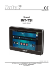
Table 1. Characters available in the keypad when entering telephone numbers (to change the
letter case, press
).
Special character
B
C
D
E
F
#
a
b
c
d
Function description
switch-over to pulse dialing
switch-over to tone dialing (DTMF)
waiting for additional signal
3 second pause
10 second pause
signal in DTMF mode
signal # in DTMF mode
other signals generated in DTMF mode
Table 2. Special character functions.
Entering names
Keep pressing particular keys until the required character appears. Characters available
in the keypad are presented in Table 3. Hold down the key to display the digit assigned
to the key.
Shown on the right side in the upper line of the display is information about the letter
case: [ABC] or [abc] (it will be displayed after pressing any key and will be visible for a
few seconds after the last keystroke).
The
key moves the cursor to the right, and the
key – to the left. The
key deletes the character on the left side of the cursor.
14
Programming Manual
Key
!
?
'
`
a
d
g
j
m
b
e
h
k
n
c
f
i
l
o
2
3
4
5
6
p
q
r
s
t
u
v
w
x
y
SATEL
Characters available after next keystroke
"
{
}
$ % & @ \
^
|
#
1
7
8
z
9
.
,
:
;
+
/
= _ < >
(
)
[
]
0
Table 3. Characters available in the LCD keypad when entering names. The lower case
letters are available under the same keys (to change the letter case, press
).
2.1.8
Entering data by means of the LED keypad
The data being entered are presented by means of LEDs. The method of programming
depends on the type of data to be entered by service function. To save the data in the control
panel, press the
key. To exit the function without saving the changes, press the
key.
Selection from the single-choice list
The lit LEDs show the available items on the list. Blinking LED indicates the current
position of the cursor and, consequently, the item which is currently selected. The
key moves the cursor to the right, and the
key – to the left. As all the LEDs are
numbered, you can use the numerical keys to select the item at once and move the
cursor there. The
and
keys are not used.
Selection from the multiple-choice list
The lit LEDs show which items have been selected. Blinking LED indicates the current
position of the cursor. The
key moves the cursor to the right, and the
key –
to the left. Press any numerical key to toggle the status of the LED over which the
cursor is placed (depending on its current status, the LED comes on or goes out). The
and
keys are not used.
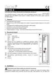
Entering decimal values
After entering the selected parameter programming function, the currently programmed
value will be presented in binary mode on LEDs 1-12 (see: Fig. 1). LEDs 1-4 present
(see: page 15 Table 4) the first digit , LEDs 5-8 – the second one, LEDs 9-12 – the third
one. To enter the new numerical value, press the corresponding numerical keys. You
can enter:
– 1 digit – it will be shown on LEDs 1-4 (the other LEDs are off);
– 2 digits – they will be shown on LEDs 1-8 (the other LEDs are off);
– 3 digits – they will be shown on LEDs 1-12.
The arrow keys are not used.
Correction of the entered value is only possible after re-entering the selected parameter
programming function.
SATEL
VERSA
15
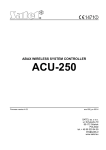
Fig. 1. Examples of presenting decimal values by means of LEDs in the LED keypad. Value
30 (030) is programmed in Example A, and value 160 in Example B.
LED status
Digits and characters
0
1
2
3
4
5
6
7
8
9
– LED OFF
– LED ON
A
B
C
D
E
F
Table 4. The binary mode of presenting digits and characters.
16
Programming Manual
SATEL
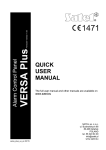
Entering hexadecimal values
After entering the selected parameter programming function, the currently programmed
value will be presented on the LEDs. Up to 6 characters can be presented (most
functions require a lesser number: 2 or 4 characters). LEDs 1-4 present in binary format
(see: page 15 Table 4) the first character, LEDs 5-8 – the second one, LEDs 9-12 – the
third one, LEDs 16-19 – the fourth one, 20-23 – the fifth one, and LEDs 24-27 – the
sixth one.
The digits are to be entered by pressing the corresponding keys. Characters from A to F
are available under the
and
keys. Keep pressing the keys until the required
character is displayed in binary mode on the LEDs (see: page 15 Table 4).
The arrow keys are not used.
Correction of the entered value is only possible after re-entering the selected parameter
programming function.
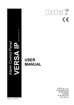
Fig. 2. Examples of presenting hexadecimal values by means of LEDs in the LED keypad.
Two-character value D5 is programmed in Example A, and four-character value E92B in
Example B.
Programming telephone numbers
The telephone numbers are entered in much the same way as in the LCD keypad,
however the LEDs can only present the first 6 characters (only digits and characters B,
C, D, E and F – see: page 15 Table 4).
The arrow keys are not used.
Correction of the entered value is only possible after re-entering the selected parameter
programming function.
SATEL
2.1.9
VERSA
17
Exiting the service mode
In order to exit the service mode, use the SERV.MODE END function.
To exit the service mode, do the following:
– in the LCD keypad, keep pressing the
key until the 0. SRVMOD CONFIG submenu
will appear in the upper line of the display, and then press successively the
keys;
– in the LED keypad, press the
key and then press successively the
keys.
2.2
DLOADX program
The DLOADX program enables data exchange between the computer and the control panel,
facilitates alarm system configuration, and ensures easy viewing of the status of zones,
partitions, outputs, troubles, and other components of the system. Access to the program is
protected by a code (password). To obtain access at the first run of the program, enter the
factory default code: 1234 (you need not enter the factory code, just click on the "OK"
button). It is recommended that the factory access code be changed.
Note: Entering an invalid code three times will terminate the program.
Communication between the program and the control panel is coded. The alarm control
panel may be programmed locally or remotely:
1. Local programming requires connection between the RS-232 (TTL) port on control
panel mainboard (RJ type socket) and the computer COM port. The connection should be
made by using the cable manufactured by SATEL and available in the DB9FC/RJ-KPL
set.
2. In case of remote programming, communication with the control panel can be effected:
– through the built-in 300 bps modem. This programming method requires connection
of the control panel to the telephone line. An analog modem must be connected on the
computer side.
– through the ETHM-1 module connected to the control panel. The ETHM-1 module
(with firmware version 1.04 or newer) and a computer with DLOADX program installed
must be connected to the Ethernet network (TCP/IP protocol).
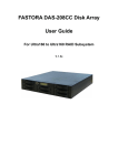
2.2.1
Main menu of the DLOADX program
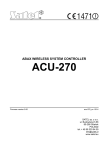
Fig. 3. Main menu of DLOADX program.
Explanations for Fig. 3:
1 - type of alarm control panel.
2 - name of alarm system / data file.
3 - information on data writing/reading progress.
18
Programming Manual
SATEL
4
- icon indicating the status of communication with the control panel:
– green color – ready to send data;
– alternating green and yellow color – data transmission in progress;
– gray color – COM port disabled.
A click on the icon button:
– in case of communication via the RS-232 port – will enable/disable the COM port;
– in case of other forms of communication – will display a window referring to the
given connection.
5 - information on the way of communication with the alarm control panel:
– COMn (n = number of COM port) – communication via the RS-232 port;
– Modem – communication via the modem.
– TCP/IP – communication through the ETHM-1 module.
Buttons:
System and hardware structure – button opens the "Versa – Structure" window.
Options and global times – button opens the "Global parameters" window.
Zones data – button opens the "Versa – Zones" window.
Outputs data – button opens the "Versa – Outputs" window.
Timers – button opens the "Versa – Timers" window.
Reporting – button opens the "Versa – Reporting" window.
Telephone messaging – button opens the "Versa – Tel. messaging" window.
Warning – the button is displayed if noncompliance with the EN 50131 standard
requirements for Grade 2 is found (with the GRADE 2 global option enabled). It
opens a window with information on the inconsistencies.
Panel’s data reading – button enables data reading from the control panel.
Write to panel – button enables data writing to the control panel.
Event log – button opens the window containing event log.
Cancel – button makes it possible to cancel the data reading/writing.
Clock setting – button saves the time in the control panel, based on the computer
clock.
LCD keypad – button displays a virtual keypad.
System status – button opens the drop-down menu shown in Fig. 4.
SATEL
VERSA
19
Configuration – button opens the "Configuration" window.
Connection – button opens the drop-down menu, where you can select the method
of establishing communication between the program and the alarm control panel.
Fig. 4. Menu displayed after pressing the
2.2.2
button.
Changing the program access code
1. Open the FILE menu, select ACCESS SETUP and then CHANGE ACCESS CODE (see: Fig. 5).
Fig. 5. Functions related to the access to DLOADX program.
2. Enter your present access code to the program and click on the "OK" button.
3. Enter the new access code to the program and click on the "OK" button.
4. Re-enter the new program access code and click on the "OK" button.
The program allows you to obtain access, based on additional access codes, which can be
defined and for which the authority level can be defined (FILE ACCESS SETUP PROGRAM
USERS – see: Fig. 5).
2.2.3
Parameters related to programming by means of the DLOADX program
In case of remote programming, it is necessary to configure some communication
parameters and options in the control panel. In case of local programming without verification
of identifiers, the parameters described below may be configured after communication with
the control panel is established.
20
Programming Manual
SATEL
Identifiers
The identifiers can be programmed:
– in the DLOADX program, "Identifiers and tel. no" window. The command for opening
this window is available in the COMMUNICATION menu. You can also open it by using
the Ctrl+R key combination.
– in the keypad, 0. SRVMOD CONFIG submenu.
VERSA identifier – identifier of the alarm control panel which makes it possible to
identify the control panel and match the data file to it, provided that the data file has
been saved on the computer. It consists of 8 hexadecimal characters (digits or letters
from A to F). The same identifier must not be programmed for different control panels
operated from the same computer (the DLOADX program will be incapable of
distinguishing between them).
DLOADX identifier – identifier of the computer with DLOADX program. If communication
is effected, including verification of identifiers, the control panel will only establish
connection with the program which uses the valid identifier. It consists of 8
hexadecimal characters (digits or letters from A to F).
Note: In case of establishing communication with the alarm system whose identifiers
have factory defaults (00000000), the DLOADX program will suggest random
generated identifiers.
Telephone communication parameters
The telephone numbers are programmed in:
– DLOADX program, "Identifiers and tel. no" window;
– keypad, 0. SRVMOD CONFIG submenu (only computer telephone number).
The number of rings is programmed in:
– DLOADX program, "Global parameters" window;
– keypad, 7. ANSWERING submenu.
Options related to remote programming via the modem (e.g. ANSWERING – MODEM and
DOUBLE CALL) are described in Section GLOBAL OPTIONS.
VERSA panel telephone number – telephone number of the control panel. Available
for programming only in DLOADX program.
PC telephone number – telephone number of the computer from which the control
panel is to be programmed. It should be programmed if the telephone connection is
to be made by the control panel (the panel initiates the connection or calls back).
Rings before answer – number of rings after which the control panel will go off hook.
Parameters of communication via Ethernet (TCP/IP) network
The IP address of computer with DLOADX program (SERVER), TCP port for
communication through Ethernet network, encryption key (DLOADX KEY) and the
DLOADX->ETHM-1 CONNECTION option are programmed for the ETHM-1 module (see:
section ETHM-1 ETHERNET MODULE – p. 47):
– in the "Versa – Structure" window, "Hardware" tab, after the ETHM-1 module has
been selected in the list;
– in the keypad, by means of the SETTINGS function (SERVICE MODE 2. HARDWARE
1. KPDS. & EXPS. 2. SETTINGS), after the ETHM-1 module has been selected from
the list that will be displayed (the programming is effected by the "step by step"
method).
SATEL
VERSA
21
In the DLOADX program, the TCP port for communication via Ethernet network and the
encryption key should be additionally defined in the "Identifiers and tel. no" window. The
ETHM-1 module address should be programmed in the same window.
2.2.4
Starting local programming without verification of identifiers
With this method of establishing communication between computer and alarm control panel
you do not have to know any identifiers programmed in the control panel (the START DWNLRS
function will be activated automatically). After establishing communication with the control
panel, identifiers will be read by the DLOADX program.
1. Connect the control panel RS-232 (TTL) port with the computer port.
2. Enter the service code (by default: 12345) and press the
key.
3. Press in turn the
keys to start the service mode.
4. Start the DLOADX program on the computer. If the control panel RS-232 (TTL) port is
connected to the computer COM1 port, communication with the control panel will start
automatically. Otherwise, click on the
button and, in the window that will open,
indicate the computer port through which communication is to be effected.
5. The DLOADX program will signal establishing communication by displaying an appropriate
message.
2.2.5
Starting local programming with verification of identifiers
Communication between the computer and the alarm control panel in this mode will be
established, when the communication identifiers in control panel and program are identical or
the identifiers programmed in the control panel have the factory value.
1. Connect the control panel RS-232 (TTL) port with the computer port.
2. Enter the service code (by default: 12345) and press the
key.
3. Press in turn the
keys (the START DWNLRS function will start).
4. Start the DLOADX program on the computer. If the control panel RS-232 (TTL) port is
connected to the computer COM1 port, communication with the control panel will start
automatically. Otherwise, click on the
button and, in the window that will open,
indicate the computer port through which communication is to be effected.
5. The DLOADX program will signal establishing communication by displaying an appropriate
message.
2.2.6
Starting local programming "from pins"
If the local programming cannot be started in normal manner, you can use the emergency
hardware procedure, so-called starting "from pins".
1. Connect the control panel RS-232 (TTL) port with the computer port.
2. Start the service mode in the control panel "from pins" (see: Section STARTING THE
SERVICE MODE "FROM PINS").
3. Start the DLOADX program on the computer. If the control panel RS-232 (TTL) port is
connected to the computer COM1 port, communication with the control panel will start
automatically. Otherwise, click on the
button and, in the window that will open,
indicate the computer port through which communication is to be effected.
4. The DLOADX program will signal establishing communication by displaying an appropriate
message.
22
Programming Manual
2.2.7
SATEL
Finishing local programming
The local programming function will stop automatically after 4 hours have elapsed since
operation of the DLOADX program was completed. The function may also be terminated by
using the FINISH DWNLRS command, available from the keypad.
1. Enter in the keypad the service code (by default 12345) and press the
key.
2. Press in turn the
keys (to start the FINISH DWNLRS function).
2.2.8
Starting remote programming via modem
For remote programming to be possible, the modem and the control panel must be suitably
configured. Communication between the control panel and the modem can be established in
a few ways:
1. Connection is initiated from the DLOADX program.
2. Connection is initiated from the DLOADX program, but the control panel calls back and
establishes the connection.
3. Connection is initiated by the control panel.
Note: The communication identifiers in control panel and program must be identical, or the
control panel identifiers must have their factory default value.
Configuring settings of modem connected to computer
Configuration of the modem connected to computer is possible by using the DLOADX
program. For this purpose, click on the
button. The "Configuration" window will
open, in which you should click on the "Modem" tab. When you click on the
button, you will be able to edit parameters of the port used for communication with
the modem, as well as the initiation commands.
Initiating connection from the DLOADX program
Connection with the control panel can be established from any location. Make sure that
in the control panel:
• the computer telephone number has not been programmed!
• the ANSWERING – MODEM option is enabled (SERVICE MODE 3. GLOBAL PARAM.
1. OPTIONS MODEM ANSWERING);
• you have defined the number of rings after which the control panel will go off-hook
(SERVICE MODE 7. ANSWERING 1. RINGS TO ANS.);
• you have defined whether the control panel will go off-hook after the first, or after the
second call (SERVICE MODE 3. GLOBAL PARAM. 1. OPTIONS DOUBLE CALL).
Telephone number of the control panel must be programmed in the DLOADX program.
1. Start the DLOADX program on computer.
2. Initialize the modem connected to the computer. For the modem to be initialized,
click on the
button and, from the menu that will be displayed, select the 300
bps modem. The window will then open where the modem initializing information will
be shown.
3. Click on the "Connect" button.
4. After the preprogrammed number of rings (after the second call, if the DOUBLE CALL
option is enabled), the control panel will answer the call and the connection will be
established. The DLOADX program will signal it by an appropriate message.
SATEL
VERSA
23
Initiating connection from the DLOADX program, but with the control panel
calling back and establishing connection
This method ensures better security of the system, because the control panel may
only be remotely programmed from a specified locality. Make sure that in the control
panel:
• you have programmed telephone number of the computer from which the control
panel is to be programmed (SERVICE MODE 0. SRVMOD CONFIG 4. DLOADX TEL.);
• the ANSWERING – MODEM option is enabled (SERVICE MODE 3. GLOBAL PARAM.
1. OPTIONS MODEM ANSWERING);
• you have defined the number of rings after which the control panel will go off-hook
(SERVICE MODE 7. ANSWERING 1. RINGS TO ANS.);
• you have defined whether the control panel will go off-hook after the first, or after the
second call (SERVICE MODE 3. GLOBAL PARAM. 1. OPTIONS DOUBLE CALL).
Telephone number of the control panel must be programmed in the DLOADX program.
1. Start the DLOADX program on computer.
2. Initialize the modem connected to the computer. For the modem to be initialized,
click on the
button and, from the menu that will be displayed, select the 300
bps modem. The window will then open where the modem initializing information will
be shown.
3. Click on the "Connect" button.
4. After the preprogrammed number of rings (after the second call, if the DOUBLE CALL
option is enabled), the control panel will answer the call, acknowledge receiving the
connection, and then disconnect.
5. The control panel will call back the number programmed in the control panel and the
connection will be established, which will be indicated by the DLOADX program by an
appropriate message.
Initiating connection by the control panel
Like the previous method, also this one ensures enhanced security of the system,
because the control panel may only be remotely programmed from a specified locality. It
can be applied if the system user prefers that the remote programming cannot be
carried out without his knowledge. Telephone number of the computer from the control
panel is to be programmed must be programmed in the control panel (SERVICE MODE
0. SRVMOD CONFIG 4. DLOADX TEL.).
1. Start the DLOADX program on computer.
2. Initialize the modem connected to the computer. For the modem to be initialized,
click on the
button and, from the menu that will be displayed, select the 300
bps modem. The window will then open where the modem initializing information will
be shown.
3. Enter in the keypad the service code (by default 12345) or the code of user having
the DOWNLOAD/SERVICE privilege and press the
key.
4. Press in turn the
keys (the START DWNLTEL con. function will
start).
5. The DLOADX program will signal establishing communication by an appropriate
message.
24
Programming Manual
2.2.9
SATEL
Starting remote programming via Ethernet network
Communication between the DLOADX program and the control panel through the ETHM-1
module can be established in two ways:
1. Initiating connection from the DLOADX program.
2. Initiating connection by the control panel.
Note: The communication identifiers in control panel and program must be identical, or the
control panel identifiers must have their factory default value.
Initiating connection from the DLOADX program
This method enables establishing a connection with the control panel from any location.
Do the following in the control panel (SERVICE MODE 2. HARDWARE 1. KPDS. & EXPS.
2. SETTINGS module name
["step by step" programming method]):
• enable the DLOADXETHM-1 option [the option is available in step 2];
• define the TCP port which will be used for communication (DLOADX PORT [step 9]);
• enter the data encryption key (DLOADX KEY [step 10]).
The following must be programmed in the DLOADX program ("Identifiers and tel. no"
window):
• ETHM-1 module address (SERVER);
• TCP port that will be used for communication (PORT);
• data encryption key (DLOADX KEY).
1. Start the DLOADX program in the computer.
2. Click on the
button and, in the menu that will be displayed, select the "TCP/IP:
DloadX -> ETHM" command. The "TCP/IP: DloadX -> ETHM connection" window
will open.
3. Click on the "Connect" button in the "TCP/IP: DloadX -> ETHM connection" window.
4. Establishing communication with the ETHM-1 module and the control panel will be
confirmed by suitable messages.
Initiating a connection by the control panel
This method ensures better security of the system, because the control panel may only
be remotely programmed from a specified location. It is applicable when the system
user does not want the remote programming to be carried out without his knowledge.
The following must be programmed in the control panel (SERVICE MODE 2. HARDWARE
1. KPDS. & EXPS. 2. SETTINGS module name
["step by step" programming]):
• address of the computer with DLOADX program (DLOADX [step 8]);
• TCP port that will be used for communication (DLOADX PORT [step 9]);
• data encryption key (DLOADX KEY [step 10]).
The following must be programmed in the DLOADX program ("Identifiers and tel. no"
window ):
• TCP port that will be used for communication (PORT);
• data encryption key (DLOADX KEY).
1. Start the DLOADX program in the computer.
SATEL
VERSA
25
2. Click on the
button and, in the menu that will be displayed, select the "TCP/IP:
DloadX <- ETHM" command. A window will open in which information server
activation will be displayed.
3. Enter in the keypad the service code (by default 12345) or the code of user having
the DOWNLOAD/SERVICE right and press the
key.
4. Press in turn the
keys (starting the ETHM-1DLOADX function).
5. The DLOADX program will signal establishing communication with a suitable
message.
3. Global Parameters
User code min. lenght – the minimum number of characters required for the control panel to
accept a new code or a changed code.
3.1
Global options
Reporting – TELEPHONE – the control panel can send event codes to the monitoring
station by means of the telephone line.
Reporting – ETHM – the control panel can send event codes to the monitoring station via
the Ethernet network, using the TCP/IP protocols.
Telephone messaging – the control panel can notify about the occurrence of specific events
by means of voice or text messages using the telephone links.
Answering – modem – external initiation of the modem communication with the control
panel is possible.
Double call – the control panel must be called twice for the modem communication to be
established. The first time you must wait for the preprogrammed number of rings and hang
up. Then you must call back within three minutes and the control panel will answer the call
immediately. This solution makes it possible to connect after the control panel some
additional devices which will be activated after a preset number of rings (e.g. answering
machine, fax, etc. ).
Tone dialing – the control panel will tone dial the telephone numbers (pulse dial, if this
option is disabled).
Pulse 1/1.5 (off 1/2) – this option applies to pulse dialing. Before you enable it, make
yourself familiar with the valid standard of pulse dialing.
No dial tone test – the control panel will not perform the test for dial tone before dialing the
number and will start dialing the number 5 seconds after going "off hook". This makes it
possible for the control panel to dial the number when some non-standard tones occur on
the telephone line after going off hook (e.g. interrupted tone). When this option is disabled,
the control panel will start dialing the number 3 seconds after going off hook, provided that
the dial tone is present.
No answer tone test – in case of notifying by means of voice messages, the control
panel will not perform the test for "off hook" condition. The voice message will be
played back 15 seconds after completion of the number dialing. In case of reporting,
the control panel will ignore any signals (including the busy tone) received from the
telephone exchange after dialing the telephone number, and will wait for the
handshake from the monitoring station. Enable this option if, after dialing the number,
non-standard signals are received from the telephone exchange or in case of very
poor quality connections.
Store keyfob events – using the keyfob is written into the events log.
26
Programming Manual
SATEL
Trouble memory until review – the trouble memory is being signaled until it is cleared
(clearing the trouble memory is possible when you quit the 7. SYSTEM STATE user function).
Grade 2 – the system operates in accordance with the EN 50131 standard requirements for
Grade 2, i.e.:
– the way of informing the users about the system state by means of LEDs, display and
beeps in the keypads meets the requirements of the standard (see: USER MANUAL);
– quick arming is not available;
– new codes in the system must be composed of at least 5 characters;
– prior to arming, the control panel checks that no circumstances have occurred that
prevent arming (ref. PREVENT ARMING IF NOT READY global option),
– in case of arming by means of the LCD keypad, the control panel will check if there are
any zones bypassed in the partition – information on the bypassed zones is presented,
if the user has the INSPECTION right,
– the warning alarm feature is enabled in the system (see: WARNING ALARM global option),
– the warning alarm is signaled at the 2. INTERNAL SIREN function output (ref. WARNING
ALARM ON INTERNAL SIRENS global option).
The option is available in the keypad in the 2. HARDWARE submenu (SERVICE MODE
2. HARDWARE 1. KPDS & EXPS. 4. OPTIONS GRADE2).
Serial data on OUT 3/4 – OUT3 and OUT4 outputs send the system status data (zone
alarms, fire alarms, troubles, armed modes, etc.) and do not execute any other
programmed functions. The outputs may be used to control the NR2-DSC radio monitoring
transmitter (NEMROD system – PC-16 OUT format), made by NOKTON.
OUT 3/4 data extended mode – this option is active, if the SERIAL DATA ON OUT 3/4 option is
enabled. The OUT3 and OUT4 outputs will send the system status data in the form of
frames (PC-16 OUT UA format).
Arming/Disarming/Clearing signaling from zones only – outputs with the functions
1. EXTERNAL SIREN and 2. INTERNAL SIREN with enabled ARMING/DISARMING/CLEARING
SIGNALING option will signal only:
– starting of the arming procedure by zone or by means of keyfob;
– no possibility of arming (see: PREVENT ARMING IF NOT READY option or GRADE 2 option), if
the arming command has been sent from keyfob;
– failed attempt of arming by means of keypad or keyfob (see: PREVENT ARMING IF NOT
READY option or GRADE 2 option);
– disarming by zone or by means of keyfob;
– alarm clearing by zone or by means of keyfob.
Starting the arming procedure, disarming or alarm clearing by means of keypad, proximity
card arm/disarm device or timer are not signaled.
Clear messaging on alarm clearing – clearing the alarm will automatically cancel
messaging about this alarm, if the user clearing the alarm has the TELEPHONE MESSAGING
CLEARING right.
Service message after tamper alarm – this option is active, if the TROUBLE MEMORY UNTIL
REVIEW option is enabled. Information on the tamper alarm can only be cleared from the
troubles memory by using the service code. In the LCD keypad, the " System tamper, call
service" message will be displayed after the tamper alarm (unless the alarm messages are
displayed). The message will no longer be displayed after the troubles memory is reset by
the service.
Warning alarm – the system includes an activated warning alarm feature, whose purpose is
to delay the loud signaling and reporting, if any mistakes are made when entering the
protected facility. The warning alarm is not monitored. It can be signaled on the keypad,
SATEL
VERSA
27
proximity card arm/disarm device or outputs with the function 2. INTERNAL SIREN. The
warning alarm is triggered by the following zone types:
– 0. ENTRY/EXIT or 1. ENTRY/EXIT FINAL – unless the system is disarmed before completion
of the ENTRY DELAY countdown;
– 2. ENTRY/EXIT ROUTE – if it is violated during the ENTRY DELAY countdown, and the
system is not disarmed before completion of the DELAY TIME countdown;
– 3. INSTANT – if it is violated during the ENTRY DELAY countdown.
The warning alarm lasts 30 seconds. Unless the alarm system is disarmed during this
time, the alarm will be triggered by the zone.
Warning alarm on internal sirens – this option is active, if the WARNING ALARM option is
enabled. The warning alarm will be signaled on outputs with the 2. INTERNAL SIREN
function.
Tamper alarm always audible – the tamper alarm will be signaled always on outputs with
the 1. EXTERNAL SIREN and 2. INTERNAL SIREN functions (if the option is disabled, only in
armed mode). Also, lack of the expander is always saved in the event log as a tamper
alarm. If the option is disabled, lack of the expander will be saved in the event log:
– as a trouble, if the partition to which the expander is assigned, is disarmed (but the
keypad will signal tamper alarm anyway);
– as a tamper alarm, if the partition is armed.
Tamper alarm on internal sirens – the tamper alarm will be signaled always on outputs with
the 2. INTERNAL SIREN function (in armed mode only if the option is disabled). Additionally,
the output will always signal lack of the expander (also when the event is logged as
a trouble – see: TAMPER ALARM ALWAYS AUDIBLE option).
Block after 3 unknown codes/cards – after entering an invalid code / reading in an invalid
card three times, the keypad / proximity card arm/disarm device will be blocked for 90
seconds. After this period of time has expired, each subsequent entry of an invalid code /
read-in of an invalid card will block the keypad / proximity card arm/disarm device at once.
The counter of invalid codes / cards will be reset after a correct code is used.
Service Mode from RESET pins – it is possible to start the service mode and local
programming "from pins" (on the keypad this option is available in the 0. SRVMOD CONFIG
submenu (SERVICE MODE 0. SRVMOD CONFIG 6. SRVMOD OPT. SRVMOD VIA
RESET)).
Limit storing "Test transmission" events – if the "Test transmission" events directly follow
one another, they are only written to the event log 3 times. Information on sending next
test transmissions is not recorded. Any other event occurring in the system will reset the
counter of "Test transmission" events, i.e. it will be possible to log next three consecutive
test transmissions.
Prevent arming if not ready – if the user arm the system by means of keypad or keyfob, the
control panel checks that there are no circumstances that prevent the arming:
– a zone with PRIORITY option is violated in the partition which is to be armed;
– the 3. INSTANT, 4. DOUBLE KNOCK, 5. 24H BURGLARY, 6. 24H TAMPER, 7. 24H PANIC, 8. 24H
PANIC SILENT, 9. 24H MEDICAL or 10. 24H FIRE type zone is violated in the partition which
is to be armed;
– there is a trouble in the system.
If one of the aforementioned situations takes place, the control panel will not start the
arming procedure (the LCD keypad enables forced arming – see: USER MANUAL). If none of
the conditions is met, the control panel will start the arming procedure, but at the end of
the exit delay countdown it will check again if the arming is possible (the quick arming
being an exception). A violated zone or a trouble mean that the arming is not possible (i.e.
the arming procedure will fail).
28
Programming Manual
SATEL
Additionally, when the option is enabled and the user has the INSPECTION right, the LCD
keypad will inform, prior to arming, that there are bypassed zones in the partition (it does
not apply to the quick arming).
The option is available in the keypad in the 2. HARDWARE submenu (SERVICE MODE
2. HARDWARE 1. KPDS & EXPS. 4. OPTIONS ADVANCED ARMING).
Arm even if not ready after exit delay – the option is active, when the PREVENT ARMING IF
NOT READY or GRADE 2 option is enabled. A zone violation or trouble found at the end of
exit delay countdown does not affect the arming procedure – the system will be armed.
The option is available in the keypad in the 2. HARDWARE submenu (SERVICE MODE
2. HARDWARE 1. KPDS & EXPS. 4. OPTIONS ARM EXDLY W.TRBL).
Answering/remote control when armed partition 1 / 2 – telephone answering and remote
control features are only available when selected partitions are armed.
Note: Additionally, the list of global options in the keypad includes:
– TMP ALARM IN P.2 – alarm from the mainboard TMP zones is signaled in partition 2.
In the DLOADX program, the partition in which alarm from TMP zones will be
signaled is to be selected in the "Versa – Structure" window, "Hardware" tab, after
clicking on the system name on the left side;
– EVENTS LIMITAT., EXP. RESTART. REP., REST. AFT. BELL and REST. AFT. DISARM. –
options available in the DLOADX program, "Versa – Reporting" window, and
described in section REPORTING PARAMETERS AND OPTIONS.
3.2
Global times
Keypad’s alarm time – time period during which alarm is signaled in keypads and proximity
card arm/disarm devices. Up to 255 seconds can be programmed. Programming the value
0 means that the KEYPAD’S ALARM TIME will be 3 seconds.
No armed indication after – time counted from the moment of partition arming, after expiry
of which the keypad LED indicating the partition armed status will go out. Up to 255
seconds can be programmed. Programming the value 0 means that the LED will be lit as
long as the partition is armed.
AC loss report delay – time during which the control panel must be without AC power
before the trouble is reported. A delay in reporting the trouble prevents sending information
about short-time voltage decays, having no effect on normal operation of the system. The
trouble reporting delay can be up to 255 minutes.
Telephone line loss report delay – time during which abnormal voltage must be on the
telephone line for the control panel to report the telephone line trouble. A delay in reporting
the trouble prevents sending information about short-time voltage dips (e.g. during a
phone call) or decays. The trouble reporting delay can be up to 255 minutes.
RTC clock correction – if the accuracy of control panel clock is inadequate, the clock
settings may be adjusted once per 24 hours (at midnight) by a defined time. The correction
time is programmed in seconds. The maximum correction can be ±19 seconds per 24
hours.
Summer/winter time – the control panel can automatically adjust the clock settings due to
a change from the summer time to the winter time and vice versa. The following correction
schemes are available:
– no correction;
– according to the European Union rules;
– according to the United States' rules;
– correction by 1 hour according to dates;
– correction by 2 hours according to dates.
SATEL
VERSA
29
Summer time from / Winter time from – if the control panel clock is to be corrected by 1 or
2 hours according to dates, you should enter the dates (day, month) after the clock is
changed to the summer time (moved forward) or to the winter time (moved back).
4. Partitions
A system based on the VERSA control panels can be subdivided into 2 partitions. The
partition means a separated area in the premises protected by the alarm system. Because
the partitions can be armed independently, subdividing the system into partitions will allow
the user to arm/disarm just a part of the premises. Additionally, the subdivision into partitions
makes it possible to restrict access to a part of the premises to selected users.
In the DLOADX program, the partition parameters are programmed in the "Versa – Structure"
window, "System" tab. The partitions and zones are presented in a tree-like form on the left
side of the window (see: Fig. 6). In the keypad, the partition parameters are configured by
using the functions available in the PARTITIONS submenu (SERVICE MODE 1. PARTITIONS).
Fig. 6. List of partitions and zones in a tree-like form in the "System" tab, "Versa – Structure"
window (an example of configuration).
4.1
Partition parameters
Name – individual name of the partition (up to 16 characters ).
Partition exit delay – the time counted from the moment of starting the partition arming
procedure which enables the protected area to be left without triggering an alarm.
Violation of the 0. ENTRY/EXIT, 1. ENTRY/EXIT FINAL, 2. ENTRY/EXIT ROUTE or 4. DOUBLE
KNOCK type zones during the exit delay time will trigger no alarm. Up to 255 seconds
can be programmed.
Notes:
• The exit delay countdown can be terminated by means of the 1. ENTRY/EXIT FINAL or
16. EXIT DELAY TERMINATOR type zones. All zones in the partition will be armed before
expiry of the programmed exit delay time.
• Using the keypad, you can arm the system without the exit delay, if the hold down the
key which ends the arming sequence (
,
or
) for approx. 3 seconds.
30
Programming Manual
SATEL
Infinite exit delay – the partition exit delay can only be ended by means of the 1. ENTRY/EXIT
FINAL, 16. EXIT DELAY TERMINATOR or 17. SHUNT LOCK type zones. If the exit delay
countdown is not completed, the armed mode will not be activated (only the 3. INSTANT
type zones will be armed).
Entry delay – the time counted from the moment of entry into the protected area which
enables the partition to be disarmed before triggering an alarm. This parameter
applies to the 0. ENTRY/EXIT and 1. ENTRY/EXIT FINAL type zones. The delay
programmed for the partition is taken into account in case of the zones for which the
value 0 has been individually programmed. The delay is programmed in seconds. Up
to 255 seconds can be programmed. If the value 0 is programmed, the zone will act
as an instant one.
Warning time – the time of warning alarm signaling for the partial armed mode (see:
WARNING IN PARTIAL ARMING zone option). The time is programmed in seconds. Up to 255
seconds can be programmed. If the value 0 is programmed, the WARNING TIME will be 30
seconds. After expiry of the WARNING TIME, unless the partition is disarmed, the burglary
alarm will be triggered.
Fig. 7. Programming partition parameters in the "Versa – Structure" window, DLOADX
program (an example of configuration).
Note: The WARNING TIME parameter does not apply to the time of signaling the warning alarm
which is generated when mistakes are made when entering into the protected object
(see: WARNING ALARM global option).
Verification time – programming a value different from 0 means activating the alarm
verification feature in the partition. Subject to verification are alarms from 0 to 5 type
zones. The VERIFICATION TIME runs from the moment of alarm being triggered by such a
zone. If during the VERIFICATION TIME an alarm is triggered by another zone in the partition,
programmed as 0 to 5 type, the control panel will report a verified alarm. The time is
programmed in minutes. Up to 255 minutes can be programmed.
Timer priority – the timer will always disarm the partition according to the preset times (if this
option is disabled, the timer will only disarm the partition, if the arming was done by the
timer).
Auto-arming delay – the time counted from the moment when the timer is to arm the
partition, enabling the arming to be deferred. The delay time is programmed in seconds.
Up to 255 seconds can be programmed. Programming the value 0 means that the arming
deferment will be unavailable.
SATEL
VERSA
31
Deferment time – the time by which the user can defer arming by the timer. The time is
programmed in minutes. Up to 255 minutes can be programmed. Programming the value 0
means that the arming deferment will be unavailable.
Simple deferment – the user can defer auto-arming by pressing the
key twice during
the auto-arm delay time countdown.
Single deferment – the user can only use the simple deferment once, so as to postpone the
auto-arming. Subsequent arming deferments are only possible by using the AUTO-ARMING
6. SETTINGS 1. A-ARM DEFER.).
DEFERMENT user function ([CODE]
5. Zones
Fig. 8. "Versa – Zones" window in the DLOADX program.
A zone can be assigned to one or two partitions. If the zone is assigned to two partitions, it
can be armed when both partitions are armed or one of them only.
The system supports the following zones:
• hardwired – on the control panel PCB and in expanders. The number of available
hardwired zones is determined by the control panel during the identification procedure.
• wireless – after connecting the 433 MHz wireless system controller (VERSA-MCU) or the
ABAX wireless system controller (ACU-100 or ACU-250). The number of available
wireless zones depends on the number of wireless devices registered in the system and is
determined during the procedure of adding them.
• virtual – zones which do not physically exist, but are controlled by means of keyfobs.
In the DLOADX program, parameters and options of the zones can be programmed in the
"Versa – Structure" window, "System" tab. Partition and zones are presented in the tree-like
form on the left-hand side of the window (see: Fig. 6). The zone parameters and options can
also be programmed in the "Versa – Zones" window (see: Fig. 8).
In the keypad, parameters and options of the zones are configured by means of the Zones
function (SERVICE MODE 2. HARDWARE 2. ZONES). The programming is performed using
the "step by step" method (the numbers are shown in binary form on the
and
LEDs of
the first and second partitions):
1. Zone selection.
2. EOL type.
3. Sensitivity [line type NO, NC, EOL and 2EOL].
4. Pulse validity [only for ROLLER type of line].
32
Programming Manual
SATEL
5.
6.
7.
8.
9.
Pulses count [only for ROLLER type of line].
Sensitivity [only for Vibration type of line].
Pulses count [only for Vibration type of line].
Zone type.
Alarm delay [ARM MODE should be programmed in this step for 13. ARM/DISARM and
14. ARMING type zones, and the EVENT parameter for the 19. TROUBLE type zone].
10. Max. violation time.
11. Max. no violation time.
12. Zone options.
13. Zone name [only in LCD keypad].
5.1
5.1.1
Numeration of system zones
Hardwired zones
Numbers are assigned to the hardwired zones automatically:
• the zones on control panel PCB always have initial numbers (1-5 for the VERSA 5 control
panel; 1-10 for the VERSA 10 control panel; 1-15 for the VERSA 15 control panel);
• the zones in expanders are numbered depending on the address which is set in them:
– expander with address 12 (0Ch) – numbers from 7 to 14;
– expander with address 13 (0Dh) – numbers from 15 to 22;
– expander with address 14 (0Eh) – numbers from 23 to 30.
If the expander zones coincide with those on the control panel PCB, you may define which of
the zones will be supported by the mainboard, and which ones by the expander. In the
keypad, the VERSA ZONES service function (SERVICE MODE 2. HARDWARE 7. VERSA
ZONES) is provided for this purpose. In the DLOADX program, this can be done in the "Versa –
Structure" window, "System" tab, when programming the selected zone.
5.1.2
Wireless zones
The wireless zones may be assigned any numbers in the system. The numbers are assigned
during the procedure of adding wireless devices. When the wireless zone number coincides
with that of the hardwired zone, you may define which of the zones is to be supported. In the
keypad, the WIRELSS.ZONES service function (SERVICE MODE 2. HARDWARE 1. KPDS &
EXPS. 3. WIRELESS MOD. 4. WIRELSS.ZONES). is provided for this purpose. In the DLOADX
program, this can be done in the "Versa – Structure" window, "System" tab, when
programming the selected zone.
5.2
End of line resistors
For the zones on mainboard and in zone expanders identified by the control panel as
CA-64 Ei and CA-64 EPSi, the value of resistors used in the EOL and 2EOL wiring types is
programmable within the range from 500 Ω to 15 kΩ.
In the DLOADX program, the resistor value should be entered in the "Versa – Structure"
window, "Hardware" tab, after indicating the mainboard or selected zone expander in the list.
In the keypad, the resistor value should be programmed as follows:
– for mainboard – by means of the EOL 1 RESISTOR and EOL 2 RESISTOR function
(SERVICE MODE 2. HARDWARE 5. EOL 1 RESIST. / 6. EOL 2 RESIST.).
– for zone expander – during configuration of the expander by using the SETTINGS
function (SERVICE MODE 2. HARDWARE 1. KPDS & EXP. 2. SETTINGS ).
SATEL
VERSA
33
Notes:
• The sum of values programmed for the resistors R1 and R2 may not be lower than 500 Ω
or higher than 15 kΩ.
• In case of the zone expander, it is possible to program the value 0 for the resistor R2. The
2EOL wiring type requires that two resistors be used, each having resistance equal to half
the value defined for the resistor R1.
• In the EOL wiring type, the resistance value is equal to the sum of values programmed for
the resistors R1 and R2.
5.3
Zone parameters
Fig. 9. Programming the zone parameters in "Versa – Structure" window in the DLOADX
program (an example of configuration).
Zone name – individual name of zone (up to 16 characters).
Partition 1 / Partition 2 – partition to which the zone is assigned. The zone must be
assigned at least one partition, for its status to be supervised.
Entry delay – the time counted from the moment of violating the 0. ENTRY/EXIT or 1. ENTRY/EXIT
FINAL type zone, which makes disarming possible before triggering the alarm. It is
programmed in seconds and can be up to 255 seconds. If the value 0 is programmed, the
ENTRY DELAY programmed for the partition will be taken into account. If the value 0 is
programmed for both the zone and the partition, the zone will act as an instant one.
Delay time – the time counted from the moment of violating the 2. ENTRY/EXIT ROUTE type
zone, if it acts as a delayed one. The time is programmed in seconds and can be up to 255
seconds. If the value 0 is programmed, the ENTRY DELAY programmed for the partition will
be treated as the DELAY TIME. If the value 0 is programmed for both the zone and the
partition, the zone will act as an instant one.
Delay activation time – the time counted from the moment of violating the 18. ENTRY ROUTE
ENABLING type zone. During countdown of this time, the 2. ENTRY/EXIT ROUTE type zone will
34
Programming Manual
SATEL
act as the delayed ones. The time is programmed in seconds and can be up to 255
seconds. If the value 0 is programmed, the ENTRY DELAY programmed for the partition will
be treated as the DELAY ACTIVATION TIME. If the value 0 is programmed for both the zone
and the partition, violation of the zone will have no effect.
Waiting time – the time counted from the moment of violating the 4. DOUBLE KNOCK type
zone. If the zone is violated again during the waiting time, it will trigger alarm. The time is
programmed in seconds and can be up to 255 seconds. Programming the value 0 means
that the WAITING TIME will be 30 seconds.
Note: In the LCD keypad, the ENTRY DELAY, DELAY
parameters are programmed as the ALARM DELAY.
ACTIVATION TIME
and WAITING
TIME
Arm mode – the armed mode activated after violating the 13. ARM/DISARM or 14. ARMING
type zone. You can select either fully arming, day arming or night arming.
Event – number of the event that will be written into the control panel memory and can be
reported to the monitoring station upon violation of the 19. TROUBLE type zone. You can
enter the following values for the corresponding codes of alarm events:
1 – 201 Low water pressure
2 – 202 Low CO2
3 – 203 Gate valve sensor
4 – 204 Low water level
5 – 205 Pump activated
6 – 206 Pump failure
51 – 151 Gas detected
52 – 152 Refrigeration
53 – 153 Loss of heat
54 – 154 Water leakage
55 – 155 Foil break trouble
56 – 156 Day trouble
57 – 157 Low bottle gas level
58 – 158 High temperature
59 – 159 Low temperature
61 – 161 Loss of air flow
62 – 162 Carbon monoxide (CO) detected
63 – 163 Tank level trouble
Entering a different value means that the zone violation will trigger the trouble signaling,
but no alarm events from zone will be written to the event log.
Wiring type – type of detector and the method of its connection (zone configuration):
no detector – no detector is connected to the zone;
NC – the zone supervise a detector of NC (normally closed) type;
NO – the zone supervise a detector of NO (normally open) type;
EOL – the zone supervise a NO or NC detector with single EOL resistor;
2EOL/NO – the zone supervise a NO detector with double EOL resistors;
2EOL/NC – the zone supervise a NC detector with double EOL resistors;
roller – the zone supervise a roller shutter detector;
vibration – the zone supervise a vibration detector.
Note: In case of the VIBRATION zone wiring, opening the circuit for 200 ms – irrespective of
the programmed number of pulses and sensitivity (see below) – will be interpreted as
violation. This solution enables a magnetic contact to be connected in series with the
vibration detector.
SATEL
VERSA
35
Sensitivity – depending on selected wiring type:
– NO, NC, EOL and 2EOL – the time during which the zone must be violated, so that it
can be noted by the control panel. The sensitivity is programmed in milliseconds.
Values from the 20 ms to 5100 ms range can be entered.
– Vibration – the pulse whose duration is equal to or longer than the defined time will
cause violation of the zone. Values from the 3 ms to 96 ms range can be programmed
(every 3 ms).
Pulse validity – the time counted from the pulse occurrence during which subsequent pulses
must occur (their number being defined as the PULSE COUNT) so that the zone is violated.
The following values can be programmed: 30 s, 120 s, 240 s and 0. If no further pulses will
occur within the defined time period, the pulse counter will be reset. The pulse counter is
reset automatically at arming/disarming. If the value 0 is programmed, the counter will only
be reset at arming/disarming. This parameter is programmed for the ROLLER zone wiring.
Pulse count – the number of pulses after which the zone will be violated. This parameter is
programmed for the ROLLER and VIBRATION zone wiring. For the VIBRATION zone wiring, it is
possible to program values from 0 to 7 (for the value 0, the pulses will not be counted, the
SENSITIVITY parameter only being taken into account). For the ROLLER zone wiring, you can
program values from 1 to 8.
Note: In the DLOADX program, all the required parameters for zones in ROLLER and
VIBRATION configuration are programmed in the “Sensitivity” field.
Max. violation time – exceeding the maximum violation time is recognized by the control
panel as the detector trouble (e.g. damage or masking). The time is programmed in
seconds and can be up to 255 seconds. Programming the value 0 means that the control
panel will not check the zone for maximum violation time.
Max. no violation time – exceeding the maximum time of no violation is recognized by the
control panel as the detector trouble (e.g. damage or masking). The time is programmed in
hours and can be up to 255 hours. Programming the value 0 means that the control panel
will not check whether the zone is violated or not.
5.4
Zone types
0. ENTRY/EXIT – a delayed zone combining two functions:
entry line – violation of the zone triggers the entry delay countdown in the partition and
activates delay for the 2. ENTRY/EXIT ROUTE type zone. The entry delay may be signaled on
keypads or proximity card arm/disarm devices.
exit line – the zone status is monitored during the partition exit delay time. Violation of the
zone is treated as an exit from the partition.
1. ENTRY/EXIT FINAL – the same as the 0. ENTRY/EXIT type, but if the arming procedure has
started and the control panel registers the zone restore, the exit delay countdown will be
terminated.
2. ENTRY/EXIT ROUTE – during the countdown of ENTRY DELAY or DELAY ACTIVATION TIME the
zone acts as a delayed one (alarm will be triggered after expiry of the DELAY TIME). In other
situations it acts as an instant zone.
3. INSTANT – instant zone, which is already armed during exit delay countdown.
4. DOUBLE KNOCK – the zone triggers the burglary alarm only after the second violation. The first
violation of the zone only results in the "Zone violation" event being logged (the event to may
reported in format 4/2). The second violation must take place during the WAITING TIME
countdown.
5. 24H BURGLARY – dedicated zone for the detectors which should be armed at all times (e.g.
glass break detectors).
36
Programming Manual
SATEL
6. 24H TAMPER – dedicated, permanently armed zone for tamper circuits. Violation of the zone
is additionally signaled as a trouble.
7. 24H PANIC – permanently armed zone, intended for operating the panic buttons.
8. 24H PANIC SILENT – permanently armed zone, intended for operating the panic buttons.
Alarm from the zone is not signaled on keypads, proximity card arm/disarm devices and
outputs, but the event code is sent to the monitoring station.
9. 24H MEDICAL – permanently armed zone for calling medical assistance.
10. 24H FIRE – dedicated, permanently armed zone for operating fire detectors.
11. DETECTOR MASK – permanently armed zone for antimasking control. Violation of the zone
is interpreted by the control panel as a detector trouble.
12. NO ALARM ACTION – the zone may be used to control the output with function 13. ZONE
VIOLATION, 15. CONTROLLED or 16. READY STATUS. An additional option enables the zone
to be used for supervision of the key box (KEYBOX CONTROL option).
13. ARM/DISARM – the zone controls the arming status of the partition it belongs to. Violation of
the zone starts the arming procedure or disarms the partition (depending on the current
status of the partition).
14. ARMING – violation of the zone starts the procedure of arming the partition to which the
zone belongs.
15. DISARMING – violation of the zone disarms the partition to which the zone belongs.
16. EXIT DELAY TERMINATOR – violation of the zone ends the partition exit delay countdown.
17. SHUNT LOCK – the zone ends the partition exit delay countdown and – depending on the
BLOCKS VERIFICATION option – will disable verification or disarm the partition to which it
belongs. The way of controlling (the zone violation / zone restore) is determined by the
option RESTORE DISABLES VERIFICATION or RESTORE DISARMS.
18. ENTRY ROUTE ENABLING – violation of the zone activates delay for the 2. ENTRY/EXIT ROUTE
type zones in the partition to which the zone belongs. The zones will act as delayed ones for
the DELAY ACTIVATION TIME. After expiry of the time, unless the system is disarmed, the
zones will again act as the instant ones. If the DELAY ACTIVATION TIME for a zone will be
programmed as equal to 0, and at the same time the ENTRY DELAY programmed for the
partition is equal to 0, violation of the zone will have no effect.
19. TROUBLE – violation of the zone is treated by the control panel as a trouble. Additionally,
an alarm event may be written into the control panel memory (see: EVENT parameter).
5.5
Zone options
Alarm on exit delay end – if the zone is violated at the moment of ending the exit
delay countdown, it will trigger an alarm (if this option is disabled, the zone will
only trigger the alarm when the status changes from normal to violation during the
armed mode).
Priority – arming is impossible when the zone is violated.
Bypass disabled – user cannot bypass the zone using the functions available in the
BYPASSES submenu (this restriction does not apply to the installer).
Active in night arm – the zone is armed when the night armed mode is activated.
Active in day arm – the zone is armed when the day armed mode is activated.
Power-up delay – the zone is bypassed for 120 seconds after power supply is turned on
(this will prevent triggering false alarms e.g. during start-up of the control panel).
Warning in partial arming – option for the zones which are armed when the day or
night armed mode is activated in the partition. Violation of the zone will not
immediately trigger the burglary alarm but the warning alarm which is not monitored.
SATEL
VERSA
37
It may be signaled on the keypad, proximity card arm/disarm device or on the output
with 2. INTERNAL SIREN function. The warning alarm at partial armed mode is signaled
during the WARNING TIME (see: Section PARTITION PARAMETERS). If the partition is not
disarmed before expiry of the warning time, the zone will trigger the burglary alarm.
Note: Warning alarm in the partial armed mode will work irrespective of the WARNING ALARM
global option, which refers to the delay of loud signaling and reporting if any mistakes
are made when entering into the protected facility.
Warning on internal sirens – warning alarm in the partial armed mode, is signaled on the
output with the 2. INTERNAL SIREN function.
Auto-reset 3 – the zone can trigger up to 3 alarms. As long as the alarm is not cleared
or the partition is not armed/disarmed, violations of the zone will not trigger any alarm.
Auto-reset 1 – the zone can trigger only 1 alarm. As long as the alarm is not cleared
or the partition is not armed/disarmed, violations of the zone will not trigger any alarm.
Note: If the AUTO-RESET 3 and AUTO-RESET 1 options are enabled at the same time, the
AUTO-RESET 3 option will have priority.
Clearing Autoreset – the alarm counters for zones for which the AUTO-RESET 3 or AUTORESET 1 option is enabled will be automatically reset at midnight (violations of these zones
will be able to trigger alarms again).
Armed if one partition armed – the option refers to the zones which are assigned to both
partitions. The zone is armed when one of the partitions is armed. If this option is disabled,
the zone is armed when both partitions are armed. The option is also available in the event
of ubypassing zones during disarming (if the option is enabled, the zone will only be
unbypassed after disarming both partitions).
Blocks verification – an option for the 0. ENTRY/EXIT, 1. ENTRY/EXIT FINAL and 17. SHUNT
LOCK zone types. The zone will block alarm verification in the partition:
– after the zone violation – the 0. ENTRY/EXIT and 1. ENTRY/EXIT FINAL zone types, and
also the 17. SHUNT LOCK zone type, when the RESTORE DISABLES VERIFICATION option is
disabled;
– after the zone restore – the 17. SHUNT LOCK zone type, when the RESTORE DISABLES
VERIFICATION option is enabled.
In case of the 17. SHUNT LOCK zone type, the zone will disarm the system when the
BLOCKS VERIFICATION option is disabled.
Restore disarms – an option for the 17. SHUNT LOCK zone type. It is active, if the
BLOCKS VERIFICATION option is disabled. The zone restore will disarm the partition to
which the zone belongs, and the zone violation will shorten the exit delay time. If the
RESTORE DISARMS option is disabled, the zone violation will disarm the partition, and
zone restore will shorten the exit delay time.
Restore disables verification – an option for the 17. SHUNT LOCK zone type. It is active, if
the BLOCKS VERIFICATION option is enabled. The zone restore will blocks verification in the
partition to which the zone belongs, and the zone violation will shorten the exit delay time.
If the option RESTORE DISABLES VERIFICATION is disabled, the zone violation will blocks
verification, and the zone restore will shorten the exit delay time.
Alarm clearing – an option for the 13. ARM/DISARM and 15. DISARMING zone types. Together
with disarming, the alarm is cleared (except for the tamper alarms). Violation of the
15. DISARMING type zone will also clear the alarm, when the system is not armed.
Write violations to event log – an option for the 12: NO ALARM ACTION zone type. Violation of
the zone is saved into the event log (the way of saving the event depends on the KEYBOX
CONTROL option).
38
Programming Manual
SATEL
Store event only if armed – an option for the 12: NO ALARM ACTION zone type. It is active
when the WRITE VIOLATIONS TO EVENT LOG option is enabled. Zone violations are saved in
the event log when the partition to which the zone belongs is armed.
Keybox control – an option for the 12: NO ALARM ACTION zone type. It is active when the
WRITE VIOLATIONS TO EVENT LOG option is enabled. Violation of the zone will result in logging
an event which informs that the keybox is open. The event code is sent to the monitoring
station. If this option is disabled, an event will be logged informing about zone violation,
which will not be reported.
LED
Name displayed on
LCD keypad
Al. on exit end
Priority
Bypass disabled
Active night arm
Active day arm
Power up delay
Warn. in part. arm
Warn. on int. sir.
Auto-bypass 3
Auto-bypass 1
Autobypass reset
Options
Zone type
Alarm on exit delay end
0-10
Priority
all
Bypass disabled
all
Active in night arm
0-4
Active in day arm
0-4
Power-up delay
all
Warning in partial arming
0-4
Warning on internal sirens
0-4
Auto-reset 3
0-10, 19
Auto-reset 1
0-10, 19
Clearing Autoreset
0-10, 19
Armed if one partition armed
0-4
Arm.with one p.
12
Keybox control
12
Blocks verification
0, 1, 17
Disable verific.
13
Write violations to event log
12
Restore disarms
17
Restore disables verification
17
Finish exit time
14
Store event only if armed
12
Alarm clearing
13, 15
Table 5. The method of presenting zone options on keypads. In graphic mode, the options in
the LCD keypad are numbered in the same way as in the LED keypad.
1
2
3
4
5
6
7
8
9
10
11
6. Outputs
There can be up to 12 outputs in the system:
• hardwired – on the control panel PCB and in the expander. The number of available
hardwired outputs is determined by the control panel during the identification procedure.
• wireless – after connection of the ACU-100 or ACU-250 controller. The number of
available wireless outputs depends on the number of wireless devices registered in the
system and is determined during the procedure of adding the same.
In the DLOADX program, the parameters and options of outputs are programmed in the
"Versa – Outputs" window (see: Fig. 10).
In the keypad, the parameters and options of outputs are configured by means of the
OUTPUTS function (SERVICE MODE 2. HARDWARE 3. OUTPUTS). Programming is performed
by means of the "step by step" method (the numbers are displayed in binary mode on the
and
LEDs of the first and second partition):
1. Select output.
2. Output function.
3. Cut-off time.
SATEL
VERSA
39
4. Triggering zones [actually, the partition armed mode is selected for the outputs with
functions 18. ARMED STATUS and 20. ALARM/ARM STATUS, and the troubles for the output
with function 19. TROUBLE STATUS (see: Section OUTPUT PARAMETERS)].
5. Output options.
6. Output name [only in LCD keypad].
6.1
Numeration of outputs in the system
The control panel supports outputs having numbers from 1 to 12. The numbers of hardwired
and wireless outputs may coincide. The control panel will support them simultaneously.
6.1.1
Hardwired outputs
The hardwired outputs are assigned numbers automatically:
• the outputs on control panel main board have numbers from 1 to 4;
• the outputs in expander have numbers from 5 to 12.
6.1.2
Wireless outputs
The wireless outputs can be assigned numbers from 1 to 30. The numbers are assigned
during the procedure of adding wireless devices (the output number is the same as the
number of selected zone). You should bear in mind that the control panel does not support
the outputs with numbers from 13 to 30.
6.2
Output functions
0. NOT USED
1. EXTERNAL SIREN – signals the burglary, panic and tamper alarms.
2. INTERNAL SIREN – signals the burglary, panic and tamper alarms, as well as the warning
alarms.
Note: The way of signaling the tamper alarms by the outputs with functions 1. EXTERNAL
SIREN and 2. INTERNAL SIREN depends on the global options TAMPER ALARM ALWAYS
AUDIBLE and TAMPER ALARM ON INTERNAL SIRENS.
3. BURGLARY – signals the alarms from 0 to 7 type zones.
4. FIRE ALARM – signals the fire alarms from keypad and from 10. 24H FIRE type zones.
5. “DURESS” ALARM – signals that code with DURESS right was used for arming/disarming or
alarm clearing.
6. PANIC ALARM – signals the panic alarms from keypad and from 7. 24H PANIC type zones.
7. AUX. ALARM – signals the medical assistance call alarms triggered from keypad and from
9. 24H MEDICAL type zones.
8. ALARM – NOT VERIFIED – signals the unverified alarms.
9. ALARM - VERIFIED – signals the verified alarms.
10. TAMPER ALARM – signals the tamper alarms.
11. FIRE DETECTORS POWER SUPPLY – the dedicated output for power supply of the fire
detectors with automatic verification alarm. After violation of the fire zone the output will be
disabled for 16 seconds. If, after the power is turned on again, another violation from the
fire zone occurs, the fire alarm will be triggered.
12. POWER SUPPLY ON ARMED – the dedicated output for power supply of the detectors which
should not be active when the system is disarmed. It gets activated at the moment of
starting the arming procedure (the exit delay is not taken into account).
13. ZONE VIOLATION – signals violation of the zones.
40
Programming Manual
SATEL
14. CHIME – signals violation of the zones when they are disarmed.
15. CONTROLLED – controlled by means of zones, timers, keypad or from keyfob.
16. READY STATUS – indicates whether the system is ready for arming, i.e. whether there are
no violated zones (active when there is no violation).
17. EXIT DELAY STATUS – indicates that the EXIT DELAY countdown is running.
18. ARMED STATUS – indicates the armed mode (after completion of the exit delay countdown).
19. TROUBLE STATUS – indicates troubles.
20. ALARM/ARM STATUS – indicates alarms (pulsating mode) and arm status (continuous mode
– after end of the exit delay countdown).
21. DETECTORS RESETTING – dedicated output to control the alarm memory reset in detectors.
Activated at the moment of starting the arming procedure (the exit delay is not taken into
account). It can also be activated by using the OUTPUTS RESET user function.
6.3
Output parameters
Fig. 10. "Versa – Outputs" window in the DLOADX program.
Output name – individual name of the output (up to 16 characters).
Cut-off time – time during which the alarm outputs and the outputs with functions 13. ZONE
VIOLATION, 14. CHIME, 15. CONTROLLED and 21. DETECTORS RESETTING are active. Entering
the value 0 modifies the way of functioning of some outputs:
– alarm outputs remain active until the alarm is cleared,
– the 13. ZONE VIOLATION output remains active throughout the time of zone violation (the
PULSE option is disabled then),
– the 14. CHIME output remains active until deactivated by the OUTPUTS RESET user
function,
– the 15. CONTROLLED output remains active until another violation of the controlling zone,
disabling of timer or disabling of the output by means of keypad (bistable mode).
Activation: zones – the zones whose status has effect on the output status.
Activation: partition armed mode – the armed modes whose activation in the partition will
activate the 18. ARMED STATUS or 20. ALARM/ARM STATUS output (the number corresponds
SATEL
VERSA
41
to the LED number in the LED keypad and to the item number in graphic mode in the LCD
keypad):
1. Partition 1 – full armed mode
2. Partition 1 – night armed mode
3. Partition 1 – day armed mode
4. Partition 2 – full armed mode
5. Partition 2 – night armed mode
6. Partition 2 – day armed mode
In case of the 20. ALARM/ARM STATUS function output, selecting any armed mode in
a partition means that the output will signal alarms from that partition.
Activation: troubles – the troubles the occurrence of which will activate the 19. TROUBLE
STATUS output (the number corresponds to the LED number in the LED keypad and to the
item number in graphic mode in the LCD keypad):
1. AC loss – control panel mainboard
2. Battery trouble – control panel mainboard
3. Telephone line – no voltage
4. Telephone line – no dial tone
5. OUT1 output trouble
6. OUT2 output trouble
7. KPD output trouble
8. AUX output trouble
9. Reporting trouble – monitoring station 1
10. Reporting trouble – monitoring station 2
11. Wireless system jamming
12. Communication bus short circuit
13. Clock loss
14. RAM memory error
15. Mainboard TMP open
16. Zones – tamper
17. Zones – long violation
18. Zones – no violation
19. Zones – masking
20. Wireless device battery low
21. Wireless device communication loss
22. Module tamper
23. No presence (module)
24. AC loss (module)
25. Battery trouble (module)
26. Power output overload (module)
27. Low battery (keyfobs)
28. Module restart
29. Control panel restart
6.4
Output options
Clearing from partition 1 / Clearing from partition 2 – depending on the output function:
– alarm outputs – the alarm can be cleared by users having access to the selected
partition,
42
Programming Manual
SATEL
– the
1. EXTERNAL SIREN
and
2. INTERNAL SIREN
outputs
with
enabled
ARMING/DISARMING/CLEARING SIGNALING option – the output will be activated when in the
selected partition the procedure of arming has been initiated, arming is not possible,
armed mode is deactivated, or when alarm is cleared in it.
– 5. “DURESS” ALARM – the users having access to the selected partition can deactivate
the output by means of the OUTPUTS RESET user function.
Partition 1 / Partition 2 – depending on the output function:
– 12. POWER SUPPLY ON ARMED – the output is active when the selected partition is armed
(it activates after starting the arming procedure, without taking the exit delay into
account),
– 15. CONTROLLED – the output can be controlled by the users having access to the
selected partition by means of the user function 8. CONTROL (if no partition is selected,
the function 8. CONTROL will not be available in the keypad),
– 17. EXIT DELAY STATUS – the output is active when the exit delay countdown is running in
the selected partition,
– 21. DETECTORS RESETTING – the output activates for a preset time, when the arming
procedure is initiated in the selected partition (without taking into account the exit delay).
The users authorized to access the given partition can activate the output by using the
OUTPUTS RESET function.
Reset in partition 1 / Reset in partition 2 – depending on the output function:
– 11. FIRE DETECTORS POWER SUPPLY – the users having access to the selected partition
can deactivate the output for 16 seconds by means of the OUTPUTS RESET user function,
– 14. CHIME, for which the CUT-OFF TIME equal to 0 has been programmed – the users
having access to the selected partition can deactivate the output by means of the
OUTPUTS RESET user function.
Pulse – output with pulsating mode of operation (0.5/0.5 sec.). This option refers to the
outputs for which the cut-off time is to be programmed (except for the 1. EXTERNAL SIREN
and 2. INTERNAL SIREN outputs), and outputs with the 17. EXIT DELAY STATUS, 18. ARMED
STATUS and 19. TROUBLE STATUS functions.
Polarity +12V – sets the output operating mode (see: Table 6).
high-current output
option enabled
option disabled
(normal polarity)
(reverse polarity)
+12V voltage supplied
+12V voltage cut off
active state
+12V voltage cut off
+12V voltage supplied
inactive state
low-current output
option enabled
option disabled
(normal polarity)
(reverse polarity)
shorted to ground
disconnected from ground
active state
disconnected from ground
shorted to ground
inactive state
Table 6. Mode of output operation depending on the POLARITY +12V option.
Fire alarms signaling – option for the 1. EXTERNAL SIREN and 2. INTERNAL SIREN outputs. The
output signals in pulsating mode the fire alarms from selected zones (see: ACTIVATION:
ZONES) and partitions (see: ALARM SIGNALING – PARTITION 1 and ALARM SIGNALING –
PARTITION 2 output options).
One partition armed signaling – option for the 18. ARMED STATUS and 20. ALARM/ARM
STATUS outputs. The output indicates armed mode when any of the two partitions is armed (if
the option is disabled, only when both partitions are armed).
SATEL
VERSA
43
Arming/Disarming/Clearing signaling – option for the 1. EXTERNAL SIREN and 2. INTERNAL
SIREN outputs (see also: CLEARING FROM PARTITION 1 and CLEARING FROM PARTITION 2 output
options and ARMING/DISARMING/CLEARING SIGNALING FROM ZONES ONLY global option). The
output signals:
– starting the arming procedure (which is equivalent to arming if no exit delay has been
programmed) – 1 pulse;
– disarming – 2 pulses;
– alarm clearing – 4 pulses;
– denial of arming or arming procedure failure (see: PREVENT ARMING IF NOT READY global
option or GRADE 2 global option) – 7 pulses.
One pulse duration is approx. 0.3 seconds.
Alarm signaling – partition 1 / Alarm signaling – partition 2 – an option for the alarm
outputs. The output signals the selected partition alarms which were not triggered by
zones.
Timer 1 / Timer 2 / Timer 3 / Timer 4 – options for the 15. CONTROLLED outputs. The output
is controlled by selected timer (if timer status changes to “ON", the output will be activated
for the CUT-OFF TIME).
Mainboard TMP input – an option for the 1. EXTERNAL SIREN, 2. INTERNAL SIREN and
10. TAMPER ALARM outputs. The output will be activated by the mainboard tamper (violation
of the mainboard TMP zone).
Output
function
Clearing from partition 1
1-10
Partition 1
12, 15, 17, 21
Part.1 clears
1
Reset in partition 1
11, 14
Clearing from partition 2
1-10
Part.2 clears
2
Partition 2
12, 15, 17, 21
Reset in partition 2
11, 14
3-10, 13-15,
Pulsation
Pulse
3
17-19
Polarization +
Polarity +12V
all
4
Fire alarms signaling
1, 2
Timer 1
15
Fire alarm
5
One partition armed signaling
18, 20
Arming/Disarming/Clearing signaling
1, 2
Arm/dArm/Cl.chrp
6
Timer 2
15
Alarm signaling – partition 1
1-10
Part.1 alarms
7
Timer 3
15
Alarm signaling – partition 2
1-10
Part.2 alarms
8
Timer 4
15
Mainboard TMP input
31.TMP zone
1, 2, 10
9
Table 7. The way of presenting output options in keypads. The options in the graphic mode in
the LCD keypad are numbered in the same way as in the LED keypad.
LED
6.5
Name displayed on
LCD keypad
Options
Quick control of outputs
If the quick control of the outputs 15. CONTROLLED is to be available in keypads, the outputs
of this type must be assigned to the corresponding keypad keys. One output can be assigned
to each of the keys designated with numerals. To activate that output, press the key with
44
Programming Manual
respective numeral and confirm using the
same key and confirm using the
key.
SATEL
key, and to deactivate the output, press the
Fig. 11. Assigning the outputs to corresponding keypad keys in the DLOADX program (an
example of configuration).
7. Programming Keypads and Expanders
Fig. 12. List of devices connected to the control panel, displayed in the "Hardware" tab,
“Versa – Structure" window (an example of configuration).
In the DLOADX program, the working parameters of keypads and expanders should be
programmed in the "Versa – Structure" window, "Hardware" tab, after the required device is
selected in the list (see. Fig. 12). In the keypad, their working parameters should be
configured by means of the SETTINGS function (SERVICE MODE 2. HARDWARE 1. KPDS &
EXPS. 2. SETTINGS). Having selected the device from the displayed list, the programming is
performed using the "step by step" method.
The following can be programmed for all devices connected to the communication bus:
Name – individual name of the device (up to 16 characters).
SATEL
VERSA
45
Tamper signaled in partition – the partition in which tamper alarm will be triggered in the
event of tamper or disconnection of the device from the system.
7.1
Keypad
Fig. 13. Programming keypad settings in the DLOADX program (an example of configuration).
Signaling CHIME from zones – a list of zones which, when violated, will generate chime
signal in the keypad.
Date/Time format – display mode for time and date.
LCD backlight – display backlight mode in the LCD keypad.
Keys backlight – backlight mode for the keys.
Auto-backlight – automatic illumination switch-on mode for the keys (in LCD keypad, also
for the display).
Sounder volume – control of the loudness level of sounds generated in the keypad.
Keypad options
– Signal entry delay – the keypad will acoustically signal the entry delay
countdown.
– Signal exit delay – the keypad will acoustically signal the exit delay
countdown.
– Signal alarms – the keypad will acoustically signal alarms. Duration of signaling is
determined by the KEYPAD’S ALARM TIME (see: GLOBAL TIMES). The alarms are not
signaled when the GRADE 2 global option is enabled.
– Quick arming – Partition 1 – quick arming is possible in partition 1 (see: USER
MANUAL), unless the GRADE 2 global option is enabled.
46
Programming Manual
SATEL
– Quick arming – Partition 2 – quick arming is possible in partition 2 (see: USER
MANUAL), unless the GRADE 2 global option is enabled.
– Key sound – keystrokes on keypad are acoustically signaled.
– Signal trouble in partially armed – the
LED will be signaling trouble until both
partitions are fully armed (if this option is disabled, activation of any armed mode in any
partition will disable trouble signaling in the keypad).
– Show code entering – the keypad will inform about a code being entered:
LCD keypad – entering the code is shown by means of asterisks in the lower line of the
LCD display;
LED keypad – entering the code is shown by means of LEDs in the lower line of LEDs.
– Chime ON/OFF – the chime signal can be enabled/disabled by means of the
key
(the key is to be pressed for about 3 seconds).
– Quick control – the outputs can be quickly controlled by means of numerical keys. If
any 15. CONTROLLED output is assigned to the key (see: Section QUICK CONTROL OF
to activate the output, and press the
OUTPUTS), press that key and confirm using
– to deactivate it.
same key and confirm using
– Signal new trouble – the keypad will acoustically signal occurrence of a new trouble, if
the TROUBLE MEMORY UNTIL REVIEW option is enabled (see: Section GLOBAL OPTIONS).
The new troubles are not signaled when the GRADE 2 global option is enabled.
– Auto-arm delay countdown – the keypad will acoustically signal the auto-arm delay
countdown.
– Arm mode review – press and hold down the
key for about 3 seconds to display
information on the partition status (whether or not they are armed and what is their
armed mode – see: USER MANUAL). If the GRADE 2 global option is enabled, pressing
and holding down the
key will cause no reaction of the keypad.
Alarms – options regarding the alarms triggered from keypad (the list of options in keypad
includes also those for displaying alarm messages on the LCD keypad, as described
below):
– Fire alarm – press the
key for approx. 3 seconds to trigger the fire alarm.
– AUX. alarm – press the
key for approx. 3 seconds to trigger the medical
assistance call alarm.
– Panic alarm – press the
key for approx. 3 seconds to trigger the panic alarm.
– Panic alarm silent – if the PANIC ALARM option is enabled, press the
key for about
3 seconds to trigger the silent panic alarm. The silent panic alarm is not signaled, but
the event code is reported to the monitoring station.
– Alarm: 3 incorrect codes – if an invalid code is entered three times, alarm will be
triggered.
Alarm messages – these options apply to the LCD keypad:
– Partitions – an alarm in the partition will result in the alarm message being displayed.
The message includes name of the partition in which the alarm was triggered.
– Zones – an alarm from zone will result in the alarm message being displayed. The
message includes name of the zone which triggered the alarm. The zone alarm
message has priority.
The alarm messages are not displayed when the GRADE 2 global option is enabled.
SATEL
7.2
VERSA
47
ETHM-1 Ethernet module
Obtain IP address automatically (DHCP) – the module automatically downloads the IP
address, subnet mask and gateway data from the DHCP server.
Note: The IP address assigned to the module can be read out in the LCD keypad by means
9. TESTS 8. EXPANDER VER.).
of the 8. EXPANDER VER. user function ([code]
For detailed description of the function use please refer to the user manual.
IP address – module IP address. The field is available, if the OBTAIN IP ADDRESS
AUTOMATICALLY (DHCP) option is disabled.
Subnet mask – subnet mask in which the module works. The field is available, if the OBTAIN
IP ADDRESS AUTOMATICALLY (DHCP) option is disabled.
Gateway – IP address of the network device by means of which the other devices of the
given local network communicate with the devices in other networks. The field is available,
if the OBTAIN IP ADDRESS AUTOMATICALLY (DHCP) option is disabled.
Obtain DNS server address automatically – the option is to be enabled, if the network
address of DNS server is to be automatically downloaded from the DHCP server. The
option is available, if the OBTAIN IP ADDRESS AUTOMATICALLY (DHCP) option is enabled.
DNS server – the DNS server to be used by the module. The field is available, if the OBTAIN
IP ADDRESS AUTOMATICALLY (DHCP) option is disabled.
DLOADX
DloadX -> ETHM-1 connection – enable this option, if it is to be possible to initiate
connection with the control panel via Ethernet from the DLOADX program.
Port – the number of TCP port which will be used for communication with the DLOADX
program via Ethernet network. You can enter a value from 1 to 65535. It must be different
from that entered for the other ports.
Note: In most cases the port number programmed for the DLOADX program should be
identical to that programmed for the ETHM-1 module (except for the situation when
communication is effected through a network device with redirection to another port).
DLOADX server – the address of computer with DLOADX program. If communication is
effected through a network device which is changing the address, e.g. in case of
communication through a public network (WAN), it must be so-called public address. It can
be entered in the IP address form (4 decimal numbers separated by dots) or as a name.
DloadX key – a sequence of 1 to 12 alphanumeric characters (digits, letters and special
characters) defining the key to be used for encryption of the data sent through Ethernet
network during communication with the DLOADX program. An identical key must be
programmed in the DLOADX program and in the ETHM-1 module.
PING test
Address to test – address of the device to which the ping command is to be sent by the
module to test the communication. It can be entered in the IP address form (4 decimal
numbers separated by dots) or as a name.
Period – the interval between successive communication tests by means of ping command.
Tries no. before trouble – the number of unsuccessful communication tests (the module
has received no answer to the ping command sent), after which a trouble will be reported.
Note: The function of communication testing by means of a ping command will be enabled
after entering the address for testing, defining the period between successive tests
(the value must be different from 0) and defining the rules of trouble reporting (the
value must be different from 0).
48
7.3
Programming Manual
SATEL
ABAX wireless system controller
Response period – communication with the wireless devices takes place in preset time
intervals. During that time the controller collects information on the status of devices and, if
necessary, sends commands to the devices, e.g. switches the detectors to active/passive
mode, enables/disables the test mode and modifies configuration of the devices. The
response period can be 12, 24 or 36 seconds. The less frequently communication between
controller and wireless devices takes place, the more wireless devices can work within
their mutual operating range (for 12 s – maximum 150, for 24 s – 300, and for 36 s – 450).
Outside the response period, information on device tampers and on violations of active
mode detectors is sent to the controller. Additionally, the RESPONSE PERIOD has an effect
on the level of energy consumption by the wireless devices. The less frequently
communication between controller and wireless devices takes place, the lower energy
consumption and the longer battery life is.
Higher sensitivity for jamming detection – if this option is enabled, the sensitivity of
detection of radio communication jamming is boosted.
Synchronize – the function starts the procedure of synchronization, i.e. checking whether
other ABAX wireless system controllers operate within the controller range. The
controller will synchronize the response period so that radio transmissions from several
controllers should not be jammed by each other. Synchronization takes place
automatically on starting the controller and after each operation of adding/removing
devices supported by the controller.
Test mode – in the ABAX system the test mode can be started, in which:
– LED indicators are enabled in the wireless devices (the LEDs are disabled during
normal operation) – information provided by means of the LEDs depends on the device;
– signaling is blocked in the sirens.
The test mode is started/ended during polling, which results in a delay, its duration
depending on the programmed polling interval. The test mode will be turned off
automatically after 30 minutes of:
– starting the test mode from the DLOADX program (the 30-minute period is running from
the moment of exiting the controller settings),
– exiting the service mode in the control panel.
Note: According to requirements of the EN50131 standard, the level of radio signals sent by
wireless devices is reduced during the test mode operation.
7.3.1
Parameters of ABAX system wireless devices
Filter – the number of consecutive response periods, during which establishing
communication with the device was unsuccessful, for the loss of communication with the
device to be reported. You can enter values from 0 to 50. Entering the digit 0 will disable
the check for device availability in the system.
Always active – option available in most wireless detectors. It enables the detector to be
permanently switched over to the active mode (see: Section ABAX WIRELESS DETECTORS –
GENERAL PROGRAMMING RULES).
Note: The ALWAYS ACTIVE option does not have to be enabled for the wireless detectors
assigned to 24-hr zones, because those zones are active at all times.
Configuration – some of the wireless devices provide additional parameters and options,
which can be configured by radio:
AGD-100 – wireless glass break detector. Sensitivity is to be programmed.
SATEL
VERSA
49
AMD-100 / AMD-101 – wireless magnetic contact. The active reed switch is to be
selected.
AMD-102 – wireless magnetic contact with input for roller shutter detector. The following is
to be programmed:
− active reed switch [first zone];
− number of pulses after which alarm will be triggered by the roller shutter input
[second zone];
− time during which the specified number of pulses must occur for the roller shutter
input to trigger alarm [second zone].
APMD-150 – wireless dual motion detector. The following is to be programmed:
− sensitivity of PIR sensor;
− sensitivity of microwave sensor;
− the way of operation in test mode.
APD-100 – wireless passive infrared detector. The following is to be programmed:
− sensitivity,
− option of immunity to pets up to 15 kg.
ARD-100 – wireless reorientation detector. Sensitivity is to be programmed.
ASD-100 – wireless smoke and heat detector. The following is to be programmed:
− operating mode of the heat sensor (you can disable the sensor or select the
detection class in accordance with Standard EN 54-5);
− operating mode of the buzzer;
− duration of alarm signaling by buzzer/LED.
AVD-100 – wireless vibration detector and magnetic contact. The following is to be
programmed:
− active reed switch [first zone];
− sensitivity of vibration detector (registering a single vibration meeting the sensitivity
criterion will cause alarm) [second zone];
− the number of pulses which, if registered by vibration detector will cause alarm (the
pulses need not meet the sensitivity criterion) [second zone].
Note: Parameters are being independently analyzed. As a result, the detector can
signal violation after registering a strong single vibration, caused by a powerful
impact, as well as after a few slight vibrations, caused by a series of weak
strikes.
ASP-105 – wireless triggered outdoor siren. The following is to be programmed:
− type of acoustic signaling;
− maximum duration of acoustic signaling.
ASP-205 – wireless indoor siren. Signaling parameters are to be programmed for both
positions occupied by the siren (thus allows to program two different signaling types)
− maximum duration of signaling;
− type of acoustic signaling;
− optical signaling option.
ASW-100 E and ASW-100 F – 230 V AC wireless controller. Operating mode should be
selected.
50
Programming Manual
SATEL
Fig. 14. Programming the settings of ABAX wireless system controller and ABAX wireless
devices in the DLOADX program (an example of configuration).
7.3.2
ABAX wireless detectors – general programming rules
The wireless detectors send information on violations, tampers and low battery. Information
on violations and tampers is transmitted to the zones to which the detectors are assigned.
The system zones to which the wireless detectors are assigned may be programmed as:
• NC, NO or EOL – the zone will only inform about detector violation;
• 2EOL/NC or 2EOL/NO – the zone will inform about detector violation and tamper.
The manner of operation of wireless detectors depends on the status of partition to which the
zone with wireless detector belongs:
– partition is disarmed – the detector works in passive mode. It is a battery saving
mode, in which communication with the controller takes place mainly during time
intervals determined by the RESPONSE PERIOD option, when information on violations
and battery state is sent. Only detector tampers are sent immediately.
– partition is armed – the detector works in active mode. The detector sends all
information to the controller right away.
Changing the detector operating mode from passive to active and conversely takes place
during the response time, hence it is carried out with a time delay as against the
arming/disarming. Such a delay – depending on the selected frequency of polling – can be up
to 12, 24 or 36 seconds.
The wireless detectors assigned to the 24-hr zones, which are always armed, are always in
the active mode. Also other wireless detectors may always work in the active mode, if the
ALWAYS ACTIVE option is enabled for them (see: Section PARAMETERS OF ABAX SYSTEM
WIRELESS DEVICES).
SATEL
VERSA
51
According to the EN50131-3 standard all Hold-Up devices of ABAX system must
be always in active mode.
Batteries ensure approx. 3 years' operation of the detectors, assuming that the
detectors are in passive state for part of that period and that the RESPONSE
PERIOD is 12 seconds. A longer polling period (24 or 36 seconds) means
extension of the battery life time. The battery life time in the detectors switched
permanently into the active mode is shorter than in those which are periodically
switched to the passive mode. However, if the specific character of a detector or
its installation place is such that the number of violations is low, switching the
detector permanently into the active mode will not adversely affect the battery
life time.
7.3.3
Wireless sirens – general rules of programming
The wireless sirens take up 2 outputs and 2 zones in the system. How the signaling is
controlled depends on the siren:
• ASP-105 – the first of outputs to which the siren is assigned controls the acoustic
signaling. Parameters of the acoustic signaling are programmed for the siren (type and
duration of acoustic signaling). The other output controls the optical signaling. The optical
signaling is enabled when the output is active. The command to start and stop signaling is
sent to the siren immediately.
• ASP-205 – both outputs to which the siren is assigned control both acoustic and optical
signaling. Parameters of the signaling triggered by each of the outputs are programmed
separately for the siren. It makes it possible to configure two different, independently
triggered ways of signaling. The outputs can thus separately control optical and acoustic
signaling or signal different types of alarm (e.g. burglary and fire). The command to trigger
signaling is sent to siren only during the response time. Hence the cut-off time for the
control panel outputs which control the siren must be longer than the response time. It is
recommended that that time correspond to the time programmed in the siren for signaling
triggered by the output.
The system zones to which the wireless sirens are assigned may be programmed as:
• NC, NO or EOL – the zone will only inform about troubles related to power supply;
• 2EOL/NC or 2EOL/NO – the zone will inform about troubles related to power supply and
tamper.
Zone type of the zones to which the wireless siren is assigned should be suitable for the
information to be sent:
• ASP-105
– first zone: low battery and tamper;
– second zone: 12 V DC external power loss and tamper.
• ASP-205
– both zones: low battery and tamper.
Information on tamper is sent immediately, and that on troubles – during the response time.
Notes:
• After starting the SERVICE MODE or TEST MODE and for 40 seconds after power-up,
signaling in the siren is blocked to enable installation work to be carried out. Opening the
tamper contact will not trigger any loud signaling, but information on tamper will be sent
(when in service mode, the control panel is signaling no tamper alarms). The command to
block/unblock signaling in connection with entering/exiting the test mode or service mode
is sent during the response time.
52
•
Programming Manual
SATEL
Tamper alarm on opening the tamper contact in the siren:
– ASP-105 – it lasts for the maximum time of acoustic signaling programmed for the
siren (type of sound and optical signaling programmed);
– ASP-205 – it lasts 3 minutes (sound type 1 and optical signaling).
7.3.4
Wireless expanders of hardwired zones and outputs – general rules of
programming
The wireless expander for hardwired zones and outputs (ACX-200 or ACX-201) takes up 4
zones and 4 outputs in the system. The alarm system zone / output to which the zone /
output in ACX-200 or ACX-201 expander is assigned is programmed in the same way as the
other hardwired zones / outputs of the control panel. You should however remember that the
sensitivity of expander zones may be different from that programmed in the control panel:
– from 20 ms to 140 ms – it corresponds to sensitivity programmed in the control panel;
– over 140 ms – only some values are available: 300 ms, 500 ms, 700 ms, etc.
every 200 ms (the programmed value is rounded off to that supported by the
expander).
Note: The EN50131-3 standard requires that zones must react to signals lasting more than
400 ms. It means in case of the wireless expanders for hardwired zones and outputs
that no values exceeding 300 ms should be entered when programming the sensitivity
(the higher the value, the lower the sensitivity).
The expander provides on-line information about the zone status. The expander outputs are
also controlled in the on-line mode. Only the programming of zones takes place during the
response time (during one period, configuration data regarding one zone are sent to the
expander, i.e. 4 response periods are required to send information on settings of 4 zones).
Note: If communication with the controller is lost, all previously activated outputs will be
deactivated after 20 response periods.
Additionally, the ACX-201 expander will send information on:
• status of AUX1 and AUX2 power supply outputs – information on overload is sent when
the load current of AUX1 or AUX2 output exceeds 0.5 A.
• battery status – information on low battery will be sent when the battery voltage drops
below 11 V for more than 12 minutes (3 battery tests). The information will be sent to the
controller when the battery voltage rises above 11 V more than 12 minutes (3 battery
tests).
• AC supply status – information on the loss of power supply will be sent when the AC
power loss lasts for more than 30 seconds. The AC supply restore is reported with the
same delay.
7.3.5
230 V AC wireless controllers – general rules of programming
Activation of the output to which the controller is assigned will result in energizing the 230 V
electrical circuit (if reverse polarity of the output has been programmed, the circuit will be
deenergized).
Depending on the operating mode, information on the button status (mode 0) or on the
electrical circuit status (mode 1 and mode 2) will be sent to the control panel zone to
which the controller is assigned. Information on the button status is being sent in on-line
mode. Information on the electrical circuit status is sent during the response time.
Pressing the button/closing the electrical circuit means violation of the zone to which the
controller is assigned.
Be careful when selecting the FILTER value for ASW-100 E or ASW-100 F controller, i.e. the
number of unanswered response periods after which the loss of communication with the
SATEL
VERSA
53
controller will be reported. As the 230 V sockets are installed at low height, the controllers
mounted in them are subject to the risk of being covered by people moving around the
facility.
7.3.6
Configuration of ABAX wireless devices by means of the DLOADX
program
In the DLOADX program, parameters of the wireless devices are configured in the "Versa –
Structure" window, "Hardware" tab, after clicking on the ABAX system controller name in
the list of devices. Before making any changes, click on the "Read" button, and after making
the changes – click on the "Write" button (the data relating to the wireless devices are not
read after clicking on the
button or saved after clicking on the
button in the
DLOADX program main menu).
Described below is the procedure of programming additional parameters and options for
wireless devices, available in the "Configuration" column.
APD-100 detector
For detectors with firmware version 2.01, enter a 2-digit sequence. The first digit relates to
sensitivity (see: Table 8), and the second one – to the pet immunity option (0 – option
disabled, 1 – option enabled). For detectors with older firmware, enter a digit from 1 to 3,
which corresponds to the selected sensitivity (see: Table 8).
Digit
1
2
3
Detector sensitivity
low
medium
high
Table 8.
APMD-150 detector
Enter a 3-digit sequence:
1st digit – sensitivity of PIR sensor: from 1 to 4 (1 – minimum; 4 – maximum),
2nd digit – sensitivity of microwave sensor: from 1 to 8 (1 – minimum; 8 – maximum),
3rd digit – type of operation in the test mode: 0 (signaling violation after motion is detected by
both sensors), 1 (signaling violation after motion is detected by PIR sensor) or 2 (signaling
violation after motion is detected by microwave sensor).
For example, entering the values 4-4-0 means that the PIR sensor sensitivity has been set to
4, the microwave sensor sensitivity also to 4, and in the test mode the detector will signal
violation (the LED will light up) after motion is detected by both sensors.
AMD-100 and AMD-101 magnetic contacts
For magnetic contacts with electronics version 3.5 D or newer, enter the digit 0 (the lower
reed switch) or 1 (the side reed switch) to select which of the two reed switches is to be
active. For magnetic contacts with an older electronics version, no additional parameters can
be programmed (the active reed switch is selected by means of jumpers).
AMD-102 magnetic contact
For the magnetic contact (the first zone occupied by the AMD-102 magnetic contact), enter
the digit 0 (the lower reed switch) or 1 (the side reed switch) to select which of the two reed
switches is to be active.
54
Programming Manual
SATEL
For the roller shutter zone (the second zone occupied by the AMD-102 magnetic contact),
enter 2 digits which correspond to the selected parameters:
1st digit – number of pulses: from 1 to 8;
2nd digit – pulse validity time: 0 (30 s), 1 (120 s), 2 (240 s) or 3 (unlimited time).
For example, entering the value 4-2 means that the zone will be violated after 4 pulses have
been registered, 240 seconds being the maximum time that can elapse between the first and
the last pulse.
AGD-100 detector
Enter a digit from 1 to 3 which corresponds to the selected sensitivity for the high-frequency
channel (see: Table 8).
AVD-100 detector
For the magnetic contact (the first zone occupied by the AVD-100 detector), enter the digit 0
(the lower reed switch) or 1 (the side reed switch) to select which of the two reed switches is
to be active.
For the vibration detector (the second zone occupied by the AVD-100 detector), enter a 2digit sequence:
1st digit – sensitivity: from 1 to 8 (1 – minimum; 8 – maximum),
2nd digit – number of pulses: from 0 to 7.
For ex ample, entering the values 4-6 means that sensitivity has been set to 4, and the
number of pulses to 6.
ASD-100 detector
Enter a 3-digit sequence corresponding to the selected parameters, as shown in Table 9.
digit
0
1
2
3
1st digit
heat sensor
disabled
A1
A2
B
digit
0
1
2
3
2nd digit
acoustic signaling
none
sound type 1
sound type 2
sound type 3
Table 9.
digit
1
2
3
4
3rd digit
signaling time
1 minute
3 minutes
6 minutes
9 minutes
For example, entering the 0-2-4 means that the heat sensor has been disabled, acoustic
signaling type 2 has been selected, and the signaling by means of buzzer/LEDs will last 9
minutes.
ARD-100 detector
Enter a number from the 1 to 16 range, according to the selected sensitivity (1 – minimum; 16
– maximum).
ASP-105 siren
Program the acoustic signaling parameters (the first zone to which the siren is assigned), i.e.
enter the two-digit sequence, according Table 10.
SATEL
VERSA
digit
1
2
3
4
1st digit
acoustic signaling
digit
sound type 1
1
sound type 2
2
sound type 3
3
sound type 4
4
Table 10.
55
2nd digit
signaling time
1 minute
3 minutes
6 minutes
9 minutes
For example, entering the values 2-3 means that acoustic signaling type 2 has been selected
and that its duration will be 6 minutes.
ASP-205 siren
Configure the parameters of signaling triggered by the outputs to which the siren is assigned.
Each output can trigger an individual type of signaling, thus you should program parameters
for two signaling types, entering in each case a 3-digit sequence according to Table 11.
digit
1
2
3
4
1st digit
signaling time
1 minute
3 minutes
6 minutes
9 minutes
digit
0
1
2
3
2nd digit
acoustic signaling
none
sound type 1
sound type 2
sound type 3
Table 11.
digit
0
1
-
3rd digit
optical signaling
disabled
enabled
-
For example, entering the values 2-0-1 means that the signaling will last 3 minutes, the
acoustic signaling has been disabled, and the optical signaling enabled.
ASW-100 E and ASW-100 F controllers
Enter a digit from the 0 to 2 range, which corresponds to the selected mode of operation:
0 – electric circuit is only remotely controlled;
1 – electric circuit may be controlled remotely or manually;
2 – electric circuit may be controlled remotely or manually, but remote control can be
manually disabled.
7.3.7
Configuration of ABAX wireless devices by means of the LCD keypad
The working parameters for each wireless device are configured by the "step by step"
method as the device is added to the system. In the first step, the FILTER parameter should
be always programmed, which is applicable to nearly all wireless devices (except for the
ARF-100 tester). The next steps depend on the type of device (e.g. for most detectors, it is
defined in the next step whether the detector is to be always active).
The parameters of each wireless device can be modified at any moment by means of the
CONFIG. DEVICE function (SERVICE MODE 2. HARDWARE 1. KPDS & EXPS. 3. WIRELESS
MOD. 2. CONFIG. DEVICE). After the function is started, the keypad will display a list of
zones to which the wireless devices are assigned. Even if the device occupies a few zones,
only the first of them can be displayed. The number of displayed zones depends on the
type of device. Using the
and
keys, select from the list the zone to which the
device to be configured is assigned, and confirm your selection using the
key.
56
Programming Manual
SATEL
Described below is "step by step" programming the settings of the wireless devices for which
additional configuration options and parameters are available.
APD-100 detector
.
1. Enter an appropriate value for the FILTER and press
2. Determine whether the detector is to be always active ( – option disabled,
– option
enabled). Press
.
3. Enter a digit from the 1 to 3 range, corresponding to the selected sensitivity level (see:
page 53 Table 8). Press
.
–
4. Determine whether the pet immunity option is to be enabled ( – option disabled,
option enabled. Press
.
Note: The last (fourth) step of programming is available for detectors with firmware version
2.01 or newer. In the detectors with older firmware, the programming ends after the
third step.
APMD-150 detector
1. Enter an appropriate value for the FILTER and press
.
2. Determine whether the detector is to be always active ( – option disabled,
– option
.
enabled). Press
3. Enter a digit from the 1 to 4 range, corresponding to the selected sensitivity of PIR sensor
(1 – minimum; 4 – maximum). Press
.
4. Enter a digit from the 1 to 8 range, corresponding to the selected sensitivity of microwave
.
sensor (1 – minimum; 8 – maximum). Press
5. Using the
and
keys, select the way of operation in the test mode (PIR+MW,
PIR or MW). Press
.
AMD-100 and AMD-101 magnetic contacts
1. Enter an appropriate value for the FILTER and press
.
– option
2. Determine whether the detector is to be always active ( – option disabled,
enabled). Press
.
3. Using the
and
keys, select which of the two reed switches (lower or side) is
to be active. Press
.
Note: The last (third) step of programming is available for magnetic contacts with electronics
version 3.5 D or newer. In the magnetic contacts with older electronics, the
programming ends after the second step.
AMD-102 magnetic contact
Having selected the first zone to which the magnetic contact is assigned, do the following:
1. Enter an appropriate value for the FILTER and press
.
2. Determine whether the detector is to be always active ( – option disabled,
– option
enabled). Press
.
3. Using the
and
keys, select which of the two reed switches (lower or side) is
to be active. Press the
.
Having selected the second zone to which the magnetic contact is assigned, do the following:
1. Enter a number from the 1 to 8 range which corresponds to the number of pulses, the
recording of which will violate the zone. Press the
.
2. Using the
and
keys, select the pulse validity time: 30, 120 or 240 seconds, or
an unlimited time. Press the
.
SATEL
VERSA
57
AGD-100 detector
.
1. Enter an appropriate value for the FILTER and press
2. Determine whether the detector is to be always active ( – option disabled,
– option
enabled). Press
.
3. Enter a digit from the 1 to 3 range, corresponding to the selected sensitivity of high.
frequency channel (see: page 53 Table 8). Press
AVD-100 detector
Select the first one of the two zones to which the detector is assigned and:
1. Enter an appropriate value for the FILTER and press
.
2. Determine whether the detector is to be always active ( – option disabled,
– option
enabled). Press
.
3. Using the
and
keys, select which of the two reed switches of the magnetic
contact (lower or side) is to be active. Press key
.
Then select the second zone to which the detector is assigned and:
1. Enter a digit from the 1 to 8 range, corresponding to the selected sensitivity of vibration
detector (1 – minimum; 8 – maximum). Press
.
2. Enter a digit from the 1 to 7 range, corresponding to the number of pulses, the recording
of which will result in violation of the vibration detector. Press
.
ASD-100 detector
1. Enter an appropriate value for the FILTER and press
.
2. Using the
and
keys, define operating mode of the heat sensor. Press
.
3. Using the
and
keys, define operating mode of the buzzer ( – acoustic
signaling disabled; 1, 2 or 3 – type of acoustic signaling). Press
.
and
keys, determine the time of alarm signaling by the detector
4. Using the
(buzzer or LED). Press
.
ARD-100 detector
1. Enter an appropriate value for the FILTER and press
.
2. Determine whether the detector is to be always active ( – option disabled,
– option
enabled). Press
.
3. Enter a number from the 1 to 16 range, corresponding to the selected sensitivity (1 –
minimum; 16 – maximum). Press
.
ASP-105 siren
1. Enter an appropriate value for the FILTER and press
.
2. Using the
and
keys, select the type of acoustic signaling. Press
3. Using the
and
keys, determine the time of alarm signaling. Press
.
.
ASP-205 siren
In the event of the ASP-205 siren, two types of signaling are to be programmed. Select the
first zone to which the siren is assigned to program the signaling triggered by the first siren
control output. Select the second zones to program the signaling triggered by the second
siren control output. In both cases, the process of configuration is almost identical (except
that the FILTER parameter is not programmed for the second zone).
1. Enter an appropriate value for the FILTER and press
.
2. Using the
and
keys, select the operating mode of acoustic signaling ( –
acoustic signaling disabled; 1, 2 or 3 – type of acoustic signaling). Press
.
58
Programming Manual
SATEL
3. Using the
and
keys, determine the duration of acoustic signaling. Press
.
4. Define whether the optical signaling is to be enabled ( – signaling disabled,
–
.
signaling enabled). Press
ASW-100 E and ASW-100 F controllers
1. Enter an appropriate value for the FILTER and press
.
2. Using the
and
keys, select operation mode for the button ("inactive " – the
electric circuit is only remotely controlled; "interim control" – the electric circuit may be
controlled remotely or manually; "combined control" – the electric circuit may be controlled
.
remotely or manually, but the remote control can be blocked manually). Press
7.4
7.4.1
433 MHz wireless system controller
Parameters of 433 MHz wireless detectors
Presence control – if this option is enabled, the detector is checked for presence. If no
transmission is received from the detector within an hour, trouble will be reported (loss of
communication with the detector).
7.4.2
Configuration of 433 MHz wireless detectors using the DLOADX program
Fig. 15. Programming the settings for 433 MHz wireless system controller and 433 MHz
wireless detectors in DLOADX program (an example of configuration).
In the DLOADX program, you can enable / disable the presence control option for the
433 MHz wireless detectors in the "Versa – Structure" window, "Hardware" tab, after clicking
on the VERSA-MCU controller name in the list of devices. Before making any changes, click
on the "Read" button, and after making the changes – click on the "Write" button (the data
SATEL
VERSA
relating to the 433 MHz wireless detectors are not read after clicking on the
saved after clicking on the
59
button or
button in the DLOADX program main menu). To enable /
disable the option, click on the "Presence contr" column (symbol X indicates that the option is
enabled).
7.4.3
Configuration of 433 MHz wireless detectors using LCD keypad
You can enable the presence control option already when adding a 433 MHz wireless
detector (see: INSTALLER MANUAL).
Additionally, you can enable / disable the presence control option in the service mode, using
the CONFIG. DEVICE function (2. HARDWARE 1. KPDS & EXPS. 3. WIRELESS MOD.
2. CONFIG. DEVICE).
1. Having started the function, use the
and
keys to select the zone to which the
wireless detector for which you want to enable / disable the option is assigned.
key.
2. Press the
3. Press any digit key to enable / disable the option (indications of the symbol in the upper
right corner: – option disabled, – option enabled).
4. Press the
key.
7.4.4
433 MHz wireless detectors and zone programming
When programming the zones to which 433 MHz wireless detectors are assigned, take into
consideration the specific character of the operation of such detectors. The wireless
detectors send information on violations, tampers and low battery status. The information on
violations and tampers is sent to the zone to which the detectors are assigned. These zones
can be programmed as:
• NC, NO or EOL – the zone will inform about detector violation;
• 2EOL/NC or 2EOL/NO – the zone will inform about detector violation and tamper.
The information on tamper and tamper restore is sent by the detector in real time.
How information about violation is sent depends on the detector operating mode:
– normal – the detector sends information on violation and violation restore in real time
(the zone status corresponds to the detector status);
– energy save (available in some detectors) – after sending information on violation, the
detector will not send any further information about violations for 3 minutes (the zone
will be violated for 2 seconds after the controller receives the transmission containing
information on detector violation).
7.5
Proximity card arm/disarm device
LED R – reaction of the partition after removal of the card from the device, when the red LED
is lit. The partition can be fully armed or its status may remain unchanged.
LED G / LED Y – reaction of the partition after removal of the card from the device, when the
green / yellow LED is lit. One of the three armed modes can be enabled in the partition,
the partition can be disarmed or its status may remain unchanged.
Note: In the DLOADX program, the type of partition reaction after removal of the card from the
device is to be programmed by clicking in table on the field corresponding to the
selected partition. A double click on the field will change the icon displayed in it. In the
LCD keypad, the type of partition reaction should be selected from the list.
60
Programming Manual
SATEL
Fig. 16. Programming the proximity card arm/disarm device settings in the DLOADX program
(an example of configuration).
Device options
– Alarm signaling – the device is audibly signaling alarms during the KEYPAD’S ALARM
TIME.
– Alarm signaling until canceled – the device is audibly signaling the alarm memory.
– 3 wrong cards alarm – reading the unknown card code three times by the device will
trigger alarm.
– Signaling entry delay – the device is audibly signaling the entry delay countdown.
– Signaling exit delay – the device is audibly signaling the exit delay and auto-arm delay
countdown.
– Signaling card (hardware) – the device is signaling by a single beep that the card
code has been read out or the LED has lit up (the code will be sent to the control panel
after removal of the card and only then the device will audibly signal its reaction to the
read code).
8. Timers
4 timers can be programmed in the VERSA control panels. Using the timers, it is possible to
control the armed mode of partitions and the outputs 15. CONTROLLED. The timer compares
time with the control panel clock and executes the selected function at a set time. In the LCD
keypad, only the timer names can be programmed in the service mode. The other
parameters are programmed by means of functions available in the user menu ([CODE]
6. SETTINGS 3. TIMERS). In the DLOADX program, all parameters can be
programmed in the "Versa – Timers" window.
The following can be programmed for each timer:
– individual name (up to 16 characters);
– activation/deactivation time individually for each day of the week and globally for all
days of the week (consequently, the timer can be activated/deactivated twice a day:
according to the settings defined for that day and according to the settings defined for
the whole week);
– 4 exceptions, i.e. the time periods when the timer will be activated/deactivated at
a different time than that programmed individually for each day of the week or globally
for all days of the week.
SATEL
VERSA
61
Fig. 17. "Versa – Timers" window in the DLOADX program.
9. Reporting
The control panel can send event codes to two monitoring stations. The codes may be sent
via the telephone line (telephone communicator built in the control panel) or the Ethernet
network (ETHM-1 module with firmware version 1.04, connected to the control panel). If both
forms of reporting are enabled, the control panel will first try to send the event code through
the Ethernet network, and only when the attempt fails, it will switch over to the telephone
reporting.
The following events can be reported:
– alarms,
– tampers,
– zone bypasses,
– troubles,
– arming/disarming,
– some other system related events (e.g. start and end of service mode, clock
programming, end of remote programming, etc.).
62
Programming Manual
SATEL
Fig. 18. Programming the reporting parameters and options in the DLOADX program (an
example of configuration).
9.1
Reporting parameters and options
Reporting options
– Station 1 or 2 – event code will be sent to the station to which the control panel will be
able to connect.
– Station 1 – all event codes will be sent to Station 1.
– Station 2 – all event codes will be sent to Station 2.
– Station 1 and 2 – all event codes will be sent to both monitoring stations.
– Events amount limiting – events from the same source are saved into the event log
and reported to the monitoring station 3 times only. This option does not apply to the
alarms from zones. For each zone, the number of alarms can be individually limited by
means of the AUTO-RESET 3 or AUTO-RESET 1 option.
– Report module restarts – in case of sending event codes in Contact ID or SIA format,
the monitoring station is informed about module restarts.
– Restore after bell – the zone restore code will only be sent to the monitoring station
after the alarm signaling ends. If a few outputs are signaling alarm, the zone restore
code will be sent when one of them stops signaling the alarm.
SATEL
VERSA
63
– Restore after disarm – the zone restore code will only be sent to the monitoring station
after disarming the partition to which the zone belongs.
Station 1 / Station 2
Reporting format – format in which event codes are sent to the monitoring station. The
VERSA series control panels allow to chose from several formats, including Contact
ID and SIA.
Telephone number – telephone number of the monitoring station.
Repetitions – the number of attempts to establish telephone connection with the
monitoring station after which, if there is no connection (busy number, no answer
from the station, etc.), the control panel will suspend reporting. Up to 31 retries can
be programmed. Programming the value 0 means that monitoring will be
suspended after 8 attempts.
Suspend time – the time for which telephone reporting is suspended, after making the
programmed number of attempts to establish connection with the monitoring station.
The control panel will resume the attempt of establishing telephone connection with
the monitoring station after this time expires or a next, new event occurs. Up to 30
minutes can be programmed. Programming the value 0 means that an attempt to
establish telephone connection with the monitoring station will only be taken after
occurrence of a new event in the system.
Server address – the address of STAM-2 monitoring station or SMET-256 converter. It
can be entered in the form of IP address (4 decimal numbers separated by dots) or
as a name.
Port – the number of TCP port through which communication with the monitoring station
will be effected. You can enter values from 1 to 65535.
Station key – a sequence of 1 to 12 alphanumeric characters (digits, letters and special
characters), defining the key to be used for encryption of data sent to the monitoring
station.
ETHM key – a sequence of 1 to 5 alphanumeric characters to be used for identification
of the control panel for the purposes of reporting via Ethernet.
Identifiers – event codes are sent to the monitoring station in one of the four identifiers:
• identifier 1 – events from zones (alarms, tampers, troubles);
• identifier 2 – alarms triggered from keypad, arming/disarming by means of zones,
quick arming, loss of communication with wireless devices, as well as expander
troubles and tampers;
• identifier 3 – arming/disarming and alarm clearing by means of code or proximity
card;
• system identifier – power supply troubles, zone bypasses, troubles of control panel
high-current outputs, communication bus trouble, programming related events, etc.
4 hexadecimal characters (digits or letters from A to F) should be programmed for
each identifier. Entering the value 0000 means that events assigned to that identifier
will not be reported. Using the digit 0 in the identifiers is not recommended.
SIA / TELIM prefix – 2 characters which will precede each of the identifiers in case of
the SIA and TELIM formats. Thus an identifier consisting of 6 characters can be
obtained. 2 hexadecimal characters (digits or letters from A to F) can be
programmed. Entering 00 means that the prefix will not be added. Using the digit 0 in
the prefix is not recommended.
Station 1 options / Station 2 options
– Longer waiting for initial handshake – the control panel will wait longer for
handshake from the monitoring station in case of sending events in the Ademco
64
Programming Manual
SATEL
Express, Contact ID or SIA format. Enable this option in the event of telephone
reporting, if the monitoring station sends a non-standard initial handshake.
– Long kiss-off signal – the control panel will accept a long kiss-off
(acknowledgment) signal for receiving events in case of Ademco Express
and Contact ID formats. Enable this option in the event of telephone reporting, if the
monitoring station acknowledges receiving events in a non-standard way (the kissoff signal is longer than 800 ms).
– SIA – send partition name – in the SIA format, the name of partition where the
event took place will also be sent, in addition to the event code.
– SIA – send event source name – in the SIA format, the name of event source
(zone, user, etc.) will also be sent, in addition to the event code.
– SIA – confirm each block – the control panel will wait for acknowledgement by the
monitoring station of receiving every data block sent in the SIA format. The option
applies to telephone reporting.
– SIA – identifier confirmation required – the control panel will wait for
acknowledgement by the monitoring station of receiving the identifier with which the
data were sent. The option applies to telephone reporting.
Test transmissions – the test transmission may be sent:
– at a specified time. The test transmission code is sent regularly at a defined time. The
number of days between transmissions and the time of sending transmission are
programmed. Programming the value 0 for days means that the transmission will be
sent everyday (in the same way, as in case programming the value 1).
– in specified time intervals. The test transmission code is sent after expiry of a defined
time after the last transmission (irrespective of whether it was a test transmission or a
code of another event was sent). The test transmission of this type may be sent in other
time intervals, when the control panel is armed (which requires programming some
additional parameters). The number of days, hours and minutes between transmissions
are to be programmed.
All types of test transmission may be programmed simultaneously.
9.2
Event codes
For the pulse and Ademco Express formats, it is necessary to program codes which will be
reported to the monitoring station if the defined events occur. The reported events are those
for which a code different from "00" has been programmed. 2 hexadecimal characters (digits
or letters from A to F) are to be programmed.
For the Contact ID and SIA formats, event codes consistent with format specification are
sent. In case of the CONTACT ID (SELECTED) and SIA (SELECTED), the codes must be
programmed at the events which are to be reported (not the programmed code, but a code
consistent with the format specification will be sent).
9.3
Starting the reporting
Before you proceed to the programming, obtain from the monitoring station operator all data
necessary to correctly start the reporting function:
• telephone number of the monitoring station (telephone reporting) or server address, TCP
port number, STATION KEY and ETHM KEY (reporting through Ethernet network),
• transmission format required by the monitoring station,
• identifiers assigned to the alarm system,
• list of event codes (not applicable to Contact ID and SIA formats).
SATEL
9.3.1
VERSA
65
Telephone reporting
1. Enable the REPORTING – TELEPHONE option (see: GLOBAL OPTIONS).
2. Determine how the telephone numbers should be dialed (TONE DIALING global option; in
case of the pulse dialing option – PULSE 1/1,5 (OFF 1/2)).
3. Determine whether the control panel, prior to dialing the number, should check the
telephone line for dialing signal (NO DIAL TONE TEST global option).
4. Determine the reaction to signals received after dialing the number (NO ANSWER TONE TEST
global option).
5. Determine whether the event codes will be sent to both monitoring stations or to one of
them only (enable one of the options: STATION 1 OR 2, STATION 1, STATION 2 or STATION 1
AND 2).
6. Determine whether the number of events from the same source is to be limited (EVENTS
AMOUNT LIMITING option).
7. Determine when the restore code is to be sent (RESTORE AFTER BELL, RESTORE AFTER
DISARM options).
8. Program the following for the monitoring station to which event codes are to be sent:
– format in which the codes will be sent,
– telephone number,
– the number of attempts to connect to the station after which, if there is no connection,
the control panel will suspend reporting,
– time for which reporting will be suspended after the programmed number of attempts to
establish connection with the station has been made,
– identifiers with which the events will be sent,
– additional options (if Ademco Express, Contact ID, SIA or TELIM format is selected).
9. Define the parameters of test transmissions.
10. If a transmission format other than CONTACT ID (FULL) or SIA (FULL) is selected, program
the codes for events which are to be reported.
9.3.2
Reporting via Ethernet network
Note: Events in TELIM format cannot be sent through Ethernet network.
1. Enable the REPORTING - ETHM option (see: GLOBAL OPTIONS).
2. Determine whether the event codes will be sent to both monitoring stations or to one of
them only (enable one of the options: STATION 1 OR 2, STATION 1, STATION 2 or STATION 1
AND 2).
3. Determine whether the number of events from the same source is to be limited (EVENTS
AMOUNT LIMITING option).
4. Determine when the restore code is to be sent (RESTORE AFTER BELL, RESTORE AFTER
DISARM options).
5. Program the following for the monitoring station to which event codes are to be sent:
– format in which the codes will be sent,
– server address,
– TCP port,
– encryption key (STATION KEY),
– control panel identifier for the purposes of monitoring via Ethernet (ETHM KEY),
– identifiers with which the events will be sent,
– additional options if SIA format is selected.
66
Programming Manual
SATEL
6. Define the parameters of test transmissions.
7. If a transmission format other than CONTACT ID (FULL) or SIA (FULL) is selected, program
the codes for events which are to be reported.
10. Messaging
The VERSA series control panels can notify about occurrence of specified events by means
of 64 text messages (the SMS messages are sent by means of SATEL's GSM modules) and
16 voice messages (connection of the additional CA-64 SM or INT-VG module is required).
The messaging is effected independently of the reporting, however the reporting has priority.
If, during the messaging, any events occur which must be reported by the control panel to the
monitoring station, the messaging will be interrupted. The control panel will resume the
messaging function after the event codes are sent to the monitoring station.
Fig. 19. Programming the messaging parameters in the DLOADX program (an example of
configuration).
10.1 Messaging parameters and options
Round count – the number of event notification rounds to be completed by the control panel.
Values from 1 to 7 can be programmed.
Retries number for one round – the number of unsuccessful attempts to notify a single
telephone number about the event, after which the control panel gives up messaging to
that number for the current round. Values from 1 to 7 can be programmed.
Description – individual name of the telephone number (up to 16 characters).
Telephone number – the telephone number to which messaging is effected.
Note: The users having the PROGRAMMING right may edit the telephone numbers to be
notified by means of the TELEPHONE NUMBERS user function ([code]
6. SETTINGS
4. TEL. NUMBERS).
Mode – selection of the form in which the indicated telephone number is to be notified (0 – no
messaging, 1 – PAGER1, 2 – PAGER2, 3 – voice message).
SATEL
VERSA
67
Code – 4-digit code that can be used to acknowledge voice messaging from the telephone
keypad, if the INT-VG module is connected to the control panel. Acknowledgement of the
voice messaging will cancel telephone notification of the event.
User – a user having the INT-VG ACCESS right can be assigned to the telephone number.
Thus, after acknowledgement of the voice messaging, the user will automatically get
access to the voice menu, provided that the INT-VG module is connected to the control
panel.
10.2 Event assignment
Enter the following information for the events of which the control panel is to notify:
• number of the text message by means of which messaging will be effected. If the
messaging is to be effected in the form of text messages, the voice message assigned to
the given text message will be used.
• telephone numbers to which the messaging will be effected if an event occurs.
10.3 SMS/Pager messages
The control panel makes it possible to program 64 different text messages to be used for
messaging notification. The text messages are numbered from 1 to 64. After the CA-64 SM
synthesizer or INT-VG voice module is connected, one voice message of 16 available, can
be assigned to each text message. The voice messages are numbered from 0 to 15. The
same voice message can be assigned to several text messages.
10.4 Starting the messaging
1. Enable the TELEPHONE MESSAGING option (see: GLOBAL OPTIONS).
2. Define the mode of dialing the telephone numbers (global option TONE DIALING; in case of
the pulse dialing option – PULSE 1/1.5 (OFF 1/2)).
3. Determine whether the control panel, prior to dialing the number, should check the
telephone line for dialing signal (global option NO DIAL TONE TEST).
4. Determine whether the control panel is to play back the voice message after going offhook, or 15 seconds after the dialing is completed (global option NO ANSWER TONE TEST).
5. Determine whether alarm clearing should cancel the messaging (global option CLEAR
MESSAGING ON ALARM CLEARING).
6. Define the number of attempts made by the control panel to notify about the event
(parameters ROUND COUNT and RETRIES NUMBER FOR ONE ROUND).
7. Program the following data for at least one telephone to which notification messages will
be sent:
– description,
– telephone number,
– messaging type.
8. Record (CA-64 SM) / record or synthesize (INT-VG) the voice messages which are to be
used for messaging (see: CA-64 SM synthesizer or INT-VG voice module manual).
9. Define the content of text messages which are to be used for messaging.
10. Assign the voice messages to the text messages.
11. Determine of which events to which telephone numbers and by means of which
messages the control panel is to notify.
12. Program additional parameters for messaging by means of text messages.
68
Programming Manual
SATEL
11. User Schedules
The VERSA control panels enable 5 user schedules to be defined. These schedules are
used when adding or editing users and specify their authority level. Additionally, they make it
possible to define which functions will be assigned by default to the keyfob buttons, if keyfob
is assigned to a user created with the use of the given schedule.
Note: Changing the rights in user schedule will change the rights of all users created with the
use of that schedule, but changing the functions assigned to keyfob buttons will only
have effect on the users to whom the keyfobs are yet to be added.
In the DLOADX program, the user schedules are programmed in the "Versa – Users" window,
"User Schedules" tab (see: Fig. 20). In the keypad, the user schedules are configured by
means of the function available in the USER TEMPLATES submenu (SERVICE MODE 8. USR
TEMPLATES).
11.1 Parameters of the user schedule
Schedule name – individual name of the user schedule (up to 16 characters).
Right – defines which functions are available to the user. The following rights can be
assigned to the user schedule (all or selected ones):
– Arming – the user can arm the system.
– Disarming – the user can disarm the system.
– Alarm clearing – the user can clear alarms.
– Telephone messaging clearing – the user can cancel messaging by means of the
3. ABORT MESSAGING user function (if he has at same time the ALARM CLEARING right and
the CLEAR MESSAGING ON ALARM CLEARING global option is enabled, the messaging will
be automatically canceled when the alarm is cleared).
– Auto-arming defer – using the AUTO-ARMING DEFERMENT function ([CODE]
6. SETTINGS 1. A-ARM DEFER.), the user can defer arming by the timer.
– Zone inhibition – the user can inhibit the system zones by means of the INHIBIT
function ([CODE]
4. BYPASSES 1. INHIBIT).
– Zone isolation – using the ISOLATE function ([CODE]
4. BYPASSES
1. ISOLATE), the user having additionally the ZONE INHIBITION right can isolate the
system zones.
– Change access code – the user can change own access code (1. CHANGE CODE user
function).
– Users editing – the user can add, edit and delete users (2. USERS user function).
– Control – the user can control the outputs by means of the 8. CONTROL user function.
– Programming – the user has access to the 6. SETTINGS user function, which allows him
to program the control panel clock, timers and telephone numbers for messaging.
– DOWNLOAD/SERVICE – the user has access to the 0. SERVICE submenu, which
allows him to determine the service access time and start the remote programming of
the control panel (see: Section STARTING REMOTE PROGRAMMING VIA MODEM).
– Inspection – the user has access to the 5. EVENT LOG and 7. SYSTEM STATE user
functions. In case of arming by means of the LCD keypad, the user gets information
about bypassed zones and causes of denial of arming, if any (the user can enforce the
arming).
– Tests – the user has access to the 9. TESTS submenu.
– DURESS – when a code/card with this right is used to perform any function the panel
will send a DURESS reporting code to the central station. The DURESS alarm will be
SATEL
VERSA
69
triggered in the partition in which alarm would be triggered in the event of tamper of the
keypad/ proximity card arm/disarm device used for arming/disarming or alarm clearing.
– INT-VG access – the user can operate the control panel by means of a telephone
(DTMF), using the interactive voice menu available in the INT-VG module.
Fig. 20. Programming user schedules in the "Versa – Users" window, DLOADX program
(example of settings).
70
Programming Manual
SATEL
11.2 Functions assigned to keyfob buttons
Functions that can be assigned to the keyfob buttons are numbered, which makes easier
their programming in the keypad (the keypad list can also be scrolled through by means of
the
and
keys).
In the LED keypad, the function number is presented in binary form on the LEDs 1-12, in the
same way as the decimal values (see: page 15 Table 4). Only values corresponding to the
function numbers can be entered.
0. Not used
1. Zone 1 violation
2. Zone 2 violation
3. Zone 3 violation
4. Zone 4 violation
5. Zone 5 violation
6. Zone 6 violation
7. Zone 7 violation
8. Zone 8 violation
9. Zone 9 violation
10. Zone 10 violation
11. Zone 11 violation
12. Zone 12 violation
13. Zone 13 violation
14. Zone 14 violation
15. Zone 15 violation
16. Zone 16 violation
17. Zone 17 violation
18. Zone 18 violation
19. Zone 19 violation
20. Zone 20 violation
21. Zone 21 violation
22. Zone 22 violation
23. Zone 23 violation
24. Zone 24 violation
25. Zone 25 violation
26. Zone 26 violation
27. Zone 27 violation
28. Zone 28 violation
29. Zone 29 violation
30. Zone 30 violation
31. Arming partition 1 – full armed mode
32. Arming partition 1 – night armed mode
33. Arming partition 1 – day armed mode
34. Disarming / clearing alarm in partition 1
35. Arming partition 2 – full armed mode
36. Arming partition 2 – night armed mode
37. Arming partition 2 – day armed mode
38. Disarming / clearing alarm in partition 2
SATEL
VERSA
39. Arming partitions 1 and 2 – full armed mode
40. Arming partitions 1 and 2 – night armed mode
41. Arming partitions 1 and 2 – day armed mode
42. Disarming / clearing alarm in partitions 1 and 2
43. Loud panic alarm
44. Silent panic alarm
45. Fire alarm
46. Medical alarm
51. Output 1 activation
52. Output 2 activation
53. Output 3 activation
54. Output 4 activation
55. Output 5 activation
56. Output 6 activation
57. Output 7 activation
58. Output 8 activation
59. Output 9 activation
60. Output 10 activation
61. Output 11 activation
62. Output 12 activation
71. Output 1 deactivation
72. Output 2 deactivation
73. Output 3 deactivation
74. Output 4 deactivation
75. Output 5 deactivation
76. Output 6 deactivation
77. Output 7 deactivation
78. Output 8 deactivation
79. Output 9 deactivation
80. Output 10 deactivation
81. Output 11 deactivation
82. Output 12 deactivation
91. Output 1 switchover
92. Output 2 switchover
93. Output 3 switchover
94. Output 4 switchover
95. Output 5 switchover
96. Output 6 switchover
97. Output 7 switchover
98. Output 8 switchover
99. Output 9 switchover
100. Output 10 switchover
101. Output 11 switchover
102. Output 12 switchover
71
72
Programming Manual
SATEL
11.3 Confirmation on LEDs in the APT-100 keyfob
The list of information that may be presented on the keyfob LEDs is numbered, which makes
and
keys to scroll through the list in the keypad). In
programming easier (use the
the LED keypad, the number is presented in binary format on LEDs 1-12, in a similar way as
the decimal values (see: page 15, Table 4). Only the values corresponding to the numbers on
the list can be entered.
0. On
LED is lit when the control panel has confirmed
receiving information on a keypress
1. Output 1 state
2. Output 2 state
3. Output 3 state
4. Output 4 state
5. Output 5 state
6. Output 6 state
7. Output 7 state
8. Output 8 state
9. Output 9 state
10. Output 10 state
11. Output 11 state
12. Output 12 state
LED is lit when the selected output is active
13. Arming: Partition 1
14. Arming: Partition 2
15. Arming: Partition 1 or 2
16. Arming: Partition 1 and 2
17. Partition 1 – Full arm
18. Partition 1 – Night arm
19. Partition 1 – Day arm
20. Partition 2 – Full arm
21. Partition 2 – Night arm
22. Partition 2 – Day arm
23. Partition 1 – Alarm
24. Partition 2 – Alarm
25. Partition 1 or 2 – Alarm
26. Trouble
LED is lit when partition 1 is armed
LED is lit when partition 2 is armed
LED is lit when partition 1 or 2 is armed
LED is lit when partitions 1 and 2 are armed
LED is lit when partition 1 is fully armed
LED is lit when partition 1 is armed in night mode
LED is lit when partition 1 is armed in day mode
LED is lit when partition 2 is fully armed
LED is lit when partition 2 is armed in night mode
LED is lit when partition 2 is armed in day mode
LED is lit when there is alarm in partition 1
LED is lit when there is alarm in partition 2
LED is lit when there is alarm in partition 1 or 2
LED is lit when there is trouble in the system
255. NOT PRESENT
LED will not be used for confirmation
12. Compliance with EN 50131 Standard Requirements for Grade 2
To meet the requirements of EN 50131 standard for Grade 2, do the following:
• enable the global options:
– GRADE 2;
SATEL
•
•
•
•
•
•
•
•
VERSA
73
– TROUBLE MEMORY UNTIL REVIEW;
– EVENTS AMOUNT LIMITING (in the DLOADX program, the option is available in the reporting
options);
– BLOCK AFTER 3 UNKNOWN CODES/CARDS.
disable the global options:
– TAMPER ALARM ALWAYS AUDIBLE;
– ARM EVEN IF NOT READY AFTER EXIT DELAY.
program the AC loss time after which a trouble will be reported to be no longer than 60
minutes (AC LOSS REPORT DELAY global parameter);
in case of arming by means of timers, program the suitable auto-arming delay in partitions
so that the system users can be warned of the automatic arming;
program the entry delay to be no longer than 45 seconds;
enable the AUTO-RESET 3 option for all burglary zones;
disable the ALARM ON EXIT DELAY END option for alarm zones beyond the exit route;
enable the BYPASS DISABLED option for tamper, panic and trouble zones;
remember that the operation time of acoustic sirens should be minimum 90 seconds and
maximum 15 minutes (which requires suitable configuration of the cut-off time of alarm
signaling outputs).
13. History of Changes to the Manual Content
DATE
2010-03
FIRMWARE
VERSION
1.01
INTRODUCED CHANGES
• Service mode menu has been updated (p. 7-12).
• Information on remote programming vie Ethernet network has been added (pages
17, 18, 20 and 24).
• Section "Parameters related to programming by means of the DloadX program"
has been modified (p. 19).
• Section "Starting remote programming via Ethernet network" has been added
(p. 24).
• Description of a new global parameter "User code max. length" has been added
(p. 25).
• Description of "Reporting - ETHM" new option has been added (p. 25).
• Description of "Grade 2" new global option has been added (p. 26).
• Description of "Arming/Disarming/Clearing signaling from zones only" global
option has been updated (p. 26).
• Description of "Prevent arming if not ready" new global option has been added
(p. 27).
• Description of "Arm even if not ready after exit delay" new global option has been
added (p. 28).
• Description of "Event" parameter for "19. Trouble" reaction type zones has been
added (p. 34).
• Description of "19. Trouble" new reaction type zone has been added (p. 36).
• Description of "Armed if one partition armed" zone option has been updated
(p. 37).
• Description of "Cut-off time" output parameter has been updated (p. 40).
• Description of "Clearing from partition 1" and "Clearing from partition 2" output
options has been updated (p. 41).
• Description of "Reset in partition 1" and "Reset in partition 2" output options has
been changed (p. 42).
• Description of "Pulse" output option has been updated (p. 42).
• Description of "Arming/Disarming/Clearing signaling" output options has been
updated (p. 43).
• Description of "Mainboard TMP input" output options has been added (p. 43).
74
Programming Manual
2011-06
1.02
2012-06
1.02
2012-10
1.03
SATEL
• Description of "Arm mode review" keypad option has been modified (p. 46).
• Section "ETHM-1 Ethernet module" has been added (p. 47).
• Information on AMD-102 wireless magnetic contact and its programming has been
added (pages 49, 53 and 56).
• Information on ARD-100 wireless detector and its programming has been added
(pages 49, 54 and 57).
• A note about panic devices interacting with ACU-100 controller has been added
(p. 51).
• Note about tamper alarm signaling by wireless sirens of ABAX system has been
modified (p. 52).
• A note about programming sensitivity of zones in wireless expanders of hardwired zones and outputs has been added (p. 52).
• Information on reporting events via Ethernet network after connection of ETHM-1
module has been added to section "Reporting" (p. 61).
• Section "Reporting via Ethernet network" has been added (p. 65).
• Description of "Zone inhibition" and "Zone isolation" rights has been added (p. 68).
• Description of "Inspection" user right has been updated (p. 68).
• Description of "DURESS" right has been supplemented (p. 68).
• Section "Confirmation on LEDs in APT-100 keyfob" has been added (p. 72).
• Section "Compliance with EN 50131 Standard Requirements for Grade 2" has
been added (p. 72).
• Some figures have been replaced (e.g. because of changing the DLOADX program
appearance).
• Description of "Answering/remote control when armed partition 1 / 2" global
options has been added (p. 28).
• Description of "20. Alarm/arm status" output function has been added (p. 40).
• Description of "21. Detectors resetting" output function has been added (p. 40).
• Section "Output parameters" has been updated (p. 40).
• Section "Output options" has been updated (p. 41).
• In section "Messaging parameters and options" the description of "Code" and
"User" parameters has been added (p. 66).
• Description of "Zone isolation" right has been modified (p. 68).
• Description of "INT-VG access" right has been added (p. 69).
• In connection with new keypads being put on the market, the information on
keypads contained in manual has been modified.
• Service mode menu has been updated (p. 7-12).
• Information on wireless zones has been modified (p. 31 and 32).
• Description of "Higher sensitivity for jamming detection" option has been added
(p. 48).
• Description of test mode in ABAX system has been modified (p. 48).
• Description of additional programmable parameters and options for ABAX wireless
devices has been modified (p. 48).
• Section "433 MHz wireless system controller" has been added (p. 58).
SATEL sp. z o.o.
ul. Schuberta 79
80-172 Gdańsk
POLAND
tel. + 48 58 320 94 00
[email protected]
www.satel.eu