1
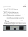
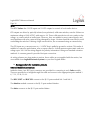
Logitek Electronic Systems ROC Reference Manual Revision 0.5 Apr 2012 Logitek Electronic Systems, Inc. 5622 Edgemoor Drive Houston, Texas 77081 USA Tel Fax 877-231-5870 +1-713-664-4470 (outside U.S. and Canada) +1-713-664-4479 Email [email protected] Web www.logitekaudio.com Contents © 2012 Logitek Electronic Systems, Inc Notice Every effort has been made to supply complete and accurate information. However, Logitek Electronic Systems, Inc. assumes no responsibility for its use, nor any infringement of patents or other rights of third parties, which would result. Worldwide rights reserved. Except for your own personal use, no part of this publication may be stored in a retrieval system, transmitted or reproduced in any way, including but not limited to photocopy, photograph, magnetic or other record, without the prior agreement and written permission of Logitek Electronic Systems, Inc. Logitek, JetStream, and ROC are trademarks of Logitek Electronic Systems, Inc. All other trademarks acknowledged. All specifications are subject to change without notice. Document Revisions Date April 2012 Revision 0.5 Author John Davis, CBNT Notes Preliminary release of ROC manual Logitek ROC Reference Manual Page 4 Contents Document Revisions.................................................................................................................... 3 Contents....................................................................................................................................... 4 1 Introduction............................................................................................................................... 7 About this Manual............................................................................................................... 7 Intended Audience.............................................................................................................. 7 Manual Conventions............................................................................................................ 7 About the ROC.................................................................................................................... 8 System Requirements........................................................................................................... 9 System Architecture ............................................................................................................ 9 Compatibility Matrix.......................................................................................................... 10 2 Unpacking................................................................................................................................ 11 Parts List............................................................................................................................ 11 Unpacking......................................................................................................................... 11 Contacting Logitek............................................................................................................. 11 3 Physical Installation................................................................................................................ 12 Power Supply Unit............................................................................................................. 12 ROC Frames...................................................................................................................... 12 ROC-F9 9 Slot Frame......................................................................................................... 12 ROC-F12 12 Slot Frame..................................................................................................... 12 ROC-F18 18 Slot Frame..................................................................................................... 13 ROC-24 Frame.................................................................................................................. 13 Meter Bridges (ROC-SMeter, ROC-LMeter)........................................................................13 Mounting........................................................................................................................... 13 Connections...................................................................................................................... 14 PSU................................................................................................................................... 15 Headphones...................................................................................................................... 15 GPIs.................................................................................................................................. 16 Internal Module Connections............................................................................................. 16 4 Configuration........................................................................................................................... 17 JetStream Configuration .................................................................................................... 17 Audio Engine Configuration............................................................................................... 17 CommandBuilder Triggers................................................................................................. 17 Device & Bus Addressing................................................................................................... 18 Logitek ROC Reference Manual Page 5 Modules............................................................................................................................ 18 Device Numbers................................................................................................................ 18 Softkey Addressing............................................................................................................. 18 Monitor Softkey Colors...................................................................................................... 21 Monitor Hotkey Addressing............................................................................................... 22 Switched Meter Addressing (Meter Bridges only)................................................................23 Meter Bridge On Air and Mic Live Tally Lamps..................................................................23 5 Operation................................................................................................................................ 24 ROC Modules.................................................................................................................... 25 ROC-FADER (Fader Module) – International (non-UK) Layout............................................25 ROC Modules.................................................................................................................... 26 ROC-FADER (Fader Module) – UK Layout.........................................................................26 ROC-MON (Monitor Module)............................................................................................ 27 Using the Change Function................................................................................................ 28 ROC-SOFT (Optional Softkey Module)...............................................................................29 6 Maintenance............................................................................................................................ 32 Warranty........................................................................................................................... 32 Firmware Updates............................................................................................................. 32 Component Replacement.................................................................................................. 32 Fader Replacement............................................................................................................ 32 Module swap-out.............................................................................................................. 34 More Assistance................................................................................................................. 34 Appendix A Release Notes......................................................................................................... 35 Known Issues..................................................................................................................... 35 Appendix B Specifications.......................................................................................................... 36 ROC Frames...................................................................................................................... 36 ROC-F9 Frame.................................................................................................................. 36 ROC-F12 Frame................................................................................................................ 36 ROC-F18 Frame................................................................................................................ 36 ROC-F24 Frame................................................................................................................ 36 ROC Modules.................................................................................................................... 36 Fader Module.................................................................................................................... 36 Monitor Module................................................................................................................ 37 Meter Bridges.................................................................................................................... 37 ROC-SMETER Meter Bridge............................................................................................... 37 Logitek ROC Reference Manual Page 6 ROC-LMETER Meter Bridge............................................................................................... 37 ROC Power Supply............................................................................................................ 37 Appendix C Pinouts.................................................................................................................... 38 To JetStream (DATA and HEADPHONES)..........................................................................38 Power Supply to Console................................................................................................... 38 GPIs.................................................................................................................................. 39 GPI Outputs...................................................................................................................... 39 GPI Inputs ........................................................................................................................ 39 Two Year Limited Warranty....................................................................................................... 40 Logitek ROC Reference Manual Page 7 1 Introduction About this Manual This manual describes the installation and operation of the Logitek ROC control surface. Intended Audience This manual is aimed at Engineers responsible for installing, configuring and supporting a Logitek Networked Console System with the ROC surface. In the context of a system installation, or to become familiar with the entire Logitek Networked Console System, the reader should also reference: JetStream Reference Manual AEConfig or JetSet Reference Manual CommandBuilder Reference Manual Manual Conventions The following conventions are used in this manual: This text indicates a menu choice to be made, with an arrow separating a multi-level selection, eg Control Panel Users & Passwords. This can be a menu choice in a Logitek application, or within Windows. Indicates a “see-also” section in this manual, or another Logitek manual. The exclamation symbol signifies an important note or critical information. This text represents a command, script block example, instruction to be typed, or directory path. Logitek ROC Reference Manual Page 8 TIP: A useful tip from our knowledge base! About the ROC The ROC control surface from Logitek Electronic Systems brings you the flexibility of a router based audio console system with the look, feel and easy handling that novice operators will understand, and experienced console operators will appreciate. The ROC offers full access to the sources available on Logitek’s JetStream routers, along with simple bus selection and intuitive monitor controls. The ROC is compatible with the Logitek Audio Engine provided that the engine has an AE-C6 card with version 3.77 or higher. The ROC surface can be configured with 6, 12, 18 or 24 Faders. There is also a Monitor Module containing the Monitoring and Selection functions and optional softkey and selector modules may be added for additional flexibility. The module types include: ROC-FADER ROC-MON ROC-SOFT ROC-SEL 6 Fader Module Monitor Control Module Additional Softkey Button Module 5 Channel Router Controller In addition, two Meter Bridges (ROC-SMeter & ROCLMeter) are available. The SMeter bridge is short; the LMeter is long. The main frame is available in a number of different sizes to accommodate the variety of fader numbers. The frame is designed to be mounted on a desk for semi-permanent installation, but as no cutouts are required it can easily be relocated. Logitek ROC Reference Manual Page 9 System Requirements ROC is designed to connect to a Logitek JetStream running DSP version 4.x. Contact Logitek Electronic Systems or your reseller if you are unsure of compatibility, or are adding a ROC surface to a pre-existing Logitek facility. System Architecture Surfaces are remote control panels for Audio Engine Audio Engines process Audio and GPI control events Surfaces Audio Engines Console Surfaces Jetstream 1 Control Panels Network switches distribute audio, control & sync Ethernet Switches Software tools provide remote control & system maintenance Client PCs Audio Network internet Remote Support Software vTools Console Surfaces Control Panels Serial Comms Business Network Jetstream 2 IP Software vTools Software vTools TCP/IP Serial TCP/IP UDP/IP Figure 1 - Logitek System Architecture (v4.x) Put simply, the ROC surface is just a remote control panel for the JetStream. Unlike traditional analog consoles, no audio passes through the ROC or its faders (with the exception of the cue speaker audio). The ROC talks to the JetStream using the Logitek Command Protocol, with all audio processing occurring inside the router.The mixing, routing and processing of audio is not dependent Logitek ROC Reference Manual Page 10 upon the embedded PC included with the JetNet Audio Networking Module. However, additional functionality, such as macro buttons, scene snapshots, intercoms, delay control and software tools interface to the system using the JetStream Server application that is bundled with the module. Compatibility Matrix ROC is designed for use with the JetStream Router v4.x and AE-32 Audio Engine v3.77 and higher. The ROC retains compatibility with other surfaces for the majority of its features. Following is the minimum software release version/date that is required for ROC support. Component JSM-DSP Controller JetStream Server CommandBuilder AEConfig JetSet General Support v1.41 v4.0 v3.6 v3.6 V1.0 Additional Features Logitek ROC Reference Manual Page 11 2 Unpacking This section details what you should do when unpacking your newly arrived ROC surface. Parts List The exact list of parts received will vary depending on your order, but should generally include: 1 x ROC Power Supply 1 x fully assembled ROC frame, containing modules as ordered 1 x meter bridge assembly (option) You will receive a parts list with the system that is specific to the modules on your order. Unpacking Carefully unpack the cartons whilst looking for any signs of shipping damage. You may wish to save the shipping cartons until the operation of the system is verified. Report any damage to the shipping carrier immediately. Verify that the contents of each box match the packing list and report any discrepancies immediately to Logitek in writing. Contacting Logitek In the event of a shipping problem, you can contact Logitek Electronic Systems in several ways: U.S. Mail Telephone Fax Email Website Logitek Electronic Systems, Inc. 5622 Edgemoor Drive Houston, Texas 77081 USA 877-231-5870 +1-713-664-4470 (outside U.S. and Canada) +1-713-664-4479 [email protected] www.logitekaudio.com International customers should contact their local authorized Logitek dealer for assistance. Logitek ROC Reference Manual Page 12 3 Physical Installation The ROC surface is designed to be mounted on a desk in a semi-permanent studio installation. The Meter Bridge, if optioned, can be screwed to the back of the ROC. Power Supply Unit The Power Supply Unit is an external supply. Power inlet is via a single IEC connector on the rear of the Power Supply Unit. A power cable is supplied only for US installations. International customers may contact their reseller for the supply of power cables if required. As the power supplies are of switch-mode type, there is no voltage selection required. ROC Frames A number of ROC frame sizes are available, depending on the total number of faders. Each module takes up either one or two “slots” in the frame. The Monitor module occupies half the slot space of a Fader module. The frame will be shipped with the modules connected and fitted as ordered. These modules are not intended to be moved, however Fader modules are interchangeable. The internal COM port connections determine the device addressing for each modules. ROC-F9 9 Slot Frame Houses 1x ROC-FADER & 1x ROC-MON 12.9” W x 14.3” D x 2.5” H (328mm x 368mm x 63mm) ROC-F12 12 Slot Frame Houses 2x ROC-FADER & 1x ROC-MON 16.8” W x 14.3” D x 2.5” H (427mm x 368mm x 63mm) Logitek ROC Reference Manual Page 13 ROC-F18 18 Slot Frame Houses 3x ROC-FADER & 1x ROC-MON 25.6” W x 14.3” D x 2.5” H (625mm x 368mm x 63mm) ROC-24 Frame Houses 4x ROC-FADER & 1x ROC-MON 33.95” W x 15.4” D x 2.6” H (862mm x 391mm x 66mm) Meter Bridges (ROC-SMeter, ROC-LMeter) Hardware LED Meter Bridges are available as an option. The Meter includes two high-resolution meters – one for Program bus and one switched (follows Monitor selection). TIP: If the ROC is powered on without being connected to the JetStream, all meter LEDs will illuminate. This is normal operation; the LEDs will turn off after being connected to the JetStream and the console begins to receive meter data. Mounting The Meter option is supplied separately and attaches to the back of the ROC frame with screws (included). The RJ-11 cable from the Meter plugs into the ROC tray card at the far right into the jack labeled “Meter.” The Meter is hinged. Gently tighten the black center screw on the rear of the hinge to lock the meter into place at the desired angle. Illustration 1: ROC-SMeter Logitek ROC Reference Manual Page 14 Connections The ROC frame contains the control circuitry for the console. It connects to the Logitek JetStream Router via a serial link. Headphone audio pass-through connectors are also provided for convenience. HP: Headphones connection. Plug a straight-through CAT-5 with RJ-45 connectors into this jack on the console to a stereo analog output on the JetStream/Audio Engine that is fed by the JetStream/Audio Engine Headphones Out mix bus. POWER: Use the supplied RJ-45 to DB-9 connector to plug the console into the Remora Power Supply. Logitek ROC Reference Manual Page 15 DATA: Use a straight-through CAT-5 with RJ-45 connectors to connect the console to the JetStream DSP card (Surface port) or Audio Engine AE-C6 card. You can use a dedicated CAT5 patch cable or existing structured cabling. If using structured cabling systems, care should be exercised to ensure the serial connections are not confused with other network outlets and that the link is not unintentionally “un-patched”. PSU The ROC is powered by an external power supply, included with the console. Connect the supply to mains using an IEC style inlet lead and the 12VDC to the rear of the ROC using the supplied DB9 to RJ-45 connection marked SURFACE. DB-15 connectors are provided on the ROC Power Supply for GPI Input and Output connections. A ground lug is provided on the chassis for your convenience. Headphones The ROC frame has a rear connection for Headphones input, which is internally wired to ¼” (6.35mm) and 1/8” (3.5mm) headphone sockets at the front. This provides for convenient headphone connection without the need to mount an in-desk or under-desk socket. Connection from the ROC to JetStream Router is via a straight-through patch cable to a JetStream JSM-AOUT-RJ analog output card, which is suitable for driving headphones directly. If connecting to a JSM-AOUT-DB card or an Audio Engine IO24A card, wiring is to the StudioHUB+ standard. See Appendix C for connector pinouts. Logitek ROC Reference Manual Page 16 GPIs The ROC Surface has 12 GPI inputs and 12 GPI outputs for control of local studio devices. GPI outputs are driven by optically-isolated, non-polarized, solid state switches, rated at 500ma to a maximum voltage of 24V AC/DC, with surge to 2A. These solid state devices do not conduct at low voltage, so cannot switch an audio input. However, they are suitable for most control signals, and avoid problems with relay contacts being damaged by surges. Caution should be exercised to avoid overloading the switches. If driving a high current device, we recommend using an external relay. The GPI inputs are a current source to +3.3VDC that is pulled to ground to activate. This makes it suitable for control by push-button, relay or open collector. A diode protects against static and over voltage up to 18V. See the wiring diagram for polarity information if using non-standard activation methods. A common ground is provided for input connection. As wiring schemes vary from station to station, these cables are not supplied with the surface, but are available from Logitek Electronic Systems or your local Logitek dealer. See Appendix C for connector pinouts. Internal Module Connections Inside the frame, four RJ11 port connectors are provided for connecting to each Fader module. These are provided as a straight-through flat cable and connect to the appropriate ports marked 16, 7-12, 13-18, 19-24. The ROC-SOFT and ROC-SEL connect to the RJ-11 ports marked Soft 1 and Soft 2. The Monitor module connects to the RJ-11 port marked Monitor. The Meter connects to the RJ-11 port marked Meter.. Logitek ROC Reference Manual Page 17 4 Configuration This chapter covers basic configuration information, relating specifically to the ROC surface. JetStream setup and configuration is covered in detail in the following manuals: Logitek JetStream Reference Manual Logitek AEConfig Reference Manual JetStream Configuration Configuration of the JetStream Router is done in JetSet. See the JetStream Reference Manual for information on configuring JetStreams Audio Engine Configuration Configuration of the Audio Engine is done in AE Config. Currently, AEConfig does not include specific DSP table entries for the ROC. You should use a Mosaic surface of the appropriate size when configuring a ROC. In the future, specific ROC support will be added to AEConfig, however, the two consoles are compatible in DSP allocations. Ignore the entries for ROC-5 and ROC-10; those are used in the 1990's era ROC console. See the Audio Engine Reference Manual for information on configuring Audio Engines. CommandBuilder Triggers The ROC surface contains many programmable buttons and features. These features are scripted in “triggers” in CommandBuilder, and executed by JetStream Server, which is included with the JetNet Audio Networking Module. See the CommandBuilder User’s Manual for information on writing Triggers. Logitek ROC Reference Manual Page 18 The CommandBuilder manual includes details and examples of ROC specific features, such as Monitor Hotkeys, Softkey Buttons and more. The programming of these features does require a certain level of familiarity with the system. If you need assistance, please contact Logitek Electronic Systems or your reseller. Device & Bus Addressing Each device (such as a fader input or button panel) requires its own Device Number. Within that device, each button, lamp and feature has a Bus Number. Together, the Device and Bus Numbers allow the JetStream and Surface to communicate. When configuring the ROC’s programmable buttons in CommandBuilder, you will require the Device Number and Bus Number for each button or lamp. The information below will help you determine the addressing scheme in use on your ROC. Modules Module ROC-MON ROC-FADER ROC-METER How Addressing is determined Uses the standard Monitor, Headphones, Guest/Studio & Cue Gain addressing Device Set determined by COM port allocation (pre-defined) Uses standard PGM Meter addressing Max Modules Supported 1 4 modules (24 faders) 1 Device Numbers In ROC v1.x the Device Number of a module is determined by its firmware and position. Softkey Addressing The twelve softkeys on the monitor module follow the Numix Bridge Button addressing scheme, therefore the Bridge Button and Bridge Lamp keywords in Command Builder may be used. The softkey buttons for a console connected to JetStream port 1 are on device 28 and the lamps are on device 27. For port 2, use device 50 for buttons and 4F for lamps. For port 3, use device 64 for buttons and 63 for lamps. Bus numbers are 32-43. For example, button #1 on a console connected to JetStream port 1 is device 28 bus 32 and its corresponding lamp is device 27 bus 32. Alternatively, it is valid to address button #1 on Logitek ROC Reference Manual Page 19 port 1 as surf 1 bridgebutton 1 and its corresponding lamp as surf 1 bridgelamp 1. Command Builder will translate those keywords into the appropriate device and bus numbers. Logitek ROC Reference Manual Page 20 Port 1 – Button device 28/lamp device 27 Button 1 2 3 4 5 Bus 32 33 34 35 36 Port 2 – Button device 50/lamp device 4F Button 1 2 3 4 5 Bus 32 33 34 35 36 Port 3 – Button device 64/lamp device 63 Button 1 2 3 4 5 Bus 32 33 34 35 36 6 7 8 9 10 11 12 37 38 39 40 41 42 43 6 7 8 9 10 11 12 37 38 39 40 41 42 43 6 7 8 9 10 11 12 37 38 39 40 41 42 43 Logitek ROC Reference Manual Page 21 Monitor Softkey Colors The 12 monitor softkeys may be set to any of 256 RGB colors. The colors may be set through assembly language commands or keywords in Command Builder. Logitek ROC Reference Manual Page 22 Monitor Hotkey Addressing There are four monitor hotkeys that may be addressed in Command Builder to route sources to the control room monitors, headphones, and studio monitors. The buttons are labeled SEL1, SEL2, SEL3, and SEL4. Illustration 2: Monitor Hotkeys SEL 1 is bus 16. SEL 2 is bus 17. SEL 3 is bus 18, and SEL4 is bus 19. The device numbers are as follows: Port Number Monitor Headphones Studio 1 Device 24 Device 25 Device 23 2 Device 4C Device 4D Device 4B 3 Device 62 Device 65 Device 61 Alternatively, d[device] notation in Command Builder, such as d[Port1 Monitor In] is valid and will be properly translated by Command Builder. Logitek ROC Reference Manual Page 23 Switched Meter Addressing (Meter Bridges only) The Switched meter defaults to displaying whatever source is routed to Monitor In. When bus 0 is turned on for the Monitor Meter in device, the meter will switch to whatever source is routed to the Monitor Meter In. Monitor Meter In Device Numbers: Port (Surface) Number Device Number 1 2c 2 54 3 6a In Command Builder, sources should be routed to d[Port1 Monitor Meter In] (or appropriate port number) using the Alt+D pick list. Command Builder will translate this into the appropriate hex device number. Meter Bridge On Air and Mic Live Tally Lamps Two tally LEDs are provided on the ROC-SMETER and ROC LMETER. The Mic Live tally may be used to tell the operator that the mic is on. The On Air tally may be used to tell the operator that the console has been switched to air. The bus number of the Mic Live LED is 17 and the On Air LED is 18. The device numbers are in the chart below. Device Numbers for Mic Live and On Air Tally Lamps Port (Surface) Number Device Number 1 28 2 4F 3 63 Because these LEDs are on the same device number as console GPI outputs, an easy way to program the Mic Live lamp is to enter 117 into the Mute Tally box for each Mic on port 1. For port 2 consoles, use 217. For port 3 consoles, use 317. Logitek ROC Reference Manual Page 24 5 Operation Your Logitek ROC console has been designed for easy and quick access to the functions you most need. If you’ve had experience with broadcast consoles before, you’ll soon be at home, finding your way around quite easily. Logitek Electronic Systems has been manufacturing broadcast consoles for decades, so we understand how to make control surfaces that are both powerful and straightforward. During the design of the ROC, customers and operators provided feedback that helped shape the final product. So we’re confident you’ll find the ROC a joy to use on-air. Following is a look at each of the ROC modules, and how the standard functions are used. Logitek ROC Reference Manual Page 25 ROC Modules ROC-FADER (Fader Module) – International (non-UK) Layout CNG – Change button. Press to route a new source to this fader. Use the select knob on the monitor module to scroll through the sources on the OLED display below the fader. Press Take on the monitor module to select the source; Cancel to clear change mode. Change mode will also automatically turn off after 5 seconds of inactivity. TB/Soft button – This button turns on bus 14 for the fader. By default, if a source with a mix minus bus is routed here, the talkback mic will be sent to the mix minus. If no mix minus bus is associated with the source, a trigger may be written in Command Builder to perform another function when the button is pressed. Cue button – Press to listen to the source through the internal cue speaker regardless of fader position or whether the channel is on or off. P button – Program bus select. Press to send this channel to the program mixing bus. The lamp on the button will illuminate to show whether the bus is assigned or not. The lamp will glow at half brightness when the channel is off and full brightness when the channel is on. A1 button – Aux 1 bus select. Press to send this channel to the Aux 1 mixing bus. The lamp on the button will illuminate to show whether the bus is assigned or not. The lamp will glow at half brightness when the channel is off and full brightness when the channel is on. A2 button – Aux 2 bus select. Press to send this channel to the Aux 2 mixing bus. The lamp on the button will illuminate to show whether the bus is assigned or not. The lamp will glow at half brightness when the channel is off and full brightness when the channel is on. A3 button – Aux 3 bus select. Press to send this channel to the Aux 3 mixing bus. The lamp on the button will illuminate to show whether the bus is assigned or not. The lamp will glow at half brightness when the channel is off and full brightness when the channel is on. Fader – Adjusts level for the selected mixing busses. OLED Display – Text shows channel assignment. A pre-fader meter appears below the text. Turns fader on Turns fader off Logitek ROC Reference Manual Page 26 ROC Modules ROC-FADER (Fader Module) – UK Layout CNG – Change button. Press to route a new source to this fader. Use the select knob on the monitor module to scroll through the sources on the OLED display below the fader. Press Take on the monitor module to select the source; Cancel to clear change mode. Change mode will also automatically turn off after 5 seconds of inactivity. TB/Soft button – This button turns on bus 14 for the fader. By default, if a source with a mix minus bus is routed here, the talkback mic will be sent to the mix minus. If no mix minus bus is associated with the source, a trigger may be written in Command Builder to perform another function when the button is pressed. P button – Program (Desk) bus select. Press to send this channel to the program mixing bus. The lamp on the button will illuminate to show whether the bus is assigned or not. The lamp will glow at half brightness when the channel is off and full brightness when the channel is on. A1 button – Aux 1 bus select. Press to send this channel to the Aux 1 mixing bus. The lamp on the button will illuminate to show whether the bus is assigned or not. The lamp will glow at half brightness when the channel is off and full brightness when the channel is on. A2 button – Aux 2 bus select. Press to send this channel to the Aux 2 mixing bus. The lamp on the button will illuminate to show whether the bus is assigned or not. The lamp will glow at half brightness when the channel is off and full brightness when the channel is on. A3 button – Aux 3 bus select. Press to send this channel to the Aux 3 mixing bus. The lamp on the button will illuminate to show whether the bus is assigned or not. The lamp will glow at half brightness when the channel is off and full brightness when the channel is on. Fader – Adjusts level for the selected mixing busses. Turns channel on and off when raised from infinity. OLED Display – Text shows channel assignment. A pre-fader meter appears below the text. Machine Start PFL (Pre Fader Listen) Logitek ROC Reference Manual Page 27 Use the SELECT wheel to change the input selection on the Fader or Monitoring source after pressing the CNG (Change) button. Winding the SELECT wheel will cycle through the available inputs, displaying on the relevant screen. Press TAKE to accept, or CANCEL to cancel the change. 12 Softkey buttons are user programmable and are commonly used for intercoms, delay control, and snapshot/recall functions. A special command in Command Builder can toggle these buttons between softkeys and use as a numeric keypad. The SPLIT button switches the headphones to put the monitored source in left and CUE (UK: PFL) in right. The DIM button reduces the volume of the control room monitors when pressed. Use the CNG buttons to access the source change function for each of the monitoring destinations. The OLED screen displays the current source for each monitoring send. When the relevant CNG button is pressed, you can scroll through the selection list to select a new source. While a fader is in change mode, use the COMP button to access Compressor settings, EQ button to access EQ settings, MAIN button to access Pan and Mode settings, and MISC button to access miscellaneous settings on the meter bridge. Press and turn the 1, 2, and 3 knobs to navigate the menu on the meter bridge. The RST button resets and the RUN button starts the timer on the meter bridge. The TB RETURN knob controls the level of incoming audio from other studio intercoms. The CUE knob controls the cue audio level (labeled as PFL in the UK). Use the TB button to talk back to the guest headphone/studio monitor output. This button activates bus 14 on Studio In (port 1 device 23, port 2 device 4B, port 3, device 61) Four hotkey buttons are available for headphones, monitor, and guest/studio for quck access to common sources. Turn the HEADPHONES, MONITOR or STUDIO gain knobs to increase (clockwise) or decrease (anticlockwise) the level going to the relevant monitoring send. Logitek ROC Reference Manual Page 28 Using the Change Function When you press Change over a fader, the select portion of the Monitor Module reacts as follows in the following modes: Main The change function always defaults to this mode. Press the Main button to return to this mode from another mode if desired. Turn the red Select knob to change the source over a fader. Press Take to confirm. The monitor module will light up with 3 additonal options in three columns on the meter bridge under the monitor meter: Trim, pan (balance), and mode. Turn the green knob that corresponds with the column to adjust each control. Press Take to confirm. The green LED will light next to each active green knob when there is something that you are allowed to change. If the trim, pan, and mode controls do not light up, those functions have been locked out in the JetStream or Audio Engine configuration software. Comp (Compression/Limiting) Press the Comp button to enter this mode while change is active. Several pages of compressor controls are available in this menu displayed under the monitor meter on the meter bridge. Use the red Select knob to change pages. Turn the green knob that corresponds with the column (left, center, right) to adjust the settings displayed on the meter bridge. Press the right hand knob to set compression IN or OUT as desired. If Allow Effects is not set to Yes for the source in the JetStream/Audio Engine configuration software, this menu will be completely turned off. EQ (Equilization) Press the EQ button to enter this mode while change is active. Several pages of EQ controls are available, and the red Select knob changes the pages displayed under the monitor meter on the meter bridge. Turn the green knob that matches the column. Press the far right green knob to set EQ IN or OUT as desired. If Allow Effects is not set to yes for the source, the menu will be completely turned off. MISC (Miscellaneous) Reserved for future use. Currently, pressing this button sends change mode back to Main. Logitek ROC Reference Manual Page 29 ROC-SOFT (Optional Softkey Module) For customers who need more than 12 softkeys, Logitek offers an expansion softkey module. Two expansion ports are available for any combination of ROC-SOFT and ROC-SEL modules. The buttons are addressed in Command Builder by device number and bus number. The device number corresponds to the port inside the ROC tray where the module is connected. The bus number corresponds to the button on the module. There are separate device numbers for lamp and switch so they may be addressed separately. In addition, the device numbers are different depending upon which surface port the console is connected to on the JetStream or Audio Engine. The matrix below will help you determine the correct device number. (expressed in hexadecimal format) AE/JSM Port Expansion 1 Lamp Expansion 1 Switch Expansion 2 Lamp Expansion 2 Switch 1 2d 2e 2f 30 2 55 56 57 58 3 Use a fader port Use a fader port Use a fader port Use a fader port Logitek ROC Reference Manual Page 30 Illustration 3: Softkey Expansion Module Connections on ROC Tray The Bus numbers are shown on the following page. Logitek ROC Reference Manual Page 31 Logitek ROC Reference Manual Page 32 6 Maintenance The ROC uses multi-layer boards with surface mount technology. As such, the majority of the console is not user-serviceable. However, there are some basic tasks that can be performed by suitably qualified technical personnel. Warranty Logitek Electronic Systems will honor the warranty of the system when conducting field maintenance, provided: Repairs or updates only relate to recommended and documented procedures Care is taken and procedures are followed Repairs are conducted by suitably trained or experienced service personnel If you do not feel comfortable performing maintenance or repairs, please do not proceed. If you would like advice prior to attempting a repair, please contact Logitek Electronic Systems or your reseller. Firmware Updates Each module strip has internal memory that is field upgradeable. Logitek Electronic Systems or your local Logitek dealer may from time-to-time supply firmware updates to add new features or fix bugs. Component Replacement The ROC uses standard faders which can be replaced by station technicians. Fader Replacement The ROC uses a Penny & Giles fader. Model No. PGF3210/D/U/--A Logitek ROC Reference Manual Page 33 No audio is carried through the fader, just control signals. The fader can be easily replaced with a spare from Logitek or an electronics supplier. Illustration 4: Underside of the ROC-FADER To replace a fader: Logitek ROC Reference Manual Page 34 1. Remove the four screws from the required module. 2. Carefully remove the module from the frame. 3. Disconnect the fader from the main board. 4. Remove the slider cap. 5. Remove the two hex screws that mount the fader to the module. 6. Fit the replacement fader to the module using the two hew screws. 7. Replace the slider cap. 8. Reconnect the fader connector, ensuring the same polarity as the other faders on the module. 9. Replace the module in the frame, and screw it back in. Module swap-out If you need to swap a module with an on-site spare, you can simply unscrew the module, disconnect it, connect the replacement and screw it in. Modules are fully hot-swappable – they will refresh their status shortly after powering up. More Assistance If you would like more assistance with maintenance and service, please contact Logitek or your reseller. Logitek ROC Reference Manual Page 35 Appendix A Release Notes Known Issues The following issues have been reported and are under investigation. Logitek ROC Reference Manual Page 36 Appendix B Specifications ROC Frames ROC-F9 Frame Houses 1x ROC-FADER & 1x ROC-MON 12.9” W x 14.3” D x 2.5” H (328mm x 368mm x 63mm) ROC-F12 Frame Houses 2x ROC-FADER & 1x ROC-MON 16.8” W x 14.3” D x 2.5” H (427mm x 368mm x 63mm) ROC-F18 Frame Houses 3x ROC-FADER & 1x ROC-MON 25.6” W x 14.3” D x 2.5” H (625mm x 368mm x 63mm) ROC-F24 Frame Houses 4x ROC-FADER & 1x ROC-MON 32.4” W x 14.3” D x 2.5” H (823mm x 368mm x 63mm) ROC Modules Fader Module No of faders Features 6 The Fader Module provides the following features: LED-illuminated on/off and control start/stop buttons Penny & Giles 100 mm long throw faders Dedicated controls for four bus assigns Softkey button for talkback or other user-defined function Yellow OLED display capable of displaying 16 character source names and pre-fader meter Available in standard (International) or U.K. configurations Logitek ROC Reference Manual Page 37 Monitor Module Features The Monitor Module provides the following features: Contains controls for main monitor, cue speaker, operator headphone, studio monitor and guest headphone Studio, Monitor, and Operator Headphones each have 4 input select hotkey buttons 12 programmable softkeys Multifunction select knob for input selection, EQ, mode, pan and dynamics adjustment Yellow OLED screen displays 16-character source names Available in standard (International) or U.K. configurations Meter Bridges ROC-SMETER Meter Bridge Dimensions Features The Narrow Meter Bridge provides the following features: One 27-LED stereo bar graph meters simultaneously showing peak and VU levels 2 LCD screens for metering and text LED indicators for studio and microphone tally OLED display for naming the meter source ROC-LMETER Meter Bridge Dimensions Features The Narrow Meter Bridge provides the following features: One 27-LED stereo bar graph meters simultaneously showing peak and VU levels LCD screen for metering and text LED indicators for studio and microphone tally OLED display for naming the meter source ROC Power Supply Voltage 110 - 230 VAC, automatically selected Frequency 47 - 63 Hz Consumption 40 W maximum Logitek ROC Reference Manual Page 38 Appendix C Pinouts To JetStream (DATA and HEADPHONES) Connection to the JetStream is via a RJ45 connector mounted on the rear of the frame. Straight through CAT5 cabling is used. Pin 1 2 3 4 5 6 7 8 Connection Cue Cue + RS485 RXRS485 TXRS485 TX+ RS485 RX+ No connect Ground Power Supply to Console Connection between the power supply and console is DB-9 to RJ-45 RJ-45 DB-9 Pin 1 2 3 4 5 6 7 8 Connection Pin 1 2 3 4 5 6 7 8 9 Connection Logitek ROC Reference Manual Page 39 GPIs GPI connections are on two DB25 connectors on the power supply. One DB-25 is for inputs and one is for outputs. We recommend terminating GPIs to Krone style (or similar) termination blocks. GPI Inputs Pin 1 2 3 4 5 6 7 8 9 10 11 12 13 Connection GPI In 1 GPI In 2 GPI In 3 GPI In 4 GPI In 5 GPI In 6 GPI In 7 GPI In 8 GPI In 9 GPI In 10 GPI In 11 GPI In 12 No Connect GPI Outputs Pin 14 15 16 17 18 19 20 21 22 23 24 25 Connection Ground Ground Ground Ground Ground Ground Ground Ground Ground Ground Ground Ground Pin 1 2 3 4 5 6 7 8 9 10 11 12 13 Connection GPI Out 1A GPI Out 2A GPI Out 3A GPI Out 4A GPI Out 5A GPI Out 6A GPI Out 7A GPI Out 8A GPI Out 9A GPI Out 10A GPI Out 11A GPI Out 12A No Connect Pin 14 15 16 17 18 19 20 21 22 23 24 25 Connection GPI Out 1B GPI Out 2B GPI Out 3B GPI Out 4B GPI Out 5B GPI Out 6B GPI Out 7B GPI Out 8B GPI Out 9B GPI Out 10B GPI Out 11B GPI Out 12B Two Year Limited Warranty Logitek Electronic Systems, Inc. warrants its professional equipment (excluding Logitek Software, which is covered by a separate warranty) against defects in materials and workmanship for two years pursuant to the following terms and conditions. The warranty extends to the original purchaser only. LOGITEK will repair or replace, at its option, at its factory without charge professional equipment if a defect in materials or workmanship develops during the first two years following purchase, when the equipment is returned to the factory or LOGITEK authorized service centers freight prepaid with a description of the nature of the failure. No reimbursements can be made for repair charges that are not factory authorized. After repair or replacement, LOGITEK will return the equipment to the purchaser freight prepaid. In the event that any part of this professional equipment becomes defective during the first two years following purchase, and purchaser wishes to attempt repair, purchaser may obtain a replacement part by notifying LOGITEK of the part of the equipment which has failed. LOGITEK will thereafter ship a replacement part, freight prepaid. LOGITEK may require the purchaser to return the defective part to LOGITEK freight prepaid as a condition of such replacement, either before or after LOGITEK ships the replacement part. LOGITEK shall not be responsible for any other charges or liabilities associated with purchaser-made repairs. No part or equipment shall be considered defective if it fails to operate due to exposure to extreme temperatures or excessive moisture in the atmosphere. Light bulbs, batteries, potentiometers or other equipment not manufactured by Seller shall carry only the warranty, if any, of the original equipment manufacturer in effect at the time of shipment of this order; and Seller’s obligation under this warranty shall be limited to such adjustment as Seller may obtain from the original manufacturer. This limited warranty is void if equipment is modified or repaired without authorization; subjected to misuse, abuse, accident, water damage or other neglect; or has had its serial number defaced or removed. No obligation is assumed by LOGITEK to update previously manufactured equipment. Specifications are subject to change without notice. EXCEPT AS SPECIFICALLY PROVIDED HEREIN, LOGITEK MAKES NO WARRANTY, REPRESENTATION, PROMISE, OR GUARANTEE, EITHER EXPRESS OR IMPLIED, STATUTORY OR OTHERWISE, WITH RESPECT TO THE EQUIPMENT, USER DOCUMENTATION OR RELATED TECHNICAL SUPPORT, INCLUDING THEIR QUALITY, PERFORMANCE, MERCHANTABILITY OR FITNESS FOR A PARTICULAR PURPOSE. IN NO EVENT WILL LOGITEK BE LIABLE FOR INDIRECT, SPECIAL, INCIDENTAL, TORT, ECONOMIC, COVER, OR CONSEQUENTIAL DAMAGES ARISING OUT OF THE USE OF OR INABILITY TO USE LOGITEK PRODUCTS, EQUIPMENT, OR SERVICES, INCLUDING, WITHOUT LIMITATION, DAMAGES OR COSTS RELATING TO THE LOSS OF PROFITS, BUSINESS, GOODWILL, DATA OR COMPUTER PROGRAMS, EVEN IF ADVISED OF THE POSSIBILITY OF SUCH DAMAGES. IN NO CASE SHALL LOGITEK ‘S LIABILITY FOR MONEY DAMAGES EXCEED THE AMOUNT PAID BY YOU FOR THE LOGITEK EQUIPMENT OUT OF WHICH SUCH CLAIM AROSE. THE FOREGOING LIMITATIONS SHALL NOT APPLY TO CLAIMS RELATING TO DEATH OR PERSONAL INJURY WHICH ARISE OUT OF PRODUCTS DEEMED TO BE CONSUMER GOODS UNDER APPLICABLE LAW. Some states or provinces do not allow the exclusion or limitation of implied warranties or limitation of liability for incidental or consequential damages, so the above exclusion or limitation may not apply to you. The warranty and remedies set forth herein are exclusive and in lieu of all others, oral or written,express or implied. No Logitek dealer, distributor, agent, or employee is authorized to make any modification or addition to this warranty.