1
Contents
Getting Started with TempDAQ
GETTING STARTED WITH TEMPDAQ ........................................ 2
Hardware Setup
Software setup
Thank you for purchasing TempDAQ. This analog breakout
box allows your existing CarDAQ2534 or CarDAQ-Plus
hardware to measure up to 6-channels of temperature data
or analog voltages.
USING TEMPDAQ ................................................................................ 4
Connecting Sensors
Measuring Temperatures
Measuring Voltages
TempDAQ measures a temperature range -200OC to +1250OC
better than 1OC of resolution. CarDAQ2534 users, please
contact DrewTech about a factory-upgrade (0.1% tolerance
resistors) which improves accuracy from 2OC to better than
1OC. This change is already present for CarDAQ-Plus.
DEVELOPING CUSTOM APPLICATIONS .................................... 6
PassThruIoctl (GET_CONFIG and SET_CONFIG)
PassThruIoctl (READ_ANALOG_CH1 … CH6)
PassThruIoctl (READ_CH1_VOLTAGE … CH6)
Your package includes: the TempDAQ hardware, an interface
cable, and a CD including sample programs and source code.
Please visit the DrewTech website for manual or software
updates.
TROUBLESHOOTING AND SUPPORT .......................................13
Hardware Setup
SPECIFICATIONS AND CONNECTORS .....................................14
Analog Connector (TempDAQ)
Analog Connector (CarDAQ2534)
Analog Connector (CarDAQ-Plus)
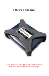
Connect TempDAQ to CarDAQ2534’s analog port using the
included interface cable. Verify that the red power LED on the
rear panel lights when connected to a powered CarDAQ.
NOTICES ABOUT TESTING AND CERTIFICATION..............16
Statements
United States
European Union
Note: If the power light is off, check the serial number of
CarDAQ2534. Any CarDAQ2534 before serial number 1656
(Rev J) requires a factory-performed upgrade. Please contact
DrewTech for further information.
Powering CarDAQ
Remember that your PC cannot provide CarDAQ2534 with
power over its RS-232 or Ethernet ports. There are three
options for powering the CarDAQ2534:
1. Attached to a vehicle: The vehicle supplies power on
pin 16 of its OBD-II (SAE J1962) connector. CarDAQ is
powered whenever it is connected to a vehicle.
2
2. Signal breakout box: Using the DrewTech J1962 to
banana jack adapter, apply between +6 to +15 VDC at
the Vbatt (pin 16) terminal. Use ChGnd (pin 4) for
reference.
3. Custom harness: Using the CarDAQ connector kit
(available upon request), build a custom wiring
harness. Refer to pin diagrams in the CarDAQ2534
manual for details.
Software setup
Install the CarDAQ driver software normally; all TempDAQ
functionality is provided through cardaq32.dll, and no
additional configuration is required for TempDAQ features.
Sample programs and source code are available on the
DrewTech website, and on the CD included in this package.
Using TempDAQ
TempDAQ is a temperature compensated amplifier that
reads voltage from K-type thermocouples, and scales it to 027V so CarDAQ can use the full dynamic range of its A/D
subsystem. It also provides BNC inputs to read 0-27v range
signals.
Connecting Sensors
The TempDAQ™ supports up to 6-channels of analog input,
using K-type thermocouple or BNC connectors.
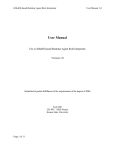
Connect either a BNC or K-type thermocouple to the
appropriate channel on TempDAQ’s front panel. Then choose
the appropriate input: set the switch up for thermocouple, or
down for BNC input.
Measuring Temperatures
The TempDAQ CD includes source code and a sample
program AnalogDemo.exe for reading temperatures. Run
this program to verify that the sensors and hardware have
been connected properly.
TempDAQ scales and offsets a K-type thermocouple’s
voltage so CarDAQ can use its A/D dynamic range. Given
that the PassThruIoctl functions return a voltage (mV),
calculate the thermocouple’s voltage output (mV) using the
following equation:
VTC = (VCARDAQ – 6125) / 393.9;
NIST provides inverse approximations for temperature as a
function of voltage (mV) for K-type thermocouples. The
functions are of the form:
Temp = dO + d1VTC + d2VTC2 + … + dNVTCN
3
4
The AnalogDemo source code implements this inverse
approximation in function tempC(). Refer to the NIST ITS-90
tables if you wish to implement your own conversion
functions.
Measuring Voltages
TempDAQ does not scale voltages on the BNC inputs. The
PassThruIoctl functions return the actual voltage (mV)
present at the BNC.
Developing Custom Applications
CarDAQ is fully compliant with the PassThru (SAE J2534) API,
which protects your investment in developing custom
software. This syntax and set of driver functions allows a
software application to discover and use any vendor’s
PassThru hardware, with any modern automotive diagnostic
protocol.
Since temperature and voltage measurement is currently
unique to DrewTech, we provide vendor-specific extensions
to the PassThruIoctl function.
DrewTech’s j2534_v0202.h file defines several
PassThruIoctl modes for reading temperature data:
Ioctl Mode
pInput
pOutput
READ_ANALOG_CH1 … CH6
NULL
ulong*
READ_CH1_VOLTAGE
CH6
NULL
ulong[]
…
new
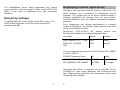
There are two new parameters for PassThruIoctl SET_CONFIG
and GET_CONFIG:
SCONFIG Parameter Name
ID
Value
ADC_READINGS_PER_SECOND
0x10000
Rate in Hz
ADC_READINGS_PER_SAMPLE
0x20000
# Averages
DrewTech also offers a complete set of LabVIEW VIs for
CarDAQ2534, with native datatypes and context-sensitive
help. Please contact DrewTech for information about using
TempDAQ with LabVIEW.
5
6
See Also
PassThruIoctl (GET_CONFIG and
SET_CONFIG)
PassThruIoctl (READ_ANALOG_CH1 … 6)
Example
Syntax
SCONFIG param[10];
SCONFIG_LIST list;
#include "j2534_v0202.h"
long PassThruIoctl(unsigned long ChannelID, unsigned long
IoctlID, SCONFIG_LIST *pInput, NULL);
param[0].Parameter = ADC_READINGS_PER_SECOND;
param[0].Value = 10;
Description
list.NumOfParams = 1;
list.ConfigPtr = param;
The PassThruIoctl function is a general purpose I/O control
function for modifying the vehicle network interface
characteristics. TempDAQ defines two new parameters to
configure the ADCs on an existing logical communications
channel:
RetVal = PassThruIoctl(ChannelID, SET_CONFIG, &list, NULL);
ADC_READINGS_PER_SECOND is the total number of
voltage readings each second (Hz) for all 6 channels.
ADC_READINGS_PER_SAMPLE specifies the number
of voltage readings to average for each sample.
Usually, set this to 1.
The A/D sampling rate is equal to the number of readings
per second divided by the number of readings per sample.
Parameters
ChannelID
Logical communication channel identifier
IoctlID
GET_CONFIG or SET_CONFIG
pInput
Pointer to list of parameters to read, or parametervalue pairs to set.
pOutput
NULL
7
8
int num = 20;
PassThruIoctl (READ_ANALOG_CH1 …
CH6)
RetVal = PassThruIoctl(ChannelID, READ_ANALOG_CH1, &num,
values);
if (RetVal != STATUS_NOERROR)
{
PassThruGetLastError(errstring);
printf("Reading ADC failed! Code %d (%s)\n", RetVal,
errstring);
exit(1);
}
Syntax
#include "j2534_v0202.h"
long PassThruIoctl(unsigned long ChannelID, unsigned long
IoctlID, void *pInput, void *pOutput);
Description
The PassThruIoctl function is a general purpose I/O control
function for modifying the vehicle network interface
characteristics. TempDAQ extends this function to read
temperature information.
This mode returns all buffered samples (mV) on a specific
ADC channel (1 to 6) since the previous call.
Parameters
ChannelID
Logical communication channel identifier
IoctlID
pInput
READ_ANALOG_CH1, …, READ_ANALOG_CH6
Requested number of ADC samples to read. If not
enough samples are available, function returns actual
number read.
pOutput
Pointer to array where requested A/D samples (mV)
will be copied.
See Also
PassThruIoctl (GET_CONFIG and SET_CONFIG)
Example
// Request 20 ADC samples in mV
unsigned long values[20];
9
10
RetVal = PassThruIoctl(ChannelID, READ_CH1_VOLTAGE, NULL,
&value);
if (RetVal != STATUS_NOERROR)
{
PassThruGetLastError(errstring);
printf("Reading ADC failed! Code %d (%s)\n", RetVal,
errstring);
exit(1);
}
PassThruIoctl (READ_CH1_VOLTAGE …
CH6)
Syntax
#include "j2534_v0202.h"
long PassThruIoctl(unsigned long ChannelID, unsigned long
IoctlID, void *pInput, void *pOutput);
// For TempDAQ, find thermocouple value in degC
voltage = (value - 6125) / 393.9;
temp = tempC(voltage);
Description
The PassThruIoctl function is a general purpose I/O control
function for modifying the vehicle network interface
characteristics. TempDAQ extends this function to read
temperature information.
This ioctl mode returns the most recent sample (mV) on a
specific ADC channel (1 to 6), and flushes all other samples
currently in the queue.
Parameters
ChannelID
Logical communication channel identifier
IoctlID
READ_ANALOG_CH1, …, READ_ANALOG_CH6
pInput
NULL
pOutput
Pointer to unsigned long where most recent value
(mV) will be copied. Following this call, buffered
samples will be flushed.
See Also
PassThruIoctl (GET_CONFIG and SET_CONFIG)
Example
// Read the most recent ADC sample in mV
11
12
Troubleshooting and Support
Specifications and Connectors
DrewTech is available 9:00am to 5:30pm eastern standard
time, Monday through Friday, to answer any questions.
Please email [email protected] if you need assistance.
If TempDAQ Doesn’t Power-on or Read Inputs
If the power light is on, verify that the front panel is selecting
the correct input: thermocouple or BNC.
If the power light is off, check the serial number of
CarDAQ2534. Any CarDAQ2534 before serial number 1656
(Rev J) requires a factory-performed upgrade. Please contact
DrewTech for further information.
TempDAQ (Rev. A) Specifications:
Name
Input Voltage Range
Operating
Temperature
Value
6VDC to 15VDC
Commercial Range (0OC to +70OC)
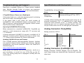
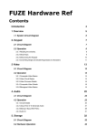
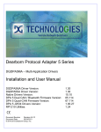
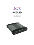
CarDAQ utilizes Switchcraft’s EN3 weather-tight series for all
external connections. Pin 1 is indicated by a small bump
inside the male connector at the “11 o’clock” position. The
remaining pins are in a counter-clockwise pattern, with the
last pin in the center for the six and eight pin connectors.
Improving CarDAQ2534 A/D Accuracy
When connected to a standard CarDAQ2534, TempDAQ can
measure a wide temperature range with 2OC accuracy and
1OC resolution.
Analog Connector (TempDAQ)
A factory-performed CarDAQ2534 upgrade is available (0.1%
tolerance resistors) which improves accuracy to better than
1OC. Please contact Drewtech for further information.
Your CarDAQ contains field-upgradeable firmware. Updates
are regularly released which: include new features, improve
performance, and correct problems. Please visit DrewTech’s
download page at:
Pin #
1
2
3
4
5
6
7 to 14
15
http://www.drewtech.com/downloads
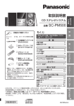
Analog Connector (CarDAQ2534)
Apply power to CarDAQ. Run J2534install.exe, similar to a
new installation, to install the new J2534 DLL on the PC.
Then, run cardaq_setup.exe to reprogram CarDAQ with the
new firmware.
Mating connector: EN3C8F (DigiKey P/N SC1164-ND). The
male image below was obtained from Switchcraft’s product
data sheet.
Updating CarDAQ’s Drivers and Firmware
13
Mating connector: DB-15F
14
Function
Channel 1
Channel 2
Channel 3
Channel 4
Channel 5
Channel 6
Ground
Battery Voltage
Direction
Out
Out
Out
Out
Out
Out
In
Notices about Testing and Certification
CarDAQ’s 12-bit analog inputs are setup for an input range
of 0 to 27.5VDC and electrically protected against reverse
voltage and over voltage conditions.
Pin #
1
2
3
4
5
6
7
8
Function
Channel 1
Channel 2
Channel 3
Channel 4
Channel 5
Channel 6
Battery Voltage
Ground
Additional details are provided here.
Direction
In
In
In
In
In
In
Out
Statements
Our equipment is marketed only to the automotive and
related industries.
Users of our equipment are intended to be qualified
engineers and technicians.
Our equipment
environment.
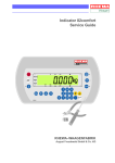
Analog Connector (CarDAQ-Plus)
Mating connector: Male D-Sub High Density 15 (Digikey P/N
T815M-ND).
Pin #
10
14
4
8
5
2
6
1, 3, 5, 7, 9, 11,
13, 15
Function
Channel 1
Channel 2
Channel 3
Channel 4
Channel 5
Channel 6
Battery Voltage
GND
Drew Technologies equipment is designed and built using
best commercial practices. None of our equipment is
subjected to any kind of compliance testing nor is the
equipment certified to meet any particular requirements with
regards to EMI, EMC, ESD, or others. This applies to all of
our products unless specified otherwise.
Direction
In
In
In
In
In
In
Out
is intended for
use
in
an
industrial
Our equipment is intended to be test equipment.
Our equipment requires integration with other test
equipment to function. At a minimum a computer and a 'unit
under test' are required. The 'unit under test' may be a
module, several modules, an entire motor vehicle, or similar
test set-up.
Our equipment is not intended for use by consumers or in a
consumer environment.
We do not sell to individual consumers.
United States
The governing body is the FCC (Federal Communications
Commission).
15
16
Point #1
Point #1
The controlling law is Title 47, Code of Federal Regulations,
Part 15 "Radio Frequency Devices".
The governing Directive is: EMC Directive (89/336/EEC
including all amendments). We do not test our equipment to
meet this directive. (See Point #3, below.)
We state that our equipment is classified as a: "Class A
Digital Device." We cite 47 CFR, Part 15, Subpart A, section
15.3 "Definitions", paragraph (h): "Class A digital device. A
digital device that is marketed for use in a commercial,
industrial or business environment, exclusive of a device
which is marketed for use by the general public or is
intended to be used in the home."
Additionally, our equipment is considered an un-intentional
radiator.
We state that our equipment is exempt from the certification
requirements of Part 15. We cite 47 CFR, Part 15, Subpart B,
section 15.103 "Exempted Devices", paragraph (c): "A digital
device used exclusively as industrial, commercial, or medical
test equipment."
We do not test our equipment to meet any requirements of
47 CFR Part 15.
Point #2
The governing Directive is: Low Voltage Directive (73/23/EEC
including all amendments). We do not test our equipment to
meet this directive. (See Point #3, below.)
Point #3
Our equipment can only be sold and exported to EU
customers under very narrow terms. Our equipment has no
intrinsic function (it requires other equipment with which to
work). Our equipment is considered a component of a larger
equipment item or system. The customer is responsible for
integrating our equipment into their equipment or system.
The customer is responsible for all subsequent testing and
certification of the resulting equipment or system.
All questions should be addressed to: Engineering Dept.,
Drew Technologies, Inc.
Point #2
The controlling law is Title 47, Code of Federal Regulations,
Part 18 "Industrial, Scientific, and Medical Equipment".
We cite 47 CFR, Part 18, Subpart A, section 18.115
"Elimination and investigation of harmful interference". The
user assumes responsibility for eliminating the source of
harmful interference.
European Union
The governing body is the European Community (and its
various bodies).
17
18