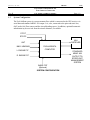
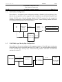
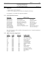
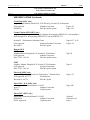
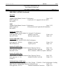
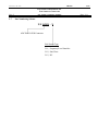
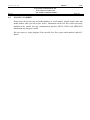
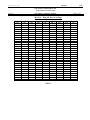
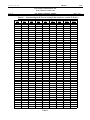
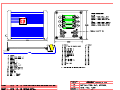
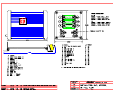
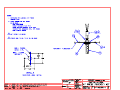
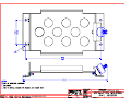
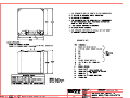
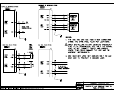
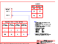
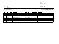
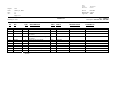
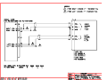
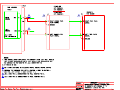
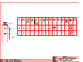
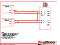
1
FUEL/AIRDATA COMPUTER (ADC 2000) P/NS: 962830-1, 962830-2, 962830-3 INSTALLATION MANUAL REV L © Shadin 6831 Oxford Street St. Louis Park, MN 55426 USA Sales: (800)-328-0584 Technical Support: (800)-388-2849 www.shadin.com P/N: IM2830 IM2830 IM2830LG.doc, DIR. 962830 Shadin INSTALLATION MANUAL FUEL/AIRDATA COMPUTER P/N 962830-1, 962830-2, 962830-3 Rev: L Page: i of vi PAGE CONTROL CHART SECTION NO. 1.0 DESCRIPTION PAGE REVISION LOG vi OVERVIEW 1.1 1.2 1.3 1.4 1.5 2.0 The Manual Product Information System Configuration Fuel Totalizer Configuration F/ADC2000, Argus Moving Map Configuration 2.6 2.7 2.8 2.9 Input Data Range Output Data Range Dimensions Power Requirements Output Data 2.5.1 Serial Output Data Parameters 2.5.2 ARINC 429 (GAMA) Output Labels 2.5.3 ARINC 429 Labels Associated with Switch Settings 2.5.4 ARINC 429 Labels Associated with Switch Settings Limitations 2.6.1 Warm-up Time 2.6.2 Supplemental Equipment 2.6.3 Static/Pitot Source Error Correction (SSEC/PSEC) 2.6.4 SSEC/PSEC Listing 2-1 2-1 2-1 2-1 2-2 2-2 2-2 2-4 2-5 2-6 2-6 2-6 2-6 2-7 Part Numbering Scheme Electrical Interface Specifications 2.8.1 Heading Interface 2.8.2 Fuel Flow Interfaces 2.8.2.1 Digital Fuel Flow 2.8.2.2 Sine Wave Fuel Flow 2.8.2.3 DC Voltage Fuel Flow 2.8.3 Baro Interface Statistical Specifications 2.9.1 Mean Time Between Failures 2-11 ⏐ Indicates change since previous revision H | J | 1-1 1-1 1-2 1-3 1-3 FUEL AND AIRDATA SYSTEM SPECIFICATIONS 2.1 2.2 2.3 2.4 2.5 REV 2-12 2-12 2-12 2-13 2-13 2-13 2-14 IM2830 IM2830LG.doc, DIR. 962830 Shadin INSTALLATION MANUAL FUEL/AIRDATA COMPUTER P/N 962830-1, 962830-2, 962830-3 Rev: L SECTION NO. DESCRIPTION Page: ii of vi PAGE REV 3.0 CERTIFICATION 3-1 F| 4.0 PLACING AN ORDER 4-1 F| 5.0 INSTALLATION PROCEDURE 5.1 5.2 5.3 5.4 5.5 5.6 5.7 5.8 5.9 5.10 General F/ADC Location Selection Mounting the F/ADC Mounting the OAT Probe Connection to the Fuel Flow Sensor Connection to the Heading Source Connection to the Pitot and Static Lines Connection to the Navigation Management System Connection to the Altimeter Baro Pot (optional) Post Installation Checkout J | 5-1 5-1 5-1 5-2 5-3 5-4 5-5 5-6 5-6 5-6 6.0 OPERATING INSTRUCTIONS 6-1 F | 7.0 INITIALIZATION 7-1 F | 8.0 MAJOR COMPONENTS OF THE SYSTEM 8-1 H | ⏐ Indicates change since previous revision IM2830 IM2830LG.doc, DIR. 962830 Shadin INSTALLATION MANUAL FUEL/AIRDATA COMPUTER Rev: L SECTION NO. 9.0 P/N 962830-1, 962830-2, 962830-3 DESCRIPTION CONFIGURING THE AIRDATA 9.1 9.2 10.0 PAGE Configuring with ‘ADSETUP User Manual’ Configuring Manually Loopback Procedure 1 for S/W Version 93.00.16 - 93.00.29 Stage 0 Loopback Configuration Stage 1 Loopback Configuration Loopback Procedure 2 for S/W Version 93.00.51 – 93.00.71 Stage 0 Loopback Configuration Stage 1 Loopback Configuration Stage 2 Loopback Configuration Stage 3 Loopback Configuration Loopback Procedure 3 for S/W Version 93.00.77 Stage 0 Loopback Configuration Stage 1 Loopback Configuration Stage 2 Loopback Configuration Stage 3 Loopback Configuration Loopback Procedure 4 for S/W Version 93.00.82 + Stage 0 Loopback Configuration Stage 1 Loopback Configuration Stage 2 Loopback Configuration Stage 3 Loopback Configuration Stage 4 Loopback Configuration Select No Delay J | 9-1 9-2 9-3 9-3 9-4 9-6 9-6 9-7 9-9 9-10 9-11 9-11 9-12 9-14 9-15 9-16 9-16 9-17 9-19 9-20 9-21 9-22 SETTING THE K-FACTOR Setting the K Factor Table 1 - Analog K-Factor Settings Table 1 Table 2 - Digital K-Factor Settings Table 2 (Matrix 0) Table 2 - Digital K-Factor Settings Table 2 (Matrix 0) Table 2 - Digital K-Factor Settings Table 2 (Matrix 0) Table 3 - Alternate Digital-K Factor Setting Table 3 (Matrix 1) ⏐ Indicates change since previous revision Page: iii of vi REV G | 10-1 10-2 10-3 10-4 10-5 10-6 IM2830 IM2830LG.doc, DIR. 962830 Shadin INSTALLATION MANUAL FUEL/AIRDATA COMPUTER P/N 962830-1, 962830-2, 962830-3 Rev: L 11.0 Page: iv of vi INSTALL DRAWINGS AND INSTALL KITS PARTS LISTS Drawing No. Description/Part Number DATE 4028-394 Installation DWG, ADC2000, Digital Fuel Flow P/N 962830-1 3/21/05 E | 4028-431 Installation DWG, ADC2000, Sine Fuel Flow P/N 962830-2 3/21/05 D | 4028-432 Installation DWG, ADC2000, DC Fuel Flow P/N 962830-3 3/21/05 D | 4028-005 Installation DWG, OAT Probe Assembly Kit P/N 681201-1 2/14/05 C 4028-395 Installation, Mounting Tray, ADC2000 3/03/05 B | 4070-005 Installation Dwg, Serial to Argus 5000/7000 Converter P/N 937000-03 2/14/05 B | 4028-423 Installation Wiring, Fuel/Airdata Computer (ADC2000) to Fuel System 3/11/03 B | 4028-425 Installation Wiring, Fuel/Airdata Computer (ADC2000) to OAT/Heading System 2/14/05 A | 4028-944 Installation Wiring, Loop-Back Harness for F/ADC200, 2000, D-Sub Connector 2/14/05 B | 4028-945 Installation Wiring, F/ADC200, 2000 to Navigational Receivers with ARINC 429 Installation Wiring, F/ADC200, 2000 to Navigational Receivers with RS-422, RS-485 3/11/03 A | 3/11/03 A | 4028-947 Installation Wiring, F/ADC200, 2000, Shadin Fuel Flow Indicators to Bendix/King Nav Receiver 3/11/03 A | 4028-948 Installation Wiring, F/ADC200, 2000 and Shadin Converter to Eventide Argus 2/14/05 A | 4028-A80 Label, ADC200/2000 Access Cover, P/N 712801 2/14/05 A | 4028-A82 Installation Wiring, ADC 2000, D-Sub Connector to Altimeter Baro Pot 3/11/03 C | 4028-B94 Installation Wiring, F/ADC200, 2000, Shadin Fuel Flow Indicators to Garmin 430/530 3/11/03 A | N/A Parts List, OAT Probe Assembly Kit P/N 681201-1 2/14/05 G | N/A Parts List, ADC2000 Installation Kit P/N IK9630-1 3/21/05 A | 4028-946 ⏐ Indicates change since previous revision REV | IM2830 IM2830LG.doc, DIR. 962830 Shadin INSTALLATION MANUAL Rev: L 11.0 FUEL/AIRDATA COMPUTER P/N 962830-1, 962830-2, 962830-3 Page: v of vi INSTALL DRAWINGS AND INSTALL KITS PARTS LISTS (continued) Drawing No. Description/Part Number DATE REV AIRCRAFT SPECIFIC 4028-818 Installation Wiring, F/ADC-200, 2000 w/Analog FF to Beech KingAir Indicators 3/11/03 B | 4028-819 Installation Wiring, F/ADC200, 2000 Sine FF to Mitsubishi MU-300 & Model 400 Beechjet 2/14/05 B | 4028-909 Installation Wiring, ADC200/2000 to Mitsubishi MU-2 w/Foxboro PC-620 System 2/14/05 B | 4028-936 Installation Wiring, F/ADC200, 2000 or DigiData with DC FF to Cessna Citation 500, 501, 550, S550, 551, 552 2/14/05 A | 4028-937 Installation Wiring, F/ADC200, 2000 or DigiData with DC FF to Cessna Citation 525 Jet 2/14/05 A | 4028-938 Installation Wiring, F/ADC200, 2000 or DigiData with Digital FF to BomBardier LearJet 24, 25D 1/17/05 A | 4028-939 Installation Wiring, F/ADC200, 2000 with Sine FF to Rockwell Commander 690 and 695 2/14/05 A | 4028-940 Installation Wiring, F/ADC200, 2000 or DigiData with DC FF to Raytheon Beechjet 400A Aircraft 2/14/05 A | 4028-941 Installation Wiring, F/ADC200, 2000 or DigiData with DC FF to Westwind 1124 Models 2/14/05 A | 4028-942 Installation Wiring, F/ADC200, 2000 to Fairchild SA226 Series Aircraft 1/17/05 A | 4028-943 Installation Wiring, F/ADC200, 2000 to Navigational Receivers with RS-232 1/17/05 C | 4028-949 Installation Wiring, F/ADC200, 2000 to Aerospatiale AS365N2 Dauphin 2/14/05 A | 4028-950 Installation Wiring, F/ADC200, 2000 to Aerospatiale AS332 Super Puma 2/14/05 A | 4028-A29 Installation Wiring, F/ADC-200, 2000 or DigiData with DC FF Piper Cheyenne PA31T 1/17/05 C | ⏐ Indicates change since previous revision IM2830 IM2830LG.doc, DIR. 962830 Shadin INSTALLATION MANUAL FUEL/AIRDATA COMPUTER P/N 962830-1, 962830-2, 962830-3 Rev: L Page: vi of vi REVISION LOG REV – A B C D E DATE 6/8/95 9/12/95 6/9/97 6/13/97 6/23/97 1/8/98 APP’D SES SES KCL KCL KCL KCL F 12/17/98 KCL G 7/26/00 EDJ H 9/13/00 EDJ J 11/03/00 KCL K 6/27/02 EDJ L 3/21/05 WMP CHANGE Baseline release Miscellaneous updates 4 Stage loop back procedure report to 4028C; Expand index Correct manual rev Revise limitations section Miscellaneous updates, format change Added new sections 5.9, 5.10, Switch 4 table page 9-10, Special Options page 9-11, updated table 1 page 10-2, updated Dwg 4028-944 and included Dwg’s 4028-A29, 4028-A80, and 4028-A82, and new parts list IK9630-1 Added Bendix B & Garmin 430/530 Format G to page 9-7, Added one more Ragen Indicator / Transmitter to page 11-32. Added Garmin 430/530 to page 1-1. Added ARINC Label 234 & 235 to page 2-4. Changed OAT Install kit to 681201A-1 on page iii. Changed pages 11-11, -13, -16, -21, & -29. Added Allied Signal to page 2-5. Moved Raytheon Hawker HS125-3A to page 2-9. Added 2nd AN816 fitting to page 5-5. Changed page iv to reflect change to 4028-943. Page iii and 1-3 changed to include Dwg # 4028-B94. Page 2-1 changed for OAT tolerance, IVS to 10,000 fpm, and Pitot & IAS set to 20 knots for low speed. Page 2-4 and 2-5 changed to clarify configuration A parameters. Page 5-4 changed to include Sandel heading source. Page 9-1, 9-2, 9-6, and 9-7 changed to clarify software version useage. Page 9-11 moved to 9-16. Pages 9-11 to 9-15 added for Procedure 3. Page 5-1 changed to add TSO paragraph. Add sections 2.8 and 2.9. Update sections 2.0, 5.1, 5.7 and 9.2. Moved page 9-16 to 9-21. Included updated Dwg 4028-A82. Corrected typo in section 1.3 system figure. Added 681201 OAT probe installation and parts list to page iv drawing list. Updated Page 2-4 ARINC table. Corrected page 10-3 Table 2. Added pages 9-21 to 9-26. Page 9-21 became 9-27. Changed “Shadin Company Inc.” and “SCI” to “Shadin” everywhere. Updated rev levels of cited documents. Removed loopback procedure for S/W Version 93.00.79 . From §2.5.3, removed unsupported ARINC 429 Label 247. From §11.0 Install Drawings and Install Kits Parts Lists, removed 4012-177 and PL, 681201A-1. Updated Aerosonic altimeter, 10420-11968E replacing 102220-1188. ⏐ Indicates change since previous revision IM2830 IM2830LG.doc, DIR. 962830 Shadin INSTALLATION MANUAL FUEL/AIRDATA COMPUTER P/N 962830-1, 962830-2, 962830-3 Rev: H 1.0 OVERVIEW 1.1 The Manual Page: 1-1 This manual is designed to facilitate the installation of the Shadin Fuel/AirData Computer (ADC 2000). 1.2 Product Information The Shadin ADC 2000 system is designed to provide a combined source of fuel and air data. Listed below are the navigational systems that the ADC 2000 has been designed to be compatible with. Receives Serial Data from: Magellan Skynav 5000 ARNAV STAR 5000 FMS 7000 R5000 Trimble 2000/2000A 2100/3000 3100/2101 Bendix King KLN90 KLN90A KLN90B KLN89/89B Garmin BFGoodrich IIMorrow 150, 155, 155XL, 165 Pronav LNS 6000 611, 612, 618 230, 230XL NMS 2001 300, 300XL 800, 820, 360 430/530 GX50, 55, 60 Transmits Serial Data to: ARNAV Magellan Note: To find out which particular receiver Bendix/King Trimble models have Airdata receive capability, contact Garmin the manufacturers. Transmits ARINC Data to: ASINC Bendix King Airshow EFIS 40/50 Global GNSX GNS-Xls Trimble TNL8100 Honeywell SPZ-5000 Data Nav III Universal UNS-1M IIMorrow 2101 Garmin 430/530 IM2830 IM2830LG.doc, DIR. 962830 Shadin INSTALLATION MANUAL FUEL/AIRDATA COMPUTER Rev: H 1.3 P/N 962830-1, 962830-2, 962830-3 Page: 1-2 System Configuration The Fuel/AirData system is a remote mounted box which is connected to the GPS receiver via serial data and standard ARINC 429 output. It is, also, connected to the pitot and static line, OAT probe, fuel flow sensors and the aircraft heading source. In addition, optional barometric information my be received from the aircraft altimeter, if available. PITOT STATIC NAV RECEIVER OAT MAG. HEADING FUEL/AIRDATA COMPUTER L. ENGINE F/F STANDARD ARINC 429 OUTPUT TO EFIS/FLIGHT MANAGEMENT SYSTEM R. ENGINE F/F BARO POT (Optional) SYSTEM CONFIGURATION IM2830 IM2830LG.doc, DIR. 962830 Shadin INSTALLATION MANUAL FUEL/AIRDATA COMPUTER Rev: H 1.4 Page: 1-3 P/N 962830-1, 962830-2, 962830-3 Fuel Totalizer Configuration Shown below is an optional system configuration utilizing a Shadin Fuel Flow Indicator. Note that the only navigational receiver supported in this configuration are the Bendix/King KLN and Garmin 430/530 series. Consult Drawing Number 4028-947 contained in this manual for installation information for the Bendix/King KLN series. Consult Drawing Number 4028-B94 for installation information for the Garmin 430/530. Garmin Bendix/King 430, 530 KLN90, A, B KLN89 KLN900 Shadin RS-232 DigiFlo MiniFlo MicroFlo L. Fuel Flow Transmitter R. Fuel Flow Transmitter or Shadin RS-232 1.5 F/ADC200 F/ADC2000 RS-232 F/ADC2000, Argus Moving Map Configurations. Shown below is the system configuration that supports output to a Eventide Argus moving map using the Shadin serial to serial data converter P/N 937000-03. The fuel and airdata are displayed on the Eventide-Argus moving map. Consult Drawing numbers 4070-005 and 4028-948 contained in section 11. Shadin RS-232 or RS422 F/ADC2000 RS-232 or RS422 Shadin Navigational Receiver RS-232 Converter P/N 937000-03 Eventide Argus Moving Map P/N 5000 P/N 7000 IM2830 IM2830LG.doc, DIR. 962830 Shadin INSTALLATION MANUAL FUEL/AIRDATA COMPUTER P/N 962830-1, 962830-2, 962830-3 Rev: J 2.0 FUEL AND AIRDATA SYSTEM SPECIFICATIONS 2.1 Input Data Range Pitot Static OAT Heading Fuel Flow K Factor 2.2 Output Data Range PARAMETER IAS P.ALT P.ALT P.ALT P.ALT OAT HEADING IVS TAS MACH WIND SPEED WIND DIRECTION FUEL FLOW 2.3 20 to 350 kts. -1000 to 55,000 ft. -60°C to, +60°C 0 - 360° 1 to 450 GPH Range Selected 500 to 130000 PPG Continuous Accuracy ±1 kts. ±25 ft. ±30 ft. ±40 ft. ±100 ft. ±2°C ±1° ±40 ft./min. ±2 kts. ±.01 ±1 kts. ±5° ±2% RANGE 20 to 350 kts. –1000 to 5000 ft. 5000 to 11000 ft. 11000 to 30000 ft. 30000 to 55000 ft. –60°C to +60°C 0 - 360 degrees ± 10,000 ft./min. 20 - 600 kts. .2 - .95 5 - 360 kts. 0 - 360 degrees 1 - 450 GPH Dimensions (including mounting rack) Size: 7.4" L x 4.3" H x 3.9" W Weight: 36 oz. 2.4 Power Requirements System Power required: 28 VDC @ 1300 mA 14 VDC @ 900 mA Page: 2-1 IM2830 IM2830LG.doc, DIR. 962830 Shadin INSTALLATION MANUAL FUEL/AIRDATA COMPUTER Rev: J 2.5 Page: 2-2 P/N 962830-1, 962830-2, 962830-3 Output Data 1. Electric Format: RS-422 or RS-232 2. ARINC 429 low/high speed GAMA (Has to be configured at the factory) See paragraph 2.5.3 for ARINC 429 output data capabilities. 2.5.1 Serial Output Data Parameters Fuel Group Left Fuel Flow Right Fuel Flow Fuel Used Total Total Fuel Used Fuel Used Right Fuel Used Left Fuel Remaining NM/Gal (ground) Fuel to Destination Fuel at Destination AirData Group Aircraft Type MACH Number True Air Speed (TAS) Indicated Air Speed (IAS) Wind Direction and Speed Vertical Speed True Air Temperature Outside Air Temperature (OAT) Density Altitude Drift Angle Magnetic Heading Baro Pressure Baro Corrected Alt Pressure Altitude Rate of Turn Baro Correction (mb #1) Baro Correction (hg ”) Note: Not all parameters will be available to all navigational receivers. Contact the manufacturer for display capabilities. 2.5.2 ARINC 429 (GAMA) Output Labels * LABEL# 074G 075G 113G 114 115 116 117G 147G 150 162 163 203 204 205 206 TYPE DSC DSC BNR BNR BNR BNR BNR BNR BNR BNR BNR BNR BNR BNR BNR RATE mS 100 100 100 50 50 50 50 1000 1000 200 1000 200 200 200 200 LABEL NAME Flight Plan Header Active WPT from/to WPT Group Checksum Desired Track (T) WP Bearing (T) Crosstrack Distance Vertical Deviation Magnetic Variation GMT Density Altitude Wind on Nose PALT (1013.25 mB) PALT (Baro Corrected) Mach Number IAS IM2830 IM2830LG.doc, DIR. 962830 Shadin INSTALLATION MANUAL FUEL/AIRDATA COMPUTER Rev: J P/N 962830-1, 962830-2, 962830-3 LABEL# 210 211 212 213 234 235 251G 252 275G 301G 302G 303G 304G 305G 306G 307G 310 311 312 313 314 315 316 320 321 347 351G 352G TYPE BNR BNR BNR BNR BNR BNR BNR BNR DSC BNR BNR BNR BNR BNR BNR BNR BNR BNR BNR BNR BNR BNR BNR BNR BNR BNR BNR BNR RATE mS 200 200 200 200 100 100 200 200 200 100 100 100 100 100 100 100 200 200 50 50 100 100 100 100 100 100 200 200 Page: 2-3 LABEL NAME True Airspeed OAT IVS TAT (Static) Baro Correction (mb #1) Baro Correction (mg”) Distance to Go Time to Go LRN Status Flags Message Character 7-9 Message Character 10-12 Message Length/Type/Number Message Character 1-3 Message Character 4-6 NAV/WPT/AP Latitude NAV/WPT/AP Longitude Present Position Latitude Present Position Longitude Ground Speed Track Angle (T) True Heading (T) Wind Speed Wind Angle (T) Magnetic Heading (M) Drift Angle Left and Right Fuel Flow Distance to Destination Estimated Time to Destination * Not all labels are available at the same time. Certain sets of labels are available depending on the switch selections. IM2830 IM2830LG.doc, DIR. 962830 Shadin INSTALLATION MANUAL FUEL/AIRDATA COMPUTER Rev: J 2.5.3 Page: 2-4 P/N 962830-1, 962830-2, 962830-3 ARINC 429 Labels Associated with Switch Settings LABEL Description 0 074 075 100 113 114 115 116 147 203 204 205 206 210 211 212 213 234 235 244 251 252 275 300 303 304 305 306 307 310 311 312 313 314 315 316 320 321 347 351 352 * ** *** # Flight Plan Header Active Waypoint To/From Selected Course Waypoint Group Checksum Desired Track (True) Waypoint Bearing (True) Cross Track Distance Magnetic Variation PALT (1013.25 mB) PALT (Baro Corrected) MACH Indicated Airspeed (IAS) True Airspeed OAT Vertical Speed (IVS) TAT (Static) Baro Correction (mb #1) Baro Correction (Hg “) Total Fuel Flow Distance To Go Time To Go LRN Status Word Navigation Aid Info Waypoint Group Header Message ID Characters 1-3 Message ID Characters 4-6 Waypoint Latitude Waypoint Longitude Present Latitude Present Longitude Ground Speed True Track True Heading Wind Speed Wind Direction (True) Magnetic Heading Drift Angle (True) Left/Right Fuel Flow Distance to Final Destination Time to Final Destination 1 2* 3 O O 4 5 6 7 8** 9*** A# O O O O O O B C D E F Configuration 2 sends all labels at a 50 msec rate for Flight Visions HUD. Configuration 8 sends all labels at a 100 msec rate for Collins FMS 800. Configuration 9 sends all labels at a 50 msec rate for MkVII GPWS. Configuration A sends all labels at a 50 msec rate for Mk VI and VIII EGPWS. Only available w/ARINC software version 71.73.01 and above. IM2830 IM2830LG.doc, DIR. 962830 Shadin INSTALLATION MANUAL FUEL/AIRDATA COMPUTER Rev: J 2.5.4 P/N 962830-1, 962830-2, 962830-3 Page: 2-5 ARINC 429 Labels Associated with Switch Settings 0 - Honeywell SPZ-5000 for Cessna 1 - Bendix KLN90B or Global GNSXC(LS) 2 - HUD-Heads Up Display for Flt Visions 3 - UNS1 4 - EFIS40/50 5 - ASINC Airshow Cabin Display 6 - Trimble 8100 (No label 275) 7 - TNL-8100 8 - Collins FMS 800 (100 ms rate) 9 - Mk VII GPWS (50 ms rate) A - Mk VI & VIII (50 mSec rate) Note that 3 and 6 are the same except for label 275. The following is a list of the different switch settings that the ARINC switch may be set to. The ARINC switch position is shown in section 9.2. 0 - 1 - Long Range Nav function of Honeywell SPZ-5000 Flight Guidance/EFIS System installed on the Cessna Citation Jet Aircraft. Bendix to Global/Cabin Info System installed on the Cessna Citation Jet Aircraft. 2 - Reserved 3 - 8100, UNS1 4 - Bendix/King EFIS 40/50 5 - ASINC Airshow 6 - 7 - 8100, UNS1, except no label 275. Use when there is no serial navigation data being received by the ADC2000. TNL-8100, with total fuel flow label 244 8 - Collins FMS 800 (100 ms rate) 9 - Allied Signal, Mk VII GPWS (50 ms rate) A* - Allied Signal, Mk VI & VIII (50 ms rate) * for ARINC software version 71.73.01 and up IM2830 IM2830LG.doc, DIR. 962830 Shadin INSTALLATION MANUAL FUEL/AIRDATA COMPUTER Rev: J 2.6 P/N 962830-1, 962830-2, 962830-3 Page: 2-6 Limitations 2.6.1 Warm-up time The Fuel/AirData System requires a warm-up time that varies with ambient temperature: 70°C ambient 15°C ambient -20°C ambient -40°C ambient 5 minutes warm-up required 10 minutes warm-up required 15 minutes warm-up required 20 minutes warm-up required If the ADC has been configured for a fuel flow delay, fuel flow and thus fuel used information shall be unavailable at startup for the duration of the selected delay. 2.6.2 Supplemental equipment All Shadin F/ADC(s) and ADC(s) are not designed to replace factory installed airdata fuel flow systems or other gauges. They are not intended to be used as a primary system to drive altimeters or airspeed indicators. The F/ADC fuel section is not a fuel quantity system and therefore reports only what was manually entered by the operator. 2.6.3 Static Source Error Correction (SSEC), Pitot Source Error Correction (PSEC) For certain models of aircraft, the Fuel/Airdata System will make corrections to pressure altitude by compensating for static source error. For some of these models, the Fuel/Airdata System will make corrections to indicated airspeed by compensating for pitot source error. The System does not provide true and absolute readings for all circumstances. It makes no altitude corrections when the uncorrected IAS is below 100 knots, and it makes no airspeed corrections when the uncorrected IAS is below 150 knots. It does not account for other factors, such as the current useful weight, that contribute to static source error and pitot source error. Rather, the Fuel/Airdata System performs calculations based solely on indicated airspeed and pressure altitude. The SSEC / PSEC corrections were derived from specific aircraft data referred to in section 2.6.4. To configure the Shadin F/ADC for a specific aircraft model refer to section 9. IM2830 IM2830LG.doc, DIR. 962830 Shadin INSTALLATION MANUAL FUEL/AIRDATA COMPUTER Rev: J Page: 2-7 P/N 962830-1, 962830-2, 962830-3 2.6.4 SSEC/PSEC LISTING Beechcraft Beechjet-400 (SSEC only) Airplane Flight Manual, BeechJet 400, Section 6, Performance FAA approved 1/86 Altitude Correction Revision A9 14/92 Copilot System Boeing 707-321B Advanced SSEC Airplane Flight Manual, Boeing 707, Section IV, Performance FAA approved 3/27/69, D6-1588 Altitude Calibration Revision 2/4/69 Pilot & Copilot PSEC Airplane Flight Manual, Boeing 707, Section IV, Performance FAA approved 9/20/66, D6-1588 Airspeed Calibration Pilot & Copilot Page 6-14 Figure 6-8 Page 19 FLAPS UP Page 18 FLAPS UP Cessna 500 (SSEC only) Airplane Flight Manual, Cessna/Citation Model 500, Section IV, Performance FAA approved Aug 7/74 Altitude Correction Figure 4-7 Revision 53 - Dated 11 Dec 85 Pilot & Copilot system Page 4-17.1 Cessna 501 (SSEC only) Airplane Flight Manual, Cessna/Citation I SP Model 501, Section IV, Performance FAA approved Altitude Correction Figure 4-5 Original Pilot & Copilot system Page 4-15 NOTE: Uses same Hardware configuration as Cessna 500 Cessna 525 (SSEC only) Airplane Flight Manual Model 525 Altitude Correction Pilot & Copilot system Rept FT525-4 Page 47 Cessna 550 (SSEC only) Airplane Flight Manual, Cessna/Citation II Model 550, Section IV, Performance FAA approved Altitude Correction Figure 4-5 Original Pilot & Copilot system Page 4-15 Cessna 560 (SSEC only) Airplane Flight Manual, Model 560, S/N 259 & Below, Section IV, Performance FAA approved Altitude Correction Figure 4-5 Original Pilot & Copilot system Page 4-17 IM2830 IM2830LG.doc, DIR. 962830 Shadin INSTALLATION MANUAL FUEL/AIRDATA COMPUTER Rev: J Page: 2-8 P/N 962830-1, 962830-2, 962830-3 SSEC/PSEC LISTING (Continued) Cessna 560 (SSEC only) Airplane Flight Manual, Model 560 , S/N 260 & Up, Section IV, Performance FAA approved Altitude Correction Figure 4-5 56FMA-00 Pilot & Copilot system Page 4-19 Cessna Citation S550 (SSEC only) Airplanes -0115 through -0160 Except Airplanes Incorporating SBS550-32-7 and Airplanes 0001 through-0114 Incorporating SBS550-32-1 but not SBS550-32-7. Section IV - Performance, Standard Charts FAA approved Altimeter Position Correction Revision 37 Pilot & Copilot Douglas DC-8 SSEC Airplane Manual, Douglas DC-8, Section IV, Performance FAA approved Altitude Correction DAC-33161 10/1/66 Pilot & Copilot system PSEC Airplane Manual, Douglas DC-8, Section IV, Performance FAA approved Airspeed Correction DAC-33161 10/1/66 Pilot & Copilot system Falcon 10 (SSEC only) Airplane Flight Manual, Section 6. Performance, 7 Position Error FAA approved 10/17/73 Position Error Revision 14, 6/6/78 Pilot & Copilot Falcon 20-C, D, E (SSEC only) Maintenance Instruction Manual, 34-18-03 Sept 1/77 Altitude Correction CS-143 Copilot system Falcon 20-F (SSEC only) Maintenance Instruction Manual, 34-18-03 DTM30528 Altitude Correction DGAC Approved Copilot system Pages 4-17, 4-18 Figure 4-5 Page 20 Page 11 Page 6-27 Page A48 Section 5 Subsection 20 Page 4 IM2830 IM2830LG.doc, DIR. 962830 Shadin INSTALLATION MANUAL FUEL/AIRDATA COMPUTER Rev: J P/N 962830-1, 962830-2, 962830-3 Page: 2-9 SSEC/PSEC LISTING (Continued) Falcon 50 SSEC Airplane Flight Manual, Section 5. Performance Page 5.25.2 DGAC approved Copilot (for A/C equipped with one ADC) Revision 24 PSEC Airplane Flight Manual, Section 5. Performance Page 5.25.2 DGAC approved Pilot (normal) and Copilot MACH Indicators Revision 24 LearJet 24 (SSEC only) Airplane Manual, LearJet Model 24, Section IV, Performance FAA approved 3/17/66 Altitude Correction Revised 7/19/68 Pilot & Copilot system Figure 4-10 Page 4-16 LearJet 25D (SSEC only) Airplane Manual, LearJet 25D/F AFM, Performance FAA approved 10/14/86 Altitude Correction FM-018 Release A Copilot system Figure 5-10 Page 5-18 LearJet 35 (SSEC only) Flight Manual, LearJet 35, Normal System, Flaps up, Gear up Page 5-18 FAA approved, 4/30/76 Altitude Position Correction Figure 5-10 Reissued 2/25/81 Pilot’s Altimeter- STBY & Copilot’s Altimeter LearJet 55 (SSEC only) Gates LearJet 55, APM, Performance Data, Flaps up, Gear up FAA approved, 3-17-81 Altitude Position Correction Change 13 Page 5-20 Figure 5-11 Lockheed Jetstar (SSEC only) Airplane Flight Manual, Performance Data, Weight = 32,000 Lb., Clean Configuration: Leading Edge Flaps up, Trailing Edge Flaps up, Landing Gear up Page 4-25 FAA approved, 12/14/76 Altimeter Installation Correction Figure 4-15 IM2830 IM2830LG.doc, DIR. 962830 Shadin INSTALLATION MANUAL FUEL/AIRDATA COMPUTER Rev: J Page: 2-10 P/N 962830-1, 962830-2, 962830-3 SSEC/PSEC LISTING (Continued) Mitsubishi MU-300 (SSEC only) Airplane Flight Manual, Diamond IA, Section 6, Performance FAA approved Jan 11/84 Altitude Correction Copilot system Figure 6-8 Page 6-20 Raytheon Hawker HS-125-3A (SSEC only) Airplane Manual, Document No. H.S.1.10 Static Position Error CAA Approved Correction to Altimeter Section 5 Figure 5-4 Page 13 Raytheon Hawker HS125-700A (SSEC only) 125 Crew Manual, First Officer, Section 2, Flaps Retracted Correction to Altimeter Revision :G, 4/77 Page 2-30 Static Position Figure 6 Sabreliner 60 (SSEC only) Sabreliner Pilot’s Manual, SR 75-064, Weight = 16,000 Lb. 9/1/76 Altitude Calibration Figure 7-2 Sabreliner 65 (SSEC only) Pilots Manual, SR-78-028 Altitude Correction Pilot & Copilot system Westwind 1124A (SSEC only) Airplane Flight Manual, 1124A , Section V, Performance CAA approved Altitude Correction Figures 5-13, Flaps 0 Copilot system NOTE: Gross Weight averaged at 18,750 lbs. Figures 7-1 through 7-5 265-65-7-31,32A,33 Pages V-25 IM2830 IM2830LG.doc, DIR. 962830 Shadin INSTALLATION MANUAL FUEL/AIRDATA COMPUTER Rev: J 2.7 P/N 962830-1, 962830-2, 962830-3 Part Numbering Scheme P/N 962830 - X ADC2000 D-SUB Connector Fuel Sensor Type X=1, Frequency/Level Interface X=2, Sine Wave X=3, DC Page: 2-11 IM2830 IM2830LG.doc, DIR. 962830 Shadin INSTALLATION MANUAL FUEL/AIRDATA COMPUTER Rev: J 2.8 P/N 962830-1, 962830-2, 962830-3 Page: 2-12 Electrical Interface Specifications The specifications for the interfaces heading, fuel flow and baro are listed in this section. 2.8.1 Heading Interface The heading interface follows the ARINC 407 standard (line voltage of 11.8 Vrms). Synchro Leg H X Y 2.8.2 Input Impedance 10 kohm 17 kohm 17 kohm Fuel Flow Interfaces There are three basic types of fuel flow interfaces supported. The interface type is defined in the ADC2000 part number. Refer to section 2.7 for the part numbering scheme. 2.8.2.1 Digital Fuel Flow Interface The are two possible installations for the digital fuel flow interface, the first is that the ADC is connected to a dedicated fuel flow transmitter, and the second is that the ADC is connected into a fuel flow system. Dedicated Transmitter Fuel Flow Interface Input Impedance 47 kohm Shared Transmitter Under normal operating conditions the voltage swing (the signal amplitude) can be calculated using Vs = [R/(R + 47 k)]*5 Vdc – 0.5Vdc, where R is the input impedance of the aircraft fuel flow indicator. For example with an input impedance R = 1 Mohm, the voltage swing Vs = 4.27 Vdc With the fuel flow information is encoded in frequency and not amplitude, the loading effects do not produce an error provided the aircraft indicator can detect the signal transitions. IM2830 IM2830LG.doc, DIR. 962830 Shadin INSTALLATION MANUAL FUEL/AIRDATA COMPUTER Rev: J P/N 962830-1, 962830-2, 962830-3 Page: 2-13 2.8.2.2 Sine Wave Fuel Flow Interface The interface source signal amplitude varies with frequency. Listed in the table below are the input impedance vs. peak to peak input voltages of the ADC2000 under normal operating conditions. Input Impedance 2 Mohm 24.5 kohm Maximum Input Voltage Input Voltage Input voltage less than or equal to 1.0 Vpp Input voltage greater than 1.0 Vpp 10 Vpp 2.8.2.3 DC Voltage Fuel Flow Interface The DC voltage fuel flow interface has a differential input. The specifications under normal operating conditions are listed below. 2.8.3 Positive input Negative input greater than 100 Mohm greater than 100 Mohm Maximum Input Voltage 10.2 Vdc Baro Interface The baro interface requires a three-wire connection to the potentiometer housed in the aircraft altimeteri. The three connections are the high side, low side and wiper. The specifications under normal operating conditions are listed below. i Input Impedance high side Input Impedance low side Input Impedance wiper greater than 100 Mohm greater than 100 Mohm greater than 100 Mohm Maximum Input Voltage ± 12 Vdc The altimeters supported are listed in section 9.2 and are dependent upon the ADC2000 software version level. IM2830 IM2830LG.doc, DIR. 962830 Shadin INSTALLATION MANUAL FUEL/AIRDATA COMPUTER Rev: J P/N 962830-1, 962830-2, 962830-3 2.9 Statistical Specifications 2.9.1 Mean Time Between Failures MTBF: 17,660 hours Page: 2-14 IM2830 IM2830LG.doc, DIR. 962830 Shadin INSTALLATION MANUAL FUEL/AIRDATA COMPUTER P/N 962830-1, 962830-2, 962830-3 Rev: F 3.0 Page: 3-1 CERTIFICATION TSO C106, C44a Environmental Categories RTCA 160B Temp. ALT Temp. Variation Humidity Shock & Vibration Magnetic Effect Power Input Voltage Spike AF Conducted Susceptibility Induced Signal Susceptibility RF Susceptibility RF Emission F2 B A P, K, S, M, N, O B B B B B A B IM2830 IM2830LG.doc, DIR. 962830 Shadin INSTALLATION MANUAL FUEL/AIRDATA COMPUTER P/N 962830-1, 962830-2, 962830-3 Rev: F 4.0 Page: 4-1 PLACING AN ORDER Please know the aircraft year and model number, its serial number, and the engine make and model number when you call to place orders. Information on the fuel flow system previously installed in the aircraft and any communication interface (RS232, RS422 and ARINC429) information may also prove useful. We may request a wiring diagram of the aircraft's fuel flow system and transducer and/or Kfactors. IM2830 IM2830LG.doc, DIR. 962830 Shadin INSTALLATION MANUAL FUEL/AIRDATA COMPUTER P/N 962830-1, 962830-2, 962830-3 Rev: J 5.0 INSTALLATION PROCEDURE 5.1 General Page: 5-1 The conditions and test required for TSO approval of this article are minimum performance standards. It is the responsibility of those desiring to install the article either on or within a specific type or class of aircraft to demonstrate that the aircraft installation conditions are within the TSO standards. The article may be installed only if installation of the article is approved by the Administrator. All work must conform to AC 43.13-1B. 5.2 F/ADC Location Selection The Fuel AirData Computer should be mounted in a dry, temperature stable location with enough distance from motors, pulse generating equipment, relays and cables carrying high DC or AC current to avoid interference with low level signals of the OAT and fuel flow. Refer to aircraft specific installation drawings, if available, for correct installation installation location. The equipment may be installed in a temperature controlled or uncontrolled environment and in a pressurized or unpressurized location. In considering the location, keep in mind that the F/ADC requires signals from the fuel flow, the OAT probe, heading system and the pitot and static lines. Placement in the front section of the aircraft is favorable, in order to avoid running all of these signals to the tail of the aircraft. 5.3 Mounting the F/ADC The computer should be mounted per Drawing 4028-394, -431, -432, and Drawing 4028-395, using the recommended hardware. Any orientation is acceptable. Make sure that the computer is not the lowest point in the pitot and static system, to reduce the chances of collecting moisture or water in it. Form a water trap, if necessary. IM2830 IM2830LG.doc, DIR. 962830 Shadin INSTALLATION MANUAL FUEL/AIRDATA COMPUTER Rev: J 5.4 Page: 5-2 P/N 962830-1, 962830-2, 962830-3 Mounting the OAT Probe 1. Refer to Drawing 4028-005 and OAT Probe Assy Kit P/N 681201-1. Use the supplied stiffener to support the probe. Keep the probe away from transmitting antennas and static ports of autopilots to avoid interference. 2. +5V is supplied to the OAT probe from (red wire) J1:15 for P/N 962830-X. The OAT signal is the white wire from J1:14 for P/N 962830-X. The lead wire to the computer should be shielded and terminated at the ADC2000 only. 3. The sun shield must be installed for proper indication of OAT. 4. For single engine installation, avoid mounting the OAT probe on the belly of the aircraft to avoid erroneous reading due to the presence of hot exhaust gases. 5. Below is an OAT to ºC temperature conversion chart for use if testing the OAT. OAT ºC -60 -50 -40 -30 Input µA 213 223 233 243 OAT ºC -20 -10 0 +10 Input µA 253 263 273 283 OAT ºC +20 +30 +40 +50 Input µA 293 303 313 323 OAT ºC +60 Input µA 333 1°C = 1 µA IM2830 IM2830LG.doc, DIR. 962830 Shadin INSTALLATION MANUAL FUEL/AIRDATA COMPUTER Rev: J 5.5 P/N 962830-1, 962830-2, 962830-3 Page: 5-3 Connection to the Fuel Flow Sensor 1. If the aircraft is not equipped with a fuel flow source, refer to the STC covering the installation of the fuel flow transducer on the engine. 2. When connecting to any fuel transducer, Shadin recommends using a 3 conductor, 22 gauge, shielded wire with the shield terminated at the Airdata only. 3. Note that for single engines all fuel flow types should use left side inputs only. 4. *Install the transducers according to the engine STC, using Drawing 4028-423 (Freq. Option) to connect the fuel flow transducer to the computer. 5. *If the aircraft is equipped with a digital fuel flow transducer (P/N 680501), use Drawing 4028-423 (High-Level Option) and the STC drawing covering the installation. 6. Before hooking to an existing fuel system in a turbine or jet application, consult all installation drawings contained in this manual. 7. *If the aircraft is equipped with a DC fuel flow system, use Drawing 4028-423 (DC Fuel Flow Option) and the STC covering the installation. *If the aircraft is equipped with a sine wave pickup coil type of fuel flow transducer, use Drawing 4028-423 (Sine Wave Signal). Use the Converter, P/N 631201. Note that if this is a new installation, use part number 962830-2 ADC2000. 8. 9. Install the sine to square converter, P/N 631201, between the fuel flow transducer and the F/ADC as indicated on the drawings. 10. Make sure that the system is initialized with the proper transducer K factor for a digital or sine systems and with the proper airframe make and model for the DC fuel flow systems. See the attached tables in section 10.0. * Consult section 11 for specific aircraft installation wiring drawings. IM2830 IM2830LG.doc, DIR. 962830 Shadin INSTALLATION MANUAL FUEL/AIRDATA COMPUTER Rev: J 5.6 Page: 5-4 P/N 962830-1, 962830-2, 962830-3 Connection to the Heading Source The system is designed to interface with any ARINC-407 heading system (X, Y, Z) with no effect on the heading system or the bootstrap. XYZ Heading ARINC 407 FUEL AirData J1 X Y Z H C 5 4 7 6 7 Collins 328A-2A 2P1 11 4 3 26 22 Collins HSI331A P1 S T U V W Collins MCS 65 P1 Collins 328A-5 25 40 24 6 5 32 22 12 53 57 King KI525A P2 s v t r u King KSG105 P1 t p k c f Sperry Gyrosyn Comp. P1 SigmaTek DG L M K H J A B D E H Sandel SN3308 P1 P2 25 6 4 4 4 The C wire (AC common) and the Z wire must be connected together at the source (bootstrap). IM2830 IM2830LG.doc, DIR. 962830 Shadin INSTALLATION MANUAL FUEL/AIRDATA COMPUTER Rev: J 5.7 Page: 5-5 P/N 962830-1, 962830-2, 962830-3 Connection to the Pitot and Static Lines The pitot static line should be cut and a tee installed to tap into these lines. Use the appropriate type of fittings to match the type installed in the aircraft. Refer to CFR part 43, appendix E for approved practices in installing and verifying these connections. PITOT/STATIC adapter helpful hints To make an adapter for the Shadin ADC2000, the following parts could be used. It is recommended to use all aluminum fittings. Existing Pitot/Static lines →AN910-1D →AN816-2D →#2 Hose(with female fittings) AN910 DASH NUMBER BRASS ALUM. ALLOY -1 -2 -3 -4 -6 -8 -1D -2D -3D -4D -6D -8D PIPE SIZE AN816 DASH NUMBER STEEL ALUM. ALLOY 1/8” 1/4” 3/8” 1/2” 3/4” 1” -2 -3 -4 -5 -6 -8 -10 -12 -16 MS20825 TEE STEEL ALUM. ALLOY -2 -3 -4 -5 -2D -3D -4D -5D -2D -3D -4D -5D -6D -8D -10D -12D -16D TUBE O. D. PIPE THREAD 1/8” 3/16” 1/4” 5/16” 1/8” 1/8” 1/8” 1/8” TUBE O. D. PIPE THREAD 1/8” 3/16” 1/4” 5/16” 3/8” 1/2” 5/8” 3/4” 1” 1/8” 1/8” 1/8” 1/8” 1/4” 3/8” 1/2” 3/4” 1” HOSE: Stratoflex 193-2 or Aeroquip 306-2 with MS27404 (P/N 311-2D) on each end. Air source MS20825 Tee AN910 AN816 MS27404 AN816 ADC2000 IM2830 IM2830LG.doc, DIR. 962830 Shadin INSTALLATION MANUAL FUEL/AIRDATA COMPUTER Rev: J 5.8 P/N 962830-1, 962830-2, 962830-3 Page: 5-6 Connection to the Navigation Management System 1. Use the appropriate installation wiring diagram to connect the Fuel AirData Computer’s Connector J2 to the navigation management system. 2. A 2 amp. Circuit breaker should be used for powering the system. Mark the C/B “F/ADC” by engraving, painting or other approved method. Refer to specific aircraft installation drawings, if available, for correct circuit breaker location. 3. Keep the cables away from power cables, DME and transponder cables. 4. Refer to the specific Nav Receiver Installation Manuals for details. 5. If the ARINC 429 output is used, refer to the digital EFIS or flight management installation manual. 5.9 Connection to the Altimeter Baro Pot (optional) 1. Use the Installation wiring diagram 4028-A82 to connect the altimeter to J1 of the AirData computer. 2. Remember to select the correct altimeter type in the software configuration. See section 9 in this manual. 5.10 Post Installation Checkout 1. The pitot and static system must be checked for leaks. 2. Operate the Navigation Management System; select the altitude and airspeed pages. Use the static and pitot test system to check the accuracy of the readout in the Navigation Management System pages. 3. Select heading page. Slew compass through 360°. The error should be within +1°. 4. Select the OAT page. Compare to the reported ambient temperature. The error should be within +2°C. 5. Run the engines and select the fuel flow page. Compare the fuel flow readout with the engine manufacturer’s fuel flow charts under the ambient temperature and pressure conditions. 6. Set the Barometric pressure to a known value and verify that the reported barometric pressure at the Navigational Receiver is that value + 0.01 In.Hg (if the option is installed). IM2830 IM2830LG.doc, DIR. 962830 Shadin INSTALLATION MANUAL FUEL/AIRDATA COMPUTER P/N 962830-1, 962830-2, 962830-3 Rev: F 6.0 Page: 6-1 OPERATING INSTRUCTIONS 1. Power the avionics DC bus and the Navigation Management System. 2. After the warm-up period density altitude and PALT are available. IAS will be available but will be out of range until actual airspeed is available. Winds aloft will be available if IAS > 40 knots and magnetic heading is within 40° of magnetic track. 3. Fuel Flow, Fuel Used, Fuel Remaining, Heading and OAT will be available after power-up. 4. Refer to the specific Nav Receiver Operator's Manual for page selection of various data. IM2830 IM2830LG.doc, DIR. 962830 Shadin INSTALLATION MANUAL FUEL/AIRDATA COMPUTER P/N 962830-1, 962830-2, 962830-3 Rev: F 7.0 Page: 7-1 INITIALIZATION 1. The system requires initialization of K factor for fuel flow transducers or aircraft model for DC fuel flow sensors. Refer to Table 1 analog for fuel flow and Table 2 or Table 3 for digital fuel flow. 2. Refer to the specific Navigational Receiver Operator Manuals for the serial port set up. IM2830 IM2830LG.doc, DIR. 962830 Shadin INSTALLATION MANUAL FUEL/AIRDATA COMPUTER P/N 962830-1, 962830-2, 962830-3 Rev: H 8.0 MAJOR COMPONENTS OF THE SYSTEM 1. 2. 3. Nav Receiver Input/Output Fuel/AirData Computer Outside Air Temperature Probe, Shadin P/N 681201( ) Page: 8-1 IM2830 IM2830LG.doc, DIR. 962830 Shadin INSTALLATION MANUAL FUEL/AIRDATA COMPUTER Rev: J 9.0 P/N 962830-1, 962830-2, 962830-3 Page: 9-1 CONFIGURING THE AIRDATA Part number 962830-X (X= 1 or 2 or 3) AirData Computer needs to be configured to program it for the particular installation. The procedure contained in this Installation Manual is for software versions 93.00.16 to 93.00.29, 93.00.51 to 93.00.71, 93.00.77, and 93.00.82 and above. There are two methods to accomplish this task. The first method is to follow the procedures as set forth in the 'ADSETUPF User Manual'. The second method is to manually enter the information by performing a ‘Loop-Back’ procedure. 9.1 Configuring with 'ADSETUPF User Manual' The 'ADSETUPF User Manual' is a configuration utility that allows setting the ADC configuration by running a program on a PC. The PC is connected to the unit via the serial communication port. Following the steps as set forth in the user manual allow the AirData to be configured. See the 'ADSETUPF User Manual' for more details. IM2830 IM2830LG.doc, DIR. 962830 Shadin INSTALLATION MANUAL FUEL/AIRDATA COMPUTER Rev: J 9.2 P/N 962830-1, 962830-2, 962830-3 Page: 9-2 Configuring Manually (Loop-Back) The switches that are available from the back side of the unit need to be set to the appropriate positions as determined by the switch settings listed below. After the correct switch positions have been selected, the unit is powered using the 'Loop-Back' harness (consult drawing number 4028-944 contained in section 11). The purpose of the 'loop back' harness is to tie the RS-232 transmit and receive ports together. This allows the software, when the unit is powered on, to read the switch positions. Switch 1 is set to different positions to select the separate stages that the loopback is performing. There are 5 different ‘loopback’ procedures. Use ‘loopback’ procedure 1 for Software Versions 93.00.16-93.00.29. Use ‘loopback’ procedure 2 for software versions 93.00.51-93.00.71. Use ‘loopback’ procedure 3 for software versions 93.00.77. Use ‘loopback’ procedure 4 for software version 93.00.82 and above. Note that procedure 1 has 2 stages. Procedure 2, 3 and 4 have 4 stages and procedure 5 has 5 stages. Remember to cycle power between stages and that the F/ADC is to be powered on for 1 minute for each stage. The following figure shows the approximate switch positions: Connectors End A End B Switches 1 2 3 4 ARINC 429 Switch VIEW FROM END A IM2830 IM2830LG.doc, DIR. 962830 Shadin INSTALLATION MANUAL FUEL/AIRDATA COMPUTER Rev: J P/N 962830-1, 962830-2, 962830-3 Loop-back Procedure 1 for Software Version 93.00.16 - 93.00.29 Stage 0 Loopback Configuration: Switch 1 is set to 0 to indicate that the stage 0 loopback is being performed. SWITCH 2 0 1 2 3 4 5 6 7 8 9 A B C D E F Fuel Units and Engine Type: - Gallons Single Engine - Liters " " - Lbs 5.8 " " - Lbs 6.71 " " - Kilograms " " - Lbs 6.5 " " - Lbs 6.3 " " - (not used) " " - Gallons Twin Engine - Liters " " - Lbs 5.8 " " - Lbs 6.71 " " - Kilograms " " - Lbs 6.5 " " - Lbs 6.3 " " - (DO NOT USE) SWITCH 3 0 1 2 3 4 5 6 7 8-E F 9600 BAUD Loran Input Type: - Trimble - ARNAV - Bendix or IIMorrow Apollo NMS2001, 800, 820 - Garmin - Northstar - Foster - IIMorrow 611, 612 and 618 - Shadin Flow Meter - (DO NOT USE) - Use this position to make selection on SWITCH 4 SWITCH 4 0 1 2 3-F Other Loran Input Type: - Northstar, 1200 BAUD - Foster, 1200 BAUD - IIMorrow 611, 612, 618; 1200 BAUD - (DO NOT USE) Page: 9-3 IM2830 IM2830LG.doc, DIR. 962830 Shadin INSTALLATION MANUAL FUEL/AIRDATA COMPUTER Rev: J P/N 962830-1, 962830-2, 962830-3 Stage 1 Loopback Configuration: Switch 1 is set to 1 to indicate that the stage 1 loopback is being performed. SWITCH 2 0 1 2 3 4 5-F PALT Correction (static pressure correction by model): - None - MU-300 - Cessna Citation 501 - Cessna 525 - Cessna 550 - (DO NOT USE) SWITCH 3 0 1 2 3 4 5 6 7-F Loran Output Type: - Format Z - Trimble and Garmin - Format X - ARNAV - Generic - Surveyor - Bendix C - Bendix/King and F/ADC without Baro Interface - Bendix D - Bendix/King and F/ADC with Baro Interface - Shadin S - IIMorrow GX50, 55, 60 - (DO NOT USE) SWITCH 4 0 1 2 3 4 5 6 7 8-F Altimeter Selection for Baro DC Input: - None - Type 1 - Type 2 - Type 3 - Type 4 - Type 5 - Type 6 - Type 7 - (not used) Page: 9-4 IM2830 IM2830LG.doc, DIR. 962830 Shadin INSTALLATION MANUAL FUEL/AIRDATA COMPUTER Rev: J P/N 962830-1, 962830-2, 962830-3 Page: 9-5 ALTIMETER TYPES Type 1: Kollsman PD 44929-935 (done for Cessna 525). Type 2: Bendix/King KEA 130A, and -346. Type 3: ARINC 575-3 specification for ratio to Altitude Correction calculation. Kollsman IDC 28007-427, -429, Kollsman IDC 28704-A1001, -A2001, -A4001, -B4001, -C4001, -D1001, -D2001, -D4001, -D4101, -E2101, -F2101 and -495. Type 4: Kollsman IDC 28711-621 thru 624. Type 5: Kollsman IDC 28007-431, -433, Honeywell (Sperry) BA-141. Type 6: Kollsman IDC 28711-500 series and -600 series. Type 7: Kollsman IDC 28711-065 and -066. Type 8: Reserved for future use (DO NOT USE). Type 9: Aerosonic 10420-11968E IM2830 IM2830LG.doc, DIR. 962830 Shadin INSTALLATION MANUAL FUEL/AIRDATA COMPUTER Rev: J P/N 962830-1, 962830-2, 962830-3 Loopback Procedure 2 for Software Version 93.00.51 to 93.00.71 Stage 0 Loopback Configuration: Switch 1 is set to 0 to indicate that the stage 0 loopback is being performed. SWITCH 2 0 1 2 3 4 5 6 7 8 9 A B C D E F Fuel Units and Engine Type: - Gallons Single Engine - Liters " " - Lbs 5.8 " " - Lbs 6.71 " " - Kilograms " " - Lbs 6.5 " " - Lbs 6.3 " " - (not used) " " - Gallons Twin Engine - Liters " " - Lbs 5.8 " " - Lbs 6.71 " " - Kilograms " " - Lbs 6.5 " " - Lbs 6.3 " " - (DO NOT USE) SWITCH 3 0 1 2 3 4 5 6 7 8-E F 9600 BAUD Loran Input Type: - Trimble - ARNAV - Bendix or IIMorrow Apollo NMS2001, 800, 820 - Garmin - Northstar - Foster - IIMorrow 611, 612 and 618 - Shadin Flow Meter - (DO NOT USE) - Use this position to make selection on SWITCH 4 SWITCH 4 0 1 2 3-F Other Loran Input Type: - Northstar, 1200 BAUD - Foster, 1200 BAUD - IIMorrow 611, 612, 618; 1200 BAUD - (DO NOT USE) Page: 9-6 IM2830 IM2830LG.doc, DIR. 962830 Shadin INSTALLATION MANUAL FUEL/AIRDATA COMPUTER Rev: J P/N 962830-1, 962830-2, 962830-3 Stage 1 Loopback Configuration: Switch 1 is set to 1 to indicate that the stage 1 loopback is being performed. SWITCH 2 0 1 2 3-F OAT Probe Type: - Shadin OAT Probe - ARINC 575 (DO NOT USE) - Rosemount 500 Ω (DO NOT USE) - (DO NOT USE) SWITCH 3 0 1 2 3 4 5 6 7 8-F Loran Output Type: - Format Z - Trimble and Garmin - Format X - ARNAV - Generic - Surveyor - Bendix C - Bendix/King and F/ADC without Baro Interface - Bendix D - Bendix/King and F/ADC with Baro Interface - Shadin S - IIMorrow GX50, 55, 60 - Bendix B – (fuel only) - (Do Not Use) SWITCH 4 0 1 2 3 4 5 6 7 8 9 A-F Altimeter Selection for Baro DC Input: - None - Type 1 - Type 2 - Type 3 - Type 4 - Type 5 - Type 6 - Type 7 - (DO NOT USE) - Type 9 - (DO NOT USE) Page: 9-7 IM2830 IM2830LG.doc, DIR. 962830 Shadin INSTALLATION MANUAL FUEL/AIRDATA COMPUTER Rev: J P/N 962830-1, 962830-2, 962830-3 Page: 9-8 ALTIMETER TYPES Type 1: Kollsman PD 44929-935 (done for Cessna 525). Type 2: Bendix/King KEA 130A, and KEA 346 versions (King P/N 066-3062-XX) XX = 08 through 11, versions 00 though 07 have no Baro Potentiometer. Type 3: ARINC 575-3 specification for ratio to Altitude Correction calculation. Kollsman IDC 28007-427, -429, Kollsman IDC 28704-A1001, -A2001, -A4001, -B4001, -C4001, -D1001, -D2001, -D4001, -D4101, -4E2101, -F2101, and -495. Type 4: Kollsman IDC 28711-621 thru 624. Type 5: Kollsman IDC 28007-431, -433, Honeywell (Sperry) BA-141. Type 6: Kollsman IDC 28711-500 series and -600 series. Type 7: Kollsman IDC 28711-065 and -066. Type 8: Reserved for future use (DO NOT USE). Type 9: Aerosonic P/N 10420-11968E IM2830 IM2830LG.doc, DIR. 962830 Shadin INSTALLATION MANUAL FUEL/AIRDATA COMPUTER Rev: J P/N 962830-1, 962830-2, 962830-3 Page: 9-9 Stage 2 Loopback configuration: Switch 1 is set to 2 to indicate that the stage 2 loopback is being performed. SWITCH 2 0 1 Fuel Filter Type: - Injector Carburetor SWITCH 3 AND SWITCH 4 0 0 0 1 0 2 0 3 0 4 0 5 0 6 0 7 0 8 0 9 0 A 0 B 0 C 0 D 0 E 0 F 1 0 1 1 1 2 1 3 1 4 1 5 1 6 1 7 1 8 1 9 1 A-F CORRECTION For SSEC/PSEC Select: - No correction - MITSUBISHI MU-300 - CESSNA CITATION 500/501 - CESSNA 525 - CESSNA 500 - Citation 560 SN <=259 - Citation 560 SN >=260 - Citation 650 - Sabreliner 65 - WestWind 1124A - LearJet 24 - Raytheon Hawker HS 125-3A - Falcon 20-F - Falcon 20-C, D, E - LearJet 25D - Douglas DC-8 - Beechjet 400 - Boeing 707-321B - Cessna Citation S550 - Falcon 10 - Falcon 50 - Raytheon Hawker HS125-700A - LearJet 35 - LearJet 55 - Sabreliner 60 (SSEC Only) - Lockheed Jetstar II - Reserved for future (DO NOT USE) F/ADC Software Version: ALL 93.00.29 - 93.00-51 93.00.29 - 93.00-51 93.00.29 - 93.00-51 93.00.29 - 93.00-51 93.00.29 - 93.00-51 93.00.29 - 93.00-51 93.00.29 - 93.00-51 93.00.29 - 93.00-51 93.00.29 - 93.00-51 93.00.29 - 93.00-51 93.00.29 - 93.00-51 93.00.29 - 93.00-51 93.00.29 - 93.00-51 93.00.29 - 93.00-51 93.00.58 - 93.00.63 93.00.63 - and up 93.00.63 - and up 93.00.63 - and up 93.00.63 - and up 93.00.63 - and up 93.00.63 - and up 93.00.63 - and up 93.00.63 - and up 93.00.63 - and up 93.00.63 - and up IM2830 IM2830LG.doc, DIR. 962830 Shadin INSTALLATION MANUAL FUEL/AIRDATA COMPUTER Rev: J P/N 962830-1, 962830-2, 962830-3 Page: 9-10 Stage 3 Loopback configuration: Switch 1 is set to 3 to indicate that the stage 3 loopback is being performed. SWITCH 2, K-FACTOR TABLE SELECTION: For F/ADC 962830-1 and 962830-2 only. 0 1 2-F - Standard K-FACTOR Matrix 0 - (Table 2 in this manual) Alternate K-FACTOR Matrix 1- (Table 3 in this manual) (DO NOT USE) SWITCH 3, FUEL FLOW DELAY TIME 0 - No Delay 1 - 5 Second Delay 2 - 10 Second Delay 3 - 15 Second Delay 4 - 20 Second Delay 5 - 25 Second Delay 6 - 30 Second Delay 7 - 35 Second Delay 8 - 40 Second Delay 9 - 45 Second Delay A-F - (DO NOT USE) SWITCH 4 0 1 2-F SPECIAL OPTION DESCRIPTION F/ADC Software Version -ARINC 429 labels 206 (IAS) and 210 (TAS) are not 93.00.67 and up transmitted if the IAS < 20 knots -ARINC 429 labels 206 (IAS) and 210 (TAS) are transmitted 93.00.67 and up as zero knots if the IAS < 20 knots Reserved – DO NOT USE IM2830 IM2830LG.doc, DIR. 962830 Shadin INSTALLATION MANUAL FUEL/AIRDATA COMPUTER Rev: J P/N 962830-1, 962830-2, 962830-3 Loopback Procedure 3 for Software Version 93.00.77 Stage 0 Loopback Configuration: Switch 1 is set to 0 to indicate that the stage 0 loopback is being performed. SWITCH 2 0 1 2 3 4 5 6 7 8 9 A B C D E F SWITCH 3 0 1 2 3 4 5 6 7 8-E F SWITCH 4 0 1 2 3-F Fuel Units and Engine Type: - Gallons Single Engine - Liters " " - Lbs 5.8 " " - Lbs 6.71 " " - Kilograms " " - Lbs 6.5 " " - Lbs 6.3 " " - (not used) " " - Gallons Twin Engine - Liters " " - Lbs 5.8 " " - Lbs 6.71 " " - Kilograms " " - Lbs 6.5 " " - Lbs 6.3 " " - (DO NOT USE) - 9600 BAUD Loran Input Type: Trimble ARNAV Bendix or IIMorrow Apollo NMS2001, 800, 820 Garmin Northstar Foster IIMorrow 611, 612 and 618 Shadin Flow Meter (DO NOT USE) Use this position to make selection on SWITCH 4 - Other Loran Input Type: Northstar, 1200 BAUD Foster, 1200 BAUD IIMorrow 611, 612, 618; 1200 BAUD (DO NOT USE) Page: 9-11 IM2830 IM2830LG.doc, DIR. 962830 Shadin INSTALLATION MANUAL FUEL/AIRDATA COMPUTER Rev: J P/N 962830-1, 962830-2, 962830-3 Stage 1 Loopback Configuration: Switch 1 is set to 1 to indicate that the stage 1 loopback is being performed. SWITCH 2 0 1 2 3-F OAT Probe Type: - Shadin OAT Probe - ARINC 575 (DO NOT USE) - Rosemount 500 Ω (DO NOT USE) - (DO NOT USE) SWITCH 3 0 1 2 3 4 5 6 7 8 9-F Loran Output Type: - Format Z - Trimble and Garmin - Format X - ARNAV - Generic - Surveyor - Bendix C - Bendix/King and F/ADC without Baro Interface - Bendix D - Bendix/King and F/ADC with Baro Interface - Shadin S - IIMorrow GX50, 55, 60 - Bendix B – (fuel only) - Garmin G - (Do Not Use) SWITCH 4 0 1 2 3 4 5 6 7 8 9 A-F Altimeter Selection for Baro DC Input: - None - Type 1 - Type 2 - Type 3 - Type 4 - Type 5 - Type 6 - Type 7 - (DO NOT USE) - Type 9 - (DO NOT USE) Page: 9-12 IM2830 IM2830LG.doc, DIR. 962830 Shadin INSTALLATION MANUAL FUEL/AIRDATA COMPUTER Rev: J P/N 962830-1, 962830-2, 962830-3 Page: 9-13 ALTIMETER TYPES Type 1: Kollsman PD 44929-935 (done for Cessna 525). Type 2: Bendix/King KEA 130A, and KEA 346 versions (King P/N 066-3062-XX) XX = 08 through 11, versions 00 though 07 have no Baro Potentiometer. Type 3: ARINC 575-3 specification for ratio to Altitude Correction calculation. Kollsman IDC 28007-427, -429, Kollsman IDC 28704-A1001, -A2001, -A4001, -B4001, -C4001, -D1001, -D2001, -D4001, -D4101, -4E2101, -F2101, and -495. Type 4: Kollsman IDC 28711-621 thru 624. Type 5: Kollsman IDC 28007-431, -433, Honeywell (Sperry) BA-141. Type 6: Kollsman IDC 28711-500 series and -600 series. Type 7: Kollsman IDC 28711-065 and -066. Type 8: Reserved for future use (DO NOT USE). Type 9: Aerosonic P/N 10420-11968E IM2830 IM2830LG.doc, DIR. 962830 Shadin INSTALLATION MANUAL FUEL/AIRDATA COMPUTER Rev: J P/N 962830-1, 962830-2, 962830-3 Page: 9-14 Stage 2 Loopback configuration: Switch 1 is set to 2 to indicate that the stage 2 loopback is being performed. SWITCH 2 0 1 Fuel Filter Type: - Injector Carburetor SWITCH 3 AND SWITCH 4 0 0 0 1 0 2 0 3 0 4 0 5 0 6 0 7 0 8 0 9 0 A 0 B 0 C 0 D 0 E 0 F 1 0 1 1 1 2 1 3 1 4 1 5 1 6 1 7 1 8 1 9 1 A-F CORRECTION For SSEC/PSEC Select: - No correction - MITSUBISHI MU-300 - CESSNA CITATION 500/501 - CESSNA 525 - CESSNA 500 - Citation 560 SN <=259 - Citation 560 SN >=260 - Citation 650 - Sabreliner 65 - WestWind 1124A - LearJet 24 - Raytheon Hawker HS 125-3A - Falcon 20-F - Falcon 20-C, D, E - LearJet 25D - Douglas DC-8 - Beechjet 400 - Boeing 707-321B - Cessna Citation S550 - Falcon 10 - Falcon 50 - Raytheon Hawker HS125-700A - LearJet 35 - LearJet 55 - Sabreliner 60 (SSEC Only) - Lockheed Jetstar II - Reserved for future (DO NOT USE) F/ADC Software Version: ALL 93.00.29 - 93.00-51 93.00.29 - 93.00-51 93.00.29 - 93.00-51 93.00.29 - 93.00-51 93.00.29 - 93.00-51 93.00.29 - 93.00-51 93.00.29 - 93.00-51 93.00.29 - 93.00-51 93.00.29 - 93.00-51 93.00.29 - 93.00-51 93.00.29 - 93.00-51 93.00.29 - 93.00-51 93.00.29 - 93.00-51 93.00.29 - 93.00-51 93.00.58 - 93.00.63 93.00.63 - and up 93.00.63 - and up 93.00.63 - and up 93.00.63 - and up 93.00.63 - and up 93.00.63 - and up 93.00.63 - and up 93.00.63 - and up 93.00.63 - and up 93.00.63 - and up IM2830 IM2830LG.doc, DIR. 962830 Shadin INSTALLATION MANUAL FUEL/AIRDATA COMPUTER Rev: J P/N 962830-1, 962830-2, 962830-3 Page: 9-15 Stage 3 Loopback configuration: Switch 1 is set to 3 to indicate that the stage 3 loopback is being performed. SWITCH 2, K-FACTOR TABLE SELECTION: For F/ADC 962830-1 and 962830-2 only. 0 1 2-F - Standard K-FACTOR Matrix 0 - (Table 2 in this manual) Alternate K-FACTOR Matrix 1- (Table 3 in this manual) (DO NOT USE) SWITCH 3, FUEL FLOW DELAY TIME 0 - No Delay 1 - 5 Second Delay 2 - 10 Second Delay 3 - 15 Second Delay 4 - 20 Second Delay 5 - 25 Second Delay 6 - 30 Second Delay 7 - 35 Second Delay 8 - 40 Second Delay 9 - 45 Second Delay A-F - (DO NOT USE) SWITCH 4 0 1 2-F SPECIAL OPTION DESCRIPTION F/ADC Software Version -ARINC 429 labels 206 (IAS) and 210 (TAS) are not 93.00.67 and up transmitted if the IAS < 20 knots -ARINC 429 labels 206 (IAS) and 210 (TAS) are transmitted 93.00.67 and up as zero knots if the IAS < 20 knots Reserved – DO NOT USE IM2830 IM2830LG.doc, DIR. 962830 Shadin INSTALLATION MANUAL FUEL/AIRDATA COMPUTER Rev: J P/N 962830-1, 962830-2, 962830-3 Loopback Procedure 4 for Software Version 93.00.82 + Stage 0 Loopback Configuration: Switch 1 is set to 0 to indicate that the stage 0 loopback is being performed. SWITCH 2 0 1 2 3 4 5 6 7 8 9 A B C D E F Fuel Units and Engine Type: - Gallons Single Engine - Liters " " - Lbs 5.8 " " - Lbs 6.71 " " - Kilograms " " - Lbs 6.5 " " - Lbs 6.3 " " - (not used) " " - Gallons Twin Engine - Liters " " - Lbs 5.8 " " - Lbs 6.71 " " - Kilograms " " - Lbs 6.5 " " - Lbs 6.3 " " - (DO NOT USE) SWITCH 3 0 1 2 3 4 5 6 7 8-E F 9600 BAUD Loran Input Type: - Trimble - ARNAV - Bendix or IIMorrow Apollo NMS2001, 800, 820 - Garmin - Northstar - Foster - IIMorrow 611, 612 and 618 - Shadin Flow Meter - (DO NOT USE) - Use this position to make selection on SWITCH 4 SWITCH 4 0 1 2 3-F Other Loran Input Type: - Northstar, 1200 BAUD - Foster, 1200 BAUD - IIMorrow 611, 612, 618; 1200 BAUD - (DO NOT USE) Page: 9-16 IM2830 IM2830LG.doc, DIR. 962830 Shadin INSTALLATION MANUAL FUEL/AIRDATA COMPUTER Rev: J P/N 962830-1, 962830-2, 962830-3 Stage 1 Loopback Configuration: Switch 1 is set to 1 to indicate that the stage 1 loopback is being performed. - OAT Probe Type: Shadin OAT Probe ARINC 575 (DO NOT USE) Rosemount 500 Ω (DO NOT USE) (DO NOT USE) SWITCH 3 0 1 2 3 4 5 6 7 8 9-F - Loran Output Type: Format Z - Trimble and Garmin Format X - ARNAV Generic Surveyor Bendix C - Bendix/King and F/ADC without Baro Interface Bendix D - Bendix/King and F/ADC with Baro Interface Shadin S - IIMorrow GX50, 55, 60 Bendix B – (fuel only) Garmin G (Do Not Use) SWITCH 4 0 1 2 3 4 5 6 7 8 9 A B C-F - Altimeter Selection for Baro DC Input: None Type 1 Type 2 Type 3 Type 4 Type 5 Type 6 Type 7 (DO NOT USE) Type 9 (DO NOT USE) Type 11 (DO NOT USE) SWITCH 2 0 1 2 3-F Page: 9-17 IM2830 IM2830LG.doc, DIR. 962830 Shadin INSTALLATION MANUAL FUEL/AIRDATA COMPUTER Rev: J P/N 962830-1, 962830-2, 962830-3 Page: 9-18 ALTIMETER TYPES Type 1: Kollsman PD 44929-935 (done for Cessna 525). Type 2: Bendix/King KEA 130A, and KEA 346 versions (King P/N 066-3062-XX) XX = 08 through 11, versions 00 though 07 have no Baro Potentiometer. Type 3: ARINC 575-3 specification for ratio to Altitude Correction calculation. Kollsman IDC 28007-427, -429, Kollsman IDC 28704-A1001, -A2001, -A4001, -B4001, -C4001, -D1001, -D2001, -D4001, -D4101, -4E2101, -F2101, and -495. Type 4: Kollsman IDC 28711-621 thru 624. Type 5: Kollsman IDC 28007-431, -433, Honeywell (Sperry) BA-141. Type 6: Kollsman IDC 28711-500 series and -600 series. Type 7: Kollsman IDC 28711-065 and -066. Type 8: Reserved for future use (DO NOT USE). Type 9: Aerosonic P/N 10420-11968E Type 10: Reserved for future use (DO NOT USE). Type 11: IDC P/N KTS B45152 10 410 IM2830 IM2830LG.doc, DIR. 962830 Shadin INSTALLATION MANUAL FUEL/AIRDATA COMPUTER Rev: J P/N 962830-1, 962830-2, 962830-3 Page: 9-19 Stage 2 Loopback configuration: Switch 1 is set to 2 to indicate that the stage 2 loopback is being performed. SWITCH 2 0 1 Fuel Filter Type: - Injector Carburetor SWITCH 3 AND SWITCH 4 0 0 0 1 0 2 0 3 0 4 0 5 0 6 0 7 0 8 0 9 0 A 0 B 0 C 0 D 0 E 0 F 1 0 1 1 1 2 1 3 1 4 1 5 1 6 1 7 1 8 1 9 1 A-F CORRECTION For SSEC/PSEC Select: - No correction - MITSUBISHI MU-300 - CESSNA CITATION 500/501 - CESSNA 525 - CESSNA 500 - Citation 560 SN <=259 - Citation 560 SN >=260 - Citation 650 - Sabreliner 65 - WestWind 1124A - LearJet 24 - Raytheon Hawker HS 125-3A - Falcon 20-F - Falcon 20-C, D, E - LearJet 25D - Douglas DC-8 - Beechjet 400 - Boeing 707-321B - Cessna Citation S550 - Falcon 10 - Falcon 50 - Raytheon Hawker HS125-700A - LearJet 35 - LearJet 55 - Sabreliner 60 (SSEC Only) - Lockheed Jetstar II - Reserved for future (DO NOT USE) F/ADC Software Version: ALL 93.00.29 - 93.00-51 93.00.29 - 93.00-51 93.00.29 - 93.00-51 93.00.29 - 93.00-51 93.00.29 - 93.00-51 93.00.29 - 93.00-51 93.00.29 - 93.00-51 93.00.29 - 93.00-51 93.00.29 - 93.00-51 93.00.29 - 93.00-51 93.00.29 - 93.00-51 93.00.29 - 93.00-51 93.00.29 - 93.00-51 93.00.29 - 93.00-51 93.00.58 - 93.00.63 93.00.63 - and up 93.00.63 - and up 93.00.63 - and up 93.00.63 - and up 93.00.63 - and up 93.00.63 - and up 93.00.63 - and up 93.00.63 - and up 93.00.63 - and up 93.00.63 - and up IM2830 IM2830LG.doc, DIR. 962830 Shadin INSTALLATION MANUAL FUEL/AIRDATA COMPUTER Rev: J P/N 962830-1, 962830-2, 962830-3 Page: 9-20 Stage 3 Loopback configuration: Switch 1 is set to 3 to indicate that the stage 3 loopback is being performed. SWITCH 2, K-FACTOR TABLE SELECTION: For F/ADC 962830-1 and 962830-2 only. 0 1 2-F - Standard K-FACTOR Matrix 0 - (Table 2 in this manual) Alternate K-FACTOR Matrix 1- (Table 3 in this manual) (DO NOT USE) SWITCH 3, FUEL FLOW DELAY TIME 0 - No Delay 1 - 5 Second Delay 2 - 10 Second Delay 3 - 15 Second Delay 4 - 20 Second Delay 5 - 25 Second Delay 6 - 30 Second Delay 7 - 35 Second Delay 8 - 40 Second Delay 9 - 45 Second Delay A-F - (DO NOT USE) SWITCH 4 0 1 2-F SPECIAL OPTION DESCRIPTION F/ADC Software Version -ARINC 429 labels 206 (IAS) and 210 (TAS) are not 93.00.67 and up transmitted if the IAS < 20 knots -ARINC 429 labels 206 (IAS) and 210 (TAS) are transmitted 93.00.67 and up as zero knots if the IAS < 20 knots Reserved – DO NOT USE IM2830 IM2830LG.doc, DIR. 962830 Shadin INSTALLATION MANUAL FUEL/AIRDATA COMPUTER Rev: J P/N 962830-1, 962830-2, 962830-3 Page: 9-21 Stage 4 Loopback configuration: Switch 1 is set to 4 to indicate that the stage 4 loopback is being performed. Refer to the OAT probe calibration certificate for the Ta, Tb, Tc calibration code selection. SWITCH 2, OAT Ta CALIBRATION CODE SELECTION: 0-F - Refer to calibration certificate for “A” code selection 0 to F. SWITCH 3, OAT Tb CALIBRATION CODE SELECTION 0-F - Refer to calibration certificate for “B” code selection 0 to F. SWITCH 4, OAT Tc CALIBRATION CODE SELECTION 0-F - Refer to calibration certificate for “C” code selection 0 to F. Note: Switch 2, 3, and 4 are set to position 0 (zero), if the OAT probe does not have a calibration code marking, (i.e. A=0, B=0, C=0). IM2830 IM2830LG.doc, DIR. 962830 Shadin INSTALLATION MANUAL FUEL/AIRDATA COMPUTER Rev: J P/N 962830-1, 962830-2, 962830-3 Page: 9-22 SELECT NO DELAY Only under special circumstances should a fuel flow delay time other than “No Delay” be selected. Read the following paragraphs for a description of these special circumstances. On a few aircraft installations which have digital fuel flow and use a very low K factor (858 pulses per gallon), there has been a problem with the Airdata reporting a large jump in fuel used as well as a corresponding decrease in fuel remaining at engine startup. This is not considered to be a Shadin Airdata problem, but rather has been defined as an aircraft problem involving noise on the digital fuel flow signal. A solution for this problem is to use the Airdata fuel flow delay feature. This feature suppresses the fuel flow (and its affect on fuel used and remaining) for a startup delay time each time the engine starts. Fuel flow delay time is selectable in the Airdata loopback mode, with selections of 0, 5, 10, 15, 20, 25, 30, 35, 40, and 45 seconds delay available. If a fuel flow delay is needed, start by reconfiguring the ADC to use a large delay (i.e. 45 seconds). If the large fuel flow mitigated the problem, try reducing the delay until the problem returns. Then, use the least amount of fuel flow delay that suppresses the problem. When a fuel flow delay time is selected the Airdata checks for fuel flow below 15 pph. If the fuel flow is below 15 pph, the Airdata considers the engine to be off and returns a fuel flow of 0. Then, as soon as the fuel flow exceeds 15 pph, the Airdata continues to return a fuel flow of 0 until the delay time has expired. In a twin engine, the Airdata zeroes both fuel flows during the startup delay for each engine. SPECIAL OPTIONS Only under special circumstance should SPECIAL OPTION 1 be selected. Read the following paragraphs for a description of the special circumstance. Because the IAS range on the AirData computer is valid from 20 to 350 knots, ARINC 429 labels 206 and 210 are transmitted with NCD status and stop being transmitted almost simultaneously if the IAS is less than 20 knots. In order to interface with certain avionics equipment which exhibit warnings if a valid IAS or TAS label is not received, SPECIAL OPTION 1 was implemented. When the AirData computer is configured with SPECIAL OPTION 1 the Arinc 429 labels 206 and 210 are transmitted with OK status and a value of zero knots if the actual IAS is less than 20 knots. IM2830 IM2830LG.doc, DIR. 962830 Shadin INSTALLATION MANUAL FUEL/AIRDATA COMPUTER P/N 962830-1, 962830-2, 962830-3 Rev: G 10.0 Page: 10-1 SETTING THE K FACTOR The process of setting the K Factor is needed to match the F/ADC to the aircraft fuel flow systems characteristics. To set the K Factor into the F/ADC you must first determine whether it is an Analog, Digital or Sine Fuel Flow unit. P/N 962830-1 962830-2 962830-3 FUEL FLOW TYPE Digital Sine Wave Analog Use the switch settings from the appropriate table to set the K Factor. For Digital or Sine units (P/N (s) 962830-1 and -2) use the Digital K Factor Settings Tables. Switch 1 & 2 selects the left K Factor Switch 3 & 4 selects the right K Factor Due to possible fuel flow system peculiarities, switches 1 & 2 and switches 3 & 4 do not necessarily need to be set to the same setting. For a one-engine system, use switches 1 & 2. For Analog units (P/N 962830-3) use the Analog K Factor Settings Table. Switch 1 & 2 selects the main engine K Factor. Switch 3 & 4 selects the offset. The offset is simply the value represented by switches 3 & 4 in the Analog K Factor Settings Table on the following page. For example, if you wanted an offset of 0, the switch settings would be 0,0. If you wanted an offset of 416, the switch settings would be 0, 1. If you wanted an offset of 1094, the switch settings would be 0, 4. Configuration is now complete. IM2830 IM2830LG.doc, DIR. 962830 Shadin INSTALLATION MANUAL FUEL/AIRDATA COMPUTER Rev: G Page: 10-2 P/N 962830-1, 962830-2, 962830-3 Analog K Factor Settings Table Manufacturer Beech Beech Beech Beech Beech Beech Beech Beech Beech Beech Beech Cessna Cessna Cessna Cessna Cessna Piper Piper LearJet LearJet LearJet Boeing British Aero British Aero British Aero Canadian Canadian Dornier Daussault Daussault Daussault Swearngen Gulfstream Gulfstream Aerospatiale DHC IAI IAI Sikorsky Sikorsky Sabre Model KingAir B200 KingAir A100 KingAir C90 KingAir F90 KingAir C90A KingAir 200 BeechJet KingAir B100 Beech 600 Beech 750 Beech 800 Citation, Ametek Gauge, 02C208E Citation, Simmons Gauge 393002-009 Citation II/SII Citation III Model 525 Cheyenne III Cheyenne IV LearJet Model 36 (5V) Model 36 (10V) Boeing-737-300 BAE ATP BAE-125-800 HS-125 CL600 CL601 DO-228 FALCON 10 FALCON 20 TFE-371 MERLIN GULFSTREAM II GULFSTREAM III PUMA DHC DASH 8 ASTRA 1125 WESTWIND 1124 S-76A S-76B SABRE 65 SW1 0 0 0 0 0 0 0 0 0 0 0 0 SW2 0 1 1 0 0 0 2 3 4 5 6 C SW3 0 0 0 0 0 0 0 0 0 0 0 0 SW4 1 2 2 1 1 1 0 2 0 0 0 0 K-Factor 77000 26150 26150 77000 77000 77000 11540 26150 38460 30770 28850 16270 Offset 416 875 875 416 416 416 0 875 0 0 0 0 1 C 0 0 14300 0 0 0 0 1 1 0 0 0 0 0 0 0 0 1 1 1 1 1 0 1 1 C D E 9 1 7 2 8 9 7 A B F 0 1 2 2 2 4 3 4 0 0 0 0 0 0 0 0 0 0 0 0 0 0 0 0 0 0 0 0 0 0 4 0 0 0 0 0 0 3 0 0 0 0 0 0 0 0 0 0 0 0 16270 9620 21980 41960 46150 15380 11540 23080 1790 15380 8240 10490 6590 5130 46150 11540 7690 7690 38460 2880 2310 0 1094 0 0 0 0 0 0 0 0 378 0 0 0 0 0 0 0 0 0 0 1 1 1 1 1 0 1 5 6 7 8 1 6 7 0 0 0 0 0 0 0 0 0 5 0 0 0 5 76920 19230 9230 10490 46150 28850 9230 0 0 2188 0 0 0 2188 Table 1 IM2830 IM2830LG.doc, DIR. 962830 Shadin INSTALLATION MANUAL FUEL/AIRDATA COMPUTER Rev: G Page: 10-3 P/N 962830-1, 962830-2, 962830-3 Matrix 0 - Digital K Factor Settings PPG SW1 SW2 PPG SW1 SW2 PPG SW1 SW2 860 5000 5050 5100 5150 5200 5250 5300 5600 5650 5700 5750 5800 5850 5900 5950 6000 6380 6400 6420 6440 6460 6480 6500 6520 6540 6560 6580 6660 7640 D 6 6 6 6 6 7 7 6 6 6 6 6 6 6 6 6 C C C C C D D D D D D 6 5 D B C D E F 0 1 0 1 2 3 4 5 6 7 8 B C D E F 0 1 2 3 4 5 A 9 8800 9000 9200 9400 9600 9800 10000 10100 10200 10300 10400 10500 10600 10700 10800 10900 11000 11100 11200 11300 11400 11500 14500 14600 14700 14800 14900 15000 15100 15200 5 5 5 5 5 5 5 5 5 5 5 5 5 5 5 D D D D D D D D D E E E E E E 0 1 2 3 4 5 6 7 8 A B C D E F 6 7 8 9 A B C E F 9 A B C D E 15300 18000 18200 18400 18600 18800 19000 19200 19400 19600 19800 20000 20200 20400 20600 20800 21000 21200 21400 21600 21800 22000 22200 22400 22600 22800 23000 23200 23400 23600 E 3 3 2 3 3 3 3 3 3 3 3 3 3 3 3 3 4 4 4 4 4 4 4 4 4 4 4 4 4 F 0 1 2 3 4 5 6 7 8 9 A B C D E F 0 1 2 3 4 5 6 7 8 9 A B C Table 2 IM2830 IM2830LG.doc, DIR. 962830 Shadin INSTALLATION MANUAL FUEL/AIRDATA COMPUTER Rev: G Page: 10-4 P/N 962830-1, 962830-2, 962830-3 Matrix 0 - Digital K Factor Settings (Continued) PPG SW1 SW2 PPG SW1 SW2 PPG SW1 SW2 23800 24000 24200 24400 24600 24800 25000 25200 25400 25600 25800 26000 26200 26400 26600 26800 27000 27200 27400 27600 27800 28000 28200 28400 28600 28800 29000 29200 29400 29600 4 4 4 B B B B B B C C C C C C C C C C F F F F F F F F F F F D E F A B C D E F 0 1 2 4 5 6 7 8 9 A 0 1 2 3 4 5 6 7 8 9 A 29800 30000 30200 30400 33800 37000 37200 37400 37600 37800 38000 38100 38200 38300 38400 38500 38600 38700 38800 38900 39000 39100 39200 39300 39400 39500 39600 39700 39800 39900 F F F F 6 B B B B B 8 8 8 8 8 8 8 8 8 8 8 8 8 8 8 8 9 9 9 9 B C D E 9 9 8 7 6 5 0 1 2 3 4 5 6 7 8 9 A B C D E F 0 1 2 3 40000 40200 40400 40600 40800 41000 41200 41400 41600 41800 42000 42200 42400 42600 42800 43000 43200 43400 43600 43800 44000 44200 44400 44600 44800 45000 45200 45400 45600 45800 9 9 9 9 9 9 9 1 1 1 1 1 1 1 1 1 1 1 1 1 1 1 1 2 2 2 2 2 2 2 4 5 6 7 D E F 0 1 2 3 4 5 6 7 8 9 A B C D E F 0 1 2 3 4 5 6 Table 2 continued IM2830 IM2830LG.doc, DIR. 962830 Shadin INSTALLATION MANUAL FUEL/AIRDATA COMPUTER Rev: G Page: 10-5 P/N 962830-1, 962830-2, 962830-3 Matrix 0 - Digital K Factor Settings (Continued) PPG SW1 SW2 PPG SW1 SW2 PPG SW1 SW2 46000 46200 46400 46600 46800 47000 47200 47400 47600 49000 49100 49200 49300 49400 49500 49700 50000 50200 50400 50600 50800 55500 55550 57000 57100 57200 57300 57400 57500 57600 2 2 2 2 2 2 2 2 2 9 9 9 9 9 E E E E E E E C F A A A A A A A 7 8 9 A B C D E F 8 9 A B C 2 3 4 5 6 7 8 3 F 0 1 2 3 4 5 6 57700 57800 57900 58000 58100 58200 58300 58400 58500 58600 58700 58800 58900 60000 77000 78000 79000 80000 81000 82000 83000 84000 85000 86000 87000 88000 89000 90000 91000 92000 A A A A A A A A A B B B B B 0 0 0 0 0 0 0 0 0 0 0 0 0 0 0 0 7 8 9 A B C D E F 0 1 2 3 4 0 1 2 3 4 5 6 7 8 9 A B C D E F 93000 94000 95000 96000 97000 98000 99000 100000 101000 102000 103000 104000 105000 106000 7 7 7 7 7 7 7 7 7 7 7 7 7 7 2 3 4 5 6 7 8 9 A B C D E F Table 2 continued IM2830 IM2830LG.doc, DIR. 962830 Shadin INSTALLATION MANUAL FUEL/AIRDATA COMPUTER Rev: G Page: 10-6 P/N 962830-1, 962830-2, 962830-3 Matrix 1 - Alternate Digital K-Factor Setting Table (software version 93.00.61+) PPG SW1 SW2 PPG SW1 SW2 PPG SW1 SW2 200 400 440 490 510 520 530 540 550 560 570 580 590 600 610 620 630 640 650 660 670 680 690 700 710 720 730 740 750 760 770 780 790 800 810 820 840 850 880 900 1000 1200 1400 1600 1800 1 1 1 1 1 1 1 1 1 1 1 1 1 1 1 1 2 2 2 2 2 2 2 2 2 2 2 2 2 2 2 2 3 3 3 3 3 3 3 3 3 3 3 3 3 0 1 2 3 4 5 6 7 8 9 A B C D E F 0 1 2 3 4 5 6 7 8 9 A B C D E F 0 1 2 3 4 5 6 7 8 9 A B C 1940 2000 2200 2400 2600 2800 3000 3200 3400 3600 3610 3650 3690 3730 3760 3800 3800 3840 3880 3920 3960 4000 4000 4040 4080 4120 4160 4200 4200 4400 4700 11700 11900 12100 12400 12600 12800 13000 13500 14000 14200 14400 15500 15700 15900 8 3 3 3 4 4 4 4 4 4 0 0 0 0 0 0 4 0 0 0 0 0 4 0 0 0 0 0 4 4 4 5 5 5 5 5 5 5 5 6 6 6 4 4 4 0 D E F 0 1 2 3 4 5 0 1 2 3 4 5 6 6 7 8 9 A 7 B C D E F 8 9 A 8 9 A B C D E F 0 1 2 B C D 16100 16300 16500 16600 16800 17000 17200 17400 17600 17800 30600 30800 31000 31200 31400 31600 31800 32000 32200 32400 32600 32800 33000 33200 33400 33600 34000 34200 34400 34600 34800 35000 35200 35400 35600 35800 36000 36400 36800 4 4 5 5 5 5 5 5 5 5 6 6 6 6 6 6 6 6 6 6 6 6 6 7 7 7 7 7 7 7 7 7 7 7 7 7 7 7 7 E F 0 1 2 3 4 5 6 7 3 4 5 6 7 8 9 A B C D E F 0 1 2 3 4 5 6 7 8 9 A B C D E F Table 3 IM2830 IM2830LG.doc, DIR. 962830 INSTALLATION MANUAL FUEL/AIRDATA COMPUTER P/N 962830-1, 962830-2, 962830-3 SECTION 11.0 INSTALLATION DRAWINGS AND INSTALL KIT PARTS LISTS Shadin Shadin Filename: DIRECTORY: Report: ECO Date: Rev: Sec.: 4032D January 17, 2005 G IX Page 1 of 1 ECO #: 0501/032 Release date: 02/14/05 Approved: WP PARTS LIST Part #: 681201-1 Description: OAT PROBE ASSEMBLY KIT Drawing #s: 4028-005 Rev C FN P/N 10 15 20 25 30 35 40 45 50 55 60 511201 543216 670503 670504 670505 670506 681201 IM1201 PK1002 PK1009 753217 QTY. 4 1 1 1 1 1 1 1 1 1 1 681201-1GP.doc 681201-1 DESCRIPTION RIVET, AN470AD3-4 or MS20470AD3-4 OAT STIFFENER RING SHIELD, Temp Sensor Assy NUT, Temp Sensor WASHER, Flat OAT WASHER, Shoulder OAT OAT PROBE Installation Manual, 681201-1 BAG, 3 x 4, 4 MIL Zip Lock BAG, 6 x 12, 4 MIL COMPUTER LABEL, 3.5x15/16" 14 items MFG. SHA SHA SHA SHA SHA SHA SHA AVR MFG.# 4032-082 4005-265 4005-266 4005-303 4005-304 4005-794 4013 DESIGNATION COMMENTS Shadin Filename: DIRECTORY: Report: Date: Rev: Sec.: N/A January 17, 2005 A IX Page 1 of 1 IK96301AP.doc IKXXXX ECO #: 0501/032 Release date: 3/21/05 Approved: WMP PARTS LIST Part #: IK9630-1 Description: INSTALL KIT, ADC2000 Drawing #'s: N/A FN P/N 15 15 20 25 612826A 612826 230019H-1 230050C 30 230051C 2 35 40 45 50 230038 511002 512007 541001 753217 PK1001 PK1009 3 6 6 6 1 1 1 QTY. 1 ALT 6 1 DESCRIPTION TRAY, Mounting, ADC-2000 MOUNTING TRAY ASSEMBLY SPRING LATCH CLIP CONN, 15Pin, D-Sub, F Crimp, w/Contacts CONN, 15 Pin, D-Sub M Crimp, w/Contacts CONN, Hood 15 Pin D Sub SCREW, 4-40 x ¼"L, Phil Pan HD SS NUT 4-40 3/16 x 1/16 SS WASHER, #4 Split Lock SS COMPUTER LABEL, 3½" x 15/16" BAG, 2.5 x 3, 4 MIL Zip Lock BAG, 6 x 12, 4 MIL 34 items MFG MFG.# SHA SHA SHA TTI 4028-T54 4028-437 4028-074 M24308/2-2 TTI M24308/4-2 CIN MCM AFT MCM AVR DA-24658 91772A106 HNSP188 04C000 92147A005 4013 DESIGNATION COMMENTS