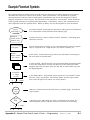
1
LD-V8000 Level II • NOTE TO USERS
LD-V8000 Level II Documentation
For Internal Program Control
Note to Users
This manual is based on the most up-to-date information for Level II program
development and delivery on the LD-V8000 available at the time of publication. It is
subject to change without notice. Although every reasonable effort has been made to
include accurate information, the statements in this document are not warranties.
Pioneer New Media Technologies, Inc., makes no warranty or claims as to the
accuracy, completeness or fitness for any particular purpose of the technical
information provided herein. Throughout this manual NOTES appear reflecting details
of the particular player functions which may be different on future players. The
NOTES are included to aid understanding, but should not be depended upon in
designing applications.
Please fill out the Registration Form on the next page and return it to us to insure
that you receive updated versions of the Level II Manual for the LD-V8000, and related
support materials as they become available. Also, comments, observations, and/or
corrections regarding this document would be appreciated.
For more information on Level I & III Program Control for the LD-V8000, please refer
to the LD-V8000 Level I & III User’s Manual /Programmer’s Reference Guide.
The Level I & III Manual for the LD-V8000 is available from Pioneer New Media
Technologies, Inc., Technical Support/System Integration, 310-952-2111
LD-V8000 Level II User’s Manual
TP 114
v. 1.1 • 8/92
A
LD-V8000 Level II • Table of Contents
LD-V8000 Level II DOCUMENTATION
for Internal Program Control
CONTENTS
Note to Users
User Registration Form
1. Introduction ..................................................................................1
- 1
1.1 Level II and the LD-V8000 ..............................................1
- 1
1.2 Chapter Highlights .............................................................1
- 2
2. Level II Basics ..............................................................................2
- 1
2.1 What is Level II ...................................................................2
- 1
2.2 Loading and Executing Level II Programs ..................2
2.2.1 Loading Level II Program Code into RAM ............2
2.2.2 Executing Level II Program Code from RAM ........2
2.2.3 Stopping Level II Program Execution ....................2
- 3
2.3 CAUTION:
Differences Between LD-V8000 & LD-V6000A ......2
- 3
- 4
- 4
- 5
2.4 Random Access Memory ..................................................2
2.4.1 Active Memory ...........................................................2
2.4.2 Program Area .............................................................2
2.4.3 Registers .....................................................................2
- 7
2.5 Program Format .................................................................2
2.5.1 Arguments ..................................................................2
2.5.2 Commands ......................................................2
2.5.3 Program Structure ............................................2
2.5.4 Execution Speed ..............................................2
- 14
Pioneer LD-V8000 Level II User’s Manual
TP114 v. 1.1
•
8/92
- 9
- 9
- 10
- 14
- 15
- 15
- 16
I
Table of Contents • LD-V8000 Level II
3. Entering Level II Program Code into RAM ................3
- 1
3.1 Entering Level II Code with the RCU .........................3
- 1
3.1.1
3.1.2
3.1.3
3.1.4
II
Entering Programming Mode ....................................3
Screen Display ............................................................3
Entering and Changing Program Code ..................3
Exiting Programming Mode .......................................3
- 1
3.2 Entering Level II Code via the RS-232 Port ..............3
3.2.1 Downloading Level II Codes ....................................3
3.2.2 Reading Level II Codes .............................................3
- 6
3.3 Level II Programs Encoded on Videodiscs .................3
- 10
3.4 Player Initialization ...........................................................3
- 12
4. Level II Commands for LD-V8000 ...................................4
- 1
4.1 Format Used to Describe Commands ............................4
4.1.1 Functions .....................................................................4
4.1.2 Tables ...........................................................................4
4.1.3 Explanations ...............................................................4
4.1.4 Notes .............................................................................4
4.1.5 Examples .....................................................................4
- 1
4.2 Level II Command Descriptions .....................................4
4.2.1 Program Load Control Commands ..........................4
1) PAGE (Set Page) ...................................................4
2) LOAD (Load Progeram From Disc) ...................4
3) MLOAD (Moving Load From Disc) .......................4
4) PLOAD (Partial Load From Disc) ........................4
5) MPLOAD (Moving Partial Load From Disc) ....4
- 4
4.2.2 Audio Control Commands .........................................4
6) AUDIO 1 (Audio 1 Output Control) .................4
7) AUDIO 2 (Audio 2 Output Control) .................4
8) AXX
(Set Audio Status) ....................................4
9) DAD
(Digital Audio Output Control) .............4
- 11
4.2.3 Video Control Commands .........................................4
10) VOFF (Video Off) ....................................................4
11) VON (Video On) ....................................................4
12) CGE (Character Generator Enable) .................4
13) CGD (Character Generator Disable) ................4
- 15
TP114 v. 1.1 • 2/92
- 2
- 3
- 6
- 6
- 9
- 1
- 2
- 2
- 2
- 3
- 4
- 4
- 5
- 6
- 8
- 9
- 11
- 11
- 13
- 14
- 16
- 16
- 17
- 17
Pioneer LD-V8000 Level II User’s Manual
LD-V8000 Level II • Table of Contents
`
4.2.3 Video Control Commands (cont.)
14) DISPLAY (Display Control) ................................4
15) SUD (Set User Display) ......................................4
16) CLD (Clear Display) ............................................4
17) BLINK (Blinking ON) ..............................................4
18) CLB
(Clear Blink) ...............................................4
19) SBC (Set Background Color) ............................4
4.2.4
20)
21)
22)
23)
24)
25)
26)
27)
28)
29)
30)
31)
32)
33)
34)
35)
36)
37)
- 17
- 19
- 19
- 20
- 20
- 21
Player Control Commands .......................................4
REJECT
...............................................................4
PLAY
...............................................................4
AUTOSTOP ...............................................................4
SEARCH ...............................................................4
WAIT
...............................................................4
PAUSE
...............................................................4
SLOW (Slow Speed) ................................................4
FAST (Fast Speed) ................................................4
MSF (Multi-Speed Forward).........................4
MSR (Multi-Speed Reverse)..........................4
STEP F
(Step Forward) ..............................4
STEP R
(Step Reverse) ...............................4
SFM (Set Frame Mode) .......................................4
STM (Set Time Mode) .........................................4
SCM (Set Chapter Mode) ....................................4
SSM (Set Still Mode) ...........................................4
TJF
(Track Jump Forward) ..............................4
TJR
(Track Jump Reverse) ...............................4
- 22
4.2.5 Program Execution Commands ................................4
38) BRANCH ...............................................................4
39) BRF (Branch on Failure) ...................................4
40) JUMP
...............................................................4
41) HALT
...............................................................4
42) NE
(No Entry) ....................................................4
- 33
4.2.6 Register Commands...................................................4
43) ADD
...............................................................4
44) SUBTRACT ...............................................................4
45) MULTIPLY ...............................................................4
46) DIVIDE
....................................................4
47) GET (Set Value into Register 0) .......................4
48) PUT (Transfer Value from Register 0) ............4
49) RECALL
(Recall Active Register) ....................4
- 36
Pioneer LD-V8000 Level II User’s Manual
TP114 v. 1.1
•
8/92
- 22
- 22
- 23
- 24
- 25
- 26
- 26
- 27
- 28
- 28
- 29
- 29
- 30
- 30
- 31
- 32
- 32
- 32
- 33
- 34
- 34
- 35
- 35
- 36
- 36
- 37
- 37
- 38
- 38
- 39
III
Table of Contents • LD-V8000 Level II
4.2.6 Register Commands (cont.)
50) ARG
(Argument) ..................................................4
51) COMPARE ...............................................................4
52) DECREG (Decrement Register) .........................4
53) DROP (Drop Low Order Digit) .............................4
54) RND
(Generate Random Number) ...................4
55) STORE (Store in Active Register) ..........................4
56) RRS
(Read Rear Switch) ....................................4
57) CLOCK (Clock Read and Reset).............................4
IV
- 40
- 41
- 42
- 43
- 43
- 44
- 46
- 47
4.2.7 Input Processing Commands....................................4
58) INPUT (Input from Digit Keys) ............................4
59) FIN
(Input with Function Keys) .....................4
60) TIN
(Input with Timeout) .................................4
61) FTI
(Input with Function and Timeout) .........4
62) DIN
(Digit Input).................................................4
63) BIN
(Binary Input) .............................................4
64) IIN
(Interrupt Input).........................................4
- 47
4.2.8 Flag Set
65) RCE
66) RCD
67) SCS
Commands...................................................4
(RCU Enable) ..............................................4
(RCU Disable) .............................................4
(Special Control Switches) .......................4
- 57
4.2.9 Transmit Commands .................................................4
68) TM
(Transmit Memory) ....................................4
69) ITM
(Increment & Transmit Memory)..........4
70) DTM
(Decrement & Transmit Memory).........4
71) STP
(Set Transmit Pointer) ..............................4
72) ITP
(Increment Transmit Pointer)..................4
73) DTP
(Decrement Transmit Pointer) ................4
- 59
4.2.10
74)
75)
76)
77)
Buffer Control Commands .........................4
(Set Video Memory Switches) ..................4
(Select Read Memory) ...............................4
(Memory Write Enable) .............................4
(Memory Write Disable) ............................4
- 61
4.3 LD-V8000 EPROM Upgrades ...........................................4
4.3.1 Video Delay Time ......................................................4
- 64
Video
SMS
SRM
MWE
MWD
TP114 v. 1.1
•
8/92
Pioneer LD-V8000 Level II User’s
- 48
- 50
- 51
- 52
- 54
- 55
- 56
- 57
- 57
- 58
- 59
- 59
- 59
- 59
- 60
- 60
- 61
- 62
- 62
- 63
- 64
LD-V8000 Level II • Table of Contents
Appendices:
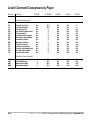
Appendix A: Comparison of Level II Commands
Available on Different Pioneer Players
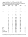
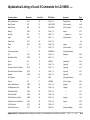
Appendix B: Alphabetical Listing of Level II Commands
Available on the LD-V8000
Appendix C: Hex Code Matrix of Level II Commands
Available on the LD-V8000
Appendix D: Character Generator: Table of Hex Codes
Appendix E: Numbers and Their Hex Code Equivalents
Appendix F: Sample Flow Charts and Level II
Program Examples — RCU entry
Appendix G: Sample Flow Charts and Level II
Program Examples — Programming
Accompanying Figures, by Chapter:
Chapter Two
Figure
Figure
Figure
Figure
Figure
Figure
Figure
2-A
2-B
2-C
2-D
2-E
2-F
2-G
Random Access Memory..............................................2
Active Memory Size and Memory Locations..................2
PAG Command, Memory Size and Register Numbers ...2
The Whole Program Area .............................................2
Program Area: One Page Active....................................2
Program Area: Two Pages Active ..................................2
Program Area: Seven Pages Active ...............................2
- 7
- 8
- 8
- 11
- 12
- 12
- 13
Chapter Three
Figure 3-A
Figure 3-B
Figure 3-C
Figure 3-D
Programming Mode On-Screen Display.........................3
RU-V6000T Remote Control Unit
Buttons Used for Level II Program Control ...............3
Structure of Pioneer Level II “Dump” ...........................3
Initialization ......................................................................3
- 2
- 3
- 11
- 12
Chapter Four
Figure 4-A
Figure 4-B
Digital and Analog Audio Switches ..............................4 - 11
Video Delay Time ........................................................4 - 64
Pioneer LD-V8000 Level II User’s Manual
TP114 v. 1.1
•
8/92
V
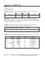
1. Introduction
1.1 Level II and the LD-V8000
1.2 Chapter Highlights
CHAPTER
1
LD-V8000
LEVEL II
USER’S MANUAL
Programmer’s Reference Guide
Pioneer LD-V8000 Level II User’s Manual
TP 114
v. 1.1
• 8/92
LD-V8000 Level II • Chapter One
1 Introduction
Before you use the LD-V8000, please read the safety information contained in the
Operating Instructions packaged with the player. For an overview of the three
player control methods: Level I, II and III, and for more details on player Operational
Basics, refer to the Pioneer LD-V8000 Level I & III User’s Manual / Programmer’s
Reference Guide, Technical Publication 113 Version. 2.0 3/91.
1.1 Level II and the LD-V8000
Although several earlier Pioneer Industrial Videodisc Players contained
programmable memory allowing for the execution of Level II programs, added
features of the Pioneer LD-V8000 now provide even more advanced Level II
capabilities. This LD-V8000 Level II User’s Manual/Programmer’s Reference
Guide provides information to assist programmers in the development of Level II
program applications for Pioneer’s model LD-V8000 industrial videodisc player.
The LD-V8000 is a highly flexible, programmable playback system that employs a
laser to read video and audio program material from a rotating videodisc. An
internal microprocessor controls all phases of the Pioneer LD-V8000’s operation,
processing external commands, internally-stored commands, and internally
generated control and status signals. The microprocessor makes possible the
player’s many “Play”, “Search”, and “Display” functions. The player includes 7K of
user-accessible Random Access Memory (RAM), allowing for the presentation of
significant player-controlled interactive videodisc applications.
Because the LD-V8000 is programmable, the exact sequence and display of
information presented to the viewer can be predetermined by an interactive
program designer and computer programmer. Audio-visual applications developed
for a wide variety of uses may be executed by the player’s internal microprocessor.
Properly constructed “stand-alone” Level II programs allow a wide range of
dynamic viewer interactions with the displayed material. This Level II program
may be loaded onto the player manually, downloaded from a computer, or read
from a Level II videodisc.
When a videodisc is manufactured with a properly formatted “Level II” program
encoded in the first few seconds of its Audio Channel 2, it is referred to as a Level
II disc. In addition to the normal Audio and Video, the Level II disc contains
computer readable instructions that define all, or part of, an interactive
application. Interactive programs stored within and executed by the LD-V8000 are
referred to as Level II programs, even if they do not require a Level II disc.
When a Level II videodisc is spun-up on the LD-V8000, its Level II program can be
automatically loaded into the player’s memory. When executed, the program will
tell the player what audio and video to present, and how to respond to user inputs.
Using a Remote Control Unit (RCU) or other input device, the viewer provides the
Pioneer LD-V8000 Level II User’s Manual
TP 114 v. 1.1
•
8/92
1-1
Chapter One • LD-V8000 Level II
player with the inputs used by the Level II program to guide its logical path. In
addition, the player can command external devices and can monitor some external
inputs. Typical interactive programs are written to shape the presentation of
audio-visual material to the user’s unique requirements — without the need for an
external computer to be attached to the videodisc player. Properly designed
programs for the LD-V8000 can bring outstanding performance, flexibility, and
interaction to applications developed for industry, business, education,
entertainment, and other uses.
This manual is intended to be a reference guide for programmers. It is not
intended to be an instructional course in Level II programming. It contains
explanations of concepts, terms, and Level II commands. If you are new to Level II
program development and/or plan to produce a Level II videodisc, we strongly
recommend working closely with an experienced Level II computer programmer,
Additional information may be obtained from Pioneer New Media Technologies,
Inc., West Coast Engineering Support, 310/952-2111 or East Coast Engineering
Support 201-327-6400.
1.2 Chapter Highlights
This manual is divided into chapters providing the following information:
Chapter One — Introduction
This chapter provides an overview of Level II videodiscs and the Pioneer LD-V8000
videodisc player. It also includes a summary of what information is included in
each chapter.
Chapter Two — Level II Basics
This chapter provides the basic concepts required for understanding Level II
programming and an overview of loading and executing Level II programs. This is
baseline information for new Level II application developers and is intended as a
reference for Level II application designers and programmers. This chapter contains
a CAUTION section which highlights the different hardware capabilities and Level II
commands available on the LD-V8000 as compared to the LD-V6000A. It also
provides an overview of the following essential subjects: Random Access Memory;
Addressable Program Areas and Registers; Program Formats; Arguments and
Commands; Level II Program Structure; and Command Execution Speed.
1-2
TP 114 v. 1.1
•
8/92
Pioneer LD-V8000 Level II User’s Manual
LD-V8000 Level II • Chapter One
Chapter Three — Using Level II
This chapter explains how to enter and execute short Level II demonstration and
test programs using either the remote control unit or an external computer. The
computer is attached to the player’s RS232C port. The chapter also provides
information about preparing Level II programming for encoding onto a videodisc.
Chapter Four — Level II Commands for LD-V8000
This chapter presents definitions and explanations of all LD-V8000 Level II
commands, both those previously available on the LD-V6000A and the new
commands that take advantage of the special capabilities of the LD-V8000.
Commands are presented by category: Program Load Control, Audio/Video Control,
Display Control, Player Control, Register Control, Input Processing, Program
Execution, Flag Set, Transmit, and Memory Control. Often, examples are included
for educational purposes, usually with comments explaining command usage.
The user will also find Notes referring to details which may be different on future
(or past) players. The information in the Notes is included to aid understanding
but should not be depended upon in designing applications.
Note: Most Level II program applications developed using the LD-V6000A command
set will run on the LD-V8000. However, some new hardware features and
accompanying Level II commands available on the LD-V8000 are not available on the
LD-V6000 or LD-V6000A.
See Appendix A for a chart comparing the Level II commands available on
different Pioneer programmable players: the LD-V8000, the LD-V6000A, the
LD-V6000, the LD-V3000, and the PR7820-3. For a complete alphabetical listing
of the Level II commands available for the LD-V8000, see Appendix B. Also, refer
to the LD-V8000 Level I & III User’s Manual/Programmer’s Reference Guide,
Appendix C: LD-V8000 Interface Cable Specifications, for the RS-232C port
specifications and some cable configurations useful in attaching various
computers.
Pioneer LD-V8000 Level II User’s Manual
TP 114 v. 1.1
•
8/92
1-3
2. Level II Basics
2.1 What is Level II?
2.2 Loading and Executing Level II Programs
2.2.1 Loading Level II Program Code into RAM
2.2.2 Executing Level II Program Code from RAM
2.2.3 Stopping Level II Program Execution
2.3 CAUTION: Differences between the
LD-V8000 & the LD-V6000A
2.4 Random Access Memory
2.4.1 Active Memory
2.4.2 Program Area
2.4.3 Registers
2.5 Program Format
2.5.1
2.5.2
2.5.3
2.5.4
Arguments
Commands
Program Structure
Execution Speed
CHAPTER
2
LD-V8000
LEVEL II
USER’S MANUAL
Programmer’s Reference Guide
Pioneer LD-V8000 Level II User’s Manual
TP 114
v. 1.1
•
8/92
LD-V8000 Level II • Chapter Two
2 Level II Basics
This chapter is intended to familiarize Pioneer LD-V8000 users with basic
concepts, terms, and procedures associated with developing and delivering Level II
program applications. A Level II program consists of a series of commands that,
when stored in the player’s RAM and interpreted by the microprocessor, cause the
player to operate in a pre-defined way.
This chapter explains how Level II programs can be written into the player’s
memory. It contains a CAUTION section detailing the differences between the
LD-V8000 and the LD-V6000A. It describes the player’s 7K Random Access
Memory — both the Program Area and the Registers. It also describes the
elements of a Level II Program: Arguments, Commands, variables , and data.
Finally, the chapter covers the structure of Level II Program code in memory and
instruction Execution Speed.
2.1 What is Level II?
As with the authoring languages used for other interactive video productions, the
Level II programming language is responsive to new hardware capabilities. Thus, it
continues to evolve. Sophistication of Level II applications depends upon the
increasing knowledge of programmers and developers who work with the system.
Any successful interactive videodisc production requires meticulous planning and
Level II applications are no exception to the rule. A well-planned, carefully
programmed Level II application can provide a very complex and highly interactive
application that is extremely easy to work with — requiring no prior computer
knowledge on the part of the viewer. The Level II system allows both simple and
complex interactive programming to be delivered with only a Level II videodisc
player, a remote keypad, a monitor, and, of course, a videodisc. It does not require
an external computer to send commands to the player.
In most cases, a Level II program is prepared and tested in advance of disc
production. The program's object code is encoded into Audio Channel 2 when the
videodisc is manufactured. When the start-up parameters on the LD-V8000 are
set for automatic Level II execution, the disc's Level II program is loaded into the
player’s memory just after the disc spins up. However, Level II discs are not
required. For some applications, the "Level II" program is simply entered into the
player’s memory with the RCU or downloaded into the videodisc player’s memory
from a computer.
For trade shows, museums, and other situations where the program and the
videodisc do not change, the program might simply reside in the player. However,
when there is a library of training videodiscs to choose from, it is quite convenient
to select the one disc (lesson) you want, put it into the player, and have the whole
lesson ready to run. No floppy disks or complex startup procedure. Likewise,
when a network of point of purchase kiosks must be updated monthly, it is again
most convenient to simply mail out a new videodisc for the store manager to put
Pioneer LD-V8000 Level II User’s Manual
TP 114 v. 1.1
•
8/92
2-1
Chapter Two • LD-V8000 Level II
into the player. The simplicity and overall low cost of updating the entire
interactive network in this manner is noteworthy.
Level II applications have saved developers and system integrators thousands of
dollars in hardware costs by allowing applications to be used in multiple settings
without an expensive computer at every workstation. Level II applications provide,
in effect, “stand-alone systems”. When Level II programs are carefully planned and
efficiently developed, companies find that cost savings using Level II program
delivery are substantial, primarily because a computer is not required to control
each videodisc player kiosk or station. Level II delivery systems are often
comprised entirely of “off the shelf” components. This can lower the cost, allow for
faster system delivery and simplify set-up for customers.
When a Level II encoded videodisc spins-up on the LD-8000, program code on
Audio Channel 2 of the disc can be automatically loaded or “dumped” into the
LD-V8000’s 7K of RAM. The program information is written into one of seven
“pages”, where each page can contain 1022 bytes of information.
Earlier Pioneer Industrial Videodisc Players (the LD-V6000 series, the LD-V3000,
and the PR-V7820-3) are also capable of loading and executing Level II programs.
However, they all have slightly different hardware capabilities. Thus, the available
Level II commands also vary from player to player to reflect these differences.
(See Section 2.4, CAUTION: Differences Between the LD-V8000 and the
LD-V6000A. See also Appendix A, Comparison of Level II Commands
Available on Different Pioneer Industrial Laserdisc Players.)
The succession of players has been generally upward compatible. Usually discs for
the PR-V7820-3 run on the LD-V6000, LD-V6000A, and on the LD-V8000. In
order to take advantage of the latest hardware features, we urge developers to
write Level II programs for use with specific players. Note that other players in the
current Pioneer Industrial Videodisc product line: the LD-V2000, LD-V2200,
CLD-V2400, LD-V4400, and the LC-V330 (Autochanger), are not “Level II” players
and do not contain an internal microprocessor that will execute Level II programs.
When new LD-V8000 players are purchased, Level II programs written for and
tested on LD-V8000 players containing older EPROMs (Erasable Programmable
Read Only Memory chips) should be thoroughly tested with the newer EPROMs
that may contain improvements and additional features. (See Technical Bulletin
#131, LD-V8000 Version Upgrade.)
All Level II programs should be thoroughly tested, preferably with a proof disc,
before the master stamper is made and replicates are pressed. A proof disc is a
pre-replication test disc containing all program video, audio, and Level II program
information. It is used to verify and confirm both the video and audio material
and the disc’s interactive programming functions.
2-2
TP 114 v. 1.1
•
8/92
Pioneer LD-V8000 Level II User’s Manual
LD-V8000 Level II • Chapter Two
Caution: Pioneer Level II programs will not execute on "Level II players" produced
by other manufacturers, because Level II languages vary between manufacturers.
Level II programming code is usually developed and tested using an external
computer to edit, compile, download, and test the application. Then, a properly
formatted object code version of the program is submitted to a specific videodisc
manufacturer for encoding into Audio Channel 2 of the videodisc. Although
hundreds of dumps can be placed on a single disc, typically, from one to fifteen
program dumps (1022 bytes each) are encoded onto a Pioneer videodisc.
2.2 Loading and Executing Level II Programs
The LD-V8000’s microprocessor, in addition to directly controlling the videodisc
player’s operations, provides the user with seven pages and one extra register
(7156 bytes) of RAM. This memory space is available for the storage of userdesigned Level II program instructions, associated data, and variables. Level II
program instructions stored in RAM are executed by an interpreter program that
is resident in the player’s EPROMs.
2.2.1 Loading Level II Program Code into RAM
Programming code may be entered directly into the player’s memory to allow
execution of stand alone programs that do not require a Level II disc. More
commonly, however, interactive Level II programs are generated on a computer,
downloaded to the player for testing, and then sent to videodisc manufacturing to be
encoded onto a videodisc. Then, the On-Screen Function Switch Settings of the
LD-V8000 can be set to automatically load a Level II program from a videodisc into
the player’s memory. The program read from disc is executed to control the player.
Thus, Level II programs are loaded into RAM from three different sources:
• Automatically from Disc, by reading programs encoded on Audio
Channel 2 of a Level II videodisc (Program Dumps).
• Manually with the RCU, entering program argument, command, and
data codes individually, using the RU-V6000T remote control unit.
• Via the RS-232C port from an External Computer, downloading
each page of codes in just a few seconds.
To prepare the LD-V8000 to automatically load a Level II program from a Level II
videodisc, make sure that the player's Level II Auto Start parameter is set to Load
From Disc, as described below:
• Power-On the player while simultaneously pressing the player's DISPLAY
button. This allows customization of any of the player’s On-Screen
Function Switch settings.
Pioneer LD-V8000 Level II User’s Manual
TP 114 v. 1.1
•
8/92
2-3
Chapter Two • LD-V8000 Level II
• Press the SCAN FORWARD button four times to select Page 4 of the
On-Screen Function Switch Setting menus.
• Press the STEP FORWARD button to select Level II Auto Start.
• Press the STEP REVERSE button to choose the option, Load from Disc.
• Press the DISPLAY button to store the chosen options.
For more about the available options, see the LD-V8000 Level I & III User’s
Manual/Programmer’s Reference Guide: On-Screen Function Switches and
On-Screen Status Displays in Manual Mode, Audio Status Display.
Then, make sure that Audio Channel 2 is ON as the disc spins up. In general it is not
necessary for Audio 2 to be ON for the player to read dumps, but Audio 2 OFF during
spinup tells the player to skip its initial dump load detection sequence.
For more information about loading Level II programming codes to the player’s RAM
using the RCU, see Section 3.1. For information about sending Level II code to the
player’s RAM from a computer via the RS-232C port, see Section 3.2.
2.2.2 Executing Level II Program Code from RAM
Level II programs loaded from videodisc automatically begin execution when they are
loaded. However, one may wish to automatically execute a program that is already in
the player’s memory independent of the type of disc or the original source of the
program. In this case, set Level II Auto Start, as described above, but choose the
Back-Up Memory option. This will cause the player to automatically begin execution
of the code stored in memory, as soon as any videodisc is spun up. CAUTION: When
running programs automatically with the Back-Up Memory setting, make sure
that the program code begins at program address 0.
The Level II program remains in the player’s RAM indefinitely, until it is overwritten.
The LD-V8000 contains a lithium battery so that a Level II program can be held in
memory up to 5 years, even when the player is not plugged in.
To begin execution of a program manually, press the RUN button on the RCU.
To use an external computer to command execution to begin, send a "RUN" (*R)
command.
2.2.3 Stopping Level II Program Execution
To stop execution of a Level II program, press the CLEAR/HALT button on the remote
control unit, or send a “HALT” command (*H) from an external computer. When the
program is “halted”, the player changes from Automatic Mode to Manual Mode.
NOTE: If the HALT is sent during the execution of an AUTO STOP command, the
player will continue execution of the AUTO STOP even though it is in Manual Mode.
2-4
TP 114 v. 1.1
•
8/92
Pioneer LD-V8000 Level II User’s Manual
LD-V8000 Level II • Chapter Two
2.3 Caution: Differences Between the LD-V8000 and the LD-V6000A
Level II developers must be aware of both hardware and Level II language command
differences between the LD-V8000 and the LD-V6000A. It is advised that any Level II
program be prepared, tested, and then used with specific players. Programs can be
carefully written to work “properly” on several player types. Programs using the new
LD-V8000 features may not execute “properly” on other players.
Although sales of the LD-V6000A were discontinued in March 1991, Pioneer New
Media Technologies, Inc., Engineering Support continues to provide technical
support for that player, as well as for other discontinued Pioneer Industrial
Videodisc players.
The LD-V8000 has new features and increased capabilities that make it a more
advanced player than the LD-V6000A. New features of the LD-V8000 can be
accessed with new or modified Level II commands. Some of the new player
features are:
• Four Channels of Audio: The player can simultaneously read and
process two channels of Analog Audio and two channels of Digital
Audio. Thus, program designers have access to four independent
audio tracts. For example, these could be used as four different
interpretations or languages, all relating to the same video material.
• Video Buffer. The player's ability to capture and hold any frame of
video on the disc provides “seamless” searches, CLV “still-frames”,
and “Sound-Over-Still”. With new Level II commands to control this
buffer, special user-programmed effects are possible.
• CLV Frame Access. Most Level II commands now apply to CLV
videodiscs, facilitating highly interactive CLV applications.
• Rapid Search Time. The player provides one-half second access across
an entire CAV disc. Three seconds access across an entire CLV disc.
In the past, Level II applications were prepared only for CAV discs because CLV discs
did not allow the full range of interactive capabilities (Still Frame, Step Forward and
Reverse, Multi-Speed Forward and Reverse, etc.) The LD-V8000’s video memory
buffer makes possible “CLV interactive”, with “frame accurate” CLV searches. Thus,
it is now possible to create significant Level II applications for CLV discs.
Special care must be taken when programming Level II applications for CLV discs.
CLV “frame access” uses up to seven-digit arguments: for example, 1231514 to
represent 1 hour, 23 minutes, 15 seconds, and frame number 14 (of frame 0 to 29
within the second). Usually 6 digits are sufficient, but Level II registers contain a
maximum value of 65535 and cannot hold six-digit values for arguments.
Pioneer LD-V8000 Level II User’s Manual
TP 114 v. 1.1
•
8/92
2-5
Chapter Two • LD-V8000 Level II
Four new Video Buffer control commands have been added to the LD-V8000
command set. For detailed explanations see Section 4.2.10. They are:
• Set (Video) Memory Switch:: Allows user control over the Video Buffer,
inhibiting the normal automatic use of the Video Buffer by the player.
A Field Mode or Frame Mode may be selected for the buffer.
• Select Read Memory: For Field Mode, this command selects the video buffer
field (0 or 1) to be used for generating the player's video output signal.
• Memory Write Enable: Allows disc-generated video signals to be written into
the video buffer. In Field Mode, the command selects which video buffer
field (0 or 1) will be written.
• Memory Write Disable: Disables writing into the video buffer.
Both the LD-V8000 and the LD-V6000 provide Binary Output, but the LD-V8000
does not support the 6000’s Ascii-Hex Output mode. The Binary Output is most
useful in controlling external serial devices via the RS-232C port, for example, a serial
printer used to provide feedback to viewers via a scorecard or coupon print-out.
Note: The Level II Transmit Register commands available on earlier player models
have been eliminated, along with a number of the Transmit Status commands.
Since RF Output and Antenna Input are not available on the LD-V8000, the Antenna
Input Enable and Disable commands have been eliminated. Since CX control is
automatic, the CX Enable and CX Disable commands have also been eliminated.
(Refer to Appendix A, Comparison Chart of Level II Commands available on
various Pioneer Videodisc Players.)
The LD-V8000 offers the best of the LD-V6000A — its programmable memory and
command set for Level II programming, along with the best of the LD-V4200 — its
standard mnemonic command set for Level III computer control of the player.
The LD-V8000 may receive viewer input during Level II program execution from
either RCU, the RU-V6000T or the RU-V103. With the RU-V6000T, one can do
manual Level II programming. See Section 3.1 Sending Level II Code to the LDV8000 with the RCU. Also see Appendix F, Flow Chart and Sample Level II
Code.
Note: Since the RU-V103 remote control unit lacks the "Program" button, it cannot
be used to write Level II code into the player’s RAM.
2-6
TP 114 v. 1.1
•
8/92
Pioneer LD-V8000 Level II User’s Manual
LD-V8000 Level II • Chapter Two
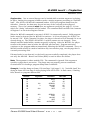
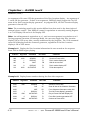
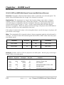
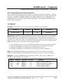
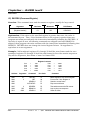
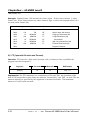
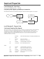
2.4 Random Access Memory
The LD-V8000 includes a 8086 microprocessor, two EPROMs that contain the basic
operating system of the player, and seven kilobytes of Random Access Memory
(RAM), of which 7156 bytes are available for Level II programming. The RAM holds
program codes, the registers, and other data. This coexistence requires RAM to be
addressed in two ways. One addressing method is used to store single-bytes of
program code and data. The second method is used to manipulate the values stored
in two-byte registers.
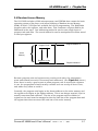
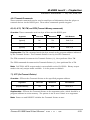
Active
Memory
{
Program Address 0
Program Code
Registers in Use
Register Number 0
Figure 2-A
Because program code and registers may overlay each other, the programmer
must understand how each is structured and addressed. (See Figure 2-A, above.)
Since there is rarely a good reason to allow program code to overlap the registers
in use, the programmer should usually consider such an overlap to be an error,
and make every effort to avoid it.
Generally, the program code begins at the lowest address in the active memory and
the register area begins at the highest address. This is not always required, but it is
usually convenient and sufficient. The size of the program and the number of
registers to be used must be managed so that the total size of the program data and
the register data does not exceed the total size of the active memory.
Pioneer LD-V8000 Level II User’s Manual
TP 114 v. 1.1
•
8/92
2-7
Chapter Two • LD-V8000 Level II
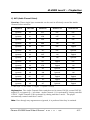
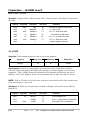
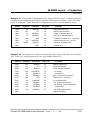
Active Memory Size
Pages
Memory Locations
Bytes
Range
Hi Byte Reg N
Low Byte Reg N
1
1024
0-1023
1022 - 2*N
1023 - 2*N
2
2046
0-2045
2044 - 2*N
2045 - 2*N
3
3068
0-3067
3066 - 2*N
4067 - 2*N
4
4090
0-4089
4088 - 2*N
4089 - 2*N
5
5112
0-5111
5110 - 2*N
5111 - 2*N
6
6134
0-6133
6132 - 2*N
6133 - 2*N
7
7156
0-7155
7154 - 2*N
7155 - 2*N
Figure 2-B
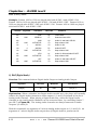
“PAGE”
Command
Active
Memory Size
Register Numbers
Pages
Bytes
Range
Reg # at Location M
0 PAGE
1
1024
0-511
INT ((1023-M)/2)
1 PAGE
2
2046
0-1022
INT ((2045-M)/2)
2 PAGE
3
3068
0-1533
INT ((3067-M)/2)
3 PAGE
4
4090
0-2044
INT ((4089-M)/2)
4 PAGE
5
5112
0-2555
INT ((5111-M)/2)
5 PAGE
6
6134
0-3066
INT ((6133-M)/2)
6 PAGE
7
7156
0-3577
INT ((7155-M)/2)
Figure 2-C
2-8
TP 114 v. 1.1
•
8/92
Pioneer LD-V8000 Level II User’s Manual
LD-V8000 Level II • Chapter Two
2.4.1 Active Memory
The player’s RAM is divided into seven 1022-byte blocks called Pages, and one
2-byte block called Register 0. Each RAM memory location is one eight-bit byte.
Memory locations begin at Address 0 and continue to Address 7155. Depending
upon the argument of the most recent Page (PAG) command, the active memory
may consist of one to seven pages, and Register 0. This gives an Active Memory
Size of 1024, 2046, ..., 7156 bytes. Register 0 is not changed by any program
load from disc and it occupies two fixed bytes of memory that are separate from all
of the pages. However, the two bytes of Register 0 can usually be addressed as the
last two program locations of Active Memory.
2.4.2 Program Area
The program area is a part or all of the player’s Active Memory. Program
instructions (arguments and commands) are written into the program area, along
with other data (characters, etc.). A program is usually loaded from a videodisc in
units of one page, or, in unusual circumstances, as a partial page.
The size of the active program area can be set by the Page command, allowing
from 1 to 7 pages to be active. The actual size of the active program, including
Register 0, can be calculated as follows:
Number of active pages x 1022 + 2 bytes
At power-on, there is only one page active (1022 bytes plus Register 0). This
provides for compatibility with earlier players and program dumps which do not
use the Page command. Beginners will often write program dumps for the
LD-V8000 in one of two ways:
• Without using the PAG command, for small programs or when
compatibility with the oldest players is desired.
• Using the “6 PAG” command to make the active memory as
large as possible.
Program instructions, (arguments and commands) are stored in coded format.
Each digit of an argument and each command is a one-byte code which occupies
one memory location. For example, the instruction, 1536 Search, consists of a
4-byte argument and the one-byte SC command, represented in memory by the
following five bytes of Hex code: 0F, AF, 4F, 6F, and F7.
See Chapter 4, Level II Commands the LD-V8000 for an explanation of specific
program commands and Appendix B, Alphabetical Listing of Level II
Commands Available on the LD-V8000. Both Chapter 4 and Appendix B
include the commands’ corresponding one-byte Hex codes.
Pioneer LD-V8000 Level II User’s Manual
TP 114 v. 1.1
•
8/92
2-9
Chapter Two • LD-V8000 Level II
2.4.3 Registers
All or part of any page in active memory can be used to hold register data. Each
register occupies two bytes (two memory locations). The most significant byte of a
register is at an even program address, the least significant byte is at the next
higher location (odd address). There are 511 registers in each active page.
Register storage begins at the highest program address and proceeds downward:
When only one page is active, Register 0 occupies program addresses 1022 and
1023, while Register 511 occupies program addresses 0 and 1. Since this
correspondence of register number to program addresses changes with the use of
the Page command, the two program addresses corresponding to a particular
register number can be computed with the aid of Figure 2-B of this chapter.
Registers store data in a 16-bit binary unsigned integer format. For example, the
value 1536 can be stored in a register as the hexadecimal value ‘0600’. Since a
register is 16 bits long, it can contain a value of 0 through 65535. There are no
negative numbers, and larger numbers are usually taken modulo 65536.
The Active Register Pointer holds a number designating which register is currently
considered to be “Active”. Of the available registers, one will always be designated
as the current “Active Register”. Register 0 is designated as “active” at power-on.
Any register in RAM can be designated as active by specifying it as the argument of
a Recall command. In addition, the Active Register Pointer is increased by one
whenever one of the following commands are executed: Autostop, Search, Store,
and Recall. These commands may use the contents of the current active register.
Then, they always activate the next highest register.
The following charts show the relationship between active memory size, program
addresses, register numbers, and memory addresses in the active program area.
These “Memory Addresses” are the addresses used when reading or writing Level II
program code through the RS-232C port.
Note: The relationship between program addresses and register numbers changes if
the size of the active memory (number of active pages) is changed. Reading or
writing program codes through the RS232C port always uses the memory addresses,
and all of the pages can be accessed, independent of the size of active memory.
2-10
TP 114 v. 1.1
•
8/92
Pioneer LD-V8000 Level II User’s Manual
LD-V8000 Level II • Chapter Two
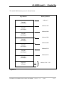
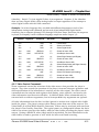
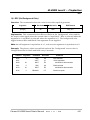
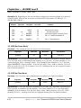
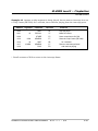
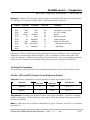
The whole RAM memory area is shown below.
Page Number
Memory Address
Address 0
Page #0
(1022 bytes)
Address 1022
Page #1
(1022 bytes)
Address 2044
Page #2
(1022 bytes)
Address 3066
Page #3
(1022 bytes)
Address 4088
Page #4
(1022 bytes)
Address 5110
Page #5
(1022 bytes)
Address 6132
Page #6
(1022 bytes)
Register 0
(2 bytes)
7154
7155
}
Address 7154 - 7155
Figure 2-D
Pioneer LD-V8000 Level II User’s Manual
TP 114 v. 1.1
•
8/92
2-11
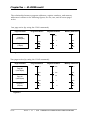
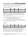
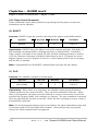
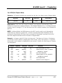
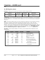
Chapter Two • LD-V8000 Level II
The relationship between program addresses, register numbers, and memory
addresses is shown in the following figures, for one, two, and all seven pages
active.
One page active (by using the 0 PAG command):
Page Allocation
Program Address
Register Numbers
Memory Addresses
0
R 511
0
Page #0
(1022 Bytes)
R
1021
Register 0
(2 Bytes)
1021
1
7154
1022
R
1023
0
7155
Figure 2-E
Two pages active (by using the 1 PAG command):
Page Allocation
Program Address
0
Register Numbers
Memory Addresses
0
R 1022
Page #0
(1022 Bytes)
Page #1
(1022 Bytes)
1021
R
512
1021
1022
R
511
1022
2043
R
1
2043
¯
Register 0
(2 Bytes)
2044
2045
R
0
7154
7155
Figure 2-F
2-12
TP 114 v. 1.1
•
8/92
Pioneer LD-V8000 Level II User’s Manual
LD-V8000 Level II • Chapter Two
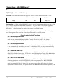
Seven pages active (by using the 6 PAG command):
Page Allocation
Program Address
Register Numbers
Memory Addresses
0
R 3577
0
1021
R 3067
1021
1022
R 3066
1022
2043
R 2556
2043
2044
R 2555
2044
3065
R 2045
3065
3066
R 2044
3066
4087
R 1534
4087
4088
R 1533
4088
5109
R 1023
5109
5110
R 1022
5110
6131
R
512
6131
6132
R
511
6132
7153
R
1
7153
Page #0
(1022 Bytes)
Page #1
(1022 Bytes)
Page #2
(1022 Bytes)
Page #3
(1022 Bytes)
Page #4
(1022 Bytes)
Page #5
(1022 Bytes)
Page #6
(1022 Bytes)
Register 0
(2 Bytes)
7154
7155
7154
R
7155
0
Figure 2-G
Pioneer LD-V8000 Level II User’s Manual
TP 114 v. 1.1
•
8/92
2-13
Chapter Two • LD-V8000 Level II
2.5 Program Format
The following is a brief description of the two parts of a Level II instruction used to
control the LD-V8000 videodisc player — the arguments and the command. Also
included is an overview of Level II program code structure and of command
execution speed. Specific Level II commands and arguments are described in
Chapter 4, Level II Commands for the LD-V8000.
2.5.1 Arguments
An argument is attached to a command to provide a numeric parameter useful for
the command's execution. Arguments represent integer data, CAV or CLV frame
numbers, time codes, chapter numbers, program addresses, register numbers,
time delays, or other values. In Level II Programs, the argument, if any, is always
placed before the command.
Any number of digits can be placed before the command to form the argument.
However, only the lower-order seven digits are used for a CLV frame number, the
lower two digits for a chapter number, and the lower five digits for most other
parameters.
In addition to the ten digits (0 - 9), several other program codes (ARG, DIN, DRP,
etc.) are also considered to be argument codes, because they generate argument
digits for the command that immediately follows them. For example, 123 ARG DRP
ARG 12 ARG is a nine-code argument that creates argument digits for a following
command (such as “Search”).
NOTE: Usually, the arguments generated in this manner are five digits (they can be
more) and they may be taken modulo 65536. Usually extra high-order digits are
ignored. But Beware, the instruction 90000 DRP SC does not search to frame 9000
but the instructions 12345 GET 0 ARG DRP 7 SC may indeed find frame 23457.
Some commands don’t require arguments; others do, often because the default
argument (usually zero) does not make sense. When the argument is optional,
there is usually a meaningful default or an implied argument can be taken from
the active register. Unless otherwise specified, no argument is equivalent to a zero
argument.
Each numeric digit of an argument is internally represented as a one-byte code.
Thus, each digit (or other argument code) occupies one memory location.
Note: Registers can only hold the values 0 through 65535.
2-14
TP 114 v. 1.1
•
8/92
Pioneer LD-V8000 Level II User’s Manual
LD-V8000 Level II • Chapter Two
2.5.2 Commands
The Level II command set represents the functions available for development of a
Level II program. Many of the commands are direct counterparts of buttons on the
RCU (e.g., SEARCH, AUDIO1, DISPLAY, etc.) and they cause corresponding
operations to be performed by the player. Other commands are used for
controlling program interpretation, directing the path of execution, managing
registers, etc. A command is stored as a one-byte code in the active memory.
Any argument must be placed before the command. An argument, if any, and the
following command make an instruction. See Chapter 4, Level II Commands for
the LD-V8000, for a description of each Level II command. Refer also to Appendix
B, Alphabetical Listing of Level II Commands Available on the LD-V8000.
Many commands can be executed directly by the player or entered into RAM from
the RCU with a single button press. All codes and any data byte can be entered
into RAM as a hexadecimal code, with three button presses on the RCU. See the
procedure described in Section 3.1.3, Entering Level II Code with the RCU.
When the programmer enters arguments, commands, and data from the RCU, the
video display shows the byte codes on-screen as command or digit mnemonics
whenever possible. Unrecognized codes are displayed as two-character hex values.
2.5.3 Program Structure
A Level II program segment, when stored in memory, is a continuous string of onebyte codes. The string is processed by the player's Level II program interpreter
beginning at the location specified or implied by the RUN command. As each byte
is examined, argument codes are accumulated until an executable command code
is found. Some commands have explicit arguments, others have implied
arguments, default arguments, or no arguments.
As an example, the two instructions 1000 SC 2000 AS are internally represented
as codes 0F, 3F, 3F, 3F, F7, 8F, 3F, 3F, 3F, F3. Starting with the first byte, 0F, the
argument is accumulated while the codes are scanned for a command code. In
this example, the Search command code, F7, is detected. The SC command, using
the currently accumulated argument (0F, 3F, 3F, 3F), instructs the player to
position the laser read head at frame 1000.
When the player is executing Level II program code (in Automatic Mode), succeeding
commands from memory are not processed until the function specified by the
“current” command has been completed. The Play command and the INN command
are the exceptions. A Play command instructs the videodisc player to begin playing
audio-video material and continue until instructed to do something else by another
command.
Pioneer LD-V8000 Level II User’s Manual
TP 114 v. 1.1
•
8/92
2-15
3. Entering Level II Code into RAM
3.1 Entering Level II Code with the RCU
3.1.1
3.1.2
3.1.3
3.1.4
Entering Programming Mode
Screen Display
Entering and Changing Program Code
Exiting Programming Mode
3.2 Entering Level II Code via the RS-232 Port
3.2.1
3.2.2
Downloading Level II Codes
Reading Level II Codes
3.3 Level II Programs Encoded on Videodiscs
3.4 Player Initialization
CHAPTER
3
LD-V8000
LEVEL II
USER’S MANUAL
Programmer’s Reference Guide
Pioneer LD-V8000 Level II User’s Manual
TP 114
v. 1.1
•
8/92
LD-V8000 Level II • Chapter Three
3 Entering Level II Code into RAM
Either the RCU or an external computer attached to the player’s RS-232C port
may be used to enter simple or complex Level II programs into the player’s
memory. Complete Level II applications (usually short) are sometimes entered
with the RCU and retained in the LD-V8000’s memory by it’s 5-year battery.
However, the RCU is most often used for interactive input, examining variables, or
patching and examining code during the testing of larger programs. These are
usually written and edited on an external computer, compiled with a Level II
computer utility, and downloaded into the player for thorough testing. This
procedure is highly reliable and is strongly recommended. Section 3.1 and
Section 3.2 of this chapter explain both ways of entering Level II codes into the
player’s memory.
Sometimes, a Level II simulator utility program is used for testing, instead of
downloading code into a player. Since the best simulator may not exactly
duplicate a particular model of videodisc player, it is best to test applications on
the player actually intended for use, including a final check using a proof disc. No
application should be considered ready for mass production until a proof disc has
been extensively tested and approved.
Section 3.3 of this chapter describes how Level II programs are encoded in the
Audio Channel 2 of a Pioneer videodisc.
Caution: This manual is intended to be a reference guide, not an instructional
manual in the fundamentals of computer programming. Actual programming
procedures and methods are not explained anywhere in this manual. If you decide
to create your own Level II videodisc application and you are not familiar with
computer programming, we strongly suggest you become familiar with
programming concepts. This will help you to make best use of the considerable
power of the Level II videodisc programming language. In any case, it is highly
recommended that you contract an experienced Level II programmer before you
begin the project. Pioneer New Media Technologies, Inc., Engineering Support,
can answer questions or refer you.
3.1 Entering Level II Code with the RCU
Here are the steps for entering Programming Mode and entering Level II
codes into the LD-V8000 using the RU-V6000T remote control unit (RCU):
3.1.1 Entering Programming Mode
Pressing the PROGRAM button on the RCU when the player is ON, or when it is in
Manual Mode (i.e. when a disc has been spun-up, played and stopped) puts the
player into Programming Mode, ready to receive Level II program code input. You will
see an on-screen program address indicator appear on the video monitor attached to
the LD-V8000. If no argument is specified before the PROGRAM button is pressed,
Pioneer LD-V8000 Level II User’s Manual
TP 114 v. 1.1
•
8/92
3-1
Chapter Three • LD-V8000 Level II
programming will begin at address 0. If an argument is used, programming will
begin at the specified program address.
3.1.2 Screen Display
When the player is in Programming Mode, the monitor displays a four digit
(decimal) program address at the upper left of the screen. Mnemonics
representing one or more sequential program codes are displayed on a second line.
The displayed program address is the address of the rightmost byte of code
(command, argument digit, or data) displayed on the second line.
PRG. = 0011
PRG. = 0011
1DI ,1000SC ,1200AS
Program Address
1 DI ,1 0 0 0 SC ,1 2 0 0 AS
As code is entered, the
display line shifts left.
This Program Code is at the
program address shown.
The code then shifts left.
Figure 3-A
Notice: Each argument digit or command takes up one byte.
The rightmost code byte is special, it's value may be replaced by a code entry from
the RCU. When a new code replaces an old code, the display shifts to the right so
that the next code byte in active memory is displayed as the rightmost mnemonic.
While in Programming Mode, the PROGRAM button does not enter a replacement
code, it preserves the codes displayed and just shifts the second line left to display
the next program code. By pressing the PROGRAM button repeatedly, entire
program segments can be reviewed and verified.
The displayed mnemonics differ depending upon the contents of each byte. Each
argument digit code is displayed as a one-digit numeric character. Other codes are
displayed in a three-character area followed by a comma. Most commands are
displayed as a 1, 2, or 3-character mnemonic. Other program codes are displayed as
a hexadecimal value preceded by an asterisk (i.e. *BA). A code value being entered
using the “Hex Code Entry” method starts to appear on screen in Hex, but the code's
mnemonic, if any, is used in the display as the code byte shifts left.
For example, the Set Frame Mode command has no single corresponding RCU
button. Appendix B, Alphabetical List of Level II Commands indicates that the
Hex code is 8E and the mnemonic is SFM. As the first Hex digit (the “8”) is entered,
one can see an “*8” on the screen. However, as the second Hex digit (the “E”) is
pressed, the display will shift to the left showing the SFM command mnemonic and
the displayed program address will be incremented by one.
3-2
TP 114 v. 1.1
•
8/92
Pioneer LD-V8000 Level II User’s Manual
LD-V8000 Level II • Chapter Three
3.1.3 Entering and Changing Program Code
When the RU-V6000 RCU is used to enter program codes, bytes of code in memory
are changed one byte at a time. The program address displayed on the screen
indicates the memory location of the code byte that will be changed by an entry. The
entry is a simple one-for-one replacement - a code cannot be inserted between other
codes in memory. If an erroneous code is discovered, a correct code can be rewritten
over the offending code. However, if a code is omitted, a whole section of codes may
have to be re-entered.
As codes are entered into RAM with the RCU, the program address is incremented by
one each time a byte of code is entered. During entry, press the PROGRAM button
instead of entering a code value to “skip over” a byte of code without replacing it.
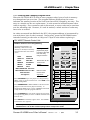
RU-V6000T Remote Control Unit
•
Buttons used for Level II Programming
In Programming Mode, the
following codes can be sent
directly to the Player’s memory
from the RCU with one button
press:
STOP
DISPLAY
AUDIO 1/L
AUDIO 2/R
INPUT
DEC REG
SEARCH
AUTOSTOP
RECALL
STORE
BRANCH
HALT
MULTI-SPEED SET Slow Fast
MULTI-SPEED PLAY Fwd. Rev.
STEP Fwd. Rev.
The Digits 0-9
REJECT
PLAY
Pressing PLAY
prepares the player
to receive a two-digit
Hex Code entry,
using 0-9 and A-F.
MULTI-SPEED SET
SLOW
SEARCH
D
Press PROGRAM to put the player into Programming
Mode, ready to receive Level II code. Press END to exit
Programming Mode.
Press RECALL to examine register data. Use STORE
to load data into registers.
DEC REG
E
AUDIO 1/L
F
STEP
AUDIO 2/R
A
B
C
7
8
9
RECALL
4
5
6
CLR/HALT
1
2
3
STORE
0
PROGRAM
END
RUN/BRCH
Press RUN/BRANCH in Manual Mode to execute Level II
program code stored in the player’s memory. in
Programming Mode use it to enter a BRANCH command
to loop back to a specific program address.
Press CLEAR/HALT to stop Level II program execution.
In Programming Mode, it enters a HALT command into
Level II code.
DISP
MULTI-SPEED
AUTO STOP
Buttons 0-9 are
used for most
arguments.
FAST
SCAN
INPUT
Buttons A-F can be
used for Hex
Entries.
STOP
FRAME/CHAP.
LaserDisc
VIDEO DISC PLAYER
REMOTE CONTROL UNIT RU-V6000
?
?
?
?O2@@@f?@@6K?
?
?W2@@@@@f?@@@@6K?
?
O&@@@@@@f?@@@@@@6X?
?
W2@@@@@@@@f?@@@@@@@)X
?
7@@@@@@@@@f?@@@@@@@@)X?
?
?J@@@@@(Y@@@f?@@@@@@@@@1?
?
W&@@@@(Y?@@@f?@@@V'@@@@@Lhe@@@@@@@@@@@@@@@@@@@@@@@6X??@@@@@@@@@fO2@@@@@@@@@@@@@@@@6Ke?@@@@@@@@@@6X?h@@@@@?eW2@@@@@@@@@@@@@@@@@@@@@(eO2@@@@@@@@@@@@@@@@@@@@(?@@@@@@@@@@@@@@@@@@@@@@@6K?e@@@6X?e?
7@@@@(Y??@@@f?@@@?V'@@@@)X?hN@@@@@@@@@@@@@@@@@@@@@@@)X?N@@@@@@@@eW2@@@@@@@@@@@@@@@@@@@@@??N@@@@@@@@@@)Xh@@@@@??W&@@@@@@@@@@@@@@@@@@@@@(Y?@@@@@@@@@@@@@@@@@@@@@@(Y?N@@@@@@@@@@@@@@@@@@@@@@@@@e@@@@1?e?
@@@@(Ye?@@@f?@@@eV'@@@@1?h?@@@@@@@@@@@@@@@@@@@@@@@@1e@@@@@@@@e7@@@@@@@@@@@@@@@@@@@@@@Le@@@@@@@@@@@)X?g@@@@@??7@@@@@@@@@@@@@@@@@@@@@(Y?J@@@@@@@@@@@@@@@@@@@@@(Ye?@@@@@@@@@@@@@@@@@@@@@@@@@L?@@@@@?e?
?J@@@@H?e?@@@f?@@@e?N@@@@@?h?@@@@@@@@@@@@@@@@@@@@@@@@@e@@@@@@@@e@@@@@@@@@@@@@@@@@@@@@@@1e@@@@@@@@@@@@1?g@@@@@??@@@@@@@@@@@@@@@@@@@@@0Ye7@@@@@@@@@@@@@@@@@@@@0Y?e?@@@@@@@@@@@@@@@@@@@@@@@@@1?@@?@5?e?
?7@@@@f?@@@f?@@@f@@@@@?h?@@@@@@@@?hI'@@@@@@L?@@@@@@@@e@@@@@@@?h?@@@@@@@e@@@@?@@@@@@@@Lg@@@@@?J@@@@@@@
@@@@@@@?
?@@@@@@@@?he@@@@@@@?@@@0Y?e?
?@@@@5f?@@@f?@@@f3@@@@Lh?@@@@@@@@?h?N@@@@@@1?@@@@@@@@e@@@@@@@?h?@@@@@@@e@@@@?3@@@@@@@)X?f@@@@@?7@@@@@@@
@@@@@@@?
?@@@@@@@@?he@@@@@@@?h?
?@@@@Hf?@@@f?@@@fN@@@@1h?@@@@@@@@?he@@@@@@@?@@@@@@@@e@@@@@@@?h?@@@@@@@e@@@@?V'@@@@@@@1?f@@@@@?@@@@@@@@
@@@@@@@?
?@@@@@@@@?he@@@@@@@?h?
?@@@@?f?@@@f?@@@f?@@@@@h?@@@@@@@@?he@@@@@@@?@@@@@@@@e@@@@@@@?h?@@@@@@@e@@@@eV'@@@@@@@Lf@@@@@?@@@@@@@@
@@@@@@@?
?@@@@@@@@?h?J@@@@@@@?h?
?@@@@?f?@@@f?@@@f?@@@@@h?@@@@@@@@?h?J@@@@@@@?@@@@@@@@e@@@@@@@?h?@@@@@@@e@@@@e?N@@@@@@@)X?e@@@@@?@@@@@@@@e@@@@@@@@@@@@(?e@@@@@@@??W2@@@@@@@@@@@f?@@@@@@@@?hO&@@@@@@@?h?
?@@@@Lf?@@@L?eJ@@@fJ@@@@@h?@@@@@@@@?hW&@@@@@@@?@@@@@@@@e@@@@@@@?h?@@@@@@@e@@@@f@@@@@@@@)Xe@@@@@?@@@@@@@@e@@@@@@@@@@@(Y?e@@@@@@@?W&@@@@@@@@@@@Hf?@@@@@@@@??'@@@@@@@@@@@@@@5?h?
?@@@@1f?@@@)K?O&@@@f7@@@@5h?@@@@@@@@?g?O&@@@@@@@5?@@@@@@@@e@@@@@@@?h?@@@@@@@e@@@@f3@@@@@@@@1e@@@@@?@@@@@@@@@@@@@@@@@@@@(Yf@@@@@@@W&@@@@@@@@@@@@?f?@@@@@@@@??V'@@@@@@@@@@@@(Y?h?
?@@@@@f?@@@@@@@@@@5f@@@@@Hh?@@@@@@@@@@@@@@@@@@@@@@@@@H?@@@@@@@@e@@@@@@@?h?@@@@@@@e@@@@fV'@@@@@@@@L?@@@@@?@@@@@@@@@@@@@@@@@@@0Y?f@@@@@@@@@@@@@@@@@@0Mg?@@@@@@@@?eV'@@@@@@@@@@0Yhe?
?3@@@@L?e?@@@@@@@@@@He?J@@@@@?h?@@@@@@@@V'@@@@@@@@@@@@@@5e@@@@@@@@e@@@@@@@?h?@@@@@@@e@@@@f?V'@@@@@@@)X@@@@@?@@@@@@@@
@@@@@@@?
?@@@@@@@@?e?V'@@@@@@@@?hf?
?N@@@@)Xe?@@@@@@@@@5?eW&@@@@@?h?@@@@@@@@?V4@@@@@@@@@@@@0Ye@@@@@@@@e@@@@@@@?h?@@@@@@@e@@@@gV'@@@@@@@@@@@@@?@@@@@@@@
@@@@@@@?
?@@@@@@@@?fV'@@@@@@@Lhf?
@@@@@)X?eI'@@@@@0Y??W&@@@@@5?h?@@@@@@@@?
@@@@@@@@e@@@@@@@?h?@@@@@@@e@@@@g?N@@@@@@@@@@@@@?3@@@@@@@
@@@@@@@?
?@@@@@@@@?f?N@@@@@@@)X?he?
3@@@@@)Xe?V'@@@fW&@@@@@(Y?h?@@@@@@@@?
@@@@@@@@e@@@@@@@LhJ@@@@@@@e@@@@h3@@@@@@@@@@@@?N@@@@@@@L?
@@@@@@@L
?@@@@@@@@?g3@@@@@@@)Xhe?
V'@@@@@)K?eN@@@e?O&@@@@@@Hhe?@@@@@@@@?
@@@@@@@@e@@@@@@@)K?f?O&@@@@@@5e@@@@hV'@@@@@@@@@@@??@@@@@@@)K
?C@@@@@@@)K?
?@@@@@@@@?gN@@@@@@@@1he?
?V'@@@@@@6K??@@@?@@@@@@@@@5?he?@@@@@@@@?
@@@@@@@@e3@@@@@@@@@@@@@@@@@@@@@@He@@@@h?N@@@@@@@@@@@??3@@@@@@@@@@@@@@@@@@@@@@@(Y@@@@@@@@@@@@@@@@@@@@@@@@@@@@@@@@@@?g?@@@@@@@@@L?h?
N@@@@@@@@@?@@@?@@@@@@@@(Y?he?@@@@@@@@?
@@@@@@@@eV'@@@@@@@@@@@@@@@@@@@@5?e@@@@L?h3@@@@@@@@@@??V'@@@@@@@@@@@@@@@@@@@@@(Y?3@@@@@@@@@@@@@@@@@@@@@@@@@@@@@@@@@?h?@@@@@@@)Kh?
?@@@@@@@@@?@@@?@@@@@@@@Yhf?@@@@@@@@?
@@@@@@@@e?V4@@@@@@@@@@@@@@@@@@0Y?e@@@@1?hV4@@@@@@@@@LeV4@@@@@@@@@@@@@@@@@@@(Y??V4@@@@@@@@@@@@@@@@@@@@@@@@@@@@@@@@?h?@@@@@@@@@@?g?
'@@@@@@@@@@@?@@@?@@@@@@@@@@@he?@@@@@@@@?
@@@@@@@@f?I4@@@@@@@@@@@@@@0M?f@@@@@?heI4@@@@@@@@fI4@@@@@@@@@@@@@@@@0YgI4@@@@@@@@@@@@@@@@@@@@@@@@@@@@@?
?
V'@@@@@@@@@@?@@@?@@@@@@@@@@H
?
?V4@@@@@@@@@?@@@?@@@@@@@@@@?
?
?
?
?
Figure 3-B
For descriptions of specific buttons on the RU-V6000T for Level I control, please see the
LD-V8000 Level I & III User’s Manual/Programmer’s Reference Guide.
Pioneer LD-V8000 Level II User’s Manual
TP 114 v. 1.1
•
8/92
3-3
Chapter Three • LD-V8000 Level II
Level II code can be entered into the player’s RAM with the RCU by using either the
Direct Code Entry method or the Hex Code Entry method, as described below:
• Direct Code Entry:
This is the one-button press method usually used for entering the
command codes which have a single RCU button assigned to
them (except Play). Using these convenient one-press entries, the
user can enter most arguments and the most commonly used
commands with just the RCU’s numeric and command keys. The
RCU buttons other than REJECT, PLAY, PROGRAM, and END can
be used for one button-press entries. If the PROGRAM button is
pressed, new data is not written into the current byte - the old
value is retained and the next byte of the program memory is
displayed.
Example #1: Use the Direct Code Entry method. At program address 100, enter
the following program:
250 Search, 350 Auto Stop, Halt
To enter and run the program use the following sequence of RCU button presses:
100
PROGRAM
Start entering code at program location 100.
250
SEARCH
Search to frame 250.
350
AUTOSTOP
Play to frame 350.
HALT
Stops execution of Level II program.
END
Exits programming mode.
RUN
The player will begin to execute the program code at
program address 100.
100
3-4
TP 114 v. 1.1
•
8/92
Pioneer LD-V8000 Level II User’s Manual
LD-V8000 Level II • Chapter Three
• Hex Code Entry:
Commands not represented by an RCU button and most data
codes must be entered using a three-button press method. Any
and all code values (0 - 255, or 00 to FF) can be entered using this
method. After the PLAY button is pressed, use the 0 through 9
digit buttons and the A through F function buttons on the RCU to
input a two-digit hexadecimal code value as explained below.
While in Programming Mode, press the PLAY button to enable the player to accept
entry of a single byte of Hex code. The rightmost mnemonic displayed on the screen
changes to *00. Enter a two-digit hexadecimal code using the 0 to 9 and A to F
buttons. (For example, the Step Forward button becomes the Hex digit C). Refer to
the information in Chapter 4 and/or Appendix B for Hex code equivalents. When
the two-digit code has been entered, the corresponding one-byte code is written into
the program memory and the program address is increased by one. To enter
another byte of code using the Hex Code Entry method, the PLAY button must be
pressed again.
Example #2: At Program location 300 enter the following program, using Direct
Code Entry (one button press) and Hex Code Entry (three button presses) as
necessary:
Set Frame Mode, AUDIO OFF
1200 SEARCH, 1350 AUTO STOP
50 WAIT, 300 BRANCH
Use the RCU button presses below:
300
PROGRAM
Player is put into Programming Mode, beginning at
program address 300.
PLAY 8 E
Set Frame Mode, Hex 8E. (SFM is displayed on screen.)
PLAY A 0
AFF command turns both Audio channels OFF
1200
SEARCH
Searches to frame 1200.
1350
AUTO STOP
Plays the video segment 1200 to 1350.
50
STOP
Waits for five seconds.
300
BRANCH
END
Loops to location 300 to repeat the video segment.
Exits Programming Mode.
300
RUN
Begin Level II execution at Program Address 300.
Pioneer LD-V8000 Level II User’s Manual
TP 114 v. 1.1
•
8/92
3-5
Chapter Three • LD-V8000 Level II
In the previous example, when the 300 RUN command is given, the player will
execute the Level II program (Automatic Mode), repeating the video sequence over
and over because of the 300 BRANCH command. To stop the program execution,
press the CLEAR/HALT button (the HALT command) on the RCU. A HALT
changes the player's mode from Automatic Mode to Manual Mode. If the HALT
occurs while the AUTO STOP command is being executed, the player will continue
playing to the target frame (unless it is subsequently told to do otherwise).
3.1.4 Exiting Programming Mode
Press the END button on the remote control unit to exit Programming Mode,
usually returning to Manual Mode.
3.2 Entering Level II Code via the RS-232 Port
The user can enter (download) Level II code into the player’s memory from an
external computer by using the RS-232C port. This downloading of data is
accomplished by using new Level III commands. Thus, the player must be ON or
in Manual Mode (such that Level III commands will control the player) before
entering Level II code using this Downloading Mode.
3.2.1 Downloading Level II Codes
To use Downloading Mode to send data (as Hex codes) from a computer to the
player’s memory, use the following two Level III commands:
• 1. Set the Memory Address pointer
Before sending any data to the player, it is usual to specify the memory location
(address) where the first byte of program code is to be written. Use the *S
command, as shown in the example below, to start writing data at memory
location 100. The argument specifies the memory location as a decimal number.
If the *S command is successful, an “R” will be sent by the player. If the memory
location has already been specified by other means, this step may be omitted.
100*S<CR>
Note that memory locations are almost identical to program addresses. See
Section 2.5, Random Access Memory for details about memory locations.
3-6
TP 114 v. 1.1
•
8/92
Pioneer LD-V8000 Level II User’s Manual
LD-V8000 Level II • Chapter Three
• 2. Download data
Specify a data length (the number of code bytes to be sent to the player) and then
send the data. This is a two-step Level III command.
Step 1: Use the *W command to specify a maximum number of data bytes to be
written into the player's memory by the next step. Without this, the player would
try to interpret the following data as Level III commands. If the *W command is
successful, the player will transmit an “R”. The computer should wait for this
response from the player before proceeding.
Step 2: Send the data, two Hex digits for each code byte, followed by a carriage
return. A maximum of 64 bytes may be specified in Step 1. Thus, a maximum of
128 Hex characters should be transmitted in Step 2.
For example, transfer 8 bytes of data:
8*W<CR>
R
AFBFCFDF01020304<CR>
R
Since a maximum of 64 bytes of Level II code can be sent to the player in
one download operation, it will usually be necessary to download many
times. Since the memory location pointer is incremented by one each time
one byte of program code is written, it is usually not necessary to use the *S
command except at the beginning of a sequence of download operations.
Example: The Level II program codes for1000 SEARCH, 1200 AUTOSTOP, HALT
are sent to the player’s RAM beginning at address 120. Obtain the Hex codes for
each code byte - use Chapter 4 or Appendix B and E. This 11-byte program is
represented by the following Hex codes:
1000 SEARCH
-->
1200 AUTOSTOP -->
HALT
-->
0F, 3F, 3F, 3F, F7
0F, 8F, 3F, 3F, F3
BF
Set the program memory pointer to 120:
>
<
120*S<CR>
R<CR>
Pioneer LD-V8000 Level II User’s Manual
TP 114 v. 1.1
•
8/92
3-7
Chapter Three • LD-V8000 Level II
Set the data length to 11 bytes:
>
<
11*W<CR>
R<CR>
Send the Hex codes for the 11 bytes:
>
<
0F3F3F3FF70F8F3F3FF3BF<CR>
R<CR>
(The memory location pointer will now be 131.)
When downloading Level II code into the player’s memory, the code can be written
to any byte of any page, even if the page is not active. Even though they are
essentially identical (except for referring to Register 0), Memory Locations (Memory
Addresses) are used instead of Program Addresses. See Figure 2-D
If one wishes to download data into specific registers, the user must take into
account the number of pages that will be active when the registers are accessed by
the Level II program. For example, Register 2 would be at Program Address 1018
and 1019 when there is only one page active. However, it will be at 2040 and 2041
if there are just two pages active. Register 0 is always accessed as Memory
Locations 7154 and 7155.
Recall that each register uses two bytes of memory. The most significant byte of
the register data is written at an even-numbered address (lower program or
memory address). The least significant byte is written at an odd-numbered
address (higher program or memory address). The formula to calculate the
memory locations that a register occupies is shown below.
Memory Location of Register Y, assuming it is accessed by a Level II program after
an X PAGE command was executed (with 0 ≤ X ≤ 6, and 0 ≤ Y ≤ (511 x (X + 1))):
If Y = 0, then (for R 0):
a.) The most significant byte of R 0 is at memory location 7154.
b.) The least significant byte of R 0 is at memory location 7155.
If Y >0, then (for R Y):
a.) The most significant byte is at memory location (((511 x (X +1)) - Y ) x 2.
b.) The least significant byte is at memory location (((511 x (X +1)) - Y ) x 2 + 1.
3-8
TP 114 v. 1.1
•
8/92
Pioneer LD-V8000 Level II User’s Manual
LD-V8000 Level II • Chapter Three
3.2.2 Reading Level II Codes
Program codes can be read from the player’s memory by an external computer in a
manner similar to that used to send them to the player.
First, set the memory location pointer with the *S command just as you would for
sending code to the player. The location specified will be the first code byte read.
Second, use the *D command to tell the player now many code bytes to transmit
from it's memory. The maximum transmission is 64 bytes of code, followed by a
carriage return. Each byte is sent as two Hex characters, so a maximum of 128
characters are transmitted.
To aid reading sequential sections of the player’s memory, the memory location
pointer is increased by one every time a byte of data is output.
Example: Read the first 9 bytes of the program downloaded in the previous section.
• Set the memory location pointer.
As before, set the memory location pointer to 120:
>
<
120*S<CR>
R<CR>
• Transfer Data.
Ask the player to transmit 9 bytes of code:
>
<
9*D<CR>
0F3F3F3FF70F8F3F3F<CR>
The memory location pointer will be at 129 when the player’s transmission is
complete.
At this point the programmer should note that the player’s Program Address
Pointer is used for two different purposes:
First, it is used during the execution of a Level II program to indicate the
instruction being processed. While being used in this manner, the Program
Address counter will point to a location in active memory.
Second, it is set by the *S command and is used as a Memory Location Pointer by
the Level III downloading and code reading commands. At this time, it may point
to any of the byte locations (addresses) in memory, even if only one page is active.
Pioneer LD-V8000 Level II User’s Manual
TP 114 v. 1.1
•
8/92
3-9
Chapter Three • LD-V8000 Level II
Since it might be useful for an external computer to monitor the execution of a
Level II program, the player has a new *P command (Level III) to ask the player to
transmit the value of the Program Address Pointer.
• Transmit the value of the Program Address Pointer
The player transmits four decimal digits followed by a carriage return. For
example:
>
*P<CR>
<
0129<CR>
3.3 Level II Programs Encoded on Videodiscs
As mentioned at the beginning of this chapter, programmers preparing a Level II
program to be encoded onto a videodisc will most likely use an authoring utility
program of some sort. Programmers might develop their own compilers and other
utilities or use commercially available authoring support tools. You may contact
Pioneer New Media Technologies, Inc., Engineering Support for more information.
The West Coast number is (310) 952-2111; the East Coast number is (201) 327-6400.
It is highly recommended that the entire Level II application be carefully structured
before any programming begins. Like scriptwriting and storyboarding, the
interactive program should be well thought out and reasonably well documented
before any video or audio production begins. This will help eliminate the need for
the costly re-do of video sequences that don't quite fit into the intended interactive
framework.
A flow chart provides a symbolic roadmap for any interactive application. The
intent of the flowchart is to clearly document the intended interactions and
sequence of visual and audio events. The specific symbols used are not too
important. Consistency and clarity are very important. For your convenience, we
have provided example flow chart symbols in Appendix F, Sample Flow Chart
and Level II Code. Additional information on flow charts is also available from
Multimedia Engineering/Technical Support.
The actual Level II program code is encoded on Audio Channel 2 of the videodisc
as a brief series of audio tones. Each "burst" of tones lasts about 2 seconds and
contains one page of data (1022 bytes). It is sometimes referred to as a Level II
program “Dump”.
Caution: When planning to place program dumps one after another on the videodisc,
remember to allow for sufficient space between the dumps. PVMI specifies 3 seconds
(90 frames) per dump, allowing for 0.5 seconds of leader tone (30 fields), almost 2
seconds for the dump itself (approximately 100 fields) and about another 0.5 second
of buffer zone. Refer to Figure 3-C.
3-10
TP 114 v. 1.1
•
8/92
Pioneer LD-V8000 Level II User’s Manual
LD-V8000 Level II • Chapter Three
Note: The vertical line below in the leader represents the target frame for the dump.
Structure of a Pioneer Level II “Dump”
Leader tone.
Level II Program Code
Buffer Zone
0.5 sec.
1.64 sec.
0.5 sec.
15 Frames
50 Frames
15 Frames
90 frames on Audio Channel 2
Figure 3-C
When a Level II videodisc is spun up on the LD-V8000 and the Level II Auto
Start On-Screen Function Switch Setting is set to Load from Disc, the player
searches to frame 1, squelches the video and audio, and looks for Level II leader
tone on the disc's Audio Channel 2.
When the player finds leader tone, it loads the first dump into memory page one
and then begins executing the Level II program from program address zero. As the
program in that first page of memory is being executed, the program can
command the player to search to any other frame on the videodisc and attempt to
load another page of program code (another dump). If a dump is found, it will be
read and either overlay previously loaded memory or fill unused memory, as
commanded by the Level II program instructions.
If the player finds no Level II leader tone at frame 1, it continues into the player's
normal Manual Mode, to be controlled by either Level I or Level III commands.
Later, one of those commands may initiate Level II operations, executing any Level
II program codes that might be in the player's memory.
Preparing Level II Programs for Transmission to PVMI
When a Level II videodisc is manufactured by Pioneer Video Manufacturing, Inc.
(PVMI), each Level II program dump is sent to PVMI as an “Object File” in Pioneer
Level II Object Code Format. Along with comments, the target frame number, and
possibly other information, the file contains a series of Hex codes, one two-character
Hex code for each byte in the program dump. The file also contains a check sum
value of object code at the end of the dump.
The Object File is a simple ASCII text file. Call Pioneer New Media Technologies, Inc.,
Engineering Support for documentation of Pioneer’s Level II Object File syntax.
Pioneer LD-V8000 Level II User’s Manual
TP 114 v. 1.1
•
8/92
3-11
Chapter Three • LD-V8000 Level II
3.4 Player Initialization
Since different videodisc players might initialize their internal parameters to
different settings, it is best to write programs that do not expect specific settings.
When possible, force the settings that you want. Make sure to test any that you
expect.
Some programmers will detect initial program load by finding a one in Register 0
when the program starts from program address 0. Loading a dump does not
change Register 0. Concerning all other parameters, be careful.
Although the figure below shows the expected behavior of some parameters, there
may exist peculiar circumstances where the expected does not occur.
Parameter
At Power On (at Run)
AUDIO 1/L & 2/R
Both On (Both On)
Register 0 contents
1 (no change)
Frame Display
Off
Active Register Pointer
0 (1)
Character Generator
Enabled
At Program Halt
These
remain
in the state
they were in
before
HALT
Depends on
REG. A Status
Figure 3-D
3-12
TP 114 v. 1.1
•
8/92
Pioneer LD-V8000 Level II User’s Manual
4. Level II Commands for the LD-V8000
4.1 Format Used to Describe Commands
4.2 Level II Command Descriptions
4.2. 1
4.2. 2
4.2. 3
4.2. 4
4.2. 5
4.2. 6
4.2. 7
4.2. 8
4.2. 9
4.2.10
Program Load Control Commands
Audio Control Commands
Video Control Commands
Player Control Commands
Program Exectuion Commands
Register Commands
Input Processing Commands
Flag Set Commands
Transmit Commands
Video Buffer Control Commands
4.3 LD-V8000 EPROM Upgrades
CHAPTER
4
LD-V8000
LEVEL II
USER’S MANUAL
Programmer’s Reference Guide
Pioneer LD-V8000 Level II User’s Manual
TP 114
v. 1.1 • 8/92
LD-V8000 Level II • Chapter Four
4 Level II Commands for the LD-V8000
This section provides a detailed description of each Level II command available for use
with the LD-V8000. The program commands are grouped by function:
• Program Load Control Commands
• Audio Control Commands
• Video Control Commands
• Player Control Commands
• Program Execution Commands
• Register Management Control Commands
• Input Processing Commands
• Flag Set Commands
• Transmit Commands
• Video Buffer Control Commands
(See Appendix B for an Alphabetical Listing of Level II Commands for the LD-V8000. This
list also includes page numbers where detailed command descriptions are found.) The
command descriptions are accompanied by a header in the corner of each page to aid in
locating the commands.
Most of the Level II commands available on the LD-V8000 were available on the
LD-V6000A. They may execute somewhat differently on the LD-V8000 due to command
and hardware enhancements or modifications. New Level II commands are available on
the LD-V8000 to better use the player's new features. These new commands are
highlighted by the symbol NEW preceding the command title and description. We urge
programmers to thoroughly test Level II applications developed for the LD-V8000 (or any
other player) prior to disc manufacturing to assure that the program runs as intended.
4.1 Format Used to Describe Commands
Individual commands are described in the following format: There is a short Function
statement; a table showing the command’s argument type, Hex code, mnemonic, and
RCU button(s); a detailed Explanation of the command; and usually an Example
showing how the command might be used.
4.1.1 Functions
Function: This part provides a short statement describing the basic command function.
Pioneer LD-V8000 Level II User’s Manual
TP 114 v. 1.1
•
8/92
4-1
Chapter Four • LD-V8000 Level II
4.1.2 Table
The table indicates how a programmer refers to a command.
Argument
Hex Code
Mnemonic
RCU Button(s)
(1)
(2)
(3)
(4)
^
• 1.) The Argument
The command's argument type is specified, for example as an integer,
register number, line number, program address, or disc location.
Integer: A decimal number from 0 to 65535
Disc Location: Frame number, time code (minutes and
seconds), or chapter number
An argument enclosed in brackets is optional; it can be omitted.
Unless stated otherwise, the default value for an omitted argument, is
zero. Sometimes, the value in the active register is used as the default
argument.
• 2) The Hex Code
The command's two-digit hexadecimal (Hex) code is sometimes used in
programming, or when code is entered using the RCU's Level II Hex
Entry mode. (See page 3-5 for Hex Code Entry)
• 3) The Mnemonic
The command mnemonic produced is displayed on the screen by the
LD-V8000 in Programming Mode when Level II commands are sent from
the RCU. As a shorthand in examples or in programming, a command
is sometimes referred to by it's mnemonic rather than it's full name.
• 4) Remote Control Unit Buttons (RCU)
Level II commands can be entered into memory in Programming Mode by
pressing RCU buttons. Many frequently used commands may be input by
pressing a single button. Other codes require three button presses. Any
code (0 - 255, Hex 00 - FF) can be entered. (See pages 3-3 through 3-6.)
4.1.3 Explanation
Explanation: A detailed description of the command’s execution is provided.
4.1.4 Notes
Special information is sometimes presented as a Note to further explain player operation.
However, the programmer should not depend upon this information, since it may not be
true of other model players, future players, or some versions of this player.
4-2
TP 114 v. 1.1
•
8/92
Pioneer LD-V8000 Level II User’s Manual
LD-V8000 Level II • Chapter Four
4.1.5 Examples
A program example is often shown as an aid in understanding the use of the command in
a programming sequence. The example usually includes a short statement of the
program's intended function and a chart containing program address, argument,
command, Hex code for the command, and a comment for each command used.
Depending upon the compiler used, the source language format and the command
mnemonics used in the source code may differ greatly from the code shown. These
examples are intended to be instructional in nature, not examples of source code format.
Example: Play from frame 1000 to frame 1500, displaying frame numbers.
Address
Argument
100
101
103
108
1
1000
1500
Command
SFM
DISPLAY
SEARCH
AUTOSTOP
Hex Code
8E
F1
F7
F3
Comment
;
;
;
;
Set Frame Mode
Turn Display ON
Search to frame 1000
Play to frame 1500
This sample program segment just happens to start at address 100. Notice that each
digit of the argument uses one byte of memory and that the command also uses one byte.
The second instruction begins at program address is at 101, the next at 103, and the last
at 108. If you enter this code from the RCU, you will see command mnemonics on the
monitor instead of these command names.
To enter the example above using the RCU, press the following buttons: 100 PROGRAM
(This puts the player into Programming Mode and code will be entered beginning at address
100); PLAY, 8, E (This is the three button press: PLAY prepares the player to receive Hex
code, and 8E is the Hex code to SET FRAME MODE); 1 DISPLAY (1 enables DISPLAY, the
DISPLAY button is a single button press sending Hex code directly to the player); 1000
SEARCH button; 1500 AUTO STOP button.
To enter this sample code from a computer, the following commands must be sent 100 *S
(indicating the program address) and 64 *W (allowing up to 64 bytes of information to be
written into the player’s memory). Then the following Hex code may be sent: 8E (SET
FRAME MODE), 0FF1 (1 DISPLAY= DISPLAY ON), 0F3F3F3FF7 (1000 SEARCH), and
0FAF3F3FF3 (1500 AUTO STOP).
Note: When sending sample code from the computer to the player’s memory, refer to Hex
code for commands included in the sample charts, and refer to Appendix E, Numbers and
Their Hex Code Equivalents. All arguments and commands must be in Hex code when
sent from the computer via the RS-232C.
Review Chapter 3 for details on entering Level II Code into RAM via RCU, RS-232C or
from a Level II videodisc.
Pioneer LD-V8000 Level II User’s Manual
TP 114 v. 1.1
•
8/92
4-3
Chapter Four • LD-V8000 Level II
Program Load Control Commands — PAGE
4.2 Level II Command Descriptions
The following are descriptions of the Level II commands available on the LD-V8000.
4.2.1 Program Load Control Commands
The PAGE command is used to set the size of active memory. The other four commands
described in this section are used to load program dumps from a Level II videodisc. In
general, they specify that 1022 (or fewer) bytes are to be loaded into a particular page of
the player’s memory. The commands are: LOAD (loads page zero only), PLOAD (Partial
Load, for page zero only), MLOAD (Moving Load, for any page), and MPLOAD (Moving
Partial Load, for any page).
1) PAGE
Function: The Page command sets the active memory size, from 1 to 7 pages active.
Argument
Hex Code
Mnemonic
RCU Buttons
Integer
11
PAG
Play, 1, 1
Explanation: The PAGE command sets the current size of the Program Area. Up to
seven pages (1022 bytes each) of program area can be selected. Specify the number of
pages minus one in the argument. If N PAGE (0 ≤ N ≤ 6) is executed, an area of (N + 1)
pages is made active.
As explained earlier in Section 2.4, Random Access Memory, an increase or decrease in
the size of the active program area causes a change in the correspondence between register
numbers and program addresses. When the PAGE command is used, it is recommended
that it be executed just once, before most other significant code.
After power-on or a REJECT, the active memory size is one page. After the initial
program load, Register 0 contains a 1 and Registers 1, 2, ... contain “data” loaded from
the disc. Then, if a 6 PAGE is executed, Registers 1, 2, ... “move”. They then "contain"
data left in RAM from previous use of the player. This feature may be useful, but must be
carefully understood for proper programming.
Note: Execution of the PAGE command without an argument makes one page active. If
the argument exceeds six, an argument of six is assumed.
4-4
TP 114 v. 1.1
•
8/92
Pioneer LD-V8000 Level II User’s Manual
LD-V8000 Level II • Chapter Four
LOAD
Number of
Active Pages
Active
Memory Size
Number of
Registers
1024 Bytes
Specified
Command
512
POWER ON
1
(1022 bytes, and
2 bytes for Reg 0)
(511 Regs and Reg 0)
2
2046
1023
1 PAGE
3
3068
1534
2 PAGE
4
4090
2045
3 PAGE
5
5112
2556
4 PAGE
6
6134
3067
5 PAGE
7
7156
3578
6 PAGE
0 PAGE
2) LOAD (Load information from disc)
Function: This command loads a 1022-byte dump from the videodisc into Page 0.
Argument
Hex Code
Mnemoni
Not Allowed
CC
L
RCU Buttons
Play, C, C
Explanation: An argument is not permitted — see MLOAD. Video and both audio
channels are temporarily squelched, the current frame is used as the dump’s “target
frame”, and the player tries to detect dump leader tone on Audio Channel 2. It is not
required that the user have Audio 2 "ON".
If leader tone is detected, the player reads 1022-bytes of dump data from the disc into
program memory Page 0. It does not affect the contents of Register 0 or the Active
Register Pointer. Thus, Register 0 may be used for passing data between different
program "overlay" segments.
There are no prohibited byte values in a dump. Any of the Hex codes (‘00’ through ‘FF’)
may be loaded into RAM via a program dump.
Pioneer LD-V8000 Level II User’s Manual
TP 114 v. 1.1
•
8/92
4-5
Chapter Four • LD-V8000 Level II
LOAD (cont.); MLOAD
Program dump data is stored as a specially constructed "tone" on Audio Channel 2.
Data bits are recorded at 5000 bits per second and span approximately 50 frames of
Audio Channel 2. The combined leader tone, data, and buffer zone may occupy 2 to 3
seconds of Audio Channel 2. Thus, approximately 2 to 3 seconds are required to load a
1022-byte "page" of data.
Information regarding the recommended positioning and spacing of multiple program
dumps may be obtained from Pioneer Video Manufacturing, Inc. Also, refer to Section
3.3, Level II Programs Encoded on Videodisc on page 3-10 of this manual.
Upon successful completion of the load operation, the audio and video squelch status are
returned to the state they were in before the load was executed. Then, program execution
continues at program address 0.
If the load is unsuccessful (for example, a checksum error), the player retries the load
operation up to eight times. If the load operation still fails, or no leader tone was detected
at the target frame, the player returns to Manual Mode operation.
Note: The player may not properly process commands received while it is loading a
program dump from a videodisc.
Example: A dump that has it’s target frame (covered by leader tone) at frame 450 is
loaded into Page 0 and the program execution is to resume at Address 0. The player
searches to frame 450, finds the leader tone, and then loads the data. Since there is no
argument before the Load command, the player will automatically resume executing
program instructions at program address 0. Also show a program segment which passes
a parameter (the value "13") in Register 0 to the loaded program.
Address
Argument
100
104
450
200
201
204
13
100
Command
Hex Code
SEARCH
LOAD
F7
CC
VOFF
GET
BRANCH
1C
08
CF
3) MLOAD (Moving Load)
Function: This command loads a 1022-byte dump into the indicated page.
4-6
Argument
Hex Code
Mnemonic
Integer
CC
L
TP 114 v. 1.1
•
8/92
RCU Buttons
Play, C, C
Pioneer LD-V8000 Level II User’s Manual
LD-V8000 Level II • Chapter Four
MLOAD (cont.)
Explanation: One or several dumps can be loaded while a motion sequence is playing.
In effect, loading the program is hidden under a motion segment, providing an “invisible
load”. Like LOAD, the MLOAD command loads a 1022-byte program dump from the
videodisc. However, the data may be put into any of the currently active pages of
memory. Thus, the command must have an argument specifying the page (0 - 6) into
which the "dump" information will be loaded. The command does not affect the contents
of Register 0 or the Active Register Pointer.
When the MLOAD command is executed, AUDIO 2 is temporarily muted. Valid program
leader must be detected for the MLOAD to continue. It is not necessary for AUDIO 2 to
be turned "ON". While “listening” for data, the player is forced to PLAY forward if it is not
already doing so. The VIDEO and AUDIO 1 squelch status are not changed. Thus,
dumps could be loaded while a motion sequence is playing. After the MLOAD, the player
reverts to the mode it was in before the MLOAD was executed. Program execution
continues at the program address immediately following the MLOAD command. Thus, an
MLOAD would usually be used to load data only into another page, not the page that is
currently executing code.
If dump leader is not detected, or the load is not successfully completed, the player does
not retry the MLOAD. Branch on Failure (BRF) is used to detect the failure.
Note: The argument is taken modulo 256. The command is ignored if the argument
specifies a page that is not active. The player may not properly process commands
received while it is loading a program dump from a videodisc.
Example: Load the dump at frame 100 into Page 3 (of pages 0 - 6). “Invisible Load” the
dump at frame 450 into Page 2 while playing from 450 to 600. In both cases, if loading
fails, Branch to program address 200.
Address
50
51
52
56
58
59
100
104
105
107
111
Argument
100
3
200
450
2
200
600
Pioneer LD-V8000 Level II User’s Manual
Command
Hex Code
VOFF
AFF
SEARCH
MLOAD
STOP
BRF
1C
A0
F7
CC
FB
07
SEARCH
PLAY
MLOAD
BRF
AUTOSTOP
F7
FD
CC
07
F3
TP 114 v. 1.1
•
8/92
4-7
Chapter Four • LD-V8000 Level II
PLOAD
4) PLOAD (Partial Load)
Function: This command loads a specially prepared "partial dump" into Page 0.
Argument
Hex Code
Mnemonic
RCU Buttons
Not Allowed
0C
PLD
Play, 0, C
Explanation: The command gives the ability to pass more data from one overlay of Page
0 to the next. Since the LD-V8000 has multiple pages of memory, this command is
rarely used in programming the LD-V8000.
Like the LOAD command, the PLOAD command loads program data from the videodisc
into program memory Page 0, an argument is not allowed, and there are no prohibited
byte values. When the command is executed, valid leader must be detected on Audio
Channel 2, which does not need to be "ON".
Unlike LOAD, PLOAD can load less than 1022 bytes into Page 0. The number of bytes to
be loaded is calculated from the value stored in Register 0, (a value of 2 through 1023). If
Register 0 contains "N", then (1024 - N) bytes of data are loaded. The data is loaded
starting at Address (1023 - N), proceeding down to Address 0. The remaining (N - 2)
bytes in Page 0 are not rewritten. Thus, new program code or data can be loaded into the
low-address part of Page 0 without changing the information stored in the high-address
end.
CAUTION: Do not use a value of N that is less than 2 or greater than 1023.
In execution, the PLOAD command is almost the same as the LOAD command. The
player reverts to Manual Mode if the PLOAD does not successfully complete the load
operation. After a PLOAD is completed, the instruction at program address 0 is
executed.
Example: The dump leader starts before frame 950, the dump data starts after frame
950. The user wishes to overlay the first 500 bytes of page 0 (addresses 0 - 499) and
resume program execution at program address 0. Page 0 addresses 500 through 1021,
and Register 0, remain unchanged.
4-8
Address
Argument
Command
Hex Code
300
304
308
524
950
GET
SEARCH
PLOAD
08
F7
0C
TP 114 v. 1.1
•
8/92
Comment
Place 524 into R 0
Search to frame 950
Load 500 Bytes (1024 - 524)
Pioneer LD-V8000 Level II User’s Manual
LD-V8000 Level II • Chapter Four
MPLOAD
5) MPLOAD (Moving Partial Load)
Function: This command loads a special "partial dump" into any active page.
Argument
Hex Code
Mnemonic
RCU Buttons
Integer
0C
PLD
Play, 0, C
Explanation: This command loads a partial page of information into the indicated active
page. Since the LD-V8000 has multiple pages of memory, this command is rarely used in
programming the LD-V8000. However, the command might possibly be used to load
small amounts of data quickly.
Like the MLOAD command, the MPLOAD command loads information from the videodisc
into any active page, an argument (0 - 6) is required (see MLOAD), and there are no
prohibited byte values. Neither Register 0 nor the Active Register Pointer is changed by
any load.
Like PLOAD, MPLOAD can load less than 1022 bytes and the number of bytes is
calculated from the value stored in Register 0, (a value of 2 through 1023). If Register 0
contains "N", then (1024 - N) bytes of data are loaded. The data is loaded starting at the
(1024 - N)th byte of the page, proceeding down to the first byte of the page. The
remaining (N - 2) bytes at the high address end of the page are not rewritten.
CAUTION: Do not use a value of N that is less than 2 or greater than 1023.
In execution, the MPLOAD command is almost the same as the MLOAD command, except
that the shorter load may finish faster. As with MLOAD, valid leader must be detected on
Audio Channel 2, which does not need to be "ON". The load operation is not
automatically retried, even if it fails. After the MPLOAD command, the next sequential
program instruction is executed regardless of whether the MPLOAD command was
successful.
Note: The argument is taken modulo 256. The MPLOAD command is ignored if the
argument does not specify a currently active page.
Pioneer LD-V8000 Level II User’s Manual
TP 114 v. 1.1
•
8/92
4-9
Chapter Four • LD-V8000 Level II
MPLOAD (cont.)
Example #1: Load a "604-byte" partial dump at frame 2500 into Page 2.
Address
Argument
100
104
105
105
110
112
420
2500
2
Command
Hex Code
GET
VOFF
AFF
SEARCH
MPLOAD
STOP
08
1C
A0
F7
0C
Comment
Place 420 into Register 0
Turn Video OFF
and Audios OFF
Search to frame 2500
Load into page 2
Force Still mode
Example #2: Overlay the first 500 bytes of Page 1. Retry until successful.
Address
598
599
600
604
608
610
614
619
4-10
Argument
524
450
1
604
1000
Command
VOFF
AFF
GET
SEARCH
MPLOAD
BRF
SEARCH
VON
TP 114 v. 1.1
•
Hex Code
1C
A0
08
F7
0C
07
F7
1B
8/92
Comment
Turn Video OFF
and Audios OFF
Place 524 in R0
Search to dump Target frame
Load 500 bytes (1024 - 524)
Retry, if load failed.
Perhaps show a menu ...
Turn Video back ON
Pioneer LD-V8000 Level II User’s Manual
LD-V8000 Level II • Chapter Four
Audio Control Commands — AUDIO 1 & AUDIO 2
4.2.2 Audio Control Commands
The audio control commands set the switches and status registers that pass or block the
disc’s audio information.
6 & 7) AUDIO 1 and AUDIO 2
Function: These commands can be used to control the Audio Channel Select switches.
Argument
Hex Code
Mnemonic
RCU Button
[Integer]
F4
A1
AUDIO 1/L
[Integer]
FC
A2
AUDIO 2/R
Explanation: The AUDIO 1 command opens, closes, or toggles Audio Channel Select
Switches 1 and 3 (see Figure 4-1 below). The AUDIO2 command opens, closes, or
toggles Switches 2 and 4. The affected switches are both opened (turned OFF) if the
argument is 0. The switches are both closed (turned ON) if the argument is 1. The
switches are both turned ON (closed) at power on and program RUN.
Also, the player automatically closes (turns ON) Audio Switch 5 whenever only one of
Audio Switches 1 or 2 is closed (ON), otherwise, Switch 5 is open (OFF). Likewise, Audio
Switch 6 is automatically closed (ON) whenever only Audio Switch 3 or 4 is closed (ON),
otherwise, it is open (OFF).
If the command is executed without an argument, it toggles the controlled switches. In
other words, the switches are opened (OFF) if they were closed (ON), and closed (ON) if
they were open (OFF). Note: An odd argument is equivalent to a “1” and an even
argument is equivalent to a “0”.
SW 7
SW 1
Digital
Audio
SW 5
❍
❍
❍
❍
❍
❍
❍
❍
❍
SW 2
❍
❍
❍
❍
❍
❍
1/L
❍
2/R
SW 3
Analog
Audio
❍
❍
❍
❍
SW 6
❍
❍
❍
❍
3/L
❍
4/R
❍
SW 4
Audio Squelch
Switches
A
U
D
I
O
Audio Channel Select
Switches
Digital / Analog
Audio Output Switch
O
U
T
Figure 4-A
Pioneer LD-V8000 Level II User’s Manual
TP 114 v. 1.1
•
8/92
4-11
Chapter Four • LD-V8000 Level II
AUDIO 1 & AUDIO 2 (cont.)
Example: Play from frame 1000 to 3000 with Audio 1 OFF and Audio 2 ON. Play from
frame 3000 to 5000 with Audio 1 ON and Audio 2 OFF.*
Address
0013
0015
0017
0022
0027
0028
0029
Argument
0
1
1000
3000
5000
Command
AUDIO1
AUDIO2
SEARCH
AUTOSTOP
AUDIO1
AUDIO2
AUTOSTOP
Hex Code
F4
FC
F7
F3
F4
FC
F3
Comment
Turn off Audio 1
Turn on Audio 2
Search to frame 1000
Play to frame 3000
Toggle Audio 1 (ON)*
Toggle Audio 2 (OFF)•
Play to frame 5000
*This would actually be poor programming practice if the programmer intended to force
AUDIO 1 ON and AUDIO 2 OFF. The viewer might have toggled either audio channel
during the AUTOSTOP from 1000 to 3000.
4-12
TP 114 v. 1.1
•
8/92
Pioneer LD-V8000 Level II User’s Manual
LD-V8000 Level II • Chapter Four
AXX
8) AXX (Audio Channel Select)
Function: These single-byte commands can be used to efficiently control the Audio
Channel Select switches.
Argument
Hex Code
Mnemonic
Audio Ch 1/L
Audio Ch 2/R
(Ignored)
A0
AFF
OFF
OFF
(Ignored)
A1
AFN
OFF
ON
(Ignored)
A2
ANF
ON
OFF
(Ignored)
A3
ANN
ON
ON
(Ignored)
A4
AFT
OFF
Toggled
(Ignored)
A5
AFI
OFF
"Ignored"
(Ignored)
A6
ANT
ON
Toggled
(Ignored)
A7
ANI
ON
"Ignored"
(Ignored)
A8
ATF
Toggled
OFF
(Ignored)
A9
ATN
Toggled
ON
(Ignored)
AA
AIF
"Ignored"
OFF
(Ignored)
AB
AIN
"Ignored"
ON
(Ignored)
AC
ATT
Toggled
Toggled
(Ignored)
AD
ATI
Toggled
"Ignored"
(Ignored)
AE
AIT
"Ignored"
Toggled
F = OFF = Open
N = ON = Closed
T = Toggled
I = "Ignored" = no change
Explanation: The Audio Channel Select switches can be turned ON (N), turned OFF (F),
toggled (T), or ignored (I) — left alone. Audio Channel 1/L is activated by closing switches
1 and 3. Audio Channel 2/R is activated by closing switches 2 and 4. The player
automatically controls switches 5 and 6.
Note: Even though any arguments are ignored, it is preferred that they be omitted.
Pioneer LD-V8000 Level II User’s Manual
TP 114 v. 1.1
•
8/92
4-13
Chapter Four • LD-V8000 Level II
AXX (cont.); DAD
Example: Frames 1000 to 1200 are played with both AUDIO 1 and AUDIO 2 ON.
Frames 1200 to 1400 are played with AUDIO 1 ON and AUDIO 2 OFF. Frames 1400 to
1600 are played with AUDIO 1 OFF and AUDIO 2 ON. Frames 1600 to 1800 are played
with both AUDIO 1 and AUDIO 2 OFF.
Address
Argument
100
101
1000
106
Command
Hex Code
Comment
SFM
8E
Frame Mode
SEARCH
F7
Search to frame 1000
ANN
A3
Audio 1/L and Audio 2/R ON
107
1200
AUTOSTOP
F3
Stop at frame 1200
112
1
AUDIO1
F4
Audio 1/L ON
114
0
AUDIO2
FC
Audio 2/R OFF
116
1400
AUTOSTOP
F3
Stop at frame 1400
AFN
A1
Audio 1/L ON and Audio 2/R OFF
AUTOSTOP
F3
Stop at frame 1600
AFF
A0
Audio 1/L and Audio 2/R OFF
AUTOSTOP
F3
Stop at frame 1800
121
122
1600
127
128
1800
9) DAD (Digital Audio)
Function: This command selects Digital Audio Output or Analog Audio Output.
Argument
Hex Code
Mnemonic
RCU Buttons
[Integer]
82
DAD
Play, 8, 2
Explanation: When a videodisc has Digital Audio encoded on it, the player will normally
connect the Digital Audio channels to audio outputs 1/L and 2/R (instead of the disc’s
Analog Audio channel). When playing a Digital Audio disc, either the Digital Audio
channels or the Analog Audio channels can be connected there, by controlling Switch 7
(see SW 7 in Figure 4-A). The Analog Audio channels are always connected to Audio
Outputs 3/L and 4/R.
With this command, an argument of 0 selects Analog Audio output on 1/L and 2/R. An
argument of 1 selects Digital Audio output there (if Digital Audio is present on the
4-14
TP 114 v. 1.1
•
8/92
Pioneer LD-V8000 Level II User’s Manual
LD-V8000 Level II • Chapter Four
DAD (cont.); Video Control Commands
videodisc). Switch 7 is just toggled if there is no argument. However, if the videodisc
does not have Digital Audio, then Analog Audio is output regardless of the attempt to
select Digital Audio with the DAD command.
Example: On a four-language disc, encoded with different languages on each of two
independent Analog Audio channels and on each of two independent Digital Audio
channels, play a sequence (frames 1050 through 1836) four times. Each time the sequence
is played, accompany it with a different language output on Audio Output 1/L.
Address
Argument
Command
Hex Code
Comment
200
SFM
8E
Frame Mode
201
ANF
A2
Select Left Channel
202
1
DAD
82
Select Digital Audio
204
1050
SEARCH
F7
Search to frame 1050
209
1836
AUTOSTOP
F3
AutoStop at frame 1836
AFN
A1
Select Right Channel (still Digital)
214
215
1050
SEARCH
F7
Search to frame 1050
220
1836
AUTOSTOP
F3
AutoStop at frame 1836
225
0
DAD
82
Select Analog Audio (still Right Channel)
227
1050
SEARCH
F7
Search to frame 1050
232
1836
AUTOSTOP
F3
AutoStop at frame 1836
ANF
A2
Select Left Channel (still Analog)
237
238
1050
SEARCH
F7
Search to frame 1050
243
1836
AUTOSTOP
F3
AutoStop at frame 1836
4.2.3 Video Control Commands
These commands control the selection of the video source that provides the player's
output. They also control the operation of the player's internal character generator and
allow specification of the information it overlays on the video signal. The video control
commands set the switches and registers that display, mute, squelch, and overlay the
video information read from the videodisc. In Manual Mode, these commands may be
executed with or without arguments, but in Interrupt Mode any arguments are ignored.
All video information from the disc is either ignored or written into a digital video buffer
inside the player. The player's output video always comes from one of two sources: The
Video Buffer or a Blue/Black Squelch Generator. Either may be overlayed with text from
the player’s Text Overlay Generator. The typical power-on configuration allows the disc's
video to be written into the video buffer, with the video buffer providing the player’s video
output. During a SEARCH, when video would be squelched, the last information in the
video buffer is used to generate a “still” while the laser read head is moving.
Pioneer LD-V8000 Level II User’s Manual
TP 114 v. 1.1
•
8/92
4-15
Chapter Four • LD-V8000 Level II
VOFF, VON
10) VOFF (Video Off)
Function: The player's Video Output is squelched to Blue or Black.
Argument
Hex Code
Mnemonic
RCU Buttons
[Ignored]
1C
VFF
Play, 1, C
Explanation: This command substitutes the player's internally generated video Blue (or
Black) background for the normal video output (from the Video Buffer). Thus, it blocks
the buffered video image (captured from the videodisc) from being displayed on the
screen, providing, instead, an entire screen of blue (or black). Characters generated by
the character generator (if it is enabled) can still be seen superimposed on the squelch
screen.
11) VON (Video On)
Function: Video output previously “squelched” by VOFF is turned back on.
Explanation: This command routes the output of the Video Buffer to the player's Video
Argument
Hex Code
Mnemonic
RCU Buttons
[Ignored]
1B
VON
Play, 1, B
Output terminals. If the Blue or Black “squelch video" was being output, that video will
be replaced by whatever image is stored in the video buffer. Character generator overlay,
if any, continues to be seen. The player's power-on default is Video ON.
Example: Wait for the user to press button "0". Then, squelch the video during a
Search so that the viewer gets an immediate "response" to the input.
4-16
Address
Argument
Command
Hex Code
0
2
3
8
9
12
1
INPUT
VOFF
SEARCH
VON
BRANCH
BRANCH
F8
1C
F7
1B
CF
CF
1000
14
0
TP 114 v. 1.1
•
8/92
Comment
Wait for Input from User
Button 0 pressed, squelch video
Search to Frame 1000
Turn video back ON
Continue program at 14
Button 1-9, ignored
Pioneer LD-V8000 Level II User’s Manual
LD-V8000 Level II • Chapter Four
CGE, CDG & DISPLAY
12 & 13) CGE and CGD (Character Generator Enable and Disable)
Function: These commands enable or disable the overlay of character generator output
on the player's Video Output signal.
Argument
Hex Code
Mnemonic
RCU Buttons
[Ignored]
E0
CGE
PLAY, E, 0
[Ignored]
E1
CGD
PLAY, E, 1
Explanation: The CGE command permits the overlay of characters produced by the
player's internal character generator on the video being routed to the player's Video
Output. The CGD command inhibits the overlay process of even the Frame Number
Display information. At program RUN, the character generator overlay is enabled, but
usually there is no text being generated.
The internal character generator is used to display a variety of information. While in
Automatic Mode, the following information can be displayed:
• Frame or Time Number in the upper left corner, on line 0.
• Chapter Number in the upper left corner, on line 0.
• A user message on any of lines 0 through 11, of 20 characters each.
Note: Descriptive names used in this section differ from the names used in explaining
the external control of the player. CGE is equivalent to the external “DISPLAY ON” and
CGD is equivalent to the external “DISPLAY OFF”.
14) DISPLAY
Function: This command controls the generation of a Disc Location display.
Argument
Hex Code
Mnemonic
RCU Button
[Integer]
F1
DI
DISPLAY
Explanation: The player's internal character generator can produce a Disc Location
display on line 0 of its overlay. On a CAV disc, the five-digit Frame Number is generated.
On a CLV disc, the Time Code 3-, 5-, 0r 7-digit time number is generated — Hours,
Minutes, Seconds, and Frame numbers, depending upon the encoding of the disc. If a CAV
or CLV disc is encoded with chapters, the two digit Chapter Numbers will also be
generated preceeding the frame or time number.. The character generator must be
"enabled" for character overlay or the Disc Location display will not be visible.
Pioneer LD-V8000 Level II User’s Manual
TP 114 v. 1.1
•
8/92
4-17
Chapter Four • LD-V8000 Level II
DISPLAY (cont.)
An argument of 0 turns OFF the generation of the Disc Location display. An argument of
1 turns ON the generator. If there is no argument, DISPLAY simply toggles the On/Off
state of the Disc Location display generator. At program RUN, the Disc Location display
generator is forced OFF.
Note: The terminology used in this section differs from that used in the description of
external player control. This DISPLAY control is equivalent to externally setting Register
A to 7 for Display ON and to 4 for Display OFF.
Note: An odd argument is equivalent to a 1, and an even argument is equivalent to a 0.
During program execution (in Interrupt Mode), the user may toggle this Disc Location
display ON or OFF at any time, usually undetected by the program. The CGD command
turns off all display from the character generator, regardless of the Disc Location
display's ON or OFF status.
Example #1: Display the Disc Location information for one second as the sequence
from 1000 to 2000 begins playing.
Address
Argument
Command
Hex Code
Comment
000
1000
SEARCH
F7
Search to Frame 1000
005
1
DISPLAY
F1
Disc Location display ON
007
10
WAIT
FB
Wait for one second
010
0
DISPLAY
F1
Disc Location display OFF
012
2000
AUTOSTOP
F3
Finish the sequence
Example #2: Display frame numbers during the first video sequence.
Address
0050
4-18
Argument
1000
Command
Hex Code
Comment
SEARCH
F7
Search to Frame 1000
0055
CLD
2C
Clear all lines of the Character Generator
0056
CGE
E0
Force Character Generator overlay ON
0057
1
DISPLAY
F1
Turn ON "Frame display" generation
0059
1500
AUTOSTOP
F3
Play to Frame 1500 with Display ON
0064
0
DISPLAY
F1
Force Disc Location generation OFF
0066
2000
AUTOSTOP
F3
Continue to Frame 2000
TP 114 v. 1.1
•
8/92
Pioneer LD-V8000 Level II User’s Manual
LD-V8000 Level II • Chapter Four
SUD, CLD
15) SUD (Set User Display)
Function: This command loads data into one line of the character generator.
Argument
Hex Code
Mnemonic
RCU Buttons
[Line Number]
2B
SUD
Play, 2, B
Explanation: When enabled, the character generator overlays its lines of text on the
output video. Each line (lines 0 - 11 in the LD-V8000 player) contains twenty "ASCII"
characters. An argument of 0 through 11 is used to specify the line to be loaded. The
SUD command reads and loads the 20 bytes of data starting at the program address
stored in the Active Register. After loading is complete, the active register pointer is
incremented by one.
Note: The topmost overlay line is line 0 and the bottommost line is line 11. Since other
players access different lines, use care in selecting lines if compatibility is desired. The
command is ignored if the argument is other than 0 through 11. The 20 bytes of data to
be loaded should be byte values in the range of '20' through '9F'. Individual characters
do not blink. Refer to Appendix D, Character Generator: Table of Hex Codes.
16) CLD (Clear Display)
Function: This command erases one (or all) character generator lines.
Argument
Hex Code
Mnemonic
RCU Buttons
[Line Number]
2C
CLD
Play, 2, C
Explanation: The argument (0 - 11) selects one line of the character generator's display.
The data stored in the character generator for that line is "erased" (that display line is
"cleared"). If there is no argument, all of the character generator lines are cleared.
Pioneer LD-V8000 Level II User’s Manual
TP 114 v. 1.1
•
8/92
4-19
Chapter Four • LD-V8000 Level II
BLINK, CLB
17) BLINK
Function: All the characters on the selected line start to blink.
Argument
Hex Code
Mnemonic
RCU Buttons
[Line Number]
2D
BLK
Play, 2, D
Explanation: The character generator is directed to begin blinking all of the characters
on a line (0 - 11) specified by the argument. All lines blink if the argument is missing.
18) CLB (Clear Blink)
Function: All the characters on the selected line cease blinking.
Argument
Hex Code
Mnemonic
RCU Buttons
[Line Number]
2E
CLB
Play, 2, E
Explanation: The character generator is directed to stop blinking all of the characters
on a line (0 - 11) specified by the argument. All lines stop if the argument is missing.
Example: "HELLO there." is overlayed on line 7 for 5 seconds. Then, the line blinks for
3 seconds and the overlay is cleared. After 4 more seconds, the cycle repeats.
Address
Argument
Command
Hex Code
0100
0104
0107
0110
0112
0115
0117
0120
0121
0122
0125
...
0200
0205
0210
0215
200
10
10
7
50
7
30
GET
PUT
RECALL
SUD
WAIT
BLINK
WAIT
CLD
CLB
WAIT
BRANCH
08
09
7F
2B
FB
2D
FB
2C
2E
FB
CF
4-20
40
107
*20
*45
*74
*2E
*20 *20
*4C *4C
*68 *65
*20 *20
*20
*4F
*72
*20
*48
*20
*65
*20
TP 114 v. 1.1
Comment
Display the 20 character message
and Wait for 5 seconds
Start blinking
for 3 seconds
Then clear all lines
and all blinking
Wait for 4 seconds
and repeat
4 spaces and "H"
"ELLO" and 1 space
"there"
(data representation will vary)
period and 4 spaces
•
8/92
Pioneer LD-V8000 Level II User’s Manual
LD-V8000 Level II • Chapter Four
SBC
19) SBC (Set Background Color)
Function: This command selects the color for the video squelch generator.
Argument
Hex Code
Mnemonic
RCU Buttons
[Integer]
88
SBC
Play, 8, 8
Explanation: This command selects Blue or Black as the "background" color used for
the output video signal when the normal video is “squelched”. Blue is selected when the
argument is 1 and Black is selected when the argument is 0. The background color
toggles between Blue and Black if an argument is not supplied.
Note: An odd argument is equivalent to a 1, and an even argument is equivalent to a 0.
Example: The player's video is squelched and and the "background" screen color is
changed from blue to black and back every 6 seconds.
Address
0005
Argument
1
0007
Command
Hex Code
Comment
SBC
88
Blue selected
VOFF
1C
Video squelched
0008
30
WAIT
FB
0011
0
SBC
88
0013
30
WAIT
FB
0016
5
BRANCH
CF
Pioneer LD-V8000 Level II User’s Manual
and Wait for three seconds
Black selected
and Wait for three seconds
Branch to repeat
TP 114 v. 1.1
•
8/92
4-21
Chapter Four • LD-V8000 Level II
Player Control Commands — REJECT, PLAY
4.2.4 Player Control Commands
These commands control video playback by specifying how the player accesses the
information on the videodisc.
20) REJECT
Function: REJECT stops disc rotation and returns the player to the PARK position.
Argument
Hex Code
Mnemonic
RCU Button
[Ignored]
F9
RJ
Play, F, 9
Explanation: REJECT forces the player to stop disc rotation and enter Park Mode. It
also terminates Automatic Mode, returning the player to Manual Mode. In addition,
Video, Audio1, and Audio 2 are turned ON; Disc Location display generation is turned
OFF; the Character Generator is Enabled; Multi-Speed is set to 1/4 speed; the Active
Register Pointer is set to 0; Register 0 is set to 1; Active Memory Size is set to one page;
and the RCU is enabled.
Note: A programmed Level II REJECT command does not open the disc drawer.
21) PLAY
Function: The videodisc is played at normal speed.
Argument
Hex Code
Mnemonic
RCU Buttons
[Disc Location]
FD
P
Play, F, D
Explanation: When there is no argument, the videodisc starts playing forward at
normal speed from the current location. Then, the next command is executed. When
there is an argument, the player proceeds forward or reverse as necessary to reach the
specified disc location (frame, time numbers, or chapter). The next command is executed
when the specified disc location is reached. When the disc is playing in reverse, audio is
automatically squelched.
Note: If Level II programs attempt to play into leadout, the player immediately stops and
re-positions itself on the last frame before leadout. Other players may not properly
execute the PLAY command with an argument.
4-22
TP 114 v. 1.1
•
8/92
Pioneer LD-V8000 Level II User’s Manual
LD-V8000 Level II • Chapter Four
PLAY (cont.); AUTOSTOP
Example: Play from Frame 1000 forward at normal speed with AUDIO 1 and 2 ON for
five seconds. With AUDIO 2 OFF, continue playing for five more seconds. Finally, play
backward to Frame 1000.
Address
Argument
100
Command
Hex Code
Comment
SFM
8E
Frame Mode
101
1
DISPLAY
F1
Disc Location Display ON
103
1000
SEARCH
F7
Search to Frame 1000
108
ANN
A3
Audio 1 and 2 ON
109
PLAY
FD
Normal Play
110
50
PAUSE
0D
113
0
AUDIO2
FC
115
50
PAUSE
0D
118
1000
PLAY
FD
for 5 seconds
Turn Audio 2 OFF, playing continues
and Wait for 5 more seconds
Play backward to Frame 1000
22) AUTOSTOP
Function: The player plays forward at normal speed to a specific Disc Location.
Argument
Hex Code
Mnemonic
RCU Button
[Disc Location]
F3
AS
AUTOSTOP
Explanation: If an argument is not specified, the value in the Active Register is used as
an argument. The argument is a "target" disc location (frame, time code, or chapter
number), which is compared to the current disc location. If the target is ahead, the
player plays at normal speed to the target and stops there, in still mode. If it is behind,
the player just searches to the target. Then, the Active Register Pointer is incremented
by one (even when there is an explicit argument). The next command is executed after
the target is reached.
NOTE: In Level II, an Autostop takes precedent over any picture stops encoded on the
videodisc.
Pioneer LD-V8000 Level II User’s Manual
TP 114 v. 1.1
•
8/92
4-23
Chapter Four • LD-V8000 Level II
AUTOSTOP; SEARCH
Example: Play frames 2000 to 3000, delay five seconds, and play the next 1500 frames.
Assume: R50 = 2000 and R51 = 3000.
Address
Argument
Command
Hex Code
50
RECALL
7F
Activate Register 50
0013
SEARCH
F7
Search to Frame 2000, activate R51
0014
AUTOSTOP
F3
Play to Frame 3000, activate R52
0010
0015
50
WAIT
FB
0018
4500
AUTOSTOP
F3
Comment
and wait five seconds
Play to Frame 4500, activate R53
23) SEARCH
Function: This command is used for high speed access to the specified disc location.
Argument
Hex Code
Mnemonic
RCU Button
[Disc Location]
F7
SC
SEARCH
Explanation: If an argument is not specified, the value in the Active Register is used as
an argument. The argument is a "target" disc location (frame, time code, or chapter
number), and the player performs a high speed search for the target. Then, the Active
Register Pointer is incremented by one ( even when there is an explicit argument). The
next command is executed after the search is finished. Search sets the Success / Fail
Flag.
Note: During a search, good playback video from the disc itself is not available, so the
Video Buffer usually acts as the video output source during the search. Since the Video
Buffer contains the last "picture" seen before the search, the user may not be aware that
a search is in progress.
4-24
TP 114 v. 1.1
•
8/92
Pioneer LD-V8000 Level II User’s Manual
LD-V8000 Level II • Chapter Four
SEARCH (cont.); WAIT
Example: Assume Register 20 contains the value 1500. Search to Frame 1500 three
different ways. (First enter the following code: 20 RECALL 1500 STORE END CLEAR)
Address
Argument
Command
100
1500
SEARCH
F7
200
20
RECALL
7F
SEARCH
F7
Use value in Active Register
SEARCH
F7
Use value from Register 20
203
300
20 ARG
Hex Code
Comment
Explicit argument
24) WAIT
Function: WAIT forces a still frame and then delays execution for a period of time.
Argument
Hex Code
Mnemonic
RCU Button
[Integer]
FB
W
STOP
Explanation: The command forces any motion to stop (Still Frame Mode) and then the
player waits for the designated time before executing the next instruction. The argument
specifies the delay in tenths of a second. No argument means no delay.
Note: The maximum delay is 1000 seconds (10,000 tenth seconds, or 10000 WAIT).
Example: The 52 WAIT instruction will force a still frame and delay 5.2 seconds.
Pioneer LD-V8000 Level II User’s Manual
TP 114 v. 1.1
•
8/92
4-25
Chapter Four • LD-V8000 Level II
PAUSE; SLOW
25) PAUSE
Function: The PAUSE command just delays program execution for a period of time.
Argument
Hex Code
Mnemonic
RCU Buttons
[Integer]
0D
PAU
Play, 0, D
Explanation: The command tells the player to wait for the designated time before
executing the next instruction. Motion in progress may continue. The argument
specifies the delay in tenths of a second. No argument means no delay.
Note: The maximum delay is 1000 seconds (10,000 tenth seconds, or 10000 PAUSE).
Example: Play the first 13.5 seconds of material after Frame 1000 and stop.
Address
0100
Argument
1000
0105
0106
135
0110
Command
Hex Code
Comment
SEARCH
F7
Go to Frame 1000
PLAY
FD
PAUSE
0D
WAIT
FB
and begin playing the disc
Delay program execution for 13.5 sec.
and Still Mode at the current frame
26) SLOW (Slow Speed)
Function: SLOW selects a "slow" speed to be used by the MULTI-SPEED commands.
Argument
Hex Code
Mnemonic
RCU Button
[Integer]
ED
SS
SLOW
Explanation: This command selects one of the several predefined "slow" playback
speeds to be used by the next MULTI-SPEED FWD or MULTI-SPEED REV. It usually
selects a slower than normal speed. An argument from 1 to 127 selects a speed from the
following table.
Note: A missing or zero argument will select "zero" speed. Then, a following MSF or
MSR command will be ignored. The argument is taken modulo 128.
4-26
TP 114 v. 1.1
•
8/92
Pioneer LD-V8000 Level II User’s Manual
LD-V8000 Level II • Chapter Four
SLOW (cont.); FAST
The relationship between the SLOW argument and the selected speed is shown below:
Argument
Speed
Fr / Sec
Argument
Speed
Fr / Sec
1
1x
30
2
1/2 x
15
3
1/3 x
10
4
1/4 x
7.5
5
1/5 x
6
6
1/6 x
5
7
4/30 x
4
8
7/60 x
3.5
9 - 10
3/30 x
3
11 - 12
5/60 x
2.5
13 - 15
2/30 x
2
16 - 20
3/60 x
1.5
21 - 30
1/30 x
1
31 - 127
1/60 x
0.5
27) FAST (Fast Speed)
Function: FAST selects a "fast" speed to be used by the MULTI-SPEED commands.
Argument
Hex Code
Mnemonic
RCU Button
[Integer]
EC
FS
FAST
Explanation: This command selects one of the several pre-defined "fast" playback
speeds to be used by the next MULTI-SPEED FWD or MULTI-SPEED REV Command. It
usually selects a faster than normal speed. An argument from 1 to 3 selects a speed from
the following table.
Note: A missing or zero argument will select "zero" speed. Then, a following MSF or MSR
command will be ignored. If an argument over 3 is used, the selected speed will be three
times normal speed.
The relationship between the FAST argument and the selected speed is shown below.
Argument
Speed
Fr / Sec
1
2
3
1x
2x
3x
30
60
90
Pioneer LD-V8000 Level II User’s Manual
TP 114 v. 1.1
•
8/92
4-27
Chapter Four • LD-V8000 Level II
MSF & MSR
28 & 29) MSF and MSR (Multi-Speed Forward and Multi-Speed Reverse)
Function: Forward or Reverse silent motion video is produced, at a selected speed. The
player enters Still Mode when the "target" disc location is reached.
Explanation: The argument is a "target" disc location (frame, time code, or chapter
number), which is compared to the current disc location. If the direction required to
reach the target is compatible with the command’s direction, play begins at the most
recently selected speed ("slow" or "fast"). Audio is squelched while the Multi-Speed
motion is in progress. When the player reaches the target, the player enters Still Mode at
the target and then the next command is executed.
If the player is instructed to play in the wrong direction to reach the target, the player will
just search to the target.
Note: The command will be ignored unless it has an argument and the selected speed is
non-zero. It is best to select the desired speed with SLOW or FAST rather than rely upon
any default speed.
Argument
Hex Code
Mnemonic
RCU Button
Disc Location
F2
MF
MULTI-FWD
Disc Location
FA
MR
MULTI-REV
Example: Frames 1000 to 1200 are played at one-half speed. Reverse play, returning to
Frame 1000, is at triple speed.
Address
Argument
0100
4-28
Command
Hex Code
Comment
SFM
8E
Frame Mode
0101
1000
SEARCH
F7
Search to Frame 1000
0106
2
SLOW
ED
Set 1/2 speed
0108
1200
MSF
F2
Multi-speed forward to Frame 1200
0113
3
FAST
EC
Set triple speed
0115
1000
MSR
FA
Multi-speed reverse to Frame 1000
TP 114 v. 1.1
•
8/92
Pioneer LD-V8000 Level II User’s Manual
LD-V8000 Level II • Chapter Four
STEP F & STEP R
Example: Play Frame 100 to Frame 500 at twice normal speed.
Address
0000
0002
0006
Argument
2
100
500
Command
Hex Code
FAST
SEARCH
MSF
Comment
EC
F7
F2
Select two times normal speed
Search to Frame 100
Plays to Frame 500 at 2 x speed
30 & 31) STEP F and STEP R (Step Forward and Step Reverse)
Function: These commands force Still Mode and step forward or backward one frame.
Argument
Hex Code
Mnemonic
RCU Button
[Ignored]
F6
SF
STEP FWD
[Ignored]
FE
SR
STEP REV
Explanation: Both commands force the player into Still Mode if it is not already there.
In Still mode, each STEP F command will advance the player to the next video frame, and
each STEP R will access the preceding frame on the videodisc. These commands can be
used in a programmed loop to display a series of still frames or to provide programmed
slow-motion effects.
NOTE: For maximum compatibility, the argument should be omitted. CAUTION: The
time required for the execution of these commands has changed.
Example #1: From Frame 1000 go forward 2 frames and return, at 1 frame/second.
Address
Argument
Command
Hex Code
Comment
0100
1000
SEARCH
F7
0105
10
WAIT
FB
and Wait 1 second
STEP F
F6
Step Forward, to 1001
WAIT
FB
and Wait 1 second
STEP F
F6
Step Forward, to 1002
WAIT
FB
and Wait 1 second
STEP R
FE
WAIT
FB
STEP R
FE
0108
0109
10
0112
0113
10
0116
0117
0120
10
Pioneer LD-V8000 Level II User’s Manual
Search to Frame 1000
Step Reverse, to 1001
and Wait 1 second
Step Reverse, to 1000
TP 114 v. 1.1
•
8/92
4-29
Chapter Four • LD-V8000 Level II
STEP F & STEP R (cont.); SFM, STM
Example #2: Beginning at the current frame, display the next ten frames as a series of
8-second stills, then return to a menu at frame 2000. (First enter: 20 RECALL, 10
STORE END CLEAR.)
Address
Argument
0053
Command
Hex Code
Comment
10
GET
08
Place the value 10 in Register 0
0056
0057
0060
0062
80
0
56
STEPF
WAIT
DECREG
BRANCH
F6
FB
F0
CF
Step to the next frame
and wait 8 seconds
Decrement Register 0, and test it for 0
R0 > 0: Continue at address 56
0065
2000
SEARCH
F7
R0 = 0: Show the menu
32) SFM (Set Frame Mode)
Function: This command puts the player into Frame Mode.
Argument
Hex Code
Mnemonic
RCU Buttons
[Ignored]
8E
SFM
Play, 8, E
Explanation: Any argument representing a Disc Location is treated as a Frame Number
on a CAV disc and as a Extended Time Number on a CLV disc. A Frame Number is 1 to
5 decimal digits, from 1 through 54000. The Extended Time Number is 1 to 7 decimal
digits (HMMSSFF), from 0 onward. H is the hour digit, if any. MM is minutes, 00 to 59.
SS is seconds, 00 to 59. FF is frames, 00 to 29. Leading zeros are not required in these
Disc Location numbers.
33) STM (Set Time Mode)
Function: For CLV discs, this command puts the player into Time Code Mode.
Argument
Hex Code
Mnemonic
RCU Buttons
[Ignored]
8D
STM
Play, 8, D
Explanation: If the disc has time numberss (a CLV disc), any argument representing a
Disc Location is treated as a Time Number. The Time Number is 1 to 5 decimal digits
(HMMSS), from 0 onward. H is the hour digit, if any. MM is minutes, 00 to 59. SS is
seconds, 00 to 59. Leading zeros are not required in these Disc Location numbers.
4-30
TP 114 v. 1.1
•
8/92
Pioneer LD-V8000 Level II User’s Manual
LD-V8000 Level II • Chapter Four
SCM
34) SCM (Set Chapter Mode)
Function: If Chapter Numbers are encoded on the disc, the player enters Chapter Mode.
Argument
Hex Code
Mnemonic
RCU Buttons
[Ignored]
8C
SCM
Play, 8, C
Explanation: If the disc has chapter numbers, any argument representing a Disc
Location is treated as a Chapter Number. The Chapter Number is a 1- or 2-digit decimal
number, from 0 through 79. If the disc does not have chapter numbers, the command is
ignored.
NOTE: In Manual Mode, the END button on the RCU can be used to cycle through the
modes that are valid for a specific disc. All discs encoded with Frame Numbers can be
accessed in Frame Mode; CLV discs can be accessed in Time Mode.; and any CAV or CLV
disc with chapters encoded can be accessed in Chapter Mode.
Example: A chapter-coded CLV disc is being used. The frame at 0 hours, 20 minutes,
30 seconds, and 21 frames is displayed for one second. Then, the frame at 11 minutes,
30 seconds, and 0 frames is displayed for one second. Finally, the first frame of Chapter
16 is displayed.
Address
Argument
0100
Command
Hex Code
Comment
SFM
8E
Use Frame Mode (CLV Disc)
Search to 20 min., 30 sec., 21 frames
0101
203021
SEARCH
F7
0108
10
WAIT
FB
STM
8D
Use Time Code Mode
Search to start of 11 min., second 30
0111
and Wait for 1 second
0112
1130
SEARCH
F7
0117
10
WAIT
FB
SCM
8C
Use Chapter Mode
SEARCH
F7
Search to start of Chapter 16
0120
0121
16
Pioneer LD-V8000 Level II User’s Manual
and Wait for 1 second
TP 114 v. 1.1
•
8/92
4-31
Chapter Four • LD-V8000 Level II
SSM; TJF & TJR
35) SSM (Set Still Mode)
Function: This command allows the user to select a special 4-field Still Mode.
Argument
Hex Code
Mnemonic
RCU Buttons
[Integer]
8B
SSM
Play, 8, B
Explanation: When the player is in normal Still Mode, it repeatedly accesses 2 fields - a
"normal" still frame. For special applications, it may be desirable to access 4 fields instead,
displaying a special "4-field still". The normal 2-field still mode is selected if the argument is
0, the 4-field mode is selected if the argument is a 1. The 2-field/4-field mode is toggled if
there is no argument. SSM does not make the player enter Still Mode.
Note: An odd argument is equivalent to a 1 and an even argument is equivalent to a 0.
36 & 37) TJF and TJR (Track Jump Forward and Track Jump Reverse)
Function: The player jumps forward or in reverse quickly, by the number of tracks
designated by the argument, up to 100 "tracks".
Argument
Hex Code
Mnemonic
RCU Buttons
Integer
80
*80
Play, 8, 0
Integer
81
*81
Play, 8, 1
Explanation: The argument is an integer from 1 to 100. If a value greater than 100 is
given, 100 is used instead. If no argument is supplied, the command is ignored. The player
jumps "quickly" to the new disc location. After the jump, the player continues in its
previous operating mode..
Note: Instead of jumping actual "tracks", the LD-V8000 probably jumps "frames". On a 22 pulldown CAV disc there is one frame per track, but 3-2 pulldown and other disc
configurations are possible. CAUTION: the time required for the execution of this
command has changed substantially.
4-32
TP 114 v. 1.1
•
8/92
Pioneer LD-V8000 Level II User’s Manual
LD-V8000 Level II • Chapter Four
Program Execution Control Commands — BRANCH
4.2.5 Program Execution Control Commands
These commands modify the normal sequence of program instruction execution. Usually,
after one instruction has finished execution, the next sequential instruction is fetched and
executed. In addition to BRANCH, BRF, and JUMP described below, see DECREG and
COMPARE in the next section and the Input commands. The command NE (No Entry) is
rarely used in a program.
38) BRANCH
Function: Take the next instruction from the specified program address.
Argument
Hex Code
Mnemonic
[Program Address]
CF
BR
RCU Button
RUN/BRANCH
Explanation: BRANCH directs the player to continue Level II execution at the program
address specified by the argument. If no argument is present, address 0 is assumed.
The BRANCH command is only executed from memory. It does not alter the status of the
Audio outputs and has no effect on the disc location display or the active register pointer.
BRANCH is generally used under the following conditions:
1.
2.
3.
4.
Unconditional branch, to cause immediate transfer of control to another location.
After an INPUT type command, where it ends each of the command “groups”.
Following DECREG, for conditional branching or loop control.
Following COMPARE, for conditional control of the execution sequence.
Note: The RUN/BRANCH button on the Remote Control Unit doubles as the RUN
button, in Manual Mode, pressing RUN tells the player to execute a Level II program.
Example: A variety of BRANCH instructions are shown. (First, press 1 RECALL 10
STORE to store number 10 in register 1.)
Address
Argument
0051
0055
0058
0063
256
1 ARG
0613
Command
BRANCH
BRANCH
BRANCH
BRANCH
Hex Code
CF
CF
CF
CF
Pioneer LD-V8000 Level II User’s Manual
Comment
Branch to program address 256
Branch to the address in Register 1
Branch to program address 613
Branch to program address 0
TP 114 v. 1.1
•
8/92
4-33
Chapter Four • LD-V8000 Level II
BRF; JUMP
39) BRF (Branch on Failure)
Function: The program branches only if the most recent “failure-reporting” command
failed in its execution.
Argument
Hex Code
Mnemonic
RCU Buttons
[Program Address]
07
BRF
Play, 0, 7
Explanation: Some commands, such as SEARCH, AUTOSTOP, MSF and MSR, and the
MLoad commands, set the player’s “Success / Fail” flag as they finish execution. If the flag
indicates “Fail” when BRF is executed, program execution continues at the program address
specified by its argument. Otherwise, the next sequential instruction is executed.
Example: If MLOAD fails, try again. Otherwise, continue program execution.
Address
0021
0022
0026
0028
0031
Argument
100
2
22
Command
Hex Code
VOFF
SEARCH
MLOAD
BRF
...
1C
F7
CC
07
Comment
Video squelched
On failure, try the load again
40) JUMP
Function: "Branches" to a subroutine, recording a return address in Register 1.
Argument
Hex Code
Mnemonic
RCU Buttons
[Program Address]
0B
JMP
Play, 0, B
Explanation: Like a BRANCH command, JUMP causes the player to continue
instruction execution at the program address specified by the argument. It also stores, in
Register 1, the program address of the code byte that immediately follows the JUMP
command. This stored address can be used as a return address by a subroutine exit.
4-34
TP 114 v. 1.1
•
8/92
Pioneer LD-V8000 Level II User’s Manual
LD-V8000 Level II • Chapter Four
Jump (cont.); HALT; NE
Example: Call subroutine “A” (at 60) which calls subroutine “B” (at 200). Notice the
different code implementing the two types of subroutine return.
Address
Argument
Command
Hex Code
0010
0060
0063
0065
0089
0200
0220
60
1 ARG
5
200
5 ARG
JUMP
GET
PUT
JUMP
BRANCH
0B
08
09
0B
CF
1 ARG
BRANCH
CF
Comment
To subroutine “A”, and R1 <-- 13
A: Get the return address from R1
and save it in Register 5
go to another subroutine ("B"), & R1 <-- 69
Return from subroutine "A"
B: ...
Bottom level return, from subroutine "B"
41) HALT
Function: This command makes the player exit Automatic Mode and enter Manual Mode.
Argument
Hex Code
[Ignored]
BF
RCU Button
Mnemonic
H
CLEAR/HALT
Explanation: This command stops program execution and returns the player to
Manual Mode. Note: If the player is not in Still Mode, it continues to “play” after a HALT.
42) NE (No Entry)
Function: NE instructs the player to “do nothing”.
Argument
Hex Code
Mnemonic
RCU Buttons
[ (*) ]
FF
NE
Play, F, F
Explanation: NE’s might be put into programs to reserve space for future program
modifications. Leading (non-significant) zeros in command arguments might be better.
Note: (*) NE is the one defined command that does not “eat” preceding digits as an
argument, but leaves them for the following command, just as if the NE was not there.
However, it is best not to rely on this. Also, the player takes 16.7 milliseconds (one field
time) to execute each NE command.
Pioneer LD-V8000 Level II User’s Manual
TP 114 v. 1.1
•
8/92
4-35
Chapter Four • LD-V8000 Level II
Register Commands — ADD; SUBTRACT
4.2.6 Register Commands
Each of the following commands affect the contents of at least one of the user registers:
ADD, SUBTRACT, MULTIPLY, DIVIDE, GET, PUT, DECREG, STORE, RRS, and CLOCK.
The COMPARE command uses the contents of a register. RECALL affects the Active
Register Pointer. The ARG, RND, and DROP "commands" are only used as part of
another instruction's argument.
43) ADD (Addition)
Function: This command adds the argument value to Register 0.
Argument
Hex Code
Mnemonic
RCU Buttons
[Integer]
02
ADD
Play, 0, 2
Explanation: The integer argument (taken modulo 65536) is added to the value stored
in Register 0. The resultant sum is also taken modulo 65536 and the result then
replaces the value in Register 0.
Example: Add 1020 to the number stored in Register 0 and use it as a frame number
for a search. Assume Register 0 initially contains 8400.
Address
Argument
Command
Hex Code
Comment
0015
1020
ADD
02
R 0 <-- R 0 + 1020
0020
0 ARG
SEARCH
F7
Search to Frame 9420 (from R0)
44) SUBTRACT
Function: This command subtracts the argument value from Register 0.
Argument
Hex Code
Mnemonic
RCU Buttons
[Integer]
03
SUB
Play, 0, 3
Explanation: The integer argument (taken modulo 65535) is subtracted from the value
in Register 0. The resultant difference (also taken modulo 65536) is then stored in
Register 0. Thus, if the subtraction result is negative, 65536 is added to the result.
before it is stored in Register 0. For example, if R0 contains a value of 10, then 12 SUB
would store 65534 in R0. (For example, 10 - 12; 65536 - 2 = 65534 in Register 0.)
4-36
TP 114 v. 1.1
•
8/92
Pioneer LD-V8000 Level II User’s Manual
LD-V8000 Level II • Chapter Four
SUBTRACT (cont.); MULTIPLY; DIVIDE
Example: Assume R0 contains 1200. Subtract 50 from R0 and BRANCH to the
calculated program address.
Address
Argument
Command
Hex Code
Comment
0015
50
SUBTRACT
03
R0 <-- R0 - 50
0018
0 ARG
BRANCH
CF
Branch to 1150 (from R0)
45) MULTIPLY
Function: This command multiplies Register 0 by the argument, with overflow to R3.
Argument
Hex Code
Mnemonic
RCU Buttons
[Integer]
22
MUL
Play, 2, 2
Explanation: This command takes the argument (modulo 65536) and multiplies it by
the value in R0. The two lower-order bytes of the 4-byte result are stored in R0. The two
high-order bytes are stored in Register 3. Thus, if the result is less than 65535, Register
3 becomes 0. For example, 358 x 450 = 161100, so R0 <-- 30028 and R3 <-- 2.
Example: Assume R0 contains 1200. Multiply R0 by 5 and use the new number as a
frame number for a SEARCH.
Address
Argument
Command
Hex Code
Comment
0015
5
MULTIPLY
22
R0 <-- R0 x 5
0017
0 ARG
SEARCH
F7
Search to Frame 6000
46) DIVIDE
Function: This command divides R0 by the argument, with the remainder in R3.
Argument
Hex Code
Mnemonic
RCU Buttons
Integer
21
DIV
Play, 2, 1
Explanation: The 2-byte contents of Register 0 are divided by the integer argument
(taken modulo 65536). The quotient is stored in R0 and the remainder is stored in R3. If
37 is divided by 5, R0 <-- 7 and R3 <-- 2.
Pioneer LD-V8000 Level II User’s Manual
TP 114 v. 1.1
•
8/92
4-37
Chapter Four • LD-V8000 Level II
DIVIDE (cont.); GET
Note: An attempt to divide by zero does not change R0 or R3.
Example: Assume R0 contains 62. Take Register 0 modulo 12 and use the result times
100 as a frame number for a SEARCH.
Address
Argument
Command
Hex Code
Comment
0015
12
DIVIDE
21
R3 <-- (R0 modulo 12) = 2
0018
0 ARG 00
SEARCH
F7
Search for Frame 200
47) GET
Function: This command sets Register 0 to the argument value.
Argument
Hex Code
Mnemonic
RCU Buttons
[Integer]
08
GET
Play, 0, 8
Explanation: This command replaces the contents of Register 0 by the value specified
by the argument (taken modulo 65536). R0 is set to 0 if the argument is omitted.
Example: Assume Register 2 contains 25.
Address
4-38
Argument
Command
Hex Code
Comment
0100
100
GET
08
Set R0 to 100
0104
12 ARG
GET
08
Copy the contents of R12 into R0
1008
2 ARG ARG
GET
08
Copy the contents of R25 into R0
TP 114 v. 1.1
•
8/92
Pioneer LD-V8000 Level II User’s Manual
LD-V8000 Level II • Chapter Four
PUT; RECALL
48) PUT
Function: This command copies the contents of Register 0 into a specified register.
Argument
Hex Code
Mnemonic
RCU Buttons
Register Number
09
PUT
Play, 0, 9
Explanation: This command copies the contents of Register 0 into the register specified
by the argument.
Example: Make R10 and the Active Register equal to R0.
Address
Argument
Command
Hex Code
Comment
500
10
PUT
09
Copy the contents of R0 into R10
503
ARG
PUT
09
Copy R0 into the Active Register
49) RECALL
Function: This command sets or manipulates the Active Register Pointer, which
specifies which register is the current Active Register.
Explanation: When there is an argument, RECALL sets the Active Register Pointer to
Argument
Hex Code
Mnemonic
RCU Button
[Register Number]
7F
RC
RECALL
the register number specified by the argument. Without an argument, one of two things
happens: Usually the Active Register Pointer is incremented by one. If, since the last
RECALL, another command (such as STORE, SEARCH, AUTOSTOP, etc.) has already
incremented the Active Register Pointer, then this RECALL does nothing.
Note: HALT does not change the Active Register Pointer. RUN sets the pointer to 1.
Example:
Address
50
53
54
58
59
Argument
10
100
Command
Hex Code
RECALL
RECALL
SEARCH
RECALL
RECALL
7F
7F
F7
7F
7F
Pioneer LD-V8000 Level II User’s Manual
TP 114 v. 1.1
Comment
R10 Active
R11 Active
R12 Active
Nothing happens
R13 Active
•
8/92
4-39
Chapter Four • LD-V8000 Level II
ARG
50) ARG (Argument)
Function: ARG acts as part of an argument. It generates a numerical value which is
used as an argument by the command which follows it.
Argument
Hex Code
Mnemonic
RCU Buttons
[Register Number]
0A
ARG
Play, 0, A
Explanation: When ARG has an argument, that argument is a register number. The
argument value generated for the next command is the value stored in the specified register.
When ARG has no argument, the value generated is equal to the value of the Active Register
Pointer (not the value in the Active Register).
Example #1: The contents of the Active Register, multiplied by 10, is used as the
argument for a SEARCH. Assume that the Active Register contains 38.
Address
Argument
Command
0015
0016
ARG ARG 0
Hex Code
Comment
SFM
8E
Set Frame Mode
SEARCH
F7
Search to 3800
Example #2: In the following instruction examples assume that: R0 = 13; R8 = 10; R10
= 208; and R3 = 8, where R3 is the Active Register.
00
04
08
10
13
17
20
23
4-40
Argument
Command
Hex Code
10 ARG
8 ARG ARG
ARG
ARG ARG
ARG ARG ARG
0 ARG
8 ARG
10 ARG
BRANCH
BRANCH
BRANCH
BRANCH
BRANCH
RECALL
PUT
GET
CF
CF
CF
CF
CF
7F
09
08
TP 114 v. 1.1
•
8/92
Comment
Go to address 208
Go to address 208
Go to address 3
Go to address 8
Go to address 10
R13 becomes active
R10 <-- 13
R0 <-- 208
Pioneer LD-V8000 Level II User’s Manual
LD-V8000 Level II • Chapter Four
COMPARE
51) COMPARE
Function: This command compares R0 to the argument for conditional branching.
Argument
[Integer]
Hex Code
Mnemonic
RCU Buttons
04
COM
Play, 0, 4
Explanation: The COMPARE command compares the contents of Register 0 to the
argument value. Sequential execution continues if Register 0 is greater than the
argument. If Register 0 is equal to the argument, program code is skipped until exactly
one BRANCH command is skipped, then sequential execution continues (with the
command just after that BRANCH). If Register 0 is less than the argument, two BRANCH
commands are skipped, and then command execution continues (with the command
immediately following the second BRANCH).
Note: No argument is equivalent to a zero argument.
Example: If R0 > R21, SEARCH to Frame 1000. If R0 = R21, set R0 to 36. If R0 < R21,
do neither. Then wait 2 seconds and SEARCH to Frame 1234.
Address
Argument
Command
Hex Code
0019
21 ARG
COMPARE
04
Compare R0 and R21
0023
1000
SEARCH
F7
Search when R0 > R21
0028
37
BRANCH
CF
0031
36
GET
08
0034
37
BRANCH
CF
0037
20
WAIT
FB
0040
1234
SEARCH
F7
Pioneer LD-V8000 Level II User’s Manual
TP 114 v. 1.1
Comment
When R0 = R21, R0 <-- 36
Skip to here if R0 < R21
•
8/92
4-41
Chapter Four • LD-V8000 Level II
DECREG
52) DECREG (Decrement Register)
Function: This command tests and decrements a register, usually for loop control.
Argument
Hex Code
Mnemonic
[Register Number]
F0
DR
RCU Button
DEC REG
Explanation: If the value in the specified register is greater than zero, the value is
decremented by one. Then, if the resultant value in the register is greater than zero,
program execution proceeds with the instruction immediately following the DECREG. If
the value is equal to zero, all following commands are skipped until one BRANCH is
skipped, then program execution resumes with the instruction immediately following that
BRANCH. DECREG does not change the Active Register Pointer. No argument is
equivalent to a zero argument.
Example: Odd numbered registers 21 through 29 hold the start frames and the even
numbered registers 22 through 30 hold the end frames for five video motion sequences.
Play all five sequences, then show a "menu" at frame 6500.
Register Contents
R 21
R 22
R 23
R 24
R 25
Address
0500
0503
0505
0506
0507
0509
0513
4-42
Argument
21
5
0
505
6500
=
=
=
=
=
R 26
R 27
R 28
R 29
R 30
1001
2000
4000
6000
10000
Command
Hex Code
RECALL
GET
SEARCH
AUTOSTOP
DECREG
BRANCH
SEARCH
TP 114 v. 1.1
7F
08
F7
F3
F0
CF
F7
•
8/92
=
=
=
=
=
13000
5100
5800
6001
6011
Comment
Make Register 21 the Active Register
Put count of 5 into Register 0
Search to a start frame
Play to an end frame
Test and decrement the R0 counter
Loop to play next sequence
Show the menu
Pioneer LD-V8000 Level II User’s Manual
LD-V8000 Level II • Chapter Four
DROP; RND
53) DROP
Function: The DROP command acts as part of an argument. It "drops" the low-order
decimal digit from the argument it receives, passing the result on as an argument value.
Argument
Hex Code
Mnemonic
RCU Buttons
[Integer]
1D
DRP
Play, 1, D
Explanation: The argument value (perhaps taken modulo 65536) is divided by 10, with
any remainder discarded. The resulting value is used as the argument for the following
command. With no argument or arguments less than 10, 0 is passed on as the new
argument value.
CAUTION: In some cases 90000 DROP SEARCH will not search to frame 9000 due to a
modulo 65536 operation performed on the 90000 argument.
Example: Set R0 to 123. Then, replace the low digit with a 7.
Address
Argument
Command
Hex Code
Comment
0014
123
GET
08
Put 123 into R0
0018
0 ARG DROP 7
GET
08
Puts 127 into R0*
54) RND (Generate Random Number)
Function: RND generates a random number which is used as an argument for the
following command.
Argument
Hex Code
Mnemonic
RCU Buttons
[Ignored]
05
RND
Play, 0, 5
Explanation: RND acts as part of an argument. It ignores its own argument and
generates a "random" value in the range of 0 through 255. That value becomes the
argument for the following command.
* Recalls contents of R0 =123; divides by 10 with no remainder =12. Multiplies previous
argument by 10 and adds 7. Puts 127 into R0.
Pioneer LD-V8000 Level II User’s Manual
TP 114 v. 1.1
•
8/92
4-43
Chapter Four • LD-V8000 Level II
RND (cont.); STORE
Example: Display frame 1000 or frame 3000. Choose frame 1000 about 30 percent of
the time.
Address
Argument
Command
Hex Code
Comment
0014
RND
GET
08
Set R0 to a random number 0-255
0016
77
COMPARE
04
77 = 30% of 256
0019
3000
SEARCH
F7
R0 > 77, Show frame 3000
0024
35
BRANCH
CF
and continue at address 35
0027
19
BRANCH
CF
R0 = 77, go show frame 3000
0030
1000
SEARCH
F7
R0 < 77, Show frame 1000
...
0035
Continue program execution
55) STORE
Function: This command stores a value in the Active Register.
Argument
Hex Code
Mnemonic
RCU Button
[Integer]
F5
ST
STORE
Explanation: If there is no argument, the numerical value of the Disc Location
currently being accessed by the player (for example, a frame number) is used as the
argument. Then, STORE writes the argument value (modulo 65536) into the Active
Register. The Active Register Pointer is incremented by one after the value is stored.
NOTE: With a CLV disc, only the hours, minutes, and seconds of the Disc Location are
used, the frame (0 - 29) is not.
Example #1: Place the current frame number in Register 20 and the value 4000 in
Register 21.
Address
0010
Argument
20
0013
0114
4-44
4000
Command
Hex Code
RECALL
7F
Activate Register 20
STORE
F5
R20 <-- current frame #, activate R21
STORE
F5
Store 4000 in R21, activate R22
TP 114 v. 1.1
•
8/92
Comment
Pioneer LD-V8000 Level II User’s Manual
LD-V8000 Level II • Chapter Four
STORE (cont.)
Example #2: Assume a video segment is being played, but we want to interrupt it to see
a "Help" frame (FR 5000) for 3 seconds; then continue playing from the interrupt point.
Address
Argument
0100
0101
19
0109
Command
Hex Code
WAIT
FB
Stop the player
RECALL
7F
Make R19 active
STORE
F5
Store current frame # in R19
Show the "Help" frame (FR 5000)
0110
5000
SEARCH
F7
0114
30
WAIT
FB
0117
19 ARG
SEARCH
F7
PLAY
FD
0118
Comment
for 3 seconds
Return to the interrupt frame *
and continue playing
* Recall contents of R19 to return to the interrupt frame.
Pioneer LD-V8000 Level II User’s Manual
TP 114 v. 1.1
•
8/92
4-45
Chapter Four • LD-V8000 Level II
RRS
56) RRS (Read Rear Switch)
Function: RRS puts the sixteen user function switch settings into R0.
Argument
Hex Code
Mnemonic
RCU Buttons
[Ignored]
10
RRS
Play, 1, 0
Explanation: This command reads the sixteen user-function switches (1 - 16), counting
an "ON" switch as a "1" bit and an "OFF" switch as a "0" bit. The 16-bit value is stored in
Register 0.
Note: On the LD-V8000, these on-screen parameter “switches” are accessed by pressing
the player's "Display" button while turning on the player's power. Then, the userparameter switch settings can be viewed using the player's Scan Forward or Reverse
buttons. They can be changed using the Step Forward and Step Reverse buttons. Switch
1 is the least significant and Switch 16 is the most significant. See LD-V8000 Level I &
III User’s Manual/Programmer’s Reference Guide TP 113 v.2.0 3/91, Section 2.4.
Example: If user function Switch 12 is ON (1), access Frame 1000, otherwise access
Frame 2700.
Address
Argument
Command
101
Comment
RRS
10
Set R0 to Switches
102
2048
DIVIDE
21
Remove SW 1 - 11 bits
107
2
DIVIDE
21
SW 12 bit to Register 3
109
0
GET
08
R0 <-- 0
111
3 ARG
COMPARE
04
Test SW 12 ON or OFF?
114
132
BRANCH
CF
R0 > R3 (not possible here)
118
2700
SEARCH
F7
R0 = R3, so show frame 2700
123
132
BRANCH
CF
127
1000
SEARCH
F7
132
4-46
Hex Code
and continue
R0 < R3, so show frame 2000
and continue
TP 114 v. 1.1
•
8/92
Pioneer LD-V8000 Level II User’s Manual
LD-V8000 Level II • Chapter Four
CLOCK; Input Processing Commands
57) CLOCK (Clock Read and Reset)
Function: This command reads and then resets the user tenth-second timer.
Argument
Hex Code
Mnemonic
RCU Buttons
[Ignored]
16
CLK
Play, 1, 6
Explanation: This command sets Register 2 to the current value of the tenth-second
timer. Then, it resets the timer to zero. The timer is incremented every 1/10 second,
counting to 65535, where it overflows to zero again. Thus, it increases for 6553.5
seconds.
Example: Measure the time required to search from Frame 100 to 4000. Then, display
the time required as a frame number, showing the number of 0.1-second time periods.
Address
0000
Argument
100
0004
0005
4000
0010
Command
Hex Code
Comment
SEARCH
F7
CLOCK
16
and Clear the timer
SEARCH
F7
Search to Frame 4000
CLOCK
16
R2 <-- current timer value
Use R2 as search target
0011
2 ARG
SEARCH
F7
0014
1
DISPLAY
F1
Search to Frame 100
and display the "elapsed time"
4.2.7 Input Processing Commands
The commands described in this section allow the Level II program to respond to external
inputs. The subsequent path of program execution may be changed, depending upon the
received input.
The commands are usually used to process viewer "button presses" from the hand-held
Remote Control Unit (RCU) or an equivalent keypad. The commands can also respond to
various data bytes sent to the player by an external controller or computer on the
RS232C port. These commands permit a wide range of interactivity between the
viewer/user and a Level II program.
Pioneer LD-V8000 Level II User’s Manual
TP 114 v. 1.1
•
8/92
4-47
Chapter Four • LD-V8000 Level II
INPUT
58) INPUT (Input from Digit Keys)
Function: INPUT waits for a 0 - 9 digit code, and then modifies the program execution
sequence.
Argument
Hex Code
[Integer]
F8
RCU Button
Mnemonic
IN
INPUT
Explanation: INPUT puts the player into Input Mode, where it waits indefinitely for one
of the 0 - 9 digit codes. The digit code is usually generated as the result of a viewer's
pressing one of the digit buttons on the RCU. This is often a response to a “menu” of
choices displayed on the video screen.
The command’s argument is normally a single digit "N" (1 - 9). High-order digits, if
present, are ignored. If the argument is missing or 0, the value 9 is used for N. The
argument allows a separate block of code to be executed for each of the N “expected”
viewer inputs - the codes for the digits 0 through (N-1). The other digit codes (N - 9) are
treated in one single category, as “other digits”. For example, when N = 3, each of the
responses 0, 1, or 2 causes its own block of code to be executed. The "other" entries
(codes for the digits 3 through 9) are not ignored - they cause the player to skip over the
three reserved blocks of code and continue program execution.
While waiting for this numeric input, the player does not accept most other "commands"
from the RCU. REJECT, HALT, AUDIO1 and AUDIO2, and various Transmit commands
are exceptions.
When digit M's code is received, if M < N, the player skips M blocks of code. Otherwise, N
blocks are skipped over. Then, program execution continues. For each block, code is
skipped until exactly one BRANCH is skipped.
The following table shows the relationship between argument values, “expected” input
digits, and “other” digits.
Argument Value (N)
1
2
3
4
5
6
7
8
9
4-48
TP 114 v. 1.1
•
Range of “Expected”
Numeric Input
Range or “Other”
Numeric Input
0
0
0
0
0
0
0
0
0
1
2
3
4
5
6
7
8
Only
or 1
through
through
through
through
through
through
through
8/92
2
3
4
5
6
7
8
through9
through 9
through 9
through 9
through 9
through 9
through 9
and 9
9 only
Pioneer LD-V8000 Level II User’s Manual
LD-V8000 Level II • Chapter Four
INPUT (cont.)
Example #1: The player waits for numeric button input and execution proceeds in one
of four ways, depending upon the input value.
Address
Argument
Command
Hex Code
Comment
0100
1000
SEARCH
F7
Search to Menu Frame (1000)
0105
3
INPUT
F8
Wait for input 0, 1, 2, (3 - 9)
0107
1500
AUTOSTOP
F3
0-digit: play 1000 to 1500
0112
147
BRANCH
CF
0116
3500
SEARCH
F7
1-digit: Search to 3500
0121
4000
AUTOSTOP
F3
and play to 4000
0126
147
BRANCH
CF
<end of 1-digit code block>
0130
4500
SEARCH
F7
0135
100
WAIT
FB
and wait 10 seconds
0139
147
BRANCH
CF
<end of 2-digit code block>
0143
105
BRANCH
CF
0147
<end of 0-digit code block>
2-digit: Search to 4500
digits 3-9, ignore these
...
Example #2: In response to the "menu" at frame 1000, branch to one of 4 different
locations (400, 500, 600, and 700) when an input of 1, 2, 3, or 4 is received.
Address
Argument
Command
Hex Code
0100
1000
SEARCH
F7
Search to FRAME 1000
0105
5
INPUT
F8
Allow 0 - 4 and “other (5 - 9)
0107
105
BRANCH
CF
0111
400
BRANCH
CF
1-digit: go to address 400
0115
500
BRANCH
CF
2-digit: go to address 500
0119
600
BRANCH
CF
3-digit: go to address 600
0123
700
BRANCH
CF
4-digit: go to address 700
0127
105
BRANCH
CF
Pioneer LD-V8000 Level II User’s Manual
Comment
0-digit: ignore it
TP 114 v. 1.1
digits 5-9: ignore
•
8/92
4-49
Chapter Four • LD-V8000 Level II
FIN
59) FIN (Input with Function Keys)
Function: FIN waits for a digit or function key code, and then modifies the program
execution sequence.
Argument
Hex Code
Mnemonic
RCU Buttons
[Integer]
18
FIN
Play, 1, 8
Explanation: Operation is the same as the INPUT command, except that function key
codes are allowed. As with INPUT, the "other" digits skip N blocks of code. All of the
function keys cause (N+1) blocks of code to be skipped. A function key input is
"processed" when the byte code for one of the buttons listed below is recognized.
See Figure 3-B, on page 3-3, for a detailed diagram of the RU-V6000T remote control.
The function buttons are indicated and corresponding function button numbers are
listed below:
Remote Control Buttons
Function Key Number
AUTOSTOP
10
STEP REV
11
STEP FWD
12
SEARCH
13
SLOW REV
14
SLOW FWD
15
SCAN REV
16
SCAN FWD
17
STOP
18
PLAY
19
The function key number of the button that was pressed is made available to the
program by the DIN command. The digits 0 - 9 have "function key" numbers of 0 - 9.
4-50
TP 114 v. 1.1
•
8/92
Pioneer LD-V8000 Level II User’s Manual
LD-V8000 Level II • Chapter Four
FIN (cont);TIN
Example: The player waits for digit or function key input. Processing continues when
Function Key 15 (SLOW FWD) is pressed. Ignore all other inputs
Address
Argument
0000
Command
1
0002
0003
Hex Code
Comment
FIN
18
Wait for digit or function key
BRANCH
CF
digit-0: ignore
BRANCH
CF
digits 1-9: ignore
0004
DIN
GET
08
Function Key: R0 <-- function #
0006
15
COMPARE
04
Was it Function Key #15?
BRANCH
CF
Key over 15, ignore
BRANCH
CF
Key 15: Go on to address 14
0013
BRANCH
CF
Key less than 15, ignore
0014
...
0009
0010
14
Processing continues
60) TIN (Input with Timeout)
Function: TIN waits for a digit code or a timeout, and then modifies the program
execution sequence.
Argument
Hex Code
Mnemonic
RCU Buttons
[Integer]
0E
TIN
Play, 0, E
Explanation: TIN behaves like a FIN command where the only "function key" allowed is
the timeout - "function key" 20. The least significant digit of the argument ("N") is still
used as in the INPUT command, but the whole argument is used to specify a timeout
period, expressed in tenths of a second. Thus, an argument of 278 specifies a 27.8
second timeout and sets "N" = 8. The maximum timeout period is 10,000 tenth-seconds.
If a response is not received before the timeout period expires, a pseudo-function key
response is generated internally and the player process it just like any other function key
response. Thus, TIN will only wait the specified amount of time for an input, then
processing will continue (skipping (N+1) blocks of code).
Thus, there should be one BRANCH instruction following TIN for each of the N "allowed"
viewer inputs, and one additional BRANCH for the “Other” inputs. Then, as with the FIN
command, the following code is for the timeout condition.
Pioneer LD-V8000 Level II User’s Manual
TP 114 v. 1.1
•
8/92
4-51
Chapter Four • LD-V8000 Level II
TIN (cont.); FTI
Example: Display Frame 100 and wait for viewer input. If the viewer enters a 1, show
Frame 300. If the viewer enters any other numeric digit, or does not respond within 10.2
seconds, show Frame 200.
Address
Argument
Command
Hex Code
Comment
0000
100
SEARCH
F7
Search for Frame 100
0004
102
TIN
0E
Wait for Input, with timeout
0008
21
BRANCH
CF
0-digit: go show frame 200
0011
300
SEARCH
F7
1-digit: Show frame 300
0015
25
BRANCH
CF
0018
21
BRANCH
CF
digit 2-9: go show frame 200
0021
200
SEARCH
F7
Timeout: Show frame 200
0025
and continue
...
Program Continues
61) FTI (Input with Function and Timeout)
Function: FTI waits for a digit code, function code, or timeout, then it modifies the
program execution sequence.
Argument
Hex Code
Mnemonic
RCU Buttons
[Integer]
19
FTI
Play, 1, 9
Explanation: The FTI command is a combination of Tin and FIN. Its operation is like
that of FIN except that it also allows the timeout "function key" (see TIN). As with TIN, the
timeout duration is specified by the argument in tenths of seconds. The maximum
timeout is 10,000 tenth seconds.
4-52
TP 114 v. 1.1
•
8/92
Pioneer LD-V8000 Level II User’s Manual
LD-V8000 Level II • Chapter Four
FTI (cont.)
Example #1: Frame 100 is displayed and the player waits for input. A frame number is
calculated by multiplying the input’s equivalent “function key number” by 20, then that
frame is displayed. Thus, frame 400 is displayed if the 20.1 second timeout occurs.
Address
0000
0004
0008
0011
0014
0016
0019
Argument
Command
Hex Code
100
201
14
14
DIN
20
0 ARG
SEARCH
FTI
BRANCH
BRANCH
GET
MULTIPLY
SEARCH
F7
19
CF
CF
08
22
F7
Search for Frame 100
Wait for input or timeout
0-digit: go calculate frame #
digit 1-9: go calculate frame #
Function or Timeout: R0 <-- "function #"
calculate frame #, R0 <-- R0 x 20
Search to calculated frame
HALT
BF
Program end
0022
Comment
Example #2: In response to a digit or function key input, play from frame 100 to Frame
200. If the 10.1 second timeout occurs, just display frame 300.
Address
0050
0054
0058
0062
0066
0069
0072
0074
0077
0080
0084
0087
0090
Argument
Command
100
101
100
200
90
58
DIN
20
58
300
90
58
SEARCH
FTI
SEARCH
AUTOSTOP
BRANCH
BRANCH
GET
COMPARE
BRANCH
SEARCH
BRANCH
BRANCH
...
Hex Code
F7
19
F7
F3
CF
CF
08
04
CF
F7
CF
CF
Pioneer LD-V8000 Level II User’s Manual
Comment
Search to frame 100
Accept viewer input
0-digit: Play the sequence
to the end
and continue
digit 1-9: go play the sequence
Function: R0 <-- function #
Is it a timeout (#20)?
> 20, go play the sequence
= 20 (timeout), so show frame 300
and continue
< 20, go play the sequence
program continues
TP 114 v. 1.1
•
8/92
4-53
Chapter Four • LD-V8000 Level II
DIN
62) DIN (Data Input)
Function: DIN provides information about the viewer’s response to the last Input-type
command (INPUT, FIN, TIN, FTI, or IIN).
Argument
Hex Code
Mnemonic
RCU Buttons
[Ignored]
1E
DIN
Play, 1, E
Explanation: DIN generates a value to be used as an argument by the command which
follows it. DIN generates a value of 0 through 20, depending on the last input received.
A 0 - 9 numeric-digit button generates the corresponding value, 0 - 9. A function key
input generates a value of 10 through 19 (see FIN). A timeout generates the value 20.
It can be used after any of the input commands to determine which input was received.
Example #1: Digit 6 input shows frame 200. Other inputs are ignored.
Address
0000
0002
0003
0005
0007
0008
0011
0012
Argument
1
6
DIN
12
200
Command
Hex Code
INPUT
BRANCH
GET
COMPARE
BRANCH
BRANCH
BRANCH
SEARCH
F8
CF
08
04
CF
CF
CF
F7
Comment
Make the player wait for input
0-digit: ignore, go to address 0
Set R0 = 6
Compare R0 with input #
6 > #, ignore
6 = #, go show frame 200
6 < #, ignore
Show frame 200
Example #2: Following a button press of a 0 - 9 digit button, place the associated
numerical value in Register 0.
Address
0000
0002
0004
4-54
Argument
1
4
DIN
Command
Hex Code
INPUT
BRANCH
GET
F8
CF
08
TP 114 v. 1.1
•
8/92
Comment
Accept viewer input
0-digit
digits 1-9: R0 <-- digit number
Pioneer LD-V8000 Level II User’s Manual
LD-V8000 Level II • Chapter Four
BIN
63) BIN (Binary Input)
Function: BIN generates an argument for the following command from any input data.
Argument
Hex Code
Mnemonic
RCU Buttons
[Ignored]
17
BIN
Play, 1, 7
Explanation: The player can receive button-press inputs from the RCU and single-byte
inputs from the RS232 port. The RCU button press is converted by the player to a onebyte code (0 - 255). The last byte received is saved by the player as the "last input" code.
BIN reads this "last input" code, converts it to a decimal argument value for the next
command, and then sets the "last input" code to 255. If a button is being held down, it’s
code is immediately stored again as the current "last input" code.
Example: The program does search until there are no button being pressed, then it
does not continue until some button is pressed.
Address
0006
0010
0012
0013
0018
0021
0024
0026
0029
0032
0035
Argument
Command
Hex Code
255
BIN
10
2000
24
10
BIN
35
24
24
GET
COMPARE
BRANCH
SEARCH
BRANCH
BRANCH
COMPARE
BRANCH
BRANCH
BRANCH
...
08
04
CF
F7
CF
CF
04
CF
CF
CF
Pioneer LD-V8000 Level II User’s Manual
Comment
R0 <-- 255
watch for no-input code (255)
255 > #, button being or was pressed
# = 255Search
and go watch for any button press
255 < #, abnormal, try again
Wait loop, for some key to be pressed
255 > #, button pressed, continue
# = 255, no button, try again
255 < #, abnormal, try again
continue program
TP 114 v. 1.1
•
8/92
4-55
Chapter Four • LD-V8000 Level II
IIN
64) IIN (Interrupt Input)
Function: This command sets up conditions so that certain external inputs will cause
the normal sequence of instruction execution to be interrupted.
Argument
Hex Code
Mnemonic
RCU Buttons
[Integer]
20
IIN
Play, 2, 0
Explanation: Unlike other Input-type commands, this command does not wait for
external input but rather tells the player to monitor external inputs while program
execution continues. Digits 0 - 9 and function keys 10 - 19 can be monitored.
The argument is used to determine which viewer inputs (0 - 19) will be monitored. If the
argument is set to N (0 < N < 21), inputs from 0 through (N - 1) are monitored. For
example, if the argument is 3, then 0, 1, and 2 will be monitored. If an argument is not
specified or the argument is set to 0, monitoring is discontinued.
When IIN with a non-zero argument is executed, the following commands up through the
next BRANCH command are skipped, With no argument or a zero argument, no
commands are skipped.
If a monitored viewer input occurs, Register 1 is set to the program address of the next
command that normally would have been executed, monitoring is disabled, the normal
sequence of program instructions is “interrupted”, and execution commences with the
command immediately following the IIN command. The input’s “function key” value can
be obtained with the DIN command.
Only the last IIN command remains in effect if two or more IIN commands are executed.
The other Input-type commands (IN, FIN, TIN, or FTI) also terminate monitoring.
4-56
TP 114 v. 1.1
•
8/92
Pioneer LD-V8000 Level II User’s Manual
LD-V8000 Level II • Chapter Four
IIN (cont); Flag Set Commands — RCE & RCD
Example: Frames 1000 through 1600 are played repeatedly while inputs are monitored.
If 0 through 11 is pressed, Frame 2000 + DIN is shown for 2 seconds.
Address
0000
0003
0005
0010
0013
0016
0019
0024
0029
0032
Argument
12
DIN
2000
0 ARG
20
32
1000
1600
18
Command
Hex Code
IIN
GET
ADD
SEARCH
WAIT
BRANCH
SEARCH
AUTOSTOP
BRANCH
...
Comment
20
08
02
F7
FB
CF
F7
F3
CF
Allow 0 to 11 keys to interrupt
Interrupt: R0 <-- key value
R 0 = R 0 x 20000
Search
Wait two seconds
continue program
Search to Frame 1000
and play to Frame 1600
and Repeat
CAUTION: Register 1 is also used by the JUMP command for subroutine return
addresses. Thus, an IIN interrupt may invalidate the return address in R1, limiting the
usefulness of subroutines while using IIN. Also, continuation of the interrupted code
using the Register 1 address should only be done with care, since the previous command
may not have "finished" its execution when the interrupt occurred (as AUTOSTOP).
4.2.8 Flag Set Commands
The following commands select non-standard operational modes of the videodisc player.
65 & 66 ) RCE and RCD ( Remote Control Enable and Disable)
Function: These commands can block (disable) or allow input from the RCU.
Argument
Hex Code
Mnemonic
RCU Buttons
[Ignored]
12
RCE
PLAY, 1, 2
[Ignored]
13
RCD
PLAY, 1, 3
Explanation: Normally the Remote Control Unit input is enabled. The RCD command
disables that input. RCE enables the input again. Both the infrared and the wired RCU
inputs are affected.
Note: A HALT does not re-enable a disabled RCU input. However, the RCU is re-enabled
at power-on.
Pioneer LD-V8000 Level II User’s Manual
TP 114 v. 1.1
•
8/92
4-57
Chapter Four • LD-V8000 Level II
SCS
67) SCS (Special Control Switches)
Function: This command turns the player's special control switch bits ON or OFF.
Argument
Hex Code
Mnemonic
RCU Buttons
Integer
8A
SCS
Play, 8, A
Explanation: All four of the LD-V8000 player's special control switch bits are set to ON
(1) or OFF (0) when this command is executed. The low order 4 bits of the argument
(bits 0, 1, 2, and 3) are used to set the 4 switches. The power-on value for all 4 bits is
OFF (zero). A description of the switch functions is provided below.
Note: The meaning and detailed functioning of these bits may be specific to this player.
Level II programs to be used on other players should be carefully tested.
Special control switch Functions
Bit 0: Audio Squelch Disable
This bit disables the automatic audio squelch mechanism. If this bit is set ON,
audio is not automatically squelched as usual. If this bit is OFF, the player
automatically squelches the audio to match the current the playback mode.
Bit 1: Video Squelch Disable
This bit disables the automatic video squelch mechanism. If this bit is set ON, video
is not automatically squelched as usual. If this bit is OFF, the player automatically
squelches the video to match the current the playback mode.
Bit 2: SEARCH-End Mode
This bit determines whether the player enters Still Mode or Play Mode after a
SEARCH is finished execution. If this bit is set ON, the player enters Play Mode after
a SEARCH. If this bit is OFF, the player enters Still Mode after a SEARCH, as usual.
Bit 3: AUTOSTOP-End Mode
This bit determines whether the player enters Still Mode or Play Mode in one of the
following situations: an AUTOSTOP, PLAY (with an argument), or a MULTI-SPEED
command finishes execution, an IIN interrupt occurs, or the chapter / frame / time
mode is changed. If this bit is set ON, the player enters Play Mode after the relevant
operation. If this bit is OFF, the player enters Still Mode after the relevant operation, as
usual.
4-58
TP 114 v. 1.1
•
8/92
Pioneer LD-V8000 Level II User’s Manual
LD-V8000 Level II • Chapter Four
Transmit Commands — TM, ITM, DTM; STP
4.2.9 Transmit Commands
Three transmit commands can be used to send bytes of information from the player to
external devices via the RS232 port. Three other commands provide support.
68, 69, & 70) TM, ITM, and DTM (Transmit Memory commands)
Function: These commands send one byte of data out the RS232 port.
Argument
Hex Code
Mnemonic
RCU Buttons
[Ignored]
DC
TM
PLAY, D, C
[Ignored]
DD
ITM
PLAY, D, D
[Ignored]
DE
DTM
PLAY, D, E
Explanation: The TM command sends the byte stored at the program address indicated
by the Transmit Pointer. The Transmit Pointer is set by the STP command.
The ITM command increments the Transmit Pointer (+1), then performs like a TM.
The DTM command decrements the Transmit Pointer (-1), then performs like a TM.
Note: CAUTION: ASCII output mode is not available on the LD-V8000. Binary output
mode is the only output mode available. It is the power-on default.
71) STP (Set Transmit Pointer)
Function: STP sets the Transmit Pointer to the specified program address.
Argument
Hex Code
Mnemonic
[Program Address]
E8
STP
RCU Buttons
PLAY, E, 8
Explanation: STP sets the Transmit Pointer to the argument value, which should be a
program address in active memory. The pointer is set to zero if there is no argument.
Note: Power-on and REJECT initialize the Transmit Pointer to zero.
Pioneer LD-V8000 Level II User’s Manual
TP 114 v. 1.1
•
8/92
4-59
Chapter Four • LD-V8000 Level II
STP (cont.); ITP & DTP
Example: Transmit the 10 bytes at program address 1016 through 1025.
Address
0040
0045
0048
0049
0051
Argument
Command
Hex Code
1015
10
STP
GET
ITM
DECREG
BRANCH
E8
08
DD
F0
CF
0
48
Comment
Set Transmit Pointer to 1015
Set a counter to 10
Increment pointer & transmit data
decrement counter & test
continue loop
72 & 73) ITP and DTP (Increment and Decrement Transmit Pointer)
Function: These commands increment or decrement the Transmit Pointer.
Argument
Hex Code
Mnemonic
RCU Buttons
[Ignored]
D9
ITP
PLAY, D, 9
[Ignored]
DA
DTP
PLAY, D, A
Explanation: The ITP command increases the value stored in the Transmit Pointer by
one. The DTP command decreases the value by one.
Example: Transmit the contents of program address11 followed by program address 13.
Address
0000
0003
0004
0005
4-60
Argument
11
Command
Hex Code
STP
TM
ITP
ITM
TP 114 v. 1.1
E8
DC
D9
DD
•
8/92
Comment
Set Transmit Pointer to address 11
Transmit contents of location 11
Increment pointer to location 12
Increment pointer to 13 and transmit
Pioneer LD-V8000 Level II User’s Manual
LD-V8000 Level II • Chapter Four
Video Buffer Control Commands — SMS
4.2.10 Video Buffer Control Commands
Four new commands are available in the LD-V8000 to change the default operation of the
player's Video Buffer memory.
These commands are available on the LD-V8000 because the player has a full-frame
Video Buffer which can be used as two independent one-field buffers. These Video Buffer
Control commands cannot be used with other players because they manipulate the
unique video buffer hardware capabilities of the LD-V8000 videodisc player.
NEW
74) SMS (Set Video Memory Switches)
Function : SMS is used to set 3 of the player's video buffer control switches.
Argument
Hex Code
Mnemonic
[Integer]
84
SMS
RCU Buttons
PLAY, 8, 4
Explanation: This command sets three switches in player control Register G, as
specified by the argument (see following table). When a HALT is executed, these switches
return to the settings they had before Level II program execution.
There are 3 video buffer control switches which can be set:
• Program Buffer Control switch
This switch must be set to allow the program to control operation of the video
buffer. When this switch is ON, the other 3 Video Buffer Control commands can
be used to control the video buffer. If this switch is set to OFF, the video buffer is
controlled automatically by the player.
• Buffer Field Mode Select switch
This switch determines whether video buffer is used as two one-field buffers or as
one two-field (one frame) buffer. When the switch is ON, Buffer Field Mode is
selected and each buffer field can be controlled independently. Then, video field 0
or field 1 may be selected for video storage and video output. When Buffer Frame
Mode is selected, both field buffers are used and controlled together. Then, both
video fields 0 and 1 are automatically selected.
• Blue / Black Search-Squelch switch
This switch selects the video source to be used to generate the player's "searchsquelch" output. When the switch is ON, the player's internal Blue / Black screen
generator is selected. When the switch is OFF, the player's internal video buffer is
selected, so that the image held there continues being displayed.
Pioneer LD-V8000 Level II User’s Manual
TP 114 v. 1.1
•
8/92
4-61
Chapter Four • LD-V8000 Level II
SRM; MWE
ARGUMENT
0
1
16
17
32
33
48
49
Program
Buffer Control
Field / Frame
Mode
Blue / Black
Search-Squelch
OFF
ON
OFF
ON
OFF
ON
OFF
ON
FRAME
FRAME
FIELD
FIELD
FRAME
FRAME
FIELD
FIELD
OFF
OFF
OFF
OFF
ON
ON
ON
ON
CAUTION: Use only the arguments listed in this table.
NEW
75) SRM (Select Read Memory)
Function: SRM selects which field buffer to use to produce video output.
Argument
Hex Code
Mnemonic
Integer
85
SRM
RCU Buttons
PLAY, 8, 5
Explanation: In Buffer Field Mode, the argument values 0 or 1 select field buffer 0 or
field buffer 1 as the video buffer's output source. Only the values 0 or 1 may be
specified. In Buffer Frame Mode, this 1 / 0 setting is ignored.
NEW
76) MWE (Memory Write Enable)
Function: MWE allows disc playback video to be written into the selected video buffer.
Argument
Hex Code
Mnemonic
[Integer]
86
MWE
RCU Buttons
PLAY, 8, 6
Explanation: This function enables the writing of disc playback video information into
the video buffer. In Buffer Field Mode, buffer field 0 or 1 is independently enabled with a
0 or 1 argument. Only 0 or 1 may be specified. In Buffer Frame Mode, both buffer fields
are enabled, independent of the command's argument.
4-62
TP 114 v. 1.1
•
8/92
Pioneer LD-V8000 Level II User’s Manual
LD-V8000 Level II • Chapter Four
MWD
NEW
77) MWD (Memory Write Disable)
Function: MWD inhibits disc playback video writing into the selected video buffer.
Argument
Hex Code
Mnemonic
[Integer]
87
MWD
RCU Buttons
PLAY, 8, 7
Explanation: This function disables the writing of disc playback video information into
the video buffer. In Buffer Field Mode, buffer field 0 or 1 is independently disabled with a
0 or 1 argument. Only 0 or 1 may be specified. In Buffer Frame Mode, both buffer fields
are disabled, independent of the command's argument.
Example: Use the new Video Buffer Control commands to create a Sound-Over-Still effect.
Set the Program Buffer Control switch ON. Then, hold the video image at frame 1000 and
play Audio Channel 1 from frame 3000 to 4000. Finally, display frame 2000, hold that
image, and play Audio Channel 2 from frame 5000 to 6000.
Address
0000
0002
0007
0008
0010
0015
0020
0025
0027
0029
0030
0035
Argument
Command
1
1000
SMS
SEARCH
ANF
MWD
SEARCH
AUTOSTOP
SEARCH
MWE
MWD
AFN
SEARCH
AUTOSTOP
0
3000
4000
2000
0
0
5000
6000
Hex Code
Pioneer LD-V8000 Level II User’s Manual
84
F7
A2
87
F7
F3
F7
86
87
A1
F7
F3
Comment
Set Program Buffer Control ON
Search to frame 1000
Turn ON Audio Channel 1 only
Hold the video image
Search to frame 3000
and play to frame 4000
Search to Frame 2000
capture another image in video buffer
and hold the image
Turn ON Audio Channel 2 only
Search to frame 5000
and play to frame 6000
TP 114 v. 1.1
•
8/92
4-63
Chapter Four • LD-V8000 Level II
4.3 LD-V8000 EPROM Upgrades
The Audio Sync Lock/Video Delay Time Switch was implemented on LD-V8000 videodisc
players manufactured since October 1990. All LD-V8000 players with EPROMs #1119 and
#1120 and above contain this feature. If your player has older EPROMs and you want to
upgrade, contact Pioneer Parts and Service. For an EPROM Upgrade Kit Dealers can call:
1-800-457-2881; End Users can call 1-800-228-7221. See Technical Bulletin #137 or
Appendix D of the LD-V8000 User’s Manual/Programmer’s Reference Guide for details.
4.3.1 Video Delay Time
The LD-V8000 always sends the video signals read from the videodisc through its video
buffer before it generates an output video signal. Audio, on the other hand, is processed
directly to the audio outputs. Therefore, the video signal is delayed, and the audio signal is
not. The video signal may be delayed up to 16.2 milliseconds (refer to Figure 4-1 below).
Normally, this delay time is anything from 4.2 to 16.2 msec, depending upon how the
disc happened to spin up. If directed to do so, the player can take a longer time to spin
up (up to 20 seconds) and force the delay time into a narrower range, 15.2 to 16.2 msec.
A "VIDEO DELAY TIME" switch (also referred to as Audio Sync Lock) can be set to select
the narrower delay time range. The switch option has been added to Page 4 of the
Function Switch Setting Mode (hold down DISPLAY at player power-on). This feature is
available only when CAV discs are used. This switch is ignored when CLV discs are used.
The LD-V8000 only adjusts the delay time at spin-up. Therefore, if external
synchronization is done after spin-up, the delay time may change. To achieve proper
external synchronization, attach the signals to the player before spin-up.
The "VIDEO DELAY TIME" switch is "switch" 7 (bit 7) of EPROM switch bank 6, which is
read into Register H at power on.
Video signal from disc
Output video signal
Video N
Video N - 1
Video N + 1
Video N
delay time
Figure 4-B
4-64
TP 114 v. 1.1
•
8/92
Pioneer LD-V8000 Level II User’s Manual
Appendix A: Comparison of Level II Commands
Available on Different Pioneer
Industrial LaserDisc Players
APPENDIX
A
LD-V8000
LEVEL II
USER’S MANUAL
Programmer’s Reference Guide
Pioneer LD-V8000 Level II User’s Manual
TP 114
v. 1.1 • 8/92
Level II Command Comparisons by Player
A = Available
N/A = Not Available
Changed = Available, but meaning is changed
(p) = Performance substantially modified
(e) = "Eats" argument, for compatibility
Mnemonic
LD-V8000
LD-V6000A
LD-V6000
LD-V3000
PR7820-3
Changed
Changed
A
A
A
A
A
A
A
A
A
A
A
A
A
A
A
A
A
A
A
A
A
A
A
A
A
A
A
A
A
A
A
A
A
N/A
A
N/A
N/A
N/A
N/A
A
N/A
A
N/A
N/A (automatic)
A
A
A
A
A
A
A
A
A
A
A
A
A
N/A
A
A
A
A
N/A
N/A
A
A
A
N/A
A
A
A
A
A
A
A
A
A
A
A
A
A
A
A
A
A
N/A
N/A
N/A
N/A
N/A
A
A
A
N/A
N/A
N/A
N/A
N/A
N/A
N/A
Command
Mode Control Commands
PGM
END
RUN
H
Programming Mode
End Programing Mode
Run Program
Halt Program
Program Load Commands
PAG
L
L
PLD
PLD
Page (Set Memory Page)
Load Program
Moving Load
Partial Load
Moving Partial Load
Audio Control Commands
CX
A1
A2
AXX
DAD
CX Control
Audio 1/L Out
Audio 2/R Out
Set Audio Status
Digital Audio Out
Video Control Commands
VFF
VON
Video Off
Video On
A
A
Character Generator Control Commands
DI
SUD
CLD
BLK
CLB
SBC
CGE
CGD
Display
Set User Display
Clear Display
Blink
Clear Blink
Set Background Color
Character Generator Enable
Character Generator Disable
A
A
A
A
A
A
A
A
Appendix A Level II Commands Available by Player
TP114 v. 1.1 • 8/92
A
N/A
N/A
N/A
N/A
N/A
Changed
Changed
A-1
Level II Command Comparisons by Player
Mnemonic
Command
LD-V8000
LD-V6000A
LD-V6000
LD-V3000
PR7820-3
A
A
A
A
A
A
A
A
A (p)
A (p)
N/A
N/A
A (p)
A (p)
A
N/A
A
A
A
N/A
A
A
N/A
A
N/A
A
A
A
A
A
A
A
A
A
A
A
N/A
A
A
A
A
A
A
A
A
A
A
N/A
A
N/A
A
A
A
A
A
A
A
A
A
A
N/A
N/A
N/A
N/A
A
N/A
N/A
N/A
N/A
A
A
A
N/A
N/A
N/A
A
A
A
A
A
A
A
A
A
A
N/A
N/A
N/A
N/A
A
N/A
N/A
N/A
N/A
N/A
A
A
N/A
N/A
N/A
A
A
A
A
A
A
A
A
A
A
N/A
N/A
N/A
N/A
A
N/A
N/A
N/A
N/A
A
N/A
N/A
A
N/A
A
A
A
A
A
A
A
A
A
A
A
A
A
A
A
A
A
A
A
A
A
A
A
A
A
A
A
A
A
A
A
A
A
N/A
N/A
A
A
A
A
A
A
A
A
A
N/A
A
A
A
N/A
N/A
A
A
A
N/A
A
A
A
N/A
A
N/A
N/A
A
A
N/A
N/A
A
A
A
A
A
A
A
A
A
N/A
A
Player Control Commands
RJ
PAU
P
SC
MF
MR
W
W
SF
SR
SCN
TJF (*80)
TJR (*81)
AS
SMK
SFM
STM
SCM
LPD
SS
FS
FSM
SSM
WFW
Reject
Pause Execution
Play
Search
Multi Speed Forward
Multi Speed Reverse
Wait (Stop)
Wait (Stop and Delay)
Step Forward
Step Reverse
Scan to Target
Scan Fwd / Rev
Track Jump Forward
Track Jump Reverse
AutoStop
Set Marker
Set Frame Mode
Set Time Mode
Set Chapter Mode
Landing Pad
Slow Speed Set
Fast Speed Set
Field Step Mode
Set Still Mode
White Flag Wait
Register Management Commands
ADD
SUB
MUL
DIV
ARG
COM
DR
DRP
GET
PUT
RC
RND
ST
RRS
CLK
A-2
Addition
Subtract
Multiply
Divide
Argument
Compare
Decrement Register
Drop
Get
Put
Recall
Random
Store
Read Rear Switch
Clock
TP114 v. 1.1 • 8/92
Level II Commands Available by Player Appendix A
Level II Command Comparisons by Player
Mnemonic
Command
LD-V8000
LD-V6000A
LD-V6000
LD-V3000
PR7820-3
A
A
A
A
A
A
A
A
A
A
A
A
A
A
A
A
A
A
A
A
N/A
A
N/A
A
N/A
A
N/A
N/A
A
A
A
A
A
A
N/A
A
A
A
A
A
A
A
A
A
A
A
A
A
A
A
A
A
A
A
A
N/A (e)
N/A (e)
A
A
N/A (e)
N/A (e)
A
A
A
A
A
A
A
A
A
A
A
A
A
A
N/A
N/A
N/A
N/A
N/A
N/A
N/A
N/A
Changed
Changed
N/A
N/A
N/A
N/A
N/A
N/A
N/A
N/A
N/A
A
A
A
A
A
A
N/A
N/A
N/A
N/A
A
A
A
A
A
A
A
A
A
A
N/A
N/A
N/A
N/A
A
A
A
A
A
A
A
A
A
A
N/A
N/A
N/A
N/A
N/A
N/A
N/A
N/A
N/A
N/A
N/A
N/A
N/A
N/A
N/A
N/A
N/A
N/A
A
A
A
N/A
A
A
A
A
A
A
A
A
A
A
Input Processing Commands
IN
FIN
TIN
FTI
DIN
BIN
IIN
Input
Input with Function Keys
Input with Timeout
Input with Function & Timeout
Digit Input
Binary Input
Interrupt Input
Program Execution Control Commands
BR
BRF
JMP
NE
Branch
Branch on Failure
Jump
No Entry
Flag Set Commands
BIE
BID
RCE
RCD
AIE
AID
SCS
Binary Out Enable
Binary Out Disable
Remote Control Unit Enable
Remote Control Unit Disable
Antenna in Enable
Antenna in Disable
Set Player Control Switch
Transmit Commands
TFN
TPA
TS
TES
STP
ITP
DTP
TM
ITM
DTM
TP0
TP1
TP5
TIA
Transmit Frame Number
Transmit Program Address
Transmit Status
Transmit Extended Status
Set Transmit Pointer
Increment Transmit Pointer
Decrement Transmit Pointer
Transmit Memory
Increment & Transmit Memory
Decrement & Transmit Memory
Transmit F8 Out Port 0
Transmit F8 Out Port 1
Transmit F8 Out Port 5
Transmit F8 In Port A
Appendix A Level II Commands Available by Player
TP114 v. 1.1 • 8/92
A-3
Level II Command Comparisons by Player
Mnemonic
Command
LD-V8000
LD-V6000A
LD-V6000
LD-V3000
PR7820-3
N/A
N/A
N/A
N/A
N/A
N/A
N/A
N/A
N/A
N/A
N/A
N/A
N/A
N/A
N/A
N/A
N/A
N/A
A
A
A
A
A
A
A
A
A
A
A
A
N/A
N/A
N/A
N/A
N/A
N/A
N/A
N/A
N/A
N/A
N/A
N/A
N/A
N/A
N/A
N/A
N/A
N/A
N/A
N/A
N/A
N/A
N/A
N/A
N/A
N/A
N/A
N/A
N/A
N/A
A
A
A
N/A
N/A
N/A
N/A
N/A
N/A
N/A
N/A
N/A
N/A
N/A
N/A
A
A
A
A
N/A
N/A
N/A
N/A
N/A
N/A
N/A
N/A
N/A
N/A
N/A
N/A
N/A
N/A
N/A
N/A
Transmit Commands (cont.)
TIB
TIC
TR
TID
SRP
TRG
ITR
DTR
IRR
DRR
TDS
TLS
TAC
TCN
TSS
Transmit F8 In Port B
Transmit F8 In Port C
Transmit F8 Register
Transmit Player ID
Set Transmit Register Pointer
Transmit Register
Increment Transmit Register
Decrement Transmit Register
Increment TR Pointer
Decrement TR Pointer
Transmit Disc Status
Transmit Loading Status
Transmit Acknowledge Status
Transmit Chapter Number
Transmit Switch Status
Video Buffer Control Commands
SMS
SRM
MWE
MWD
A-4
Set Memory Control Switch
Select Read Memory
Memory Write Enable
Memory Write Disable
TP114 v. 1.1 • 8/92
Level II Commands Available by Player Appendix A
Appendix B: Alphabetical Listing of Level II Commands
Available on the LD-V8000
APPENDIX
B
LD-V8000
LEVEL II
USER’S MANUAL
Programmer’s Reference Guide
Pioneer LD-V8000 Level II User’s Manual
TP 114
v. 1.1 • 8/92
Alphabetical Listing of Level II Commands for LD-V8000
Note: Some of these commands are specific to the LD-V8000, or a particulat version of the LD-V8000. For example, the Video Buffer commands are
specific to the LD-V8000-01 with "later" EPROMS. In some cases, specific EPROM versions may be necessary. PIONEER makes no assurances of
compatibility with any particular videodisc player model, past, present, or future. Test all programs carefully.
Command Name
Mnemonic
Hex Code
RCU Button
Argument
Page
Add
ADD
02
Play, 0, 2
(Integer)
4•36
Argument
ARG
0A
Play, 0, A
(Register #)
4•40 .
Audio 1
A1
F4
AUDIO 1/L
(Integer)
4•11
Audio 2
A2
FC
AUDIO 2/R
(Integer)
4•11
AutoStop
AS
F3
AUTOSTOP
(Disc Location)
4•23
AXX
AFF
A0
Play, A, 0
(Ignored)
4•13
”
AFI
A5
Play, A, 5
(Ignored)
”
”
AFN
A1
Play, A, 1
(Ignored)
”
”
AFT
A4
PLAY, A, 4
(Ignored)
”
”
AIF
AA
PLAY, A, A
(Ignored)
”
”
AIN
AB
PLAY, A, B
(Ignored)
”
”
AIT
AE
PLAY, A, E
(Ignored)
”
”
ANF
A2
PLAY, A, 2
(Ignored)
”
”
ANI
A7
PLAY, A, 7
(Ignored)
”
”
ANN
A3
PLAY, A, 3
(Ignored)
”
”
ANT
A6
PLAY, A, 6
(Ignored)
”
”
ATF
A8
PLAY, A, 8
(Ignored)
”
”
ATI
AD
PLAY, A, D
(Ignored)
”
”
ATN
A9
PLAY, A, 9
(Ignored)
”
”
ATT
AC
PLAY, A, C
(Ignored)
”
Binary Input
BIN
17
PLAY, 1, 7
(Ignored)
4•55
Blink
BLK
2D
PLAY, 2, D
(Integer)
4•20
Branch
BR
CF
BRANCH
(Address)
4•33
Branch on Failure
BRF
07
PLAY, 0, 7
(Address)
4•34
Character Generator Disable
CGD
E1
PLAY, E, 1
(Ignored)
4•17
Character Generator Enable
CGE
E0
PLAY, E, 0
(Ignored)
4•17
Appendix B Alphabetical Listing of Level II Commands for the LD-V8000
TP114 v. 1.1 • 8/92
B-1
Alphabetical Listing of Level II Commands for LD-V8000 (cont.)
Command Name
Mnemonic
Hex Code
RCU Button
Argument
Page
Clear Blink
CLB
2E
PLAY, 2, E
(Integer)
4•20
Clear User Display
CLD
2C
PLAY, 2, C
(Integer)
4•19
Clock
CLK
16
PLAY, 1, 6
(Ignored)
4•47
Compare
COM
04
PLAY, 0, 4
(Integer)
4•41
Decrement Register
DR
F0
DEC REG
(Register #)
4•42
Decrement Transmit Pointer
DTP
DA
PLAY, D, A
(Ignored)
4•60
Decrement & Transmit Memory
DTM
DE
PLAY, D, E
(Ignored)
4•59
Digital Audio
DAD
82
PLAY, 8, 2
(Integer)
4•14
Divide
DIV
21
PLAY, 2, 1
Integer
4•37
Digit Input
DIN
1E
PLAY, 1, E
(Ignored)
4•54
Display
DI
F1
DISPLAY
(Integer)
4•17
Drop
DRP
1D
PLAY, 1, D
Integer
4•43
—
EF
END
Fast Speed Set
FS
EC
SPEED SET (Fast)
(Integer)
4•27
Function Key Input
FIN
18
PLAY, 1, 8
Integer
4•50
Function Key Input &TimeOut
FTI
19
PLAY, 1, 9
Integer
4•52
Get
GET
08
PLAY, 0, 8
(Integer)
4•38
Halt Program
H
BF
HALT
Increment Transmit Pointer
ITP
D9
PLAY, D, 9
(Ignored)
4•60
Increment & Transmit Memory
ITM
DD
PLAY, D, D
(Ignored)
4•59
Input
IN
F8
INPUT
Integer
4•48
Interrupt Input
IIN
20
PLAY, 2, 0
(Integer)
4•56
Jump
JMP
0B
PLAY, 0, B
(Program Address)
4•34
Load Program
L
CC
PLAY, C, C
Memory Write Disable
MWD
87
PLAY, 8, 7
(Integer)
4•63
Memory Write Enable
MWE
86
PLAY, 8, 6
(Integer)
4•62
Moving Load
L
CC
PLAY, C, C
Page Number
End Programming Mode
B-2
TP114 v. 1.1 • 8/92
4•35
4•5
4•6
Alphabetical Listing of Level II Commands for the LD-V8000 Appendix B
Alphabetical Listing of Level II Commands for LD-V8000 (cont.)
Command Name
Mnemonic
Hex Code
RCU Button
Argument
Page
Moving Partial Load
PLD
0C
PLAY, 0, C
Page Number
4•9
Multi-Forward
MF
F2
MULTI-FWD
(Disc Location)
4•28
Multi-Reverse
MR
FA
MULTI-REV
(Disc Location)
4•28
Multiply
MUL
22
PLAY, 2, 2
Integer
4•37
No Entry
NE
FF
PLAY, F, F
— passed on —
4•35
Page
PAG
11
PLAY, 1, 1
(Page Number)
4•4
Partial Load
PLD
0C
PLAY, 0, C
Pause
PAU
OD
PLAY, O, D
Integer
4•26
Play
P
FD
PLAY, F, D
(Disc Location)
4•22
—
DF
PROGRAM
(Program Address)
Put
PUT
09
PLAY, 0, 9
Register #
4•38
Read Rear Switch
RRS
10
PLAY, 1, 0
—
4•46
Recall
RC
7F
RECALL
(Register #)
4•39
Reject
RJ
F9
PLAY, F, 9
(Ignored)
4•22
Remote Control Unit Disable
RCD
13
PLAY, 1, 3
(Ignored)
4•57
Remote Control Unit Enable
RCE
12
PLAY, 1, 2
(Ignored)
4•57
Random
RND
05
PLAY, 0, 5
(Ignored)
4•43
—
CF
RUN
(Program Address)
Search
SC
F7
SEARCH
(Disc Location)
4•24
Select Read Memory
SRM
85
PLAY, 8, 5
(Integer)
4•62
Set Background Color
SBC
88
PLAY, 8, 8
(Integer)
4•21
Set Chapter Mode
SCM
8C
PLAY, 8, C
—
4•31
Set Frame Mode
SFM
8E
PLAY, 8, E
—
4•30
Set Video Memory Switch
SMS
84
PLAY, 8, 4
(Integer)
4•61
Set Special Control Switches
SCS
8A
PLAY, 8, A
Integer
4•58
Set Time Mode
STM
8D
PLAY, 8, D
—
4•30
Set Transmit Pointer
STP
E8
PLAY, E, 8
Programming Mode
Run Program
4•8
(Progam Address)
Appendix B Alphabetical Listing of Level II Commands for the LD-V8000
TP114 v. 1.1 • 8/92
4•59
B-3
Alphabetical Listing of Level II Commands for LD-V8000 (cont.)
Command Name
Mnemonic
Hex Code
RCU Button
Argument
Page
Set Still Mode
SSM
8B
PLAY, 8, B
(Integer)
4•32
Set User Display
SUD
2B
PLAY, 2, B
Integer
4•19
Slow Speed Set
SS
ED
SPEED SET (Slow)
(Integer)
4•26
Step Forward
SF
F6
STEP FWD
(Ignored)
4•29
Step Reverse
SR
FE
STEP REV
(Ignored)
4•29
Stop
Stop
FB
STOP
(Integer)
Clear Blink
CLB
2E
PLAY, 2, E
(Integer)
4•20
Store
ST
F5
STORE
(Integer)
4•44
Subtract
SUB
03
PLAY, 0, 3
(Integer)
4•36
Timed Input
TIN
0E
PLAY, 0, E
Integer
4•51
Track Jump Forward
TJF (*80)
80
PLAY, 8, 0
Integer
4•32
Track Jump Reverse
TJR (*81)
81
PLAY, 8, 1
Integer
4•32
Transmit Memory
TM
DC
PLAY, D, C
(Ignored)
4•59
Video Off
VFF
1C
PLAY, 1, C
(Ignored)
4•16
Video On
VON
1B
PLAY, 1, B
(Ignored)
4•16
Wait
WAIT
FB
STOP
(Integer)
4•25
B-4
TP114 v. 1.1 • 8/92
Alphabetical Listing of Level II Commands for the LD-V8000 Appendix B
Appendix C: Hex Code Matrix of Level II Commands
Available on the LD-V8000
APPENDIX
C
LD-V8000
LEVEL II
USER’S MANUAL
Programmer’s Reference Guide
Pioneer LD-V8000 Level II User’s Manual
TP 114
v. 1.1 • 8/92
LD-V8000 Matrix of Level II Hex Codes
LD-V8000 Level II Command Table
High Order Hex Digit
TJF
TJR
L
o
w
O
r
d
e
r
H
e
x
D
i
g
i
t
NOTE: The High Order Hex Digit is entered first, the Low Order Hex Digit
is entered second. For example, the Hex code for SEARCH (SC) is F7.
Appendix C LD-V8000 Matrix of Level II Hex Codes
TP114 v. 1.1 • 8/92
C-1
Appendix D: Character Generator: Table of Hex Codes
APPENDIX
D
LD-V8000
LEVEL II
USER’S MANUAL
Programmer’s Reference Guide
Pioneer LD-V8000 Level II User’s Manual
TP 114
v. 1.1 • 8/92
LD-V8000 Character Generator: Table of Hex Codes
"ASCII" Character Codes for
the User Display Lines of the LD-V8000
The Hex code and corresponding graphic for the LD-V8000's Character Generator:
Hex Code:
20 21 22 23 24 25 26 27 28 29 2A 2B 2C 2D 2E 2F
Character:
sp
Hex Code:
30 31 32 33 34 35 36 37 38 39 3A 3B 3C 3D 3E 3F
Character:
0
!
1
"
2
#
3
$
4
%
5
&
6
'
7
(
8
)
9
*
:
+
;
,
<
-
.
=
>
/
?
Hex Code:
40 41 42 43 44 45 46 47 48 49 4A 4B 4C 4D 4E 4F
Character:
@
Hex Code:
50 51 52 53 54 55 56 57 58 59 5A 5B 5C 5D 5E 5F
Character:
Hex Code:
Character:
Hex Code:
Character:
P
A
Q
B
R
C
S
D
T
E
U
F
V
G
W
H
X
I
Y
J
Z
K
←
L
¥
M
N
→ (*)
O
_
60 61 62 63 64 65 66 67 68 69 6A 6B 6C 6D 6E 6F
`
a
b
c
d
e
f
g
h
i
j
k
l
m
n
o
70 71 72 73 74 75 76 77 78 79 7A 7B 7C 7D 7E 7F
p
q
r
s
t
u
v
w
x
y
z
↑
|
↓
(*)
–
Hex Code:
80 81 82 83 84 85 86 87 88 89 8A 8B 8C 8D 8E 8F
Character:
Ç
Hex Code:
90 91 92 93 94 95 96 97 98 99 9A 9B 9C 9D 9E 9F
Character:
(*) Hex Code:
Character:
É
ü
æ
é
Æ
5E
White Block
â
ô
ä
ö
à
ò
å
û
ç
ù
ê
ÿ
ë
Ö
è
Ü
ï
¢
î
£
ì
ß
Ä
Pt
Â
ƒ
7E
"Black" Block
For more information on using the LD-V8000 Character Generator Overlay in Level II
programs, see Section 4.2.3, Video Control Commands, in this manual. See the example
provided with the CLB command on page 4-20. Also see Appendix F, Example #3, Three
selectable motion segments with simple instruction menu, using character overlay.
Appendix D LD-V8000 Character Generator: Table of Hex Codes
TP114 v. 1.1 • 8/92
D-1
Appendix E: Numbers and Their Hex Code Equivalents
APPENDIX
E
LD-V8000
LEVEL II
USER’S MANUAL
Programmer’s Reference Guide
Pioneer LD-V8000 Level II User’s Manual
TP 114
v. 1.1 • 8/92
Numeric Digit Hex Codes
Digit
Hex Code
Decimal Value
0
1
2
3
4
5
6
7
8
9
3F
0F
8F
4F
2F
AF
6F
1F
9F
5F
63
15
143
79
47
175
111
31
159
95
When downloading Level II instructions to the LD-V8000 via the RS-232 port, command
argument digits are each sent as a two-character code, the Hex Code shown above.
Since the numeric digit buttons on the RCU cause the player to "receive" the hex codes
shown above, they can be used directly in Programming Mode to enter digits as part of
command arguments.
The Decimal Values are sometimes used in a program as arguments for a COMPARE
command following the use of a BIN command.
See Chapter 3 of this manual for more details on entering code and data into the
player’s memory.
Appendix E The Numeric Digits: Hex Code Equivalents
TP 114 v. 1.1 • 8/92
E-1
Appendix F: Sample Flow Charts & Level II
Program Examples — RCU entry
APPENDIX
F
LD-V8000
LEVEL II
USER’S MANUAL
Programmer’s Reference Guide
Pioneer LD-V8000 Level II User’s Manual
TP 114
v. 1.1 • 8/92
Example Flowchart Symbols
The symbols below (or similar ones) could be used in a flow chart to aid the design process and to
document the interactive aspects of an Audio / Video presentation. The flowchart is a graphic
representation of both the order of information presentation and of how the interactive control
program responds to viewer inputs. The flowchart is the interactive "story board", which should be
used to guide subsequent scripting and programming. Consistency, clarity, and completeness are
more important than the symbols used. When in doubt, use text descriptions of your intentions.
Quiz 1
from Page 7
A terminal symbol, indicating the starting or ending point of a flowchart,
or a continuation of the flowchart from another page.
Jumpers ...
12372-12778
Audio 2 only
A motion sequence, with or without sound. Possibly, a still image with
narration or music.
Set Quiz Flag
to No-Quiz
Special instructions, scoring, or any computations the control program
may be required to do. Flags may be set, values recorded, etc.
Horses
Frame 12456
for 3.4 sec.
A still frame. Include how long to wait at the still before continuing to
the next block in the flowchart.
A series of stills. Specify how the user proceeds forward through the stills.
Is it by time steps only? Can the user back up in the sequence? What
happens when the user goes "past" the end still, or tries to back up "past"
the beginning still?
Pet Menu
1. Dogs
2. Cats
1
2
Other
To Quiz 1
Pg 3
Quiz
Flag
1
2
A still frame Menu. All possible viewer inputs are accounted for, and a
timeout, if any, is specified. The branch paths, and the input values
that cause the path to be taken, are clearly shown.
Indicate a continuation of the flow chart on another page. Include the
page number.
A decision point, indicating the value or condition to be tested, the
branching that results, and the values that caused the branching.
3 Other
Appendix F Sample Flow Chart & Level II Code — RCU Entry
TP 114 v. 1.1 • 8/92
F-1
Sample Flow Chart & Level II Code — RCU Entry
Level II Program Examples
Here are four Level II examples for use with the LD-V8000 videodisc player. They were
developed to serve several purposes:
1. With a flow chart and several sentence introduction describing each program and then
the program itself in the format below, these examples explain how to enter Level II
programs into the memory of the LD-V8000 using the remote control unit, the RU-V6000T.
2. These are actual working examples that can be used at trade shows or in training
sessions by users, if they replace the frame numbers with their own frame numbers. We
have used leading zeros to keep the program addresses the same no matter what frame
numbers are entered.
We are assuming these examples will be developed with CAV videodiscs. An * indicates the
Play button in the RCU input sequence section.
Format describing Input of Level II Programs using RCU button presses:
Address Argument Command
RCU Input
Sequence of button presses
Comments
NOTE: The Frame numbers used in the following examples correspond to segments on the
Pioneer LD-V8000 Demonstration Disc.
Still Frame
Segment One
Segment Two
Segment Three
Segment Four
frame
frame
frame
frame
frame
00210
02113
04450
05619
06700
to
to
to
to
frame
frame
frame
frame
03493
05117
06570
07820
Pioneer Logo
Introduction
Frame Store
Digital Audio
Fast Search
These segments may be replaced with others for use with different CAV videodiscs.
The following examples can be expanded upon to add additional segments, etc. after the
concepts illustrated in the flow charts are understood. Modifications to the programs must
also take into account resulting changes to program locations. For more details about
sending program code to the LD-V8000’s RAM, Level II button press code entry or Level II
command descriptions please refer to LD-V8000 Level II, User’s Manual, Programmer’s
Reference Guide, Pioneer Technical Publication # 114 Ver. 2.0 7/92.
F-2
TP 114 v. 1.1 • 8/92
Sample Flow Chart & Level II Code — RCU Entry
Appendix F
Sample Level II Program — RCU Entry
The buttons “A” through “F” and “Input” are marked on the RU-V6000T keypad, but their
equivalent buttons are noted below:
Play = *
; Pressing the Play Button prepares player to receive Hex input
RCU Button
Hex equivalent
Autostop
StepRev
StepFwd
A
B
C
RCU Button
Hex equivalent
Search
Multi-Rev
Multi-Fwd
D
E
F
Scan-Rev = “Input” command, in Hex mode.
Level II Programming Examples:
Example #1
A continuously repeating series of four motion segments with a five second blue
squelch screen between each segment. Start up, set frame mode, audio channel 1 on,
search to the first motion segment and play it, flash a 5-second blue squelch screen, search
to second motion segment and play it....and so forth through four segments. After segment
four and the five-second blue squelch is completed, branch back to segment 1.
Segment One is Frame 02113 to 03493; Segment Two is 04450 to 05117. Segment Three is
05619 to 06570 and Segment Four is 06700 to 07820.
Flow Chart of Example #1
Set Frame Mode
Select Audio 1
Select Blue Color
Motion Segment #1
5.0 sec
Blue
5.0 sec
Blue
Motion Segment #4
Motion Segment #2
5.0 sec
Blue
Appendix F Sample Flow Chart & Level II Code — RCU Entry
5.0 sec
Blue
Motion Segment #3
TP 114 v. 1.1 • 8/92
F-3
Sample Level II Program — RCU Entry
Example #1
(cont.)
Since the commands used here are fairly “simple” commands, this program is fairly easy to
understand, even without reading the LD-V8000 Level II User’s Manual/Programmer’s
Reference Guide. Here is the program in a format as it might be made by a programmer for
a compiler:
SFM
1 Audio1
1 SBC
Loop:
2113
4450
5619
6700
Search
Von
Search
Von
Search
Von
Search
Von
Loop Branch
0 Audio2
3493
5117
6570
7820
; Set Frame Mode
; Use Audio 1 only
; Force Blue Color Background
Autostop
Autostop
Autostop
Autostop
Voff
Voff
Voff
Voff
50
50
50
50
Wait
Wait
Wait
Wait
;
;
;
;
Segment
Segment
Segment
Segment
#1
#2
#3
#4
Example #1 in “RCU entry” format:
F-4
Address
Arg.
0
1
3
5
7
1
0
1
000
10
16
17
23
24
02113
30
36
37
43
44
04450
50
56
57
63
64
05619
70
76
77
83
84
06700
90
10
03493
00050
05117
00050
06570
00050
07820
00050
TP 114 v. 1.1 • 8/92
Command
RCU Input
Comments
SFM
Audio1
Audio2
SBC
*, 8, E
1, Audio1
0, Audio2
1, *, 8, 8
000
Set Frame Mode
Turn on Audio 1
Turn off Audio 2
Select Blue Color
Filler
Search
VON
Autostop
VOFF
Wait
02113 Search
*, 1, B
03493 Autostop
*, 1, C
00050 Stop
Start Segment #1
Turn video On
Play to the segment end
Turn on Blue Screen
Wait for 5.0 seconds
Search
VON
Autostop
VOFF
Wait
04450 Search
*, 1, B
05117 Autostop
*, 1, C
00050 Stop
Start Segment #2
Turn video On
Play to the segment end
Turn on Blue Screen
Wait for 5.0 seconds
Search
VON
Autostop
VOFF
Wait
05619 Search
*, 1, B
06570 Autostop
*, 1, C
00050 Stop
Start Segment #3
Turn video On
Play to the segment end
Turn on Blue Screen
Wait for 5.0 seconds
Search
VON
Autostop
VOFF
Wait
06700 Search
*, 1, B
07820 Autostop
*, 1, C
00050 Stop
Start Segment #4
Turn video On
Play to the segment end
Turn on Blue Screen
Wait for 5.0 seconds
Branch
10 Branch
Loop to Segment #1
Sample Flow Chart & Level II Code — RCU Entry
Appendix F
Sample Level II Program — RCU Entry
Example #2
Three selectable motion segments. Start up, set frame mode, audio channel 1 on, hold a
still frame until RCU button 1, 2 or 3 is pressed to select one of three motion segments. At
the end of each selected segment, branch back to introductory still frame. Introductory still
frame is at Frame 00210. Segment One is 4450 to 05117; Segment Two is 05619 to 06570
and Segment Three is 06700 to 07820.
Flow Chart of Example #2
Set Frame Mode
Select Audio 1
Show Menu
(no Timeout)
Ignore 0, 4-9
1
2
3
Motion Segment #1
Motion Segment #2
Motion Segment #3
It is necessary to understand the format of the INPUT command to be able to follow this
program. The other commands used here are fairly “simple” commands, so this program is
fairly easy to understand. Here is the program in a format as it might be made by a
programmer for a compiler:
SFM
1 Aud1
Menu:
Ignore:
2113 Search
4 Input
4450 Search
5619 Search
6700 Search
0 Aud2
; Set Frame Mode
; Use Audio 1 only
Ignore Branch
5117 Autostop
6570 Autostop
7820 Autostop
; Key 0, ignore it
Menu Branch
Menu Branch
Menu Branch
Ignore Branch
; Key 1, Segment #1
; Key 2, Segment #2
; Key 3, Segment #3
; Keys 4-9, ignore
Appendix F Sample Flow Chart & Level II Code — RCU Entry
TP 114 v. 1.1 • 8/92
F-5
Sample Level II Program — RCU Entry
Example #2 in “RCU entry” format:
Address
F-6
Arg.
Command
RCU Input
Comments
0
1
3
1
0
SFM
Audio1
Audio2
*, 8, E
1, Audio1
0, Audio2
Set Frame Mode
Turn on Audio 1
Turn off Audio 2
5
11
02113
0004
Search
Input
02113 Search
0004 Input
Show Menu Frame
Wait for Input
16
011
Branch
011 Branch
Key 0: Ignore it
20
26
32
04450
05117
05
Search
Autostop
Branch
04450 Search
05117 Autostop
05 Branch
Key 1: Start Segment #1
Play to the segment end
Return to the Menu
35
41
47
05619
06570
05
Search
Autostop
Branch
05619 Search
06570 Autostop
05 Branch
Key 2: Start Segment #2
Play to the segment end
Return to the Menu
50
56
62
06700
07820
05
Search
Autostop
Branch
06700 Search
07820 Autostop
05 Branch
Key 3: Start Segment #3
Play to the segment end
Return to the Menu
65
11
Branch
11 Branch
Ignore buttons 4-9
TP 114 v. 1.1 • 8/92
Sample Flow Chart & Level II Code — RCU Entry
Appendix F
Sample Level II Program
Example #3
Three selectable motion segments with simple instruction menu, using character
overlay. Use same example as above only include this basic instruction menu on a still
frame at frame 00765:
(Line
(Line
(Line
(Line
3)
4)
5)
6)
Select a Topic
1
Frame Store
2
Digital Audio
3
Fast Search
Flow Chart of Example #3
Set Frame Mode
Select Audio 1
Show Menu
Background
Frame
Set up Registers
to access
Line 3-6 Text
Overlay
Overlay Test
Text
on
on Lines
Lines 3-6
Ignore 0, 4-9
1
Clear
Overlay
Motion Segment #1
2
Clear
Overlay
Motion Segment #2
Appendix F Sample Flow Chart & Level II Code — RCU Entry
3
Clear
Overlay
Motion Segment #3
TP 114 v. 1.1 • 8/92
F-7
Sample Level II Program
Example #3
(cont.)
It is helpful to understand the format of the INPUT command, the use of CLD (Clear User
Display) and SUD (Set User Display) to overlay text on the screen, and the use of RECALL and
STORE to manipulate Registers to be able to follow this program. The other commands used
here are fairly “simple” commands, so this program is moderately easy to understand. Here is
the program in an format as it might be made by a programmer for a compiler:
SFM
1 Aud1
5 Recall
100 Store
Menu:
765 Search
5 Recall
Ignore:
; Setup Registers 5 - 8 with Text addresses
120 Store 140 Store 160 Store
CLD
3 SUD
4 Input
CLD
CLD
CLD
; Set Frame Mode
; Use Audio 1 only
0 Aud2
4 SUD
5 SUD
Ignore Branch
4450 Search
5619 Search
6700 Search
; Show background frame
6 SUD ; Put up Text
; Key 0, ignore it
5117 Autostop
6570 Autostop
7820 Autostop
Menu Branch
Menu Branch
Menu Branch
Ignore Branch
; Key 1, Segment #1
; Key 2, Segment #2
; Key 3, Segment #3
; Keys 4-9, ignore
Then, Example #3 in “RCU entry” format:
Address
F-8
Arg.
0
1
3
1
0
5
7
11
15
19
5
100
120
140
160
23
00765
Command
RCU Input
Comments
SFM
Audio1
Audio2
*, 8, E
1, Audio1
0, Audio2
Set Frame Mode
Turn on Audio 1
Turn off Audio 2
Recall
Store
Store
Store
Store
5 Recall
100 Store
120 Store
140 Store
160 Store
Point to Register 5
Line 3 text address
Line 4 text address
Line 5 text address
Line 6 text address
Search
00765 Search
Menu Background Frame
*, 2, C
5 Recall
Clear Character Overlay
3,
4,
5,
6,
Display
Display
Display
Display
29
30
5
CLD
Recall
32
34
36
38
3
4
5
6
SUD
SUD
SUD
SUD
TP 114 v. 1.1 • 8/92
*,
*,
*,
*,
2,
2,
2,
2,
B
B
B
B
Line
Line
Line
Line
3
4
5
6
in
in
in
in
Reg
Reg
Reg
Reg
5
6
7
8
text
text
text
text
Sample Flow Chart & Level II Code — RCU Entry
Appendix F
Sample Level II Program
Example #3 in “RCU entry” format (cont.) :
Address
RCU Input
Comments
Input
4 Input
Wait for Inputs 0-9
42
Branch
40 Branch
Key 0: Ignore it
45
46
52
58
04450
05117
23
CLD
Search
Autostop
Branch
*, 2, C
04450 Search
05117 Autostop
23 Branch
Clear Character Overlay
Key 1: Start Segment #1
Play to the segment end
Return to the Menu
61
62
68
74
05619
06570
23
CLD
Search
Autostop
Branch
*, 2, C
05619 Search
06570 Autostop
23 Branch
Clear Character Overlay
Key 2: Start Segment #2
Play to the segment end
Return to the Menu
77
78
84
90
06700
07820
23
CLD
Search
Autostop
Branch
*, 2, C
06700 Search
07820 Autostop
23 Branch
Clear Character Overlay
Key 3: Start Segment #3
Play to the segment end
Return to the Menu
93
96
40
0000
Branch
40 Branch
0000
Ignore buttons 4-9
(space)
S
e
l
e
c
t
(space)
a
(space)
T
o
p
i
c
(space)
(space)
(space)
(space)
(space)
*,
*,
*,
*,
*,
*,
*,
*,
*,
*,
*,
*,
*,
*,
*,
*,
*,
*,
*,
*,
Line 3 text
“ Select a Topic
40
100
101
102
103
104
105
106
107
108
109
110
111
112
113
114
115
116
117
118
119
Arg.
4
Command
2,
5,
6,
6,
6,
6,
7,
2,
6,
2,
5,
6,
7,
6,
6,
2,
2,
2,
2,
2,
0
3
5
C
5
3
4
0
1
0
4
F
0
9
3
0
0
0
0
0
Appendix F Sample Flow Chart & Level II Code — RCU Entry
TP 114 v. 1.1 • 8/92
”
F-9
Sample Level II Program
Example #3 in “RCU entry” format (cont.) :
Address
F-10
Arg.
Command
RCU Input
Comments
120
121
122
123
124
125
126
127
128
129
130
131
132
133
134
135
136
137
138
139
1
(space)
(space)
(space)
F
r
a
m
e
(space)
S
t
o
r
e
(space)
(space)
(space)
(space)
(space)
*,
*,
*,
*,
*,
*,
*,
*,
*,
*,
*,
*,
*,
*,
*,
*,
*,
*,
*,
*,
3,
2,
2,
2,
4,
7,
6,
6,
6,
2,
5,
7,
6,
7,
6,
2,
2,
2,
2,
2,
1
0
0
0
6
2
1
D
5
0
3
4
F
2
5
0
0
0
0
0
Line 4 text
“1 Frame Store
140
141
142
143
144
145
146
147
148
149
150
151
152
153
154
155
156
157
158
159
2
(space)
(space)
(space)
D
i
g
i
t
a
l
(space)
A
u
d
i
o
(space)
(space)
(space)
*,
*,
*,
*,
*,
*,
*,
*,
*,
*,
*,
*,
*,
*,
*,
*,
*,
*,
*,
*,
3,
2,
2,
2,
4,
6,
6,
6,
7,
6,
6,
2,
4,
7,
6,
6,
6,
2,
2,
2,
2
0
0
0
4
9
7
9
4
1
C
0
1
5
4
9
F
0
0
0
Line 5 text
“2 Digital Audio
TP 114 v. 1.1 • 8/92
Sample Flow Chart & Level II Code — RCU Entry
”
”
Appendix F
Sample Level II Program
Example #3 in “RCU entry” format (cont.) :
Address
160
161
162
163
164
165
166
167
168
169
170
171
172
173
174
175
176
177
178
179
Arg.
Command
3
(space)
(space)
(space)
F
a
s
t
(space)
S
e
a
r
c
h
(space)
(space)
(space)
(space)
(space)
RCU Input
Comments
*,
*,
*,
*,
*,
*,
*,
*,
*,
*,
*,
*,
*,
*,
*,
*,
*,
*,
*,
*,
Line 6 text
“3 Fast Search
3,
2,
2,
2,
4,
6,
7,
7,
2,
5,
6,
6,
7,
6,
6,
2,
2,
2,
2,
2,
3
0
0
0
6
1
3
4
0
3
5
1
2
3
8
0
0
0
0
0
Appendix F Sample Flow Chart & Level II Code — RCU Enty
TP 114 v. 1.1 • 8/92
”
F-11
Sample Level II Program
Example #4
A selectable continuously repeating Attract Loop with a selectable Main Feature. Set
on screen function switches for Load from Memory. Then, when the disc is inserted in the
drawer, and PLAY is pressed, the Level II program in memory is automatically executed.
The Program starts by setting frame mode and audio channel 1 on, then searches to a still
frame 00210, and waits for only one input to start attract loop....Press 0 to start Attract Loop
(frame 02113 to 03493). The attract loop repeats continually until 1 is pressed to play the
Main Feature Motion Segment (frame 05619 to 06564). At the end of the Main Feature, the
program automatically branches back to the continuously repeating attract loop.
Flow Chart of Example #4
Set Frame Mode
Select Audio 1
Show the
Wait Menu
(no Timeout)
0, (Ignore 1-9)
Interruptable
Attract Loop
Interrupt
on "1"
Feature
Motion Segment
done
This flow chart looks simple, but actually the program is difficult to understand unless one
well understands the IIN (Interrupt Input) and COM (Compare) commands.
F-12
TP 114 v. 1.1 • 8/92
Sample Flow Chart & Level II Code — RCU Entry
Appendix F
Sample Level II Program
Example #4 (cont.)
Here is the program in a “high level” programming format as it might be made for a compiler:
SFM
1 Aud1
Menu:
Ignore:
210 Search
1 Input
Attract:
2113 Search
Continue:
2 IIN
DIN Get
0 Aud2
; Set Frame Mode
; Use Audio 1 only
Attract Branch
Ignore Branch
; Key 0, start attract
; Key 1-9, ignore
CheckKey Branch
; Set Interrupt Mode
; an interrupt happened
3493 Autostop
; Play Attract to end
; Cancel Interrupt Mode
; Loop the Attract
0 IIN
Attract Branch
CheckKey:
1 Compare
5619 Search
Continue Branch
6570 Autostop
; Key # > 1, continue
Attract Branch
Continue Branch
; Key 1, Play Feature
; Key # < 1, continue
Appendix F Sample Flow Chart & Level II Code — RCU Entry
TP 114 v. 1.1 • 8/92
F-13
Sample Level II Program
Example #4 in “RCU entry” format:
Address
F-14
Arg.
Command
RCU Input
Comments
0
1
3
1
0
SFM
Audio1
Audio2
*, 8, E
1, Audio1
0, Audio2
Set Frame Mode
Turn on Audio 1
Turn off Audio 2
5
11
00210
1
Search
Input
00210 Search
1 Input
Wait to Start Frame
Wait for Input
13
16
19
11
Branch
Branch
19 Branch
11 Branch
Key 0: Start the Attract
Key 1-9: Ignore the key
19
02113
Search
02113 Search
Start of the Attract Loop
25
27
29
2
DIN
43
IIN
GET
Branch
2, *, 2, 0
*, 1, E, *, 0, 8
43 Branch
Interrupt on Key 0 or 1
Capture the pressed key #
Go play the Feature
32
38
40
03493
0
19
Autostop
IIN
Branch
03493 Autostop
0, *, 2, 0
19 Branch
Play to the Attract end
Turn off Interrupt Mode
Repeat the attract Loop
43
45
1
25
COM
Branch
1, *, 0, 4
25 Branch
Was the “1” key pressed ?
Key > 1, continue Attract
48
54
60
05619
06564
19
Search
Autostop
Branch
05619 Search
06564 Autostop
19 Branch
Key = 1: Start Feature
Play to the Feature end
Restart the Attract loop
63
25
Branch
25 Branch
Key < 1, continue Attract
TP 114 v. 1.1 • 8/92
Sample Flow Chart & Level II Code — RCU Entry
Appendix F
Appendix G: Flow Charts and Level II
Program Examples — Programming
APPENDIX
G
LD-V8000
LEVEL II
USER’S MANUAL
Programmer’s Reference Guide
LD-V8000 Level I & III User’s Manual
TP 114
v. 1.1 • 8/92
Example Flowchart Symbols
The symbols below (or similar ones) could be used in a flow chart to aid the design process and to
document the interactive aspects of an Audio / Video presentation. The flowchart is a graphic
representation of both the order of information presentation and of how the interactive control
program responds to viewer inputs. The flowchart is the interactive "story board", which should be
used to guide subsequent scripting and programming. Consistency, clarity, and completeness are
more important than the symbols used. When in doubt, use text descriptions of your intentions.
Quiz 1
from Page 7
A terminal symbol, indicating the starting or ending point of a flowchart,
or a continuation of the flowchart from another page.
Jumpers ...
12372-12778
Audio 2 only
A motion sequence, with or without sound. Possibly, a still image with
narration or music.
Set Quiz Flag
to No-Quiz
Special instructions, scoring, or any computations the control program
may be required to do. Flags may be set, values recorded, etc.
Horses
Frame 12456
for 3.4 sec.
A still frame. Include how long to wait at the still before continuing to
the next block in the flowchart.
A series of stills. Specify how the user proceeds forward through the stills.
Is it by time steps only? Can the user back up in the sequence? What
happens when the user goes "past" the end still, or tries to back up "past"
the beginning still?
Pet Menu
1. Dogs
2. Cats
1
2
Other
To Quiz 1
Pg 3
Quiz
Flag
1
2
A still frame Menu. All possible viewer inputs are accounted for, and a
timeout, if any, is specified. The branch paths, and the input values
that cause the path to be taken, are clearly shown.
Indicate a continuation of the flow chart on another page. Include the
page number.
A decision point, indicating the value or condition to be tested, the
branching that results, and the values that caused the branching.
3 Other
Appendix G Sample Flow Chart & Level II Code — Programming
TP 114 v. 1.1 • 8/92
G-1
Sample Level II Pogramming Code
Some Necessary Definitions
The Examples in this Appendix were written to help explain how to create Level II programs.
To simplify these examples, they were written in symbolic assembler form. This means that a
program called a symbolic assembler will be necessary to convert any of the examples to
actual code that a Pioneer videodisc player can run. The input to a symbolic assembler is
called the “source code file” and is in a syntax that is easy for a programmer to understand;
the output of an assembler is called the “object code file” and contains the codes the videodisc
player understands.
Symbolic assemblers offer various methods for a programmer to control the process of
converting the symbolic source code file to the final object code file. The following is a
description of the assembler control syntax used in the four examples of this Appendix. The
assembler you use may require different syntax to accomplish the same operations.
RSEQ1$ 20
; Set the value of symbol RSEQ1 to 20
RSEQ2$ 22
; Set the value of symbol RSEQ2 to 22
$N 23
; $N sets the assembler’s internal register pointer to register 23
$R 2300 2000 1200 1000
; $R loads the data into registers 23, 22, 21, and 20 respectively
RSTS1 EQU 24
; Set the value of symbol RSTS1 to 24
RSTS2 EQU 26
; Set the value of symbol RSTS2 to 26
$N 27
; $N sets the assembler’s internal register pointer to register 27
$R 3057 3050 3010 3001
; $R loads the data into registers 27, 26, 25, and 24 respectively
$ADDR 0
; Set the assembler’s internal program counter to 0, all code
following this statement will be entered into successive locations
in memory.
G-2
TP 114 v. 1.1 • 8/92
Sample Flow Chart & Level II Code — Programming
Appendix G
Sample Level II Program Code
Level II Example #1 - Flow Chart
For use with LD-V8000 Demo Disc — CAV Side
A Repeating Video Segment, preceded by an Introduction.
This flowchart details the introductory sequence and the motion segment to be looped.
Frame Mode ON
Display OFF
Audio 1/L Only
Start
LD-V8000
Special Features
Frames 4471 - 5456
Introduction
Frames 115 - 800
Title Screen
frame 800
wait 3.0 sec.
Level II Example #1 - Program Code
Continuously Repeating Video Segment
The Level II source code shown below uses a mixture of command names and mnemonics.
The intent is to show an operational program in an educational way. Some Level II
compilers may require a slightly different syntax. With hand entry of the program, the
Program Address of each label (TITLE below) must be noted and that address value
substituted where necessary.
$ADDR 0
; START THIS PROGRAM AT PROGRAM ADDRESS 0000
SFM
0
DISPLAY
; TURN OFF DISPLAY
ANF
; TURN AUDIO 1 AND 2 ON
115
SEARCH
; CUE BEGINNING OF MOTION
800
AUTOSTOP
; PLAY THE INTRODUCTION
800
SEARCH
; CUE BEGINNING OF MOTION
30
WAIT
; SHOW TITLE FRAME FOR 3 SEC
4471
SEARCH
; CUE BEGINNING OF MOTION
5456
AUTOSTOP
; SHOW LOOP MOTION SEGMENT
TITLE
BRANCH
; LOOP BACK
TITLE:
Appendix G Sample Flow Chart & Level II Code — Programming
TP 114 v. 1.1 • 8/92
G-3
Sample Level II Program Code (cont.)
Level II Example #2 - Program Code
Menu with Timeout selects Video Segments
This Level II program uses a menu at frame 1000. The frame number is preloaded by the
dump load into Register 10 so that it can be changed easily later. One of five segments is
played, and the menu has a 15.6 second timeout to an Attract loop. Any key interrupts
the Attract loop. Here, we use SC for SEARCH, AS for AUTOSTOP, and BR for BRANCH.
Note the use of the symbol RMENU (to represent the value 10) in the program to improve
readability.
RMENU$ 10
; Set "RMENU" to "10", so substitute "10" for
;"RMENU" wherever it is found below.
$N 10
$R 1000
; Set the Program Address to the High Byte of Register 10
; Put frame number 1000 into Register 10
;---------------------------------------------------------------------------$ADDR 0 ; START AT PROGRAM ADDRESS 0
MMENU:
RMENU ARG
156
MMENU
2000
2200
MMENU
3000
3200
MMENU
4000
4200
MMENU
5000
5200
MMENU
6000
6200
MMENU
MMENU
SEARCH
TINPUT
BR
SC
AS
BR
SC
AS
BR
SC
AS
BR
SC
AS
BR
SC
AS
BR
BR
;
;
;
;
;
;
;
;
;
;
;
;
;
;
;
;
;
;
;
SHOW MENU AT FRAME RMENU (i.e. 1000 HERE)
TIMED WAIT FOR A KEY PRESS, TIME OUT IN 15.6 SECONDS
DIGIT 0 - IGNORE
KEY "1" COMES HERE, SEARCH BEGINNING OF MOTION
PLAY TO END OF MOTION SEGMENT
DIGIT 1
KEY "2" COMES HERE, SEARCH BEGINNING OF MOTION
PLAY TO END OF MOTION SEGMENT
DIGIT 2
KEY "3" COMES HERE, SEARCH BEGINNING OF MOTION
PLAY TO END OF MOTION SEGMENT
DIGIT 3
KEY "4" COMES HERE, SEARCH BEGINNING OF MOTION
PLAY TO END OF MOTION SEGMENT
DIGIT 4
KEY "5" COMES HERE, SEARCH BEGINNING OF MOTION
PLAY TO END OF MOTION SEGMENT
DIGIT 5
OTHER DIGITS 6-9, IGNORE
; TIMEOUT OF THE TINPUT EXECUTION COMES HERE AND CONTINUES BELOW
;---------------------------------------------------------------------------
G-4
TP 114 v. 1.1 • 8/92
Sample Flow Chart & Level II Code — Programming
Appendix G
Sample Level II Program Code (cont.)
Level II Example #2 - Program Code
(CONT.)
ATTRACT:
100
PRESSING:
BIN
255
PRESSING
SPIN
PRESSING
SPIN:
SC
; ATTRACT LOOP 100 - 700
;
GET
;
COMPARE;
BR
PLAY
BR
;
BR
;
WAIT FOR NO KEY PRESS
GET NUMBER OF LAST KEY PRESSED
IF KEY NUMBER IS NOT 255 KEY WAS PRESSED
WAIT FOR NO-BUTTON
AND START PLAYING
; LOOP HERE AND CHECK FOR END OF ATTRACT LOOP
0
690
RECALL
STORE
; GET CURRENT FRAME #
COMPARE; SEE IF ALMOST DONE
; WE NEED A LITTLE WARNING BEFORE THE REAL
MOTION END
DONE:
700
ATTRACT
DONE
BIN
255
MMENU
SPIN
MMENU
;
AS
;
BR
BR
;
GET
;
COMPARE
BR
;
BR
;
BR
;
ATTRACT LOOP NEAR END SO
FINISH LAST 10 FRAMES
NOT YET TO FRAME 690, SEE IF ANY BUTTON PRESSED
CHECK IF USER PRESSED A KEY
ERROR, SHOW MENU -- CAN'T REALLY GET HERE
NO BUTTON PRESS
BUTTON PRESS, SHOW MENU
;----------------THE END ----------------------------------------------
Appendix G Sample Flow Chart & Level II Code — Programming
TP 114 v. 1.1 • 8/92
G-5
Sample Level II Program Code (cont.)
Level II Example #3 - Program Code
Demonstrate menu, sub-menus, interruptable motion, and still-frame sets.
Load a second and third dump (not really needed here). Use sub-menus to select the
material to be displayed. Show interruptable motion sequences and sets of still frames.
RSEQ1 EQU 20 ; First motion sequence, frame 1000 - 1200, in registers 20 & 21
RSEQ2 EQU 22 ; 2nd motion sequence, frame 2000 - 2300, in registers 22 & 23
$N 23
; Load data into registers 23, 22, 21, and 20
$R 2300 2000 1200 1000
RSTS1 EQU 24
RSTS2 EQU 26
; Set of 10 stills, from 3001 through 3010
; Set of 8 stills, from 3050 through 3057
$N 27
$R 3057 3050 3010 3001
;----------------------------------------------------------------------$ADDR 0 ; START OF PROGRAM AT ADDRESS 0
2
PAGE
VOFF
; ENABLE 2 MEMORY PAGES IN PLAYER
; TURN OFF VIDEO WHILE OTHER DUMPS ARE LOADED
500
1
LOADA
SC
LOAD
BRF
;
;
;
;
LOAD 2ND DUMP
SEARCH TO 2ND DUMP LOCATION
LOAD DUMP INTO PAGE 1
TRY AGAIN IF AN ERROR OCCURS
1000
2
LOADB
SC
LOAD
BRF
WAIT
;
;
;
;
;
LOAD 3RD DUMP
SEARCH TO 2ND DUMP LOCATION
LOAD DUMP INTO PAGE 2
TRY AGAIN IF AN ERROR OCCURS
STOP PLAYBACK
1000
SC
VON
INPUT
BR
BR
BR
BR
;
;
;
;
;
;
;
SEARCH MENU FRAME
DISPLAY IT
WAIT FOR DIGIT KEY PRESS 0..2
DIGIT 0 - IGNORE
DIGIT 1, TO SUBMENU 1
DIGIT 2, TO SUBMENU 2
OTHER DIGITS 3-9, IGNORE
LOADA:
LOADB:
MMENU:
3
MMENU
SMENU1
SMENU2
MMENU
G-6
TP 114 v. 1.1 • 8/92
Sample Flow Chart & Level II Code — Programming
Appendix G
Sample Level II Program Code (cont.)
Level II Example #3 - Program Code
(CONT.)
SMENU1:
1010
SMENU1
3
3
MMENU
RSEQ1
MOTION
RSEQ2
MOTION
SMENU1
SC
GET
PUT
INPUT
BR
GET
BR
GET
BR
BR
;
;
;
;
;
;
;
;
;
;
SEARCH SUB-MENU 1
GET THE LOCATION OF SMENU1
SAVE IT IN REGISTER 3
WAIT FOR KEY PRESS 0..2
DIGIT 0 - RETURN TO MAIN MENU
GET THE REG. # CONTAINING MOTION SEQ1 RANGE
DIGIT 1, MOTION SEG1
GET THE REG. # CONTAINING MOTION SEQ2 RANGE
DIGIT 2, MOTION SEG2
OTHER DIGITS 3-9, IGNORE
1020
SMENU2
3
3
MMENU
RSTS1
STILLS
RSTS2
STILLS
SMENU2
SC
GET
PUT
INPUT
BR
GET
BR
GET
BR
BR
;
;
;
;
;
;
;
;
;
;
SEARCH SUB-MENU 2
GET THE LOCATION OF SMENU2
SAVE IT IN REGISTER 3
WAIT FOR KEY PRESS 0..2
DIGIT 0 - RETURN TO MAIN MENU
GET THE REG. # CONTAINING STILLS STS1 RANGE
DIGIT 1, STILL GROUP 1
GET THE REG. # CONTAINING STILLS STS2 RANGE
DIGIT 2, STILL GROUP 2
OTHER DIGITS 3-9, IGNORE
SMENU2:
;----------------------------------------------------------------------------
Appendix G Sample Flow Chart & Level II Code — Programming
TP 114 v. 1.1 • 8/92
G-7
Sample Level II Program Code (cont.)
Level II Example #3 - Program Code
MOTION:
;
;
;
;
(CONT.)
REG 0 HAS REGISTER # OF START FRAME, END FRAME IS IN NEXT REG
STOP BUTTON INTERRUPTS MOTION, RETURNS TO
CALLING MENU
0-DIGIT INTERRUPTS AND RETURNS TO MAIN MENU
0 ARG ARG
SC
1
PLAY
ADD
0 ARG ARG
4 PUT
10
5
GET
SUB
PUT
;
;
;
;
;
;
;
;
;
;
;
SEARCH THE FRAME # THAT IS IN THE REG # THAT IS
IN REG 0
LOCATE START FRAME AND PLAY
INCREMENT REG 0 TO POINT TO THE END FRAME
REGISTER
GET END FRAME
SAVE IT IN REG 4
SUBTRACT 10 FROM END FRAME
AND SAVE IT IN REG 5
WE NEED A LITTLE WARNING BEFORE THE REAL
MOTION END
SPIN:
0
5 ARG
RECALL
STORE
; GET CURRENT FRAME #
COMPARE ; SEE IF ALMOST DONE
4 ARG
3 ARG
DONE
AS
BR
BR
DONE:
BIN
251
SPIN
3 ARG
; PLAY TO END OF MOTION
; FINISH & RETURN TO LAST SUB-MENU
; NOT TO END-TEST FRAME YET, SEE IF STOP OR 0 WAS PRESSED
GET
; GET KEY # OF LAST KEY PRESSED
COMPARE ; CHECK FOR STOP KEY
BR
; NOT STOP KEY SO CONTINUE CHECKING FOR
; MOTION END
WAIT
; STOP MOTION PLAYBACK
BR
; STOP PRESSED, RETURN TO LAST SUB-MENU
63
SPIN
MMENU
SPIN
COMPARE ;
BR
;
;
WAIT
;
BR
;
BR
;
;
CHECK FOR ZERO KEY PRESS
NOT ZERO KEY SO CONTINUE CHECKING FOR
MOTION END
STOP MOTION PLAYBACK
0 PRESSED, RETURN TO MAIN MENU
NOT ZERO KEY SO CONTINUE CHECKING FOR
MOTION END
;----------------------------------------------------------------------------
G-8
TP 114 v. 1.1 • 8/92
Sample Flow Chart & Level II Code — Programming
Appendix G
Sample Level II Program Code (cont.)
Level II Example #3 - Program Code
STILLS:
;
;
;
;
0
4
4
1
0
5
(CONT.)
REG 0 HAS REGISTER # OF START FRAME, END FRAME IS IN NEXT REG
USE STEP FWD AND REV TO NAVIGATE THE STILLS
STEP FWD ON END FRAME RETURNS TO CALLING MENU
0-DIGIT INTERRUPTS THE STILLS AND RETURNS TO MAIN MENU
ARG ARG
ARG
ARG ARG
PUT
GET
PUT
SC
ADD
GET
; GET THE START FRAME # IN THE REG # THAT IS IN REG 0
; SAVE START FRAME
; DISPLAY START FRAME
; GET THE END FRAME # IN THE REG # THAT IS IN REG 0
; AND SAVE IT IN REG 5
NAVIGATE:
1
MMENU BR
NAVIGATE BR
FIN
; WAIT FOR STEP FWD OR STEP REV KEY
; 0-DIGIT, RETURN TO MAIN MENU
; DIGITS 1-9, IGNORE
DIN
12
NAVIGATE
FORWARD
11
NAVIGATE
REVERSE
;
GET
;
COMPARE ;
BR
;
BR
;
COMPARE ;
BR
;
BR
;
NAVIGATE
BR
HANDLE FUNCTION KEYS
FUNCTION KEY NUMBER TO REG 0
CHECK FOR STEP FORWARD KEY
GO AND WAIT FOR SOME OTHER KEY
STEP FORWARD
CHECK FOR STEP REVERSE KEY
GO AND WAIT FOR SOME OTHER KEY
STEP REVERSE
; GO AND WAIT FOR SOME OTHER KEY
;----------------------------------------------------------
Appendix G Sample Flow Chart & Level II Code — Programming
TP 114 v. 1.1 • 8/92
G-9
Sample Level II Program Code (cont.)
Level II Example #3 - Program Code
(CONT.)
FORWARD:
0
5 ARG
3 ARG
3 ARG
NAVIGATE
RECALL
STORE
;
COMPARE ;
BR
BR
;
STEPF
;
BR
;
GET THE CURRENT FRAME #
CHECK IF AT END FRAME OF STILLS
AT OR PAST END, --> SUB-MENU
NOT AT END, STEP FWD
GO AND WAIT FOR SOME OTHER KEY
;---------------------------------------------------------REVERSE:
0
RECALL
STORE
; GET THE CURRENT FRAME #
4 ARG
COMPARE ; CHECK IF AT BEGINNING FRAME OF STILLS
STEPR
; NOT AT START, STEP REVERSE
NAVIGATE
BR
NAVIGATE
BR
; AT START FRAME, DO NOTHING
4 ARG
SC
NAVIGATE
BR
; ERROR, BEFORE START
;-------------------------- THE END --------------------------------------
G-10
TP 114 v. 1.1 • 8/92
Sample Flow Chart & Level II Code — Programming
Appendix G
Sample Level II Program Code (cont.)
Level II Example #4 - Program Code
"Sound-over-Still" selections from a multi-page menu.
Use a multi-page menu to select a non-interruptable "sound-over-still" sequence.
RSEQ1
RSEQ2
RSEQ3
RSEQ4
EQU
EQU
EQU
EQU
20
24
28
32
;
;
;
;
1st "sound (1000 - 1200) over still (5010)" sequence, Audio 1 only
2nd "sound (1000 - 1200) over still (5020)" sequence, Audio 2 only
3rd "sound (3000 - 3200) over still (5030)" sequence, Audio 1 & 2
4th "sound (4000 - 4200) over still (5040)" sequence, Audio 1 only
; THE FOLLOWING SYNTAX WILL $N 35
$R 4200 4000 5040 1 3200 3000 5030 3 1200 1000 5020 2 1200 1000 5010 1
;-----------------------------------------------------------------------
1
$ADDR 0 ; START OF PROGRAM AT ADDRESS 0
SMS
; ALLOW PROGRAM CONTROL OF VIDEO BUFFER
MENUA:
7010
MENUA
3
3
MENUA
RSEQ1
SOSMOTION
RSEQ2
SOSMOTION
MENUA
SC
MWE
GET
PUT
FINPUT
BR
GET
BR
GET
BR
BR
;
;
;
;
;
;
;
;
;
;
;
;
SEARCH MENUA STILL
ENABLE FRAME BUFFER WRITE
GET MENUA LOCATION AND
SAVE IT IN REG 3
WAIT FOR DIGITS OR FUNCTION KEY PRESS
DIGIT 0 - IGNORE
GET TABLE REG LOCATION
DIGIT 1, SOS SEG 1
GET TABLE REG LOCATION
DIGIT 2, SOS SEG 2
OTHER DIGITS 3-9, IGNORE
ANY FUNCTION KEY GOES TO NEXT MENU
Appendix G Sample Flow Chart & Level II Code — Programming
TP 114 v. 1.1 • 8/92
G-11
Sample Level II Program Code (cont.)
Level II Example #4 - Program Code
(CONT.)
MENUB:
7020
MENUB
3
3
MENUB
RSEQ3
SOSMOTION
RSEQ4
SOSMOTION
MENUB
MENUA
SC
MWE
GET
PUT
FINPUT
BR
GET
BR
GET
BR
BR
BR
;
;
;
;
;
;
;
;
;
;
;
;
SEARCH MENUB STILL
ENABLE FRAME BUFFER WRITE
GET MENUB LOCATION AND
SAVE IT IN REG 3
WAIT FOR USER KEY PRESS
DIGIT 0 - IGNORE
GET TABLE REG LOCATION
DIGIT 1, SOS SEG 3
GET TABLE REG LOCATION
DIGIT 2, SOS SEG 4
OTHER DIGITS 3-9, IGNORE
ANY FUNCTION KEY GOES TO OTHER MENU
;---------------------------------------------------------------------------; THIS SOSMOTION ROUTINE DEPENDS ON A GROUP OF
; REGISTERS CONTAINING THE
; DATA IN THE FOLLOWING FORMAT:
SOSMOTION:
;
;
;
;
REG 0 HAS REGISTER # OF AUDIO-SET FLAG (1, 2. or 3),
THE STILL FRAME NUMBER IS IN THE 2ND REG
THE START FRAME IS IN THE NEXT REG &
THE END FRAME IS IN THE 4TH REG
2
1
0 ARG
PUT
ADD
RECALL
SC
;
;
;
;
2 ARG ARG
2
GET
COMPARE
ANN
BR
AFN
BR
ANF
; GET THE AUDIO FLAG
; FLAG > 2, USE BOTH AUDIOS
MWD
SC
AUTOSTOP
BR
;
;
;
;
MOVE
MOVE
SAVE REG 0
INCREMENT REG. 0
GET SET FOR SEARCH TO STILL
SHOW THE STILL
; FLAG = 2, USE AUDIO 2 ONLY
; FLAG < 2, USE AUDIO 1 ONLY
MOVE:
3 ARG
ENABLE FRAME BUFFER WRITE
SEARCH TO FRAME IN ACTIVE REGISTER
LOCATE START FRAME AND PLAY AUDIO
RETURN TO MENU
;------------------------------- THE END --------------------------------------
G-12
TP 114 v. 1.1 • 8/92
Sample Flow Chart & Level II Code — Programming
Appendix G