1
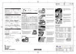
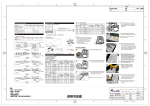
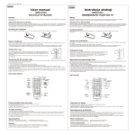
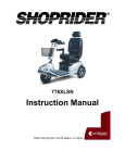
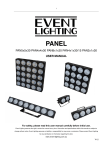
修订
版本 标记 处数
V1
3、Self-provided Installing Tools & Materials
Model No.& Specifications:
Model No.:
M903LB
Rated Power (W/piece):
1.2
Working Voltage (V DC):
12
IP Code:
IP66
Operating Temperature (℃[°F]):
-25~+60[-13~+140]
Storage Temperature (℃[°F]):
-25~+70[-13~+158]
Cutting nipper,Electrical Drill & Drilling Bit
1
03
Self-tapping Screw ST2.9
Unit:mm [in]
04
1、Layout of light box
Thickness of Light Box
(mm)
Parts & Tools:
1、Installation & Connection Instruction:
Distance between
Modules(mm)
Installing Density
(pcs/m²)
Illumination Scope
(lux)
83
2900-3000
dz=80
dx=dy=110
dz=100
dx=dy=140
51
1600-2000
dz=120
dx=dy=175
33
1200-1600
dz=150
dx=dy=220
21
850-1000
dz=180
dx=dy=220
14
600-700
Remarks:
1、Tested with the vinyl cloth of light box which have
the picture,and the transmittance is about 30%
in the white area.
2、The above illumination is the minimum data when
the surface illumination is uniform under this
thickness.
3、The above data was tested by the modules which
the CCT of LED is 6000K.
4、All the above data is for reference only.
Max. Cascade Qty=25PCS
2、Parts&Tools:
05
06
07
Clean the installation surface.
M903LB(25PCS)
Connected the module's wires
to the connector correctly.
(Make sure the color are same
for the connecting)
02
Adjust the modules to the best
installing position,then,press
the modules tightly and fixed it
with self-tapping screws ST2.9.
(Please base on the thickness
of light box to select the size of
self-tapping screw.)
Cut off the excessive modules.
Please do the insulation for the
ending wires with the terminals
or other method.
Cross the wires of connector
through the hole of end cap 2,
then, assemble the end cap 1
and the end cap 2 to Aluminum
frame.
03
Fasten the end caps to
Aluminum with self-tapping
screws (ST.2.2*8).
04
Drill a hole in appropriate
location with an electrical drill,
cross the cable of power supply
through the hole, then, fix the
cable and protect it well.
Mark the installing location for
#1 & #2 fixing buckle inside
light box and fasten it with selftapping screws (ST2.9*10).
05
Terminals
Please ensure the anode and
cathode of wires in the first
module are connected with the
cable of power supply correctly.
Drill a hole in appropriate
places, cross the cable of
power supply through the hole,
then, fix the cable and protect
it well.
06
2、Optional Accessories(Need be ordered)
0.6m Aluminum Frame
End cap 1
Connector with wire
Fixing Buckle1
End Cap 2
Self-tapping Screw ST2.9*6
Self-tapping Screw ST2.2*8
·1·
备注:
1.尺寸:385*210mm;
2.材质:80g书纸;
3.公差:±1mm;
4.灰度双面印刷;
5.虚线不印刷,来料必须从虚线处折好;
Note: Drill a hole with proper force,
otherwise, the panel of the light box
might be broken easily due to the big
force.
2、Assembly and Installation for Modules with Aluminum Frame
1.2m Aluminum Frame
02
2013-03-01 肖云强
Note: Drill a hole with proper force,
otherwise, the panel of the light box
might be broken easily due to the big
force.
Light Box Application Example
1、Modules Installation (No optional accessories)
01
变更者
Note: Please cut from the middle of
wires between modules.
Installation Steps
1、Modules & Accessories
7
日期
1
Application Examples:
Case For Reference
Profile:
Peel off the release paper of double
adehesive tape in the backing of
modules and stick modules on the
installation surface for preliminary
mounting.
1
内容
1.自备物件:增加自攻螺丝ST2.9;
2.模组安装步骤:第4步增加打螺丝步骤;
3.常见故障及排查方法整体修改;
4.注意事项内容整体修改;
5.警告语整体修改; 6.质保申明调整;7.申明修改.
Mark the installation position for
the modules.
01
Fixing Buckle 2
Self-tapping Screw ST2.9*10
·2·
Mark the position for the modules
on Aluminum Frame, then, peel
off the backing paper of double
adhesive in the modules and stick
modules on Aluminum frame, and
then fix the modules with selftapping screws(ST2.9*6).
Put Aluminum frame into #1 &
#2 fixing buckle, then, connect
the adjacent wires with the
terminals according to the
color of wires.
07
·3·
·4·
材 质
二代M903LB说明书
零件名称 启明星
(英文无LOGO)
说明书反面
零件编码
设 计 肖云强 日 期
308-01-107 审 核
图纸 编 号 RD-M903LB-BZ027 标 准 化
页
数
共 2 张
第 2 张 批 准
2013.03.01
表 面处理
日期
重 量
日期
比 例
日期
单 位
N/A
修订
版本 标记 处数
V1
Please ensure the anode and
cathode of wires in the first
module are connected with the
cable of power supply correctly.
Malfunctions & Solutions:
Possible Causes
1.The power supply didn't connect
to the power grid .
All LED
don't works
07
Cut off the excessive modules.
Please do the insulation for the
ending wires with the terminals
or other method.
1.No output form part of power supply.
Part of LED
don't work
Note: Please cut from the middle of
wires between modules.
Remark:
The above installing method is for the standard cascade. The maximum cascade
qty should not more than 25pcs. If the qty of modules is more than 25pcs, please
repeat the installing steps on the above.
.
Brightness
of the LED is
dim or not
even
LEDs are
blinking
1、Caution for installing & using:
1.1 Please check and ensure that the anode & cathode for the module's
wires are connected to power supply output's anode & cathode
accordingly. Otherwise, the product can not work normally.
1.2 Double side adhesive tape is only used for preliminary fixing. Please use
the screws or the neutral silicon sealant to fasten the modules,otherwise,
there will be caused defects such as product shift, fall off and so on.
1.3 The standard cascade quantity is 25pcs modules. The maximum
cascade quantity is 25pcs modules under single-end power feed and
50pcs modules for double-end power feed, prohibited to exceed this
limitation in the actual using.
1.4 Please dispose the exposed wire and the joints with insulation,
waterproof and anti-corrosion.
2、Cautions for others parts selected:
2.1 Please ensure that the output voltage for the using power supply are
12±5%V DC, and the rated power must be reserved 20% than the actual
loading.
2.2 The using power supply must pass safety certification which have the
protect functions in short circuit, over voltage and over current.
2.3 During the installing, please ask the qualified persons to count and
select the suitable cable according to the diameter and length when the
connecting cable need be extended, otherwise, there will be caused low
input voltage to product, or fire hazard due to the cable too hot.
2.The part of modules wrong
connected to the power supply.
Solutions
Power on.
Remove the malfunction
and power on again.
Check the connecting and ensure
the wires are connected correctly.
If the external flexible cable of light box is damaged, please replace it by
the manufacturers or theirs service agent or the qualified persons to avoid
a hazard.
The given data in this manual is based on our standard product. There
may be existed varies with the actual delivery products. Please subject to
the measure data for the actual product.
All illustrations in this user manual are for reference only. Please subject to
the received goods.
The product subject to change or modify without prior notice.
7
Venus Series
LED Modules
User Manual
Check the power supply and
remove malfunctions.
3. The wires for some modules are
connected reversely.
Connect the wires rightly.
1.The loading of power supply is
overloaded.
Use more supplies or replace
it with high power supply.
2.The line losing of the power
supply's wire is too big.
Make sure the operating
voltage of the modules is inside
of ±5% standard voltage.
3 Modules cascaded too many
per the strings.
1
Caution:
2.The power supply is auto
protected because the output is
short circuit.
3. Wrong connected for the wires of
modules.
变更者
Declaration:
Malfunction & Solution Table
Malfunctions
日期
1
1
08
1
内容
1.自备物件:增加自攻螺丝ST2.9;
2.模组安装步骤:第4步增加打螺丝步骤;
2013-03-01 肖云强
3.常见故障及排查方法整体修改;
4.注意事项内容整体修改;
5.警告语整体修改; 6.质保申明调整;7.申明内容修改.
M903LB
Lessen the cascaded qty for
the modules and ensure the
quantity for each electrical
circuit are within the maximum
cascade quantity which allowed.
1.Poor contacted in the joints.
Find out the malfunction and
remove it immediately.
2.Failures in the power supply.
Replace the power supply.
1
Warning:
Prohibited to disassemble, modify this product.
Prohibited to operate the product during power on.
Prohibited to use any organic chemical solvents to contact this product
directly or indirectly.
Installation、repair、maintain must be operated by the professional
persons.Prohibited to operate it by the unprofessional persons.
If the modules don't fasten with the screws, you can use the neutral silicon
sealant to fix it. During the using, please don't seal the light box until the
silicon is solidified fully. Prohibited to use any acid or alkalinity adhesive to
fix the product. Please pay attention to the silicon sealant don't stuck the
surface of the lens.
This product will generate the heat during working. Please consider the
installing density for the modules and use the materials with good heat
dissipation.
1
Warranty:
Warranty:5years or 22000 hours,whichever come first.
Additional Remarks:
The warranty period in the above refer to the product used in the inside of light box with
waterproof.
Please carefully read this manual before using our products and keep it properly
V1.0
·5·
备注:
1.尺寸:385*210mm;
2.材质:80g书纸;
3.公差:±1mm;
4.灰度双面印刷;
5.虚线不印刷,来料必须从虚线处折好;
·6·
·7·
材 质
说明书反面
二代M903LB说明书
零件名称 启明星
(英文无LOGO)
设 计 肖云强 日 期
零件编码 308-01-107
审 核
图纸 编 号 RD-M903LB-BZ027 标 准 化
页
数
共 2 张
第 2 张 批 准
2013.03.01
表 面处理
日期
重 量
日期
比 例
日期
单 位
N/A