1
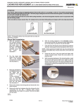
AUTOMATIC OPENER SYSTEM FOR OUTSWING RESIDENTIAL GARAGE DOORS
Installation Manual
Exclusively by:
THIS PAGE INTENTIONALLY LEFT BLANK
TM
Franklin Autoswing Installation Manual
Thank you for buying this product, our company is sure that you will be more than
satisfied with the product’s performance. The product is supplied with
a “Warnings” leaflet and an “Instruction booklet”. These should both be
read carefully as they provide important information about safety, installation,
operation and maintenance. This product complies with the recognized
technical standards and safety regulations.
1) GENERAL OUTLINE
The LIBRA-UL-R control panel is supplied by the manufacturer with standard
setting. Any alteration must be set by means of the incorporated display
programmer or by means of UNIPRO. The Control unit completely supports
the EELINK protocol. Its main characteristics are:
- Control of two low-voltage motors up to 40W power
- Electronic torque setting with obstacle detection
- Limit-switch control inputs
- Separate inputs for safety devices
- Incorporated rolling-code radio receiver with transmitter cloning
The IGEA-BT (24V) is suitable for residential use and has
been designed for swing gates with particularly large gate posts. The drive
arm, built with a special anti-shearing shape, allows the leaves to be moved
when the controller is considerably out of place with respect to the fulcrum
of the leaves. The non-reversible electro-mechanical motor maintains the stop
during closing and opening. The release knob with personalized key, fitted outside
each operator, makes manual operation extremely easy.
2) SAFETY
If correctly installed and used, this automation device satisfies the required
safety level standards. However, it is advisable to observe some practical
rules in order to avoid accidental problems. Before using the automation device,
carefully read the operation instructions and keep them for future reference.
• Keep children, persons and things outside the automation working area,
particularly during operation. An incorrect installation or improper use of the
product can cause damage to persons, animals or things.
• Keep radio control or other control devices out of children’s reach, in order to
avoid any unintentional automation activation.
• Do not intentionally oppose the leaf movement.
• BFT declines all responsibility for any consequences resulting from failure to
observe Good Technical Practice when constructing closing structures (door,
gates etc.), as well as from any deformation which might occur during use.
• The installation must comply with the provisions set out by the following
directives: 89/336/CEE, 73/23/EEC, 98/37/EEC and subsequent amendments.
• Do not attempt to open the gate by hand, if the actuator has not been released
by means of the appropriate release knob.
• Do not modify the automation components.
• In case of malfunction, disconnect the power supply, activate the emergency
release to gain access to the actuator and request the assistance of a qualified
technician (installer).
• Before proceeding to any external cleaning operation, disconnect the main
powers supply and at least one of the battery pole, if fitted.
• Check that grounding is carried out correctly: connect all metal parts for closure
(doors, gates etc.) and all system components provided with an earth terminal.
• Fit all the safety devices (photocells, electric edges etc.) which are needed to
protect the area from any danger caused by squashing, conveying and shearing,
according to and in compliance with the applicable directives and technical
standards.
• Keep the photocell optical components and luminous signal indication devices
clean. Check that the photocells are not obscured by branches or shrubs.
• For any direct assistance to the automation system, request the assistance of a
qualified technician (installer).
• Have qualified personnel check the automation system once a year.
• Entrance is reserved for vehicles, provide a separate entrance for pedestrians.
3) SCRAPPING
Warning: This operation should only be carried out by qualified personnel.
Materials must be disposed of in conformity with the current regulations. In case of
scrapping, the automation devices do not entail any particular risks or danger. In
case of materials to be recycled, these should be sorted out by type (electrical
components, copper, aluminum, plastic etc.).
© 2013 Copyright Real Carriage Door Company, Inc.
4) DISMANTLING
Warning: This operation should only be carried out by qualified personnel. When
the control unit is disassembled to be reassembled on another site, proceed as
follows:
• Disconnect the power supply and the entire electrical installation.
• In the case where some of the components cannot be removed or are damaged,
they must be replaced.
5) FUNCTIONS
FOR THE INSTALLER: Fill in the table with the parameters set, in order to facilitate
future modifications and maintenance operations. The preset values are indicated
between square brackets [ ].
PARAMETER MENU
Automatic Closing Time
Motor 1 torque
Motor 2 torque
Motor 1 slow-down torque
Motor 2 slow-down torque
Opening delay time
Closing delay time
Motor 1 Normal Speed Time
Motor 2 Normal Speed Time
Slow-down speed
Zone
[10s]
[50%]
[50%]
[45%]
[45%]
[1s]
[1s]
[15s]
[15s]
[0]
[0]
___
___
___
___
___
___
___
___
___
___
___
LOGIC MENU
TCA (Automatic Closing Time)
3 steps
Impulse lock on opening
Rapid closing
Photocells on opening
Photocell test
No. motors in operation
Lock hold
Start / Close
Fixed code
Radio programming
Master
[OFF]
[OFF]
[OFF]
[OFF]
[OFF]
[OFF]
[OFF]
[OFF]
[OFF]
[OFF]
[ON]
[OFF]
___
___
___
___
___
___
___
___
___
___
___
___
WARNINGS
Correct controller operation is only ensured when the data contained
in the present manual are observed. The company is not to be held
responsible for any damage resulting from failure to observe the
installation standards and the instructions contained in the present
manual.
The descriptions and illustrations contained in the present manual are
not binding. The Company reserves the right to make any alterations
deemed appropriate for the technical, manufacturing and commercial
improvement of the product, while leaving the essential product features
unchanged, at any time and without undertaking to update the
present publication.
ATTENTION! The IGEA-BT model controller is not equipped with mechanical
torque adjustment. It is compulsory to use a control panel of the same
manufacturer, in compliance with the basic safety requirements of directives
73/23/CEE, 89/336/CEE, 89/37/CEE equipped with appropriate electric
adjustment of the torque.
Correct controller operation is only ensured when the data contained
in the present manual are observed. The company is not to be held
responsible for any damage resulting from failure to observe the
installation standards and the instructions contained in the present
manual.
The descriptions and illustrations contained in the present manual are
not binding. The Company reserves the right to make any alterations
deemed appropriate for the technical, manufacturing and commercial
improvement of the product, while leaving the essential product features
unchanged, at any time and without undertaking to update the
present publication.
3
TM
Franklin Autoswing Installation Manual
Table of Contents
The table of contents are listed to assist you locating a desired section. We do however
strongly suggest reading the entire instruction manual before attempting installation. Note
that this manual is for outswing garage doors. IMPORTANT! This installation manual is
designed as a supplement to the BFT product manuals. Be sure to read the safety
information in all product literature associated with this opener system, as well as comply
with all of the specifications they contain.
General Information
Technical Specifications
Manual Operation Mode
Typical System Overview
Motor Installation
Limit Switch Installation
Mounting the Control Housing
Wiring the Motor
Master Wiring Diagram
General Programming
Installing the Motor Cover
5
6
7
8-9
10
11
11
12
13
14
Appendices
Programming the Remotes
Optional Battery Backup
Door Top Radius Table
Alternative Mounting
Optional Accessories
15 (Appendix A)
16 (Appendix B)
17 (Appendix C)
18 (Appendix D)
19 (Appendix E)
For all programming parameters, please refer to the following BFT product manuals:
LIBRA-UL-R Control Panel
Manual last revised 7/7/2015
4
© 2013 Copyright Real Carriage Door Company, Inc.
TM
Franklin Autoswing Installation Manual
Specifications
MODEL:
FRANKLIN (IGEA-BT)
Mounting Clearance
7.5" above lowest part of door jamb
Voltage
24 V
Power supply
120 V 60 Hz single-phase
Absorbed power
0.05 hp (40 W)
Opening or closing time
15 s
Impact reaction
Torque limiter on control panel
Manual release
Release knob with personalized key
Operating cycle
Intensive Use
Environmental conditions
5oF to 140oF
Degree of protection
IP44
Operator Weight
35 lbs
Door leaf max length
Up to 10 ft
Door leaf max weight
Up to 550 lbs
Door leaf max surface area
120 ft2
Maximum open angle
Up to 125o
6”
14 1/16”
© 2013 Copyright Real Carriage Door Company, Inc.
7 1/4”
5
TM
Franklin Autoswing Installation Manual
Manual Operation Mode
In the case of power failure or operator malfunction, manual operation mode can be carried out
by turning the external release knob with personalized key.
Outside
Inside
Left Motor
Right Motor
For LEFT motor (as viewed from inside):
For RIGHT motor (as viewed from inside):
1. Turn key clockwise
2. Turn release knob counter-clockwise
3. Turn key back to keep in release position
4. Push/pull door slowly to open or close
5. Reverse steps to re-activate auto-mode
1. Turn key clockwise
2. Turn release knob clockwise
3. Turn key back to keep in release position
4. Push/pull door slowly to open or close
5. Reverse steps to re-activate auto-mode
NOTE: When working with limit switches, the
key cannot be used to manually release motor.
To release, flip the black lever (pictured at
right) and swing the door. The lever must be
held down while swinging as it is spring loaded.
6
© 2013 Copyright Real Carriage Door Company, Inc.
TM
Franklin Autoswing Installation Manual
Typical System Overview
Below is an example of typical component placement and wiring. Please note that the Control Housing
must have holes drilled into it to run the wires. UL Listed stress-relief connectors are recommended. Be
careful not to damage the panel when drilling into the housing! It is a good idea to remove the panel
while drilling. Refer to “Master Wiring Diagram” for more detailed views of Control Panel connections.
Surge protection and a dedicated circuit are encouraged.
A. Control Housing (dims 7.25” x 8.75” x 3.5”)
*Motors are low voltage. Use braided wire.
B. Left Motor
Increase wire gauge if motors mounted
C. Right Motor
more than 20’ from control housing.
D. Receiver Photoeye
E. Transmitter Photoeye
**From lowest part of jamb to ceiling line.
F. Wall Pushbutton
G. 4-Button Remote Transmitter (2)
H. Antenna (for extra range applications)
© 2013 Copyright Real Carriage Door Company, Inc.
7
TM
Franklin Autoswing Installation Manual
Installation of Motor
TIP: Before mounting, refer to “Typical System Overview” for prewiring. For a very ‘clean’
installation, mount the unit directly on the head casing (if flat profile). Note that this motor
positioning is for outswing doors only.
1. Remove the cover to the motor and set aside.
2. Remove the motor from the base plate by loosening the 4 bolts on the bottom of the motor.
3. Position the base plate (note that body of the motor should extend toward the side jamb) about 7” from the edge
of the door*. Level the plate and mark the locations of the holes. TIP: For most applications, centering the bottom
row of holes on the jamb makes for the most secure installation.
*NOTE: There are limitations for certain arch-top radii relative to the door width. See table in
APPENDIX C for allowable radii, and APPENDIX D for more help in positioning.
4. Level and mount the plate with minimum 3/8” x 4” lag bolts (not supplied). For proper arm clearance, the bottom
of the plate must no higher than the lowest part of the jamb. Always make certain that the lag bolts penetrate solid
header and/or blocking material.
5. Re-attach the motor to the base plate and tighten securely. Be sure that the motor is seated properly in its plastic
housing.
7”
7”
Left base plate position, square-top
door (interior view)
8
Left base plate position, arch-top
door (interior view)
© 2013 Copyright Real Carriage Door Company, Inc.
TM
Franklin Autoswing Installation Manual
Installation of Motor (Continued)
6. Assemble the articulated lever arm and door coupling as shown in fig. 1. Connect straight arm and door coupling to
curved arm using plastic sleeve (K) and washer (L). Secure together with rolled pin (M). The dashed arm indicates
the setup for the right motor (viewed from inside).
7. Slide the assembled arm onto the transmission shaft at the base of the motor, and fasten it using the long pin (N)
and C-ring (O).
8. Manually release the operator (See “Manual Operation Mode”).
9. Open the door to the desired ‘fully open’ point (approx 105 degrees is recommended). With a measuring tape,
mark the centerline of the door mounting bracket at 40” from the center of the shaft (fig. 2). Making sure that the
arm is level, Mount the arm to the door with #14 x 1-1/2” pan head screws (not supplied)
10. Check clearance and movement by swinging door slowly.
11. Relock the motor (take out of manual release mode).
12. Repeat these steps for the other leaf, if installed.
NOTE:
1.5” dimension is an
approximation only
O
N
K
L
M
Fig 1. Arm Assembly
© 2013 Copyright Real Carriage Door Company, Inc.
Fig 2. Arm positioning
9
TM
Franklin Autoswing Installation Manual
Installation of Limit Switches
1. Install the limit-switch refernce cams as
shown in fig. 3. Install the full cam on top of
the metal shaft, then install the ring cam on
top of the full cam. Do not fully tighten the
FULL CAM
RING CAM
fixing screws.
2. When the door is fully open, rotate the
corresponding cam (fig. 4), until you hear a
‘click’ indicating the limit switch has been
depressed, then lock it in position by
tightening the appropriate screws. Repeat for
the fully closed position. Refer to “Manual
Operation Mode” to manually swing the door.
3. Swing the door slowly to its open and close
positions, listening to see that the ‘click’ of
the limits switch occurs where desired. Note
Fig 3. Limit Switch installation
that the left motor’s cams (close vs open) are
inverted from those of the right motor.
Adjust as necessary.
OPEN LIMIT CAM
CLOSE LIMIT CAM
CLOSE LIMIT CAM
OPEN LIMIT CAM
LEFT MOTOR
(viewed from inside)
CLOSE LIMIT
SWITCH
OPEN LIMIT
SWITCH
OPEN LIMIT
SWITCH
CLOSE LIMIT
SWITCH
RIGHT MOTOR
(viewed from inside)
Fig 4. Limit Switch functions
10
© 2013 Copyright Real Carriage Door Company, Inc.
TM
Franklin Autoswing Installation Manual
Mounting the Control Housing
1. Locate the control housing containing the LIBRA-UL-R panel.
2. For mounting, the rear of the housing must be predrilled. Refer
to fig. 5 for the locations of the holes to be drilled.
3. At this time, plan where you would like to run the wiring into
the housing and predrill for stress-relief connectors. NOTE! Be
careful not to damage the panel when drilling into the
housing! It is advisable to remove the panel while drilling.
4. Mount the housing securely, using either screws or drywall
anchors (not supplied). Be careful not to damage any wires or
components of the board. (See “Typical System Overview” for
suggested location of the housing)
Fig 5. Mounting locations
Wiring the Motor
1. Locate the stress relieving cord-grip.
2. Attach connecting nut (F) to grip body (G). Tighten securely
using finger pressure only.
3. Slip compression nut (H) over a length of 16/3 (16 Gauge,
3 strand) motor wire and thread wire through the
assembled cord-grip.
4. Tighten the compression nut (H) with finger pressure only.
5. Refer to “Master Wiring Diagram” to wire the motor to the
LIBRA-UL-R control panel.
6. For basic programming see “General Programming.” For
advanced parameters, please see the BFT “LIBRA-UL-R
Installation and User’s Manual”
WIRE
USE
min 16/3 wire*
min 22/4 wire
min 22/2 wire
connecting motors to control panel
connecting RX photoeye to control panel
connecting TX photoeye to control panel
F
G
H
Fig 6. Stress relief connector
*Use stranded wire. Increase gauge if motors more than 20’ from panel
© 2013 Copyright Real Carriage Door Company, Inc.
11
TM
Franklin Autoswing Installation Manual
Master Wiring Diagram
Note:
The antenna is not
necessary for normal
operation. Use as a signal
booster for long range or
thick masonry walls.
POWER
GROUND
LINE IN
NEUTRAL
14 Ga. Minimum
120VAC
Important Note:
Use of surge protection and a
dedicated circuit is encouraged
to protect the system from
harmful fluctuations in current.
Terminals may be hardwired or
installer may wire a ‘pigtail’
cord into terminals.
CO-AXIAL SHEILD
ANTENNA CORE
Important Note:
Jumper between
terminals 15 and 18 must
be removed after adding
photoeyes. The jumper
from 15 to 17 remains.
Test operation before
installing photoeyes and
removing jumper.
Note: Terminal strip JP8 (No’s
3-20) is ‘press fit’ and may be
removed for ease of wiring.
22 Ga. minimum
LEFT MOTOR / DOOR
16 Ga. Minimum
(stranded)
Increase wire
gauge if motors
more than 20’
from Control Panel
RIGHT MOTOR / DOOR
22 Ga. minimum
GRN
BLK
WHT
Important Note:
The wiring shown will activate the left door opening first
(viewed from inside). If you require the right door to open
first, swap wires 3&6, 4&7, and 5&8 at the control panel.
It is advised to wire the system and test operation before
installing photoeyes.
12
WALL
SWITCH
BLK
GRN
WHT
PHOTOEYES
Important Note:
With the photoeyes installed,
the door system should stop
and reverse if obstructed
when closing. If the system
reverses when obstructed
when opening, double check
the motor wiring at left.
Photoeye fault is indicated by
‘PhOt’ on the LCD display.
Adjust the eyes until the fault
code clears.
© 2013 Copyright Real Carriage Door Company, Inc.
TM
Franklin Autoswing Installation Manual
General Programming
The Franklin Autoswing comes “out of box” with preprogrammed defaults that allow the unit
to function without further programming needed. There are, however a few steps that can
increase the degree of safety and flexibility of the system. For a list of all programming
parameters, see the “LIBRA-UL-R Installation and User’s Manual” pages 13-17.
AUTOSET
Automatically adjusts the torque to the minimum required to operate the door. NOTE: Before you
use this setting, you MUST have the system fully operational and stopping at its limits in the proper
place, etc.
Programming is as follows:
Press “OK” button twice
Scroll with minus (-) button down to “AUtoSEt”
Press “OK” to activate.
Once activated, the door will execute an opening maneuver, followed by a
closing maneuver. NOTE: DO NOT obscure photoeyes or give any open/stop
commands during this phase. Upon successful completion, the display will read
“OK”. If “KO” is displayed instead, Autoset was not successfully programmed.
Manually check the operation of the door, as well as check the limit switches,
before executing Autoset again. Press minus (-) and plus (+) together to exit to
preceding menu, repeat until the display switches off.
WARNING! During the Autoset phase, obstacle detection functions are not
active, so the installer must control the automation movement and prevent
people or things from entering the working range of the doors. For emergency
shutdown, pull the main fuse located above the 120V terminal.
Main Fuse
CLOSING DELAY TIME
Allows user to set the operational closing delay between Motor 1 and Motor 2 between 1 and 10
seconds (default is 1 second). Useful if the door that opens first is limited in how wide it can open with
respect to the other door.
Programming is as follows:
Press “OK” button three times
Scroll with minus button down to “cLS dELAy tIME”
Press “OK” to enter menu
Press minus (-) for less delay, plus (+) for more delay (max 10 seconds)
Press “OK” to confirm
Press minus (-) and plus (+) together to exit to preceding menu, repeat until the display switches off.
© 2013 Copyright Real Carriage Door Company, Inc.
13
TM
Franklin Autoswing Installation Manual
Installing the Motor Cover
1. Hold the cover over the motor, with the front of the cover angled toward you. Rock the cover rearward (fig. 7) until
the cover is seated. The cover must be installed in this way so that the Manual Operation cam engages properly
with motor (fig 8).
2. Test the manual release mechanism as described in “Manual Operation Mode.”
3. Fasten the cover with the 4 screws provided (fig. 9).
Fig 7. Seating the cover
LEFT MOTOR CAM
RIGHT MOTOR CAM
Fig 8. Manual Operation Cams
14
Fig 9. Securing the cover
© 2013 Copyright Real Carriage Door Company, Inc.
TM
Franklin Autoswing Installation Manual
Appendix A
(Programming the Remotes)
1. Press “OK” button twice Turn on the display
2. Scroll with minus button (-) down to “rAdio”
3. Press “OK” (the display will read “Add StArt”)
4. Press “OK” (the display will read “hIddEn bUtton”)
5. Press and hold the hidden button on the transmitter (see fig. 10) until the display reads “rELEASE”
6. Release the hidden button (the display will read “dESIrEd bUtton”)
7. Press the button you want to activate the door with (the display will read “ok 01”, “ok 02”, etc)
8. The display will now read “Add StArt”, repeat the procedure from step # 4 to install other transmitters.
9. Switch off the display by simultaneously pressing “+” and “-” buttons twice. Your transmitters are now ready to
use.
Fig. 10 Hidden Button
On 4-button remotes, the hidden button
is activated by pressing the two forward
buttons closest to the LED at the ‘front’
of the remote.
© 2013 Copyright Real Carriage Door Company, Inc.
15
TM
Franklin Autoswing Installation Manual
Appendix B
(Optional Battery Backup)
1. Secure the battery housing to solid blocking using screws or lag bolts (not provided)
2. Wire the batteries into the terminal strip using 14 ga. (minimum) wire in series as shown below, taking care to
observe polarity.
3. Splice terminal 3 to the wire that connects “0V” on the transformer to “JP2” on the LIBRA-UL-R panel. Always use
UL listed electrical connective devices.
4. Remove the connector between “25V” on the transformer and “JP5” on the LIBRA-UL-R panel.
5. Connect terminal 4 to “25V” on the transformer.
Batteries
16
© 2013 Copyright Real Carriage Door Company, Inc.
TM
Franklin Autoswing Installation Manual
Appendix C
(Door Top Radius Table)
Use the chart below to determine if your arched door can be automated with the
Franklin Autoswing™.
Double Door
Width (ft-in)
Minimum
Radius (in)
Max Segment
Height*(in)
6' 0"
90"
7-1/2"
6' 6"
97-1/2"
8-1/8"
7' 0"
105"
8-3/4"
7' 6"
112-1/2"
9-3/8"
8' 0"
120"
10"
8' 6"
127-1/2"
10-1/2"
9' 0"
135"
11-1/4"
9' 6"
142-1/2"
11-7/8"
10' 0"
150"
12-1/2"
10' 6"
157-1/2"
13-1/8"
11' 0"
165"
13-3/4"
11' 6"
172-1/2"
14-3/8"
12' 0"
180"
15"
12' 6"
287-1/2"
15-5/8"
13' 0"
195"
16-1/4"
13' 6"
202-1/2"
16-7/8"
14' 0"
210"
17-1/2"
14' 6"
217-1/2"
18-1/8"
15' 0"
225"
18-3/4"
15' 6"
232-1/2"
19-3/8"
16' 0"
240"
20"
*This is the vertical distance from the springline to
the peak of the arch
© 2013 Copyright Real Carriage Door Company, Inc.
17
TM
Franklin Autoswing Installation Manual
Appendix D
(Alternative Mounting)
With some arched doorways, proper motor positioning
can be a little challenging. Door construction, radius,
and overall width can all affect motor placement. Below
is a guide designed to assist you in mounting while
allowing for proper geometry of the opener system’s
articulated lever arm.
1. Fashion a plywood or cardboard disk that you can use
as a template. The disk should be 8” in diameter, with
a 1-7/8” diameter hole cut out of the center.
2. Set the disk on your assembled lever arm as show
below. You will not need the motor or base plate. With
your door leaf in the fully open position (approx 105
degrees), move the disk along the wall and door
coupling along the door until you achieve the
dimensions at right. For best results, the straight leg of
the lever arm should be as close as possible to the
arched jamb (1/2” min) .
3. Mark the center point of the bracket on the door and
the tangent point of disk on the wall.
4. Drop the motor into the base plate and hold on wall at
Lever arm
anticipated mounting location. Dry fit the lever arm
and adjust height of entire assembly as necessary for
proper arm clearance when fully open.
5. Mark the height of base plate. Mount the plate as
described in “Installing the Motor,” and continue with
normal installation.
NOTE: Securely mounting the base plate is very
important. If needed, drill additional mounting holes
to affix the plate directly to the jamb.
© 2013 Copyright Real Carriage Door Company, Inc.
Disk
18
TM
Franklin Autoswing Installation Manual
Appendix E
(Optional Accessories)
Wireless Outdoor Keypad
With an outdoor keypad you enjoy secure exterior access
to your doors without a remote. Operates up to 10 doors.
Wireless Wall Button
This upgraded wall button is wireless, so no wiring is
necessary for installation. Operates up to 4 doors.
Battery Backup
Be prepared for unexpected power outages with a battery
backup. Dimensions 7.75” x 9.25” x 3.75”. Battery Backup
powers one Franklin system only.
ECOSOL Solar Power
Get your garage door off the grid with Ecosol solar
conversion. Allows up to 3 weeks of residential use without
sunshine. Optional accessory can charge batteries from line
voltage.
®
19
HOMELINK Compatibility
Toss out your handheld remote controls and operate your
garage door system directly from your car with the
Homelink compatibility option.
© 2013 Copyright Real Carriage Door Company, Inc.
For questions,
please contact us for technical support
800-694-5977
TM
9803 44th Avenue NW, Gig Harbor, WA 98332