1
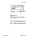
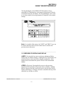
SECTION 3
USING THE KEYPAD/DISPLAY
The Keypad/Display of the HSM-DUCTOR contains 24 keys
consisting of 12 function keys, and a numeric keypad and a 2 line by
40 character back-lit LCD display. The Keypad/Display can be used
to view data, modify all set-up parameters or adjust the color control
settings.
Note: For virtually all the menus, the "NEXT" and "PREV" keys can
be used to advance to the next item of the menu or return to the
previous item on the menu.
________________________________________________________
3.1 OVERVIEW OF KEYPAD AND DISPLAY
<NEXT>: Pressing this key moves to the next adjustment field or
displays the next menu or display. Holding this key depressed for one
second will move to the next field or display continuously. If all
displays have been shown the system will exit to the main default
display.
<PREV>: (Previous): Pressing this key moves to the previous
adjustment field or displays the previous menu or display. Holding
this key depressed for one second will move to the previous field or
display continuously. If display selection is returned to the top of the
order this key will have no effect.
HSM-DUCTOR User’s Manual
SYSTEMS Electronics Group
- 17 -
SECTION 3
USING THE KEYPAD/DISPLAY
<INC>: (Increment): Pressing this key once increments the currently
selected field value by one. Holding this key depressed for one
second will increment the currently selected field continuously. This
key is only active in the adjustment mode.
<DEC>: (Decrement): Pressing this key once decrements the
currently selected field value by one. Holding this key depressed for
one second will decrement the currently selected field continuously.
This key is only active in the adjustment mode.
<DISPLAY DATA>: (Cycle Counts): Pressing this key displays the
total number of cycles for each ductor. Pressing this key the first time
displays the counts for ductors 1 and 2, press the <NEXT> to advance
to the next display, <PREV> to retard to the previous display. The
display will automatically advance to the next display approximately
every 7.5 seconds until all cycling counts have been displayed.
<RESET COUNTS>: Pressing this key allows the total cycle counts
for each ductor to be reset. A prompt is displayed asking which
ductor to reset. Enter the corresponding number of the ductor to reset
that individual ductor count. Press <0> to reset all the ductor counts.
Press <ESC> to reset none of the ductor counts and return to the
main menu.
<SET UP>: Pressing this key allows the user to set-up the ductor
configuration parameters. This key is only active when set-up has
been enabled.
<ALARM RESET>: Pressing this key resets any active ductor fault
alarms (feedback detected failure). This key is only active when the
main default display or fault display is active
<COLOR CONTROL>: Pressing this key allows the operator to
select a new label number, adjust the “Cycle” and “On” durations,
independently for each ink stations or program a new label from
scratch. This key is passcode protected when the “Set-Up” switch is
not disabled.
When the “Color Control” key is depressed, the label selection screen
is displayed. The operator may enter in a new label number or simply
press the <NEXT> or <ENTER> keys to advance to the station
adjustment menus.
HSM-DUCTOR User’s Manual
SYSTEMS Electronics Group
- 18 -
SECTION 3
USING THE KEYPAD/DISPLAY
A number of different screens are shown on the display of the HSMDUCTOR. The primary screen displays the machine cpm. Other
screens displayed include the cycling counts data display, reset
cycling counts display, passcode entry menu and the set-up menu.
________________________________________________________
3.2 RECOMMENDED PROCEDURE FOR USING THE
HSM-DUCTOR
On the original mechanically cammed ductor, the keys on the
fountain were used both to control the areas on the can that the ink
was to be applied as well as the color quality (light/dark) of the color.
Thus the keys were adjusted proportionally to where on the can the
color was located as well as how much area the color covered and
how dark the color was.
With the pneumatic ductor, the color quality is now controlled by the
frequency and duty cycle of the ductor (as set by the operator through
the Keypad/Display). The fountain keys are simply used to define the
locations (top, bottom, middle, etc.) the color is located on the can.
The keys should not be adjusted proportional as before, but should be
either closed at areas where there will be no color on the can, or
opened (a predefined number of turns) on areas where the color is
located on the can.
This allows label changes to occur quicker by simply setting the keys
open or closed at the locations required on the can, and selecting the
label number for the respective label on the Keypad/Display (thus
setting the color quality to the same level as previously set for that
label).
The M4503 is capable of saving the settings for up to 100 labels. As
different labels are run, the labels programmed are added to the
internal data base. When a programmed label is run again, simply
recall the label number and the ductors will oscillate at the same
frequency and duty cycle the last time the label was run. The only
additional set-up required at label change over is to set the keys open
and closed at the required areas on the can.
The following sections describe the recommended procedure for
setting up a label and the recommended procedure for a label change
over using a label, which has previously been programmed into the
color control.
HSM-DUCTOR User’s Manual
SYSTEMS Electronics Group
- 19 -
SECTION 3
USING THE KEYPAD/DISPLAY
________________________________________________________
3.3 SET-UP PNEUMATIC DUCTOR PARAMETERS
This menu is activated when the "Set-up” key is pressed. The
following set-up parameters may then be adjusted or viewed:
Note: For virtually all the menus, the <NEXT> and <PREV> keys
can be used to advance to the next or previous parameter respectively.
To change the currently displayed parameter, simply enter the new
value on the numeric keypad and press <ENTER>. The value will be
entered and the next parameter will automatically be displayed.
When the last parameter in a section is entered, the primary set-up
menu is again displayed. Pressing <ESC> at anytime will exit back to
the main display menu.
The following parameters are used to define the ductor configuration:
Maximum “Cycle” Duration: The maximum “Cycle” duration is
set to 1/10th of a can resolution. The range of this parameter is from
140 to 650 and defines the upper limit or the longest amount of time
between ductor cycles. Care should be taken not to set this parameter
too low, as this would restrict the operators range of adjustment. The
“Cycle” duration is set individually for each ink station and is the rate
at which ink is transferred from the fountain roll.
Maximum “On” Duration: The maximum “On” duration is set to
1/10th of a can resolution. The range of this parameter is from 0 to
200 and defines the upper limit or the longest amount of time the
ductor roll can be in contact with the fountain roll. The “On”
duration is set individually for each ink station and is the amount of
time the ductor roll is in contact with the fountain roll.
Response Time Compensation: The response time
compensation parameters is used to adjust the “On” duration based on
the difference between the “ON” and “off” response time of the
ductor solenoid. As and example, if the “ON” response time were 40
msec. and the “off” response time was 15 msec., then this parameter
would need to be set to 25 msec.
The “ON” response time is defined as the time ductor is activated to
the time it comes in contact with the fountain roll. The “off” response
time is the time the ductor is deactivated to the time it lifts off of the
fountain roll. If the optional feedback sensors are to be used, this
parameter should be set to zero.
HSM-DUCTOR User’s Manual
SYSTEMS Electronics Group
- 20 -
SECTION 3
USING THE KEYPAD/DISPLAY
Color Gain: This parameter allows the color density to be increased
proportionately up or down as a function of machine speed. The valid
range of this parameter is 50% to 150% per 2000 CPM. When set to
100%, no increase or decrease, as a function of speed will occur.
When set to 50%, the color density will drop 50% from 0 to
2000CPM. When set to 150% the color density will increase by 50%
from 0 to 2000CPM. This parameter is used to compensate for ink
atomization (misting) as a function of speed (higher speed =
proportionately higher ink misting).
Feedback Enable (stations 1 – 8): This parameter enables the
individual feedback faults and should only be enabled when the
optional feedback sensors are used. Once enabled, the M4503 will
verify that the ductor is cycling properly. If a ductor is not detected
as cycling properly, the “Ductor Feedback Fault” is energized,
indicating a problem with the ductor cycling control.
If a “Ductor Feedback Fault” does occur, the ductors should be
manually activated to verify proper cycling operation, as well as, the
sensor for proper feedback operation. The feedback sensor should be
set such that it is only “ON” when the ductor is in contact with the
fountain roll.
HSM-DUCTOR User’s Manual
SYSTEMS Electronics Group
- 21 -
SECTION 3
USING THE KEYPAD/DISPLAY
________________________________________________________
3.4 SELECTING THE LABEL NUMBER
To select a label, perform the following:
1) Press the <COLOR CONTROL> key to enter the adjustment
mode.
2) If the prompt "ENTER PASSCODE:" is displayed, enter the
corresponding 1 to 5 digit passcode on the numeric keypad and
press <ENTER>. If the prompt "ENTER PASSCODE:
INCORRECT PASSCODE" is displayed, enter the correct
passcode and press <ENTER>.
3) The "LABEL" field is displayed. Enter a new label (0-99) on the
numeric keypad and press <ENTER> or press the <NEXT> key
to use the existing label.
Note: The decorator must be stopped in order to change the label
number.
4) If no further changes are to be made to the ink stations settings,
press <ESC> to exit.
________________________________________________________
3.5 LIGHT / DARK COLOR ADJUSTMENT OF INK STATION
The “On” duration and “Cycle” duration for each ink station can be
set individually for each label number. The “On” duration can be
viewed as a “Course” adjustment and the “Cycle” duration can be
viewed as a “Fine” adjustment. Observe how changing either the
“On” duration or “Cycle” duration, changes the relative “Color
Density”.
Note: If an ink station is not used, simply set its “On” duration to
zero to disable the cycling operation.
Use the “Color Density” display as an indication of the amount of ink
being transferred by the ductor. Different settings of the “On” and
“Cycle” durations will achieve the same “Color Density”.
HSM-DUCTOR User’s Manual
SYSTEMS Electronics Group
- 22 -
SECTION 3
USING THE KEYPAD/DISPLAY
Note: To reduce “Light” and “Dark” variations in print between
cycle times, adjust both the “On” duration and “Cycle” duration down
to achieve the same “Color Density”.
For a new label or existing label that needs color adjustment, perform
the following:
1) Press the <COLOR CONTROL> key to enter the adjustment
mode if not already in adjustment mode.
2) To select the desired ink station for adjustment, press the
<NEXT> or <PREV> keys until the desired ink station is
displayed.
3) To lighten the color, start by decreasing the “On” duration or
increasing the “Cycle” duration. Watch the “Color Density” to
see how your adjustments change this value. Remember, think of
the “On” duration as a “Course” adjustment and the “Cycle”
duration as a “Fine” adjustment.
4) To darken the color, start by increasing the “On” duration or
decreasing “Cycle” duration. Watch the “Color Density” to see
how your adjustments change this value. Once again, think of the
“On” duration as a “Course” adjustment and the “Cycle” duration
as a “Fine” adjustment.
5) Check the color quality and continue to increase or decrease the
“Color Density” until the desired color quality is achieved.
6) Perform steps (2) through (4) above for all ink stations used as
necessary.
7) Once the label quality is satisfactory, press the <ESC> key to exit
the adjustment mode and save the changes for the selected label.
HSM-DUCTOR User’s Manual
SYSTEMS Electronics Group
- 23 -
SECTION 3
USING THE KEYPAD/DISPLAY
________________________________________________________
3.6 CHANGE OVER USING AN EXISTING LABEL IN THE
HSM-DUCTOR
When a label is to be run again, perform following to set-up the label
at change over.
1) Select the respective label number on the Keypad/Display.
2) Set the keys open (predefined number of turns, a number which is
used for all ink stations on all labels) on the areas of the can that
will have ink and closed on areas that will not have ink.
3) Run the machine and verify that ink is being distributed on the can
correctly. The ink will be metered at the same rate as previously
set the last time the label was run. Thus only minor adjustments
to the keys may be necessary to assure that ink is not distributed
to areas where no color is applied (resulting in slinging due to ink
build up).
________________________________________________________
3.7 VIEWING THE TOTAL NUMBER OF CYCLES FOR EACH
DUCTOR
The total number of cycles for each ductor is accumulated in the
M4503. This is used for life expectancy and predictive maintenance
purposes to determine when air cylinders or solenoids should be
replaced. To view the number of cycles for each ductor, perform the
following:
1) Press the <DISPLAY DATA> key. The total number of cycles
for ductors 1 and 2 will be displayed.
2) To view the counts for ductors 3 and 4, press <NEXT> key. The
counts for ductors 3 and 4 will be displayed.
3) Continue pressing the <NEXT> key to view the counts for the
remaining ductors.
HSM-DUCTOR User’s Manual
SYSTEMS Electronics Group
- 24 -
SECTION 3
USING THE KEYPAD/DISPLAY
________________________________________________________
3.8 RESETTING THE TOTAL NUMBER OF CYCLES FOR
EACH DUCTOR
To reset the total number of cycles for each ductor, perform the
following. Note this procedure should only be performed when
replacing a component (air cylinder, solenoid, etc.) for a particular
ductor.
1) Press the <RESET COUNTS> key. The "Reset Ductor Cycle
Counts" screen will be displayed.
2) To reset an individual ductor count, press the corresponding
number of that ductor (1 to 8) and press <ENTER>. The cycle
count for that ductor will be reset.
3) To reset the counts for all the ductors, press <0> and then
<ENTER>.
4) To exit out of the screen without resetting any of the ductor
counts, press <ESC>.
HSM-DUCTOR User’s Manual
SYSTEMS Electronics Group
- 25 -