1
Smart One
DOCSIS Cable Modem
User's Manual
Model Number : CMX300V2
DOCSIS 1.0/ 1.1 Equivalent Cable Modem
FCC Statement
This device complies with Class B Part 15 of the FCC Rules. The device generates,
uses and can radiate radio frequency energy and, if not installed and used as instructed,
may cause harmful interference to radio communication. Only shielded USB and
Coaxial cables are to be used with this device in order to ensure compliance with FCC
emissions limits. Accessories connected to this device by the user must comply with
FCC Class B limits. The manufacturer is not responsible for any interference which
results from use of improper cables, or which results from unauthorized changes or
modifications to the device.
"A Minimum 26 AWG Line Core should be used for connection to the cable modem"
Warranty
Items sold by manufacturer/distributor/agent, hereinafter called "Seller", are warranted
only as follows: Except as noted below Seller will correct, either by repair or
replacement at its option, any defect of material or workmanship which develops
within one year after delivery of the item to the original Buyer provided that evaluation
and inspection by Seller discloses that such defect developed under normal and proper
use. Repaired or replaced items will be further warranted for the unexpired term of
their original warranty. All items claimed defective must be returned to Seller,
transportation charges prepaid, and will be returned to the Buyer with transportation
charges collect unless evaluation proves the item to be defective and that the Seller is
responsible for the defect. In that case, Seller will return to Buyer with transportation
charge prepaid. Seller may elect to evaluate and repair defective items at the Buyer's
site. Seller may charge Buyer a fee (including travel expenses, if needed) to cover the
cost of evaluation if the evaluation shows that the items are not defective or that they
are defective for reasons beyond the scope of this warranty.
The Seller makes no warranty concerning components or accessories not manufactured
by it. However, in the event of failure of such a part, Seller will give reasonable
assistance to Buyer in obtaining from the manufacturer whatever adjustment is
reasonable in light of the manufacturer's own warranty. Seller will not assume
expense or liability for repairs made outside the factory by other than Seller's
employees without Seller's written consent.
SELLER IS NOT RESPONSIBLE FOR DAMAGE TO ANY ASSOCIATED
EQUIPMENT, NOR WILL SELLER BE HELD LIABLE FOR INCIDENTAL,
CONSEQUENTIAL, OR OTHER DAMAGES. THIS WARRANTY IS IN LIEU OF
ALL OTHER WARRANTIES EXPRESSED OR IMPLIED INCLUDING THE
IMPLIED WARRANTY OF "MERCHANTABILITY" AND "FITNESS FOR
PARTICULAR PURPOSE."
Trademarks
All trademarks are the property of their respective owners.
i
DOCSIS 1.0/ 1.1 Equivalent Cable Modem
Table of Content
Smart One ............................................................................ i
DOCSIS Cable Modem......................................................................... i
FCC STATEMENT.......................................................................................................................... I
WARRANTY ...................................................................................................................................... I
TRADEMARKS ................................................................................................................................. I
CHAPTER 1 INTRODUCTION.............................................................................................................1
1.1 About This Manual................................................................. 1
Chapter 1: Introduction................................................................................ 1
Appendix A: Cable Modem Specifications .................................................. 1
1.2 General Description................................................................ 1
1.3 Features.................................................................................. 2
CHAPTER 2 BEFORE YOU BEGIN.....................................................................................................2
2.1 System Requirements ............................................................. 2
2.2 Safety Precautions.................................................................. 2
2.3 Unpacking and Inspection ...................................................... 3
2.4 Operation Environment .......................................................... 3
Table 1. Maximum Ratings in Non-Operational or Storage Conditions ........ 3
Table 2. Operational Conditions .................................................................. 3
CHAPTER 3 HARDWARE INSTALLATION .....................................................................................4
CHAPTER 4 ETHERNET INSTALLATION .......................................................................................7
CHAPTER 5 USB INSTALLATION ( OPTIONAL )...........................................................................8
CHAPTER 6 CABLE MODEM LED OPERATION..........................................................................12
APPENDIX A: CABLE MODEM SPECIFICATIONS......................................................................13
Table 4. RF Downstream Specification...................................................... 13
Table 5. RF Upstream Specification........................................................... 13
Table 6. Electrical Specification ................................................................ 14
Table 7. Physical Specification .................................................................. 14
Table 8. Environmental Specification ........................................................ 14
APPENDIX B: QUESTIONS AND ANSWERS ..................................................................................15
APPENDIX C: GLOSSARY .................................................................................................................25
ii
DOCSIS 1.0/ 1.1 Equivalent Cable Modem
iii
DOCSIS 1.0/ 1.1 Equivalent Cable Modem
Chapter 1 Introduction
This chapter provides an introduction to the DOCSIS 1.0/1.1 equivalent Cable Modem
User Guide. In addition, this chapter provides a general description of the Cable
Modem’s product features.
1.1 About This Manual
This manual is divided into the following sections:
Chapter 1: Introduction
Provides a general introduction to the Cable Modem Reference Design.
Chapter 2: Before You Begin
Provides preliminary information needed to understand your product’s installation. We
recommend reading this chapter for instructions on how to make the most of your new
Cable Modem.
Chapter 3: Hardware Installation
Shows you how to install the Cable Modem including instructions for connecting the
Hybrid-Fiber Coax (HFC) cable network, and the data network to your personal
computer’s Ethernet Network Interface Card (NIC) or Universal Serial Bus (USB).
Chapter 4: Ethernet Installation
Shows you how to install the Cable Modem through Ethernet Port.
Chapter 5: USB Installation ( optional )
Shows you how to install the Cable Modem through USB Port.
Chapter 6: Cable Modem LED Operation
Provides operating instructions for using your new Cable Modem.
Appendix A: Cable Modem Specifications
Provides the specifications for the Cable Modem.
Appendix B: Questions and Answers
Provides the answers for questions during the cable modem installation
andapplications.
Appendix C: Glossary
Provides the "Term" definition and explanation for Cable Modem.
1.2 General Description
This is a complete MCNS DOCSIS 1.0/1.1 equivalent Cable Modem product. This
DOCSIS 1.0/1.1 equivalent product works with all existing DOCSIS 1.0/1.1 equivalent
head-end equipment and Multiple Service Operator (MSO) networks.
The Cable Modem interfaces between a Hybrid-Fiber Coax (HFC) network, a
10Base-T/100Base-TX Ethernet NIC(A-MDIX) and an USB port ( optional ) inside
your personal computer.
1
DOCSIS 1.0/ 1.1 Equivalent Cable Modem
1.3 Features
§
§
§
§
§
§
§
§
§
§
DOCSIS 1.0/ DOCSIS 1.1 equivalent
Ethernet 10Base-T/100Base-TX(A-MDIX)or USB (optional) Interface for easy
installation
Status LEDs (Power, Cable, LAN, USB, Activity) or (Power, Cable, LAN, RX,
TX)
QoS
MSO SNMPv3 remote network management
MSO Web Browser management auto detect CM status
Field software upgradeable by MSO
DHCP server support (Auto disable in MSO operation mode)
Provide MIBs DOCSIS1.0/1.1
Supports up to 15 networked clients
If you experience problems with your Cable Modem, please contact your Field
Applications Engineers at your local Sales Office. He or she will be happy to help
you with all of your technical needs.
Chapter 2 Before You Begin
Before installation, please check the following requirements with your computer.
This cable modem equips ETHERNET and USB (optional) interfaces. You can
choose either one to connect to the cable modem or connect Ethernet and USB
simultaneously.
2.1 System Requirements
l System Requirement of Ethernet Connection
1. IBM Compatible, Macintosh or other workstation supports TCP/IP protocol.
2. An Ethernet port supports 10Base-T/100Base-TX Ethernet connection.
3. Subscribed to a Cable Television company for Cable Modem services.
l System Requirement of USB Connection ( optional )
1. IBM Compatible PC with Microsoft Windows 98/2000/Me/XP.
2. PC with available USB Port.
3. Subscribed to a Cable Television company for Cable Modem services.
If using a MSO network, contact your local cable operator to ensure the termination
circuit is removed and service is available.
2.2 Safety Precautions
For your protection, observe the following safety precautions when setting up and
using your equipment. Failure to observe these precautions can result in serious
personal injury and damage to your equipment.
• Make sure the voltages and frequency of the power outlet match the electrical rating
labels on the AC Adapter.
• Do not place any object on top of the device or force it into a confined space.
• Never push objects of any kind through openings in the casing. Dangerous voltages
may be present. Conductive foreign objects could produce a short circuit that could
2
DOCSIS 1.0/ 1.1 Equivalent Cable Modem
cause fire, electrical shock, or damage to the equipment.
• When installing the CABLE MODEM, be sure to observe the anti-static caution in
the installation section of this user’s guide. This will prevent damage to the board
and other components.
• Whenever there is danger of lightning, disconnect the power cable and the
Hybrid-Fiber Coax cable from the cable modem to prevent damage to the unit. The
use of an AC protection device will not completely protect the cable modem product
from damage caused from the transmission across the Hybrid-Fiber Coax network.
2.3 Unpacking and Inspection
Included in the kit is the following:
• Cable Modem
• AC Adapter
• Installation Guide
• Ethernet RJ-45 Cable
• USB Cable ( optional )
• USB Driver Wizard and manual CD-ROM or manual only CD-ROM
• Case Holder
If any items are missing or damaged, please contact your local Sales Office.
2.4 Operation Environment
Tables 1 and 2 define the maximum ratings for the CABLE MODEM.
Table 1. Maximum Ratings in Non-Operational or Storage Conditions
NON-OPERATIONAL OR STORAGE CONDITIONS
Temperature
Humidity
– 10°C to +60 °C
10% to 90% non condensing
Table 2. Operational Conditions
OPERATIONAL CONDITIONS
Temperature
Humidity
0 °C to +40 °C
10% to 90% non condensing
3
DOCSIS 1.0/ 1.1 Equivalent Cable Modem
Chapter 3 Hardware Installation
This chapter describes the proper steps for connecting your new Cable Modem. Please
be sure to follow the steps in the sequence outlined below. Failure to do so could result
in improper operation or failure of your Cable Modem.
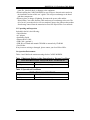
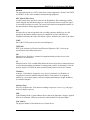
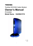
Step 1:
Connect a DOCSIS 1.0/1.1 equivalent cable feed to the F-connector on the back of the
cable modem as illustrated in Figure 1. Ensure that the center conductor of the 75 ohm
coaxial cable is inserted directly into the center of the F-connector. Secure the coaxial
cable by carefully threading the outer shell of the coaxial cable connector onto the
F-connector in a clockwise direction until tight. Be careful not to over-tighten the
connector or you may damage either the connector or the cable modem.
NOTE: To speed up the initial cable modem registration process, the coaxial cable
should be connected to the modem prior to the power connector.
Figure 1. Connecting the Coaxial Cable
Cable Feed (F Connector)
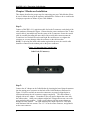
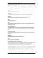
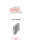
Step 2:
Connect the AC Adapter to the Cable Modem by inserting the barrel-shaped connector
into the mating power connector on the back of the Cable Modem as illustrated in
Figure 2. Exercise carefully to ensure the connectors are properly aligned prior to
insertion and ensure the two connectors engage completely. The cable modem is
shipped with an AC adapter. Remember to use only power adapter that came with
the cable modem. Other power adapters might have voltages that are not correct for
your particular cable modem. Using a power adapter with the wrong voltage can
damage the cable modem. The cable modem power input requires 12 VDC input
with minimum 1000 mA current. The +12 V is on the center connector, and ground is
on the outer connector.
4
DOCSIS 1.0/ 1.1 Equivalent Cable Modem
Figure 2. Connecting the AC Adapter
Power
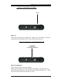
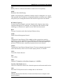
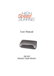
Step 3-a:
Connect the Cable Modem to an IEEE 802.3 10BaseT / 802.3u 100Base-TX Network
using a RJ-45 male-terminated CAT-5 cable as illustrated in Figure 3a.
Figure 3a. Connecting to a Network Interface Card
10/100Mbps
Auto-MDIX Ethernet
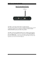
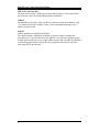
Step 3-b (optional):
Notice: Some serials may not have USB port.
Connect the USB cable to the Cable Modem by inserting the rectangular end of an
USB cable into the USB port of the Cable Modem as illustrated in Figure 3b. Ensure
the connectors lock together by listening for a snap.
5
DOCSIS 1.0/ 1.1 Equivalent Cable Modem
Figure 3b. Connecting the USB Cable
USB port
CAUTION 1: Connecting to More Than one Computer Devices:
This cable modem provides you the feature for Ethernet and USB interfaces to operate
on 2 different computer devices simultaneously. However, you have to obtain
additional IP addresses from your cable service provider.
CAUTION 2: Do not using USB and Ethernet in one computer at the same time.
You are strongly recommended to connect to the Internet using either the Ethernet
port or the USB port only. In most cases CATV ISPs provide one IP address only,
having the USB and Ethernet cables plugged into the cable modem at the same time
might cause you to access the Internet improperly.
6
DOCSIS 1.0/ 1.1 Equivalent Cable Modem
Chapter 4 Ethernet Installation
Setting Up the Computer to Use an Ethernet Connection
The LAN port you are using is auto-negotiating 10/100Mbps (Switch) Ethernet
Interface. You can use the Ethernet port to connect to the Internet with an Ethernet
network device such as NIC/Hub/Switch through RJ45.
Before you connect to and install the cable modem, please set the IP address to
"Obtain an IP address automatically" as below and do ensure the TCP/IP protocol
is installed on your system and configured correctly in your PC.
Following is an example of configuring the TCP/IP Protocol on Windows 98
Operating Systems,
1. Click "Start" button, choose "Settings, and then "Control Panel", Double click on
the "Network" icon click "'Properties".
2. A list of installed network components appears. Look for an entry named TCP/IP.
This entry may be followed by an arrow and a description of the NIC hardware
device installed in the computer. If you don't see "TCP/IP" listed anywhere in the
"The following network components are installed" box, click the "Add" button,
choose "Protocol", and click the "Add" button. Select "Microsoft" as the
manufacturer and then scroll down in the list on the right to find "TCP/IP".
If you see "TCP/IP" listed, proceed to step 4
3. Click the OK button. You will be prompted to insert the Windows 98
installation/upgrade CD.
4. Scroll down in the box until you find a line that says "TCP/IP -> " followed by the
name of your Ethernet adapter. Click on "Properties" and choose "Obtain an
address automatically" which means that your PC has been configured to use
DHCP (Dynamic Host Configuration Protocol).
5. Click OK.
Congratulations! You have successfully set up your new Cable Modem.
CAUTION: Using the Ethernet port allows you to use a hub to connect multiple
computers to the cable modem. To do this, you may need to obtain additional IP
addresses from your cable service provider.
7
DOCSIS 1.0/ 1.1 Equivalent Cable Modem
Chapter 5 USB Installation ( OPTIONAL )
Notice : Some serials of Cable Modem may not have USB port.
Using the USB port to connect to the Internet allows you to install the cable modem
more quickly and easily than connecting to the Internet using the Ethernet port, since
you do not need to install a network interface card (NIC).
Using USB with the Windows 98 or Windows Me Operating System
To use the USB port with Windows 98/Me:
1. Connect USB cable from PC to Cable Modem
2. Connect RF cable and Power on Cable Modem. Wait until Cable Modem register,
it will take from 40 sec to 4 min depends on Network traffic.
3. Cable Modem may reboot if you previously connect it through Ethernet port
4. Windows will prompt new hardware found
5. Insert the Driver CD-ROM
6. Click “Search for the …” then “Next”
7.Select CD-ROM drivers , and click “Next“
8
DOCSIS 1.0/ 1.1 Equivalent Cable Modem
8.
Windows will locate the driver automatically
9.
After windows install the USB driver. Click Finish and Windows will ask for
reboot
Using USB with the Windows 2000 or Windows XP Operating System
To use the USB port with Windows 2000/XP:
1. Connect USB cable from PC to Cable Modem
2. Connect RF cable and Power on Cable Modem.
Wait until Cable Modem register,
9
DOCSIS 1.0/ 1.1 Equivalent Cable Modem
it will take from 40 sec to 4 min depends on Network traffic
3. Cable Modem may reboot if you previously connect it through Ethernet port
4. Windows will prompt new hardware found
5. Insert the Driver CD-ROM
6. Click “Search for a suitable driver ….” then “Next”
7.Select CD-ROM drivers , and click “Next“.
10
DOCSIS 1.0/ 1.1 Equivalent Cable Modem
8.Windows will locate the driver automatically
9.After windows install the USB driver. Click Finish and Windows will ask for reboot
11
DOCSIS 1.0/ 1.1 Equivalent Cable Modem
Chapter 6 Cable Modem LED Operation
There are no user controls on your cable modem. To operate, simply apply power to
the unit by inserting the AC Adapter into an AC power outlet. Connecting the AC
adapter to an AC protection circuit is always recommended.
1. LEDs mean
Your cable modem provides status information to the user. Five Light-Emitting-Diodes
(LEDs) located on the front panel provide this information as detailed in Table 3.1 or
Table 3.2.
Table 3.1 LED Indicators ( with USB port )
NAME
COLOR
MODE
STATUS
Power
Green
On
O.K.
Cable
Green
On
Ready
Blinking
Not Ready
LAN
Green
On
Connected
USB
Green
On
Connected
Activity
Green
Blinking
Cable Modem
Transmit/Receive Data via
Ethernet or USB
Table 3.2 LED Indicators ( without USB port )
NAME
COLOR
MODE
STATUS
Power
Green
On
O.K.
Cable
Green
On
Ready
Blinking
Not Ready
LAN
Green
On
Connected
RX
Green
Blinking
Receive Data from Cable (RF)
TX
Green
Blinking
Transmit data from Ethernet to
Cable (RF)
2. LED power-on sequence:
a). Power LED on. (It indicates that CM gets power from the power adapter.)
b). All LEDs but POWER blink 2X. (Blinking twice for a second after booting up. It
means SDRAM and Flash are O.K., and CM is ready to work. )
c).Cable LED blinks fast. (Blinking thrice per second. CM is trying to find DS
frequency.)
d). Cable LED blinks slow. (Blinking once per second. CM is trying to find US
channel, DS was found now.)
e). Cable LED blinks really slow. (Blinking 2 seconds a time. CM is trying to register
to CMTS/DHCP/TFTP. )
f). Cable LED ON. (Solid on. CM is operational.)
12
DOCSIS 1.0/ 1.1 Equivalent Cable Modem
Appendix A: Cable Modem Specifications
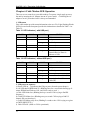
Table 4. RF Downstream Specification
PARAMETER
Center Frequency
VALUE
91 MHz to 857 MHz +/- 30 kHz
NOTES
Level Range
-15 dBmV to +15 dBmV
One Channel
Symbol Rate
64QAM
256QAM
Bandwidth
5.056941 Msym/sec (30 Mbps)
5.360537 Msym/sec (43 Mbps)
6 MHz
Total Input Power
<30 dBmV
Input Impedance
75 Ohms
Input Return Loss
>6 dB
88 MHz to 860 MHz
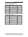
Table 5. RF Upstream Specification
PARAMETER
Frequency
VALUE
5 MHz to 42 MHz
NOTES
Edge to Edge
Level Range
+8 to +58 dBmV
+8 to +55 dBmV
QPSK and 16QAM
QPSK
16QAM
Modulation
Symbol Rate
320K,640K,1280K,2560K,5120Kbps QPSK
640K,1280K,2560K,5120K,10240Kbps 16QAM
Bandwidth
200K, 400K, 800K, 1600K,
and 3200 KHz
75 Ohms
Output Impedance
Output Return Loss >6 dB
At Edges
5 MHz to 42 MHz
13
DOCSIS 1.0/ 1.1 Equivalent Cable Modem
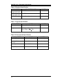
Table 6. Electrical Specification
PARAMETER
MEASURED VALUE
Power Adapter output 11.4 VDC
voltage lower limit
Power Adapter output 12.6 VDC
voltage upper limit
Current consumption 560 mA Normal mode
NOTES
Normal mode
Table 7. Physical Specification
PARAMETER
Size
VALUE
181mm (H) x 143mm (L) x 36 mm (W)
Weight
Net Weight: 450g + 30g
Gross Weight: 900g + 60g
NOTES
Table 8. Environmental Specification
PARAMETER
Operating Temperature
VALUE
0 ° C to +40 ° C
Operating Relative
Humidity
Operating Altitude
10% to 90%
Storage Temperature
-10 ° C to +60 ° C
14
-100 to +7,000 feet
NOTES
Non-condensing
DOCSIS 1.0/ 1.1 Equivalent Cable Modem
Appendix B: Questions and Answers
Section 1: Troubleshooting Modem LED Problems
Troubleshooting the modem portion of this Cable Modem begins with observing the
front panel lights (also called LEDs - light emitting diodes). The pattern of these lights
indicates the status of the modem. Interpreting the pattern correctly can indicate
whether the modem is functioning properly or not. If there is a problem, the lights
provide clues as to what the problem might be. The Cable Modem does not require any
routine maintenance. If you cannot identify and correct a fault using these
troubleshooting procedures, please contact your cable television (CATV) Internet
Service Provider (ISP).
Question 1: The Power Light Is Off
Answer:
The normal state for this light is solid red. If the Power light is off, then the modem
is not receiving power. Possible Solutions:
1. Check to make sure the power cable is firmly plugged into both the cable modem
and the electrical outlet. Try unplugging, then reconnecting the cable at each end.
2. Check that the wall outlet is working. Test it by using a light or some other device in
the suspect outlet.
3. If the power light remains off, the external power supply or the power cord is
probably defective. Contact the supplier of the Cable Modem for assistance.
Question 2: The Cable Light Is Off
Answer:
The normal state for this light is solid green. If the Cable Light Is Off, then the
modem is not detecting the downstream radio frequency (RF) signal provided by the
cable network. This could be caused by any of the following:
• Radio frequency noise in the home
• Damaged cable
• Bad or loose cable connections
• Unterminated connections
• Problem with the cable on the street
• Problem in the cable network
Possible Solutions:
1. Disconnect and then reconnect the power. This will automatically reset the
modem.
2. Wait at least 4 minutes.
3. If the Cable light is still off, then there could be a problem with the cable wiring.
Check all cables between the modem and the ground terminal outside the house.
Unplug the power again, then plug it back in as before.
4. If the Cable light is still off, there might be a problem with the cable network or the
modem. Contact your cable provider.
15
DOCSIS 1.0/ 1.1 Equivalent Cable Modem
Question 3: The LAN Light Is Off
Answer:
If the LAN light is on, the Cable Modem's Ethernet port is connected to the computer
correctly. If the modem is having problems transferring data, check the Cable light,
as described in the above Cable Light subsection, to determine the state of the modem.
If the LAN light is off, the modem is not detecting the Ethernet network interface card.
Possible Solutions:
1. Make sure the cable between your computer’s Ethernet card and the modem is
securely fastened at each end.
2. There may be a green “carrier detect” light on the back of the Ethernet card. It
should be a steady green. If the cable is securely connected, then the Ethernet card
may have loosened from its socket. Open up the computer and make sure the card is
firmly seated in place.
3. If you have plugged a hub into the port, you need to use a crossover Ethernet cable
instead of a straight through cable.
4. Try replacing the cable between the modem and the Ethernet card.
5. If the problem persists, it could indicate a problem with the Ethernet card or the
modem. Contact the manufacturer of the Ethernet card or your cable provider.
Question 4: The RX Light Is Off
Answer:
The RX Light flickering On and Off indicates that the cable network is successfully
receiving data. If the RX light is off, then the cable network is not receiving data
from the modem.
If the cable network is having problems transferring data, check the Cable light as
described above.
Question 5: The TX Light Is Off
Answer:
The TX Light flickering On and Off indicates that the cable network is successfully
transmitting data. If the cable network is having problems transferring data, check
the Cable light, as described above.
If the TX light is off, then the cable network is not transmitting data to the modem. If
the modem is having problems transferring data, check the Cable light, as described
above.
Question 6: All LEDs look right, but I still cannot access the Internet
Answer:
If the Power, Cable LEDs, and LAN LED are lighted, the cable modem is operating
properly. Try shutting down the computer and then turning it on. This causes the
computer to re-establish communications with your cable service provider’s computer.
Power cycle the cable modem by removing the power adapter from its outlet and then
plugging it back into the outlet. Then try reconnecting to your cable service provider.
Verify that you have installed TCP/IP properly, and that the TCP/IP parameters
provided by your cable service provider are correct for your computer.
If you are using a cable line splitter so that you can connect the cable modem and a
television at the same time, try removing the splitter and reconnecting the cables so
that the cable modem is connected directly to the cable wall jack. Then try
reconnecting to your cable service provider.
16
DOCSIS 1.0/ 1.1 Equivalent Cable Modem
Section 2: Troubleshooting Network Problems
If you have been referred to this section from one of the paragraphs above then there is
a possible problem with your cable network. Contact your CATV ISP to check if the
network is functioning correctly. If the network is functioning correctly then there is
likely a problem with your cable modem. Contact your CATV ISP.
Section 3: Troubleshooting User Application Problems
Question 7: If CATV ISP provides one IP address only, how do I switch CPE?
Answer: Possible Solutions:
You may switch CPE in two ways:
1. On same computer, switch between Ethernet and USB interfaces
2. Switch from A computer to B computer
No matter how you switch CPE, please be noted that this cable modem is following
with DOCSIS specification definition. The DOCSIS rules if changing to the other
CPE device, the cable modem learned original CPE information can't be replaced.
You have to do restart (power cycle) or reset the cable modem and follow with the
Ethernet or USB installation to set up your cable modem.
Question 8: How to Offer Multiple Users to Operate on One Cable Modem
Answer: Possible Solutions:
1. Connecting to 2 Computer Devices through Ethernet and USB Interfaces:
This cable modem provides you the feature for Ethernet and USB interfaces to
operate on 2 different computer devices simultaneously. However, you have to
obtain additional IP addresses from your CATV ISP.
2. Connecting to More Than one Computer Devices through Ethernet Interface
using an External Hub:
The Cable Modem can simultaneously support up to 15 host devices. The actual
number may be limited by your CATV ISP. If your CATV ISP allows you to use
multiple IP addresses, you may attach multiple computers or other IP devices using
an external hub.
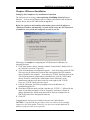
Question 9: How to check if the USB Installation is completed?
Answer:
Using USB with the Windows 98 or Windows Me Operating System
17
DOCSIS 1.0/ 1.1 Equivalent Cable Modem
Click Network on Control Panel, make sure USB Cable Modem is installed
NOTE: If you have no TCP/IP protocol, press Add, highlight Protocol and press Add.
Then next step is to highlight Microsoft and TCP/IP, and then press OK to complete the
adding TCP/IP protocol process.
2. Click TCP/IP -> Conexant USB Cable Modem
3. Click Properties
18
DOCSIS 1.0/ 1.1 Equivalent Cable Modem
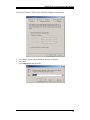
4. Click the IP Address TAB, choose Obtain an IP address automatically
5. For Windows 98/Me, On the Windows Desktop, click Start.
6. Select Run.
7. Type winipcfg.exe and Click OK
19
DOCSIS 1.0/ 1.1 Equivalent Cable Modem
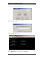
8. Select your adapter name- USB Cable Modem
9. Click Renew. If you don’t receive an IP address
10. Type command and click ok
11. Type ipconfig and press Enter
12. Type ipconfig /renew_all if you don’t receive an IP address
20
DOCSIS 1.0/ 1.1 Equivalent Cable Modem
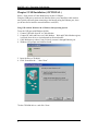
Using USB with the Windows 2000 or Windows XP Operating System
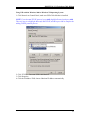
1. Click Network on Control Panel, make sure USB Cable Modem is installed
NOTE: If you have no TCP/IP protocol, press Add, highlight Protocol and press Add.
Then next step is to highlight Microsoft and TCP/IP, and then press OK to complete the
adding TCP/IP protocol process.
2. Click TCP/IP -> Conexant USB Cable Modem
3. Click Properties
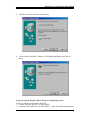
4. Click the IP Address TAB, choose Obtain an IP address automatically
21
DOCSIS 1.0/ 1.1 Equivalent Cable Modem
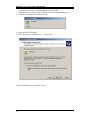
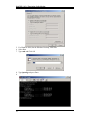
5. For Windows 2000, On the Windows Desktop, click Start.
6. Select Run.
7. Type cmd and Click OK
8. Type ipconfig and press Enter
9.
22
DOCSIS 1.0/ 1.1 Equivalent Cable Modem
10. Type ipconfig /renew if you don’t receive an IP address
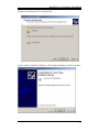
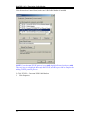
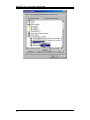
Question 10: I could not install USB driver well anyway.
Answer:
In case you do not install USB driver correctly. Please go to DEVICE MANAGER and
if you see an yellow exclamation mark follow by “CMX300v2 “ , as shown in the
picture below this content. Select “ USB Composite Device “ and click the right button
of your mouse, select “ Remove “. Now you may exit the DEVICE MANAGER.
Please run Cable Modem Wizard again and install USB Driver.
23
DOCSIS 1.0/ 1.1 Equivalent Cable Modem
24
DOCSIS 1.0/ 1.1 Equivalent Cable Modem
Appendix C: Glossary
Bandwidth
Amount of data that can be transmitted per time.
Baseline Privacy Interface
The baseline privacy interface (BPI) provides cable modem users with data privacy
across the cable network by encrypting data traffic between user's cable modem and
CMTS.
BER
Bit Error Rate
Browser
A computer program that lets users access and display information from the World
Wide Web. Two of the most commonly used browsers are Netscape Navigator and
Microsoft Internet Explorer.
CATV
A cable television network system.
CCCM
CPE Controlled Cable Modems
CMTS (Cable Modem Termination System)
The Cable Modem Termination System (CMTS) is the major component of the
headend. It interfaces to the cable network, the backbone data network, and several
support systems. The CMTS also controls the configuration, registration, and media
access of all the cable modems under its control, and determines who gets to transmit
when, and for how long.
Coaxial Cable
Coaxial cable ("coax") allows wide bandwidth transmission over long distances. The
coax cable is composed of an inner wire surrounded by an outer conductive shield.
CPE
Customer premises equipment
Decryption
The conversion of a coded (encrypted) signal to its original form, by means of an
algorithm.
Demodulation
The process of recovering, at the receiver, an original transmitted signal that has been
modulated.
Demodulator
A/D, demodulation, error correction, MPEG synchronization
25
DOCSIS 1.0/ 1.1 Equivalent Cable Modem
DHCP
Protocol used to automatically assign various network settings, most notably IP
addresses
DHCP Client Capabilities
The Dynamic Host Configuration Protocol (DHCP) provides centralized management
of the Transmission Control Protocol/Internet Protocol (TCP/IP) client configurations,
including the IP address, gateway address, Domain Name Server (DNS) address and
more. The DHCP Client enables the Office Cable Modem to acquire TCP/IP settings
(such as the IP address, gateway address, and DNS address) from the ISP. This is ideal
when one TCP/IP address is provided by the ISP and this address may change from
time to time, as is the case with many cable modem Internet accounts.
DNS
Domain Name System. Automated system used to translate computer names into IP
addresses. A DNS server is used to look up a name and provide its address to the
requesting computer.
DOCSIS
Data Over Cable Service Interface Specification. A standard that defines interface
requirements for cable modems involved in high-speed data distribution over cable
television networks.
Downstream
Indicates the direction of flow of a data stream from the cable headend to the user’s
computer.
Duplex Tuner
A tuner that processes both upstream and downstream signals.
Encryption
The scrambling of a signal by means of an algorithm, to prevent unauthorised
monitoring of the message.
Ethernet
A network technology that employs a bus topology in which all computers attach to a
single cable similar to the stops on a bus line. The Ethernet technology is an accepted
worldwide standard whose characteristics are defined by the IEEE 802.3 standards
committee.
F connector
A type of coaxial connector, labeled RF on the rear of the cable modem that connects
the modem to the cable system.
Firewall
A software or hardware system that prevents unauthorized outside access, theft,
deletion, or modification of information stored on a local network. Typically, this
unauthorized access would be via an organization's Internet connection.
26
DOCSIS 1.0/ 1.1 Equivalent Cable Modem
Headend
The aggregation point in a CATV plant where control equipment is located. The CMTS
resides here, as does video broadcast and monitoring equipment.
HFC (Hybrid Fibre/Coax)
A cable system where the cables closest to the Headend are fiber technology, and the
cables dropped into individual homes are coaxial. Between these two ends, the signal
is converted from fiber to coaxial. The coaxial cable then runs through the branches of
the network and is finally dropped into the home.
Hub
Electronic device that accepts data from a sending computer and delivers it to the
appropriate destination. Many networks are shaped like a wheel with different
computers attached at the ends of the wheel’s spokes; the hub is the center of the wheel
ICMP
Part of the TCP/IP protocol used for network diagnosis.
IEEE 802.3
IEEE is the Institute for Electrical and Electronic Engineers. 802.3 refers to the
specifications of the Ethernet protocol.
ISP
Internet Service Provider. A commercial organization that provides access to the
Internet for its subscribers
IP
Internet Protocol. IP is a standard that defines the format of packets of information sent
over the Internet and the mechanism for routing each packet to its destination. IP is the
network portion of TCP/IP, the most commonly used protocol suite for the Internet.
IP Address
A unique, 32-bit address assigned to every device in a network. An IP address is
composed of a network address and a host address. Each network is assigned an
address by a government agency, and each company administrator assigns an address
to each host computer.
Latenacy/(Lag)
Excessive response time. Time between sending a request to a server (e.g. web page)
and receiving the response.
LED
Light-Emitting Diode. A semiconductor device that emits light when voltage is applied
between its terminals. LEDs are used on the cable modems as front panel lights.
MAC Address
The physical address of the Media Access Control device.
27
DOCSIS 1.0/ 1.1 Equivalent Cable Modem
MAC (Media Access Control)
Media Access Control (MAC) is the protocol governing access to the network. The
MAC device is located between receive and transmit paths. Among its functions are
the controlling of ranging, the assignment of frequencies, and the allocation of time
slots.
MCNS
Multimedia Cable Network System
Modulation
A controlled variation of any property of a carrier wave for transferring data.
Modulator
Encoding, modulation, frequency conversion, D/A conversion, etc.
MSO
Multiple Service Operator
NAT
Network Address Translation, technique used to share a single IP address to provide
internet access to a LAN.
Network Interface Card
A Network Interface Card (NIC) is a plug-in circuit board installed in an expansion
slot of the computer. The NIC (also called an Ethernet card) takes parallel data from
the computer, converts it to serial data, packets it, and sends it out over a 10BaseT
cable.
OS (Operating System)
The basic software that allows application programs to access a computer’s hardware
resources.
Packet loss
Number of data packets that are lost in transmission.
Ping
Program to measure network latency.
QAM (Quadrature Amplitude Modulation)
QAM is a method of combining two amplitude-modulated signals into a single channel,
thereby doubling the effective bandwidth. QAM is used with pulse amplitude
modulation (PAM) in digital systems, especially in wireless applications.
In a QAM signal, there are two carriers, each having the same frequency but differing
in phase by 90 degrees (one quarter of a cycle, from which the term quadrature arises).
One signal is called the I signal, and the other is called the Q signal. Mathematically,
one of the signals can be represented by a sin wave, and the other by a cosine wave.
The two modulated carriers are combined at the source for transmission. At the
destination, the carriers are separated, the data is extracted from each, and then the data
is combined into the original modulating information.
28
DOCSIS 1.0/ 1.1 Equivalent Cable Modem
QoS
Quality of Service. Often used to indicate a certain service level guaranty.
QPSK
Quadrature Phase Shift Keying
QPSK is a digital frequency modulation technique used for sending data over coaxial
cable networks. Since it's both easy to implement and fairly resistant to noise, QPSK is
used primarily for sending data from the cable subscriber upstream to the Internet.
RF (Radio Frequency)
A range of the electromagnetic spectrum. Signals in this frequency range can be
transmitted through the air or through a wire. High-speed cable modems use RF
technology to send and receive signals over the cable television network.
RJ45
The type of connector used with twisted-pair Ethernet wiring.
SNMP
Simple Network Management Protocol
TCP
Transmission Control Protocol. This standard provides transmission control for
applications to ensure reliable delivery of data despite changing network conditions,
such as congestion or failure of a segment of the network. TCP is the transport layer
portion of TCP/IP, the most commonly used protocol suite for the Internet.
TCP/IP
Transmission Control Protocol/Internet Protocol. The most commonly used protocol
suite for the Internet; refers to two of its most import protocols, TCP and IP.
TFTP
Trivial File Transfer Protocol
ToD
Time of Date
Tuner
Converts TV channels to a fixed lower frequency (6 ~ 40 MHz)
Two-Way Cable Modem Access
Cable access that allows data to flow in both the upstream and downstream directions.
UDP
Part of the TCP/IP protocol used to exchange data over the internet
Upstream
Indicates the direction of the flow of a data stream from the user’s computer to the
network headend.
29
DOCSIS 1.0/ 1.1 Equivalent Cable Modem
USB (Universal Serial Bus)
The Universal Serial Bus (USB) replaces many different types of serial and parallel
port connectors with one standard plug and port combination.
10BaseT
An unshielded, twisted pair cable with RJ-45 connectors used with an Ethernet LAN.
"10" indicates the speed (10 Mbps), "Base" refers to baseband technology, and "T"
means twisted pair cable.
64QAM
64-State Quadrature Amplitude Modulation
This digital frequency modulation technique is primarily used for sending data
downstream over a coaxial cable network. 64QAM is very efficient, supporting up to
28-mbps peak transfer rates over a single 6-MHz channel. But 64QAM's susceptibility
to interfering signals makes it ill suited to noisy upstream transmissions (from the
cable subscriber to the Internet).
30