1
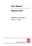
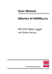
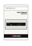
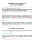
User Manual
ASeries A440
Interface Converter
RS-232 ó RS-422
The interfacing specialists
A440 User Manual
Version 2.02
March 1999
COPYRIGHTS
All rights reserved. This document may not, in whole or part, be copied, photocopied,
reproduced, translated, or reduced to any electronic medium or machine readable form without
the express permission in writing from Alfatron Pty Ltd.
Copyright 1999 © Alfatron Pty Ltd
DISCLAIMER
Alfatron Pty Ltd has made every attempt to ensure that the information contained in this
document is accurate and complete. Alfatron Pty Ltd makes no representation or warranties of
merchantability or fitness for any particular purpose. Alfatron Pty Ltd reserves the right to make
changes to this document at any time, without notice. Therefore, Alfatron Pty Ltd assumes no
liability for damages incurred directly or indirectly from errors, omissions or discrepancies with
the hardware and the manual.
TRADEMARKS
All Company and Product names are trademarks of the Company or Manufacturer respectively.
WARRANTY
Alfatron warrants its products against defects in materials and workmanship for a period of one
year from receipt by the customer. All warranty is carried out on a return to depot basis unless
an alternative warranty coverage has been arranged.
WARRANTY EXCLUSIONS
The above warranty shall not apply to defects resulting from improper or inadequate
maintenance by the customer, unauthorised modifications or misues, operation outside the
environmental specifications for the product, damage due to power surges, lightening strikes or
any other phenomenon outside normal operational specifications.
Alfatron Pty Ltd ACN: 005 410 819
P.O. Box 4161
Unit 9/36 New St.
Ringwood VIC 3134
AUSTRALIA
Web Site: www.alfatron.com.au
A440 User Manual
1.0
PRODUCT DESCRIPTION
The ASeries A440 allows RS-232 serial devices to communicate with RS-422
devices. As well as transferring data, this unit also provides one pair of
handshaking lines, either DTR/DSR or CTS/RTS, for the control of the data
flow.
The following illustration shows the location of all the connectors, indicators
and switches of the A440:
RS-232
Serial Port
DCE/DTE
Selection
RS-232 ’RD’
LED (Green)
RS-422
Termination
Resistor
Selection
Power
LED (Yellow)
RS-422
Serial Port
Power Jack
RS422 ’RD’
LED (Green)
Figure 1 - A440 viewed from all sides
Features
l Switch select the RS-232 port as either DCE or DTE.
l Switch select Termination Resistors on the RS-422 port.
l Transient protection using Transorbs.
l LED indicators for Data Activity and Power.
l Quality nickel plated metal case will withstand the most rugged application.
Using A440s as RS-232 Line Extenders
A pair of A440s may be used to achieve connection of RS-232 devices over
an extended distance. The A440s are connected via their RS-422 ports to
take advantage of the greater data transfer distances available using the RS422 Serial protocol. Please refer to Section 6.6 for cable details.
1
A440 User Manual
2.0 INSTALLATION
The A440 does not require configuration but it does provide the convenience
of being able to select the RS-232 port as either DCE or DTE. Before
connecting power to the unit please make sure that the RS-232 and RS-422
cables are securely connected to the A440 and associated devices.
Sections 5 and 6 contain details on cabling, along with some examples of
typical uses for the A440.
After all cables have been connected and secured, insert the power plug into
the jack socket and turn the power ON. The A440 is now ready for use.
2.1
Function of LED indicators
The 'RS-232' LED indicator monitors the activity on the 'RD' pin of the RS-232
serial port. The LED will flash each time data is received by the A440 on this
line.
The 'RS-422' LED indicator monitors the activity on the 'RD+' and 'RD-' data
pair pins of the RS-422 serial port. The LED will flash each time data is received
by the A440 on these data pair lines.
The 'RS-232' and 'RS-422' LED indicators will not operate at any other time.
The 'Power' LED will remain ON when the A440 has power.
2.2
Termination Resistors for RS-422
The A440 provides switch selectable termination resistors for the Receive
Data (RD) and Data Set Ready (DSR) incoming lines. Termination resistors
are only required when the cable length exceeds 50 metres.
The A440 provides termination resistors on the 'receiver' side only. The reason
for this is that, in most environments, cable lengths greater than 300 metres
require termination only on the 'receiver' side.
The location of termination resistor switch is at the side of the A440 as shown
in Figure 1. The selection of the termination resistors is as follows:
2
6ZLWFK
5HFHLYH'DWD5'
6ZLWFK
'DWD6HW5HDG\'65
2))
7HUPLQDWLRQ5HVLVWRU
127$&7,9(
7HUPLQDWLRQ5HVLVWRU
127$&7,9(
21
7HUPLQDWLRQ5HVLVWRU
$&7,9(
7HUPLQDWLRQ5HVLVWRU
$&7,9(
A440 User Manual
3.0
RS-232 SERIAL PORT PINOUT
The RS-232 Serial Port of the A440 is factory configuired as DCE.
Pin
Status and Usage
1
2
3
4
5
6
7
8
20
Used
- (Ground)
Input / Output- (Data)
Output / Input- (Data)
Not used
- (Pulled High 4K7)
Not used
- (Pulled High 4K7)
Output / Input- (Handshaking)
Used
- (Ground)
Not used
- (Pulled High 4K7)
Input / Output- (Handshaking)
Note:
Set for DCE Set for DTE
FG
RD
TD
CTS
RTS
DTR
SG
DCD
DSR
FG
TD
RD
RTS
CTS
DSR
SG
DCD
DTR
Pins 4, 5, 6, 8 and 20 are pulled to the correct levels to allow a PC serial port to
operate under most conditions without any additional loopback connections.
The Factory Default RS-232
Serial switch setting is DCE
as shown here:
4.0
RS-422A PORT PINOUT
Pin
Status and Usage
Signal
Description
Used - (Ground)
Used - (Ground)
FG
SG
Frame Ground
Signal ground
13
25
Output- (Data)
Output- (Data)
TD+
TD-
Transmit Data +
Transmit Data -
12
24
Input - (Data)
Input - (Data)
RD+
RD-
Receive Data +
Receive Data -
11
23
Output- (Handshaking) DTR+
Output- (Handshaking) DTR-
Data terminal ready +
Data terminal ready -
9
21
Input - (Handshaking) DSR+
Input - (Handshaking) DSR-
Data Set Ready +
Data Set Ready -
1
7
3
A440 User Manual
4.1
Transient Protection on RS-422 Port
Power surges, or electrical transient voltages, can be induced into cabling by
nearby lightening strikes, electric motors, switches and the operation of heavy
industrial equipment, to name a few. The use of long cables, as with RS-422
connections, increases the exposure to transient voltages.
In an unprotected converter, a transient of the correct magnitude can destroy
the RS-422 transceiver chip on the RS-422 port. However, it is also possible
for certain transients to pass through a converter and therefore damage any
RS-232 attached equipment at the other end.
By using High Speed Transient Voltage Suppressors on the RS-422 port, the
A440 absorbs much of the transient energy on data lines and helps clamp
these surge voltages to a safe level, thereby protecting itself and other
connected equipment from the common damage due to transients.
Transient voltage suppressor diodes are used on each RS-422 line. Each
diode has a response time of less than 1 ps with power dissipation of 600Watts
for 1 ms and a steady state power dissipation rating of 5Watts.
5.0 CABLE REQUIREMENTS
Alfatron recommends the use of shielded cable with its products. It reduces
Electro Magnetic Radiation and improves noise immunity. This helps minimise
interference to other equipment and improves communication reliability.
5.1
Cable Construction
The recommended shielded cable construction is as follows:
5.2
l
Solder the shield (surrounding cable wires) to the Frame Ground (FG) pin. If FG is
not available, use Signal Ground (SG) but in this case always use a separate wire
for ground which is connected at both ends.
l
Make sure that the shield is connected at both ends of the cable.
Cable Diagrams
Cable diagrams represent cable shield in the following manner:
This shows the cable shield soldered to FG at both ends of the cable and
shows the shield running the full length of the cable. Please note that the
shield is treated as a totally separate wire.
4
A440 User Manual
6.0
CABLE EXAMPLES
6.1
RS-422 Connection to Other RS-422 Devices
Shield
A440 Cable End
(DB-25 Male)
6.2
FG
SG
TD+
TDRD+
RDDTR+
DTRDSR+
DSR-
FG
SG
RD+
RDTD+
TDDSR+
DSRDTR+
DTR-
1
7
13
25
12
24
11
23
9
21
User Device
Cable End
RS-232 Connection to a PC with DB-25 Serial Connector
Shield
A440 Cable End
DCE
(DB-25 Male)
6.3
FG
RD
TD
CTS
RTS
DTR
SG
DCD
DSR
1
2
3
4
5
6
7
8
20
1
2
3
4
5
6
7
8
20
FG
TD
RD
RTS
CTS
DSR
SG
DCD
DTR
PC Cable End
DTE
(DB-25 Female)
RS-232 Connection to a PC with DB-9 Serial Connector
Shield
A440 Cable End
DCE
(DB-25 Male)
RD
TD
CTS
RTS
DTR
SG
DCD
DSR
2
3
4
5
6
7
8
20
3
2
7
8
6
5
1
4
TD
RD
RTS
CTS
DSR
SG
DCD
DTR
PC Cable End
(DB-9 Female)
5
A440 User Manual
6.4
RS-232 connection to other RS-232 Devices
Shield
FG
RD
TD
CTS
RTS
DTR
SG
DCD
DSR
A440 Cable End
DCE
(DB-25 Male)
6.5
1
2
3
4
5
6
7
8
20
FG
TD
RD
RTS
CTS
DSR
SG
DCD
DTR
User Device
Cable End
Using RTS / CTS Handshaking with the A440
The following diagram shows the A440 connected to a 'Host' RS-232 serial
device and a 'Remote' RS-422 serial device. In this example the 'Host' is a
'DTE' device so the A440 is selected as 'DCE' on the RS-232 port.
RS-232
Host
Connection
(D B -25) DTE
FG
TD
RD
RTS
CTS
SG
DCD
6.6
1
2
3
4
5
7
8
RS-422
A440
Connection
Remote
DCE
1
2
3
20
6
7
8
FG
RD
TD
DSR
DTR
SG
DCD
FG
SG
TD+
TDRD+
RDDTR+
DTRDSR+
DSR-
1
7
13
25
12
24
11
23
9
21
FG
SG
RD+
RDTD+
TDCTS+
CTSRTS+
RTS-
A440s used as RS-232 LINE EXTENDERS
A common use for the A440 is to use them in pairs to provide a reliable line
extension setup for RS-232 devices. The following three diagrams show how
two A440s may be used as RS-232 line extenders while adopting different
RS-232 handshaking methods.
6
A440 User Manual
6.6.1 Example showing RTS / CTS handshaking
The following diagram shows A440s being used as line extenders in an RS232 RTS/CTS Handshaking situation. In this example the 'Host' is 'DTE' and
the 'Remote' is 'DCE', which allows the use of the same 'straight through'
cable for each RS-232 connection to the A440.
Host
RS-232
Connect
1
2
3
4
5
7
8
1
2
3
20
6
7
8
FG
RD
TD
DSR
DTR
SG
DCD
RS-232
A440
Connect
Connect
DTE
DCE
DTE (DB-25)
FG
TD
RD
RTS
CTS
SG
DCD
RS-422
A440
FG
SG
TD+
TDRD+
RDDTR+
DTRDSR+
DSR-
1
7
13
25
12
24
11
23
9
21
1
7
12
24
13
25
9
21
11
23
FG
SG
RD+
RDTD+
TDDSR+
DSRDTR+
DTR-
Remote
DCE
(DB-25)
FG
1
TD
2
RD
3
DTR 20
DSR 6
SG
7
DCD 8
1
2
3
4
5
7
8
FG
RD
TD
CTS
RTS
SG
DCD
6.6.2 Example showing DTR / DSR handshaking
The following diagram shows A440s being used as line extenders in an RS232 DTR/DSR Handshaking situation. In this example the 'Host' is 'DTE' and
the 'Remote' is 'DCE', which allows the use of the same 'straight through'
cable for each RS-232 connection to the A440.
Host
DTE
FG
1
TD
2
RD
3
DSR 6
SG
7
DCD 8
DTR 20
RS-232
Connect
RS-422
A440
A440
Connect
DCE
(DB-25)
1
2
3
6
7
8
20
FG
RD
TD
DTR
SG
DCD
DSR
RS-232
Connect
DTE
FG
SG
TD+
TDRD+
RDDTR+
DTRDSR+
DSR-
1
7
13
25
12
24
11
23
9
21
1
7
12
24
13
25
9
21
11
23
FG
SG
RD+
RDTD+
TDDSR+
DSRDTR+
DTR-
FG
1
TD
2
RD
3
DSR 6
SG
7
DCD 8
DTR 20
Remote
(DB-25)
DCE
1
2
3
6
7
8
20
FG
RD
TD
DTR
SG
DCD
DSR
7
A440 User Manual
6.6.3 Example showing Xon / Xoff handshaking
The following diagram shows A440s being used as line extenders in an RS232 Xon/Xoff Software Handshaking situation. In this example the 'Host' is
'DTE' and the 'Remote' is 'DCE', which allows the use of the same 'straight
through' cable for each RS-232 connection to the A440.
Host
RS-232
DTE (DB-25)
FG
TD
RD
SG
6.7
1
2
3
7
RS-422
A440
Connect
A440
Connect
DCE
1
2
3
7
FG
RD
TD
SG
RS-232
Connect
DTE
FG
SG
TD+
TDRD+
RD-
1
7
13
25
12
24
1
7
12
24
13
25
FG
SG
RD+
RDTD+
TD-
FG
TD
RD
SG
Remote
(DB-25)
1
2
3
7
DCE
1
2
3
7
FG
RD
TD
SG
Unused Handshake Lines
Please note that many RS-232 devices still require their handshaking lines to
be set to the correct levels, even if Xon/Xoff software handshaking is used.
When in doubt about any particular RS-232 device simply connect all the
lines to the A440 RS-232 port as it will pull those lines to the correct level for
operation.
8
A440 User Manual
7.0
SPECIFICATIONS
RS-232C Port:
Asynchronous RS-232C/V.24
Select as DCE or DTE
DB-25 female connector
Speed capability dependant on cable
length up to 64k bits per second
RS-422A Port:
RS-422A
DB-25 female connector
120W Termination Resistor Selection for the
incoming handshaking lines 'RD' & 'DSR'.
Transient Protection:
(RS-422 Port only)
Handshaking:
LED Indicators:
Power Supply:
Transient Voltage Suppression Diode
Surge handling capacity 600W per wire @ 1ps
Response time per diode < 1ms
Steady state power dissipation rate of 5W
Xon / Xoff Software Handshaking
DTR / DSR Hardware Handshaking
Receive Data - RS-232 (Green)
Receive Data - RS-422 (Green)
Power
(Yellow)
9V (200mA) DC Power Adapter
Reverse polarity protection
Plug jack - 5.5mm outer/2.5mm inner diameter
Outer Negative:
Dimensions:
Weight:
Operating Temperature:
Stroage Temperature:
84mm x 58mm x 23mm
160 grams
10° to 35° C
0° to 45° C
All specifications subject to change without notice
9
N42
DECLARATION OF CONFORMITY
according to the European Commissions EMC Directive 89/336/EEC
We,
of,
Name of Manufacturer:
Address of Manufacturer:
Australian Company Number:
ALFATRON PTY. LTD
UNIT 9, 36 NEW ST.
RINGWOOD VIC 3134
AUSTRALIA
ACN: 005 410 819
declare under sole responsibility that the product:
Product Name:
ASeries RS-232 to RS-422
Interface Converter
Model Number:
A440
to which this declaration relates is in conformity with the following standards:
CISPR-22 / EN 55022 class B
IEC 801-2 / prEN55024-2
IEC 801-3 / prEN55024-3
IEC 801-4 / prEN55024-4
EMI from Information Technology Equipment (ITE)
Electro Static Discharge Immunity
Radiated RF Immunity
Electrical Fast Transients Immunity