1
ACCESSORY BOARDS
Zigbee User Manual
Join the Technical Community Today!
http://www.pantechsolutions.net
Contents
Introduction ............................................................................................ 3
Packages ............................................................................................... 3
Technical or Customer Support ............................................................ 3
1. Introduction ....................................................................................... 4
Supported Modules .............................................................................. 4
Base Board Specifications..................................................................... 4
General Block Diagram ......................................................................... 5
2. Zigbee Modules ( Xbee | XBee –PRO) ................................................ 5
Performance......................................................................................... 6
Networking........................................................................................... 6
Zigbee Specifications ............................................................................ 6
Pin Details of XBee | Xbee – PRO Modules .......................................... 8
3. XBee Board Details............................................................................. 8
Power Supply ....................................................................................... 8
RESET.................................................................................................... 8
I/O & Power LEDs ................................................................................. 9
Serial Port ............................................................................................. 9
RSSI Indicators ...................................................................................... 9
4. X-CTU Software ................................................................................ 10
Installation ......................................................................................... 10
Setup .................................................................................................. 10
Serial Communication Software ......................................................... 11
Join the Technical Community Today!
http://www.pantechsolutions.net
Introduction
Zigbee Kit, is proposed to smooth the progress of
developing
and
debugging
of
various
designs
encompassing of Zigbee Based applications with MCU.
Packages
EVB-Zigbee Kit (XBee)
Serial Port Cable
CD contains
o Software
o Example Programs | User Manual
Technical or Customer Support
Post your questions
:
Pantech forum
:
www.pantechsolutions.net/forum
Website
:
www.pantechsolutions.net
Join the Technical Community Today!
http://www.pantechsolutions.net
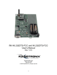
1. Introduction
This Evaluation board supports Digi/Maxstream Low cost
Zigbee modules. It has on-board RSSI indicators and Data flow
indicators, facility to connect directly to the microcontroller or PC
through RS232 interface. The XBee 802.15.4 (formerly Series 1) OEM RF
module is an IEEE 802.15.4 compliant solution that satisfies the unique
needs of low-power wireless sensor networks. It is easy-to-use, requires
minimal power and provides reliable delivery of critical data between
devices.
No
configuration
is
necessary
for
out-of-box
RF
communications. Advanced configurations can be implemented using
simple AT commands.
Supported Modules
• Xbee
• Xbee-Pro
Base Board Specifications
• On-Board Voltage Regulator
• Data Flow Indicators (Rx/Tx/Assoc)
• Power ON status Indication LED.
• RSSI Level Indicators
• DB9 Connector for PC or MCU Interface.
Join the Technical Community Today!
http://www.pantechsolutions.net
General Block Diagram
+5V
Adaptor PWR
+3V3
REG
MAX 3232
ADC IN
DB9
Connector
I/O
LED
Indicators
Rx
XBee
RSSI
RSSI
Indicators
RESET
2.
Zigbee Modules ( Xbee | XBee –PRO)
The XBee 802.15.4 (formerly Series 1) OEM RF module is an IEEE
802.15.4 compliant solution that satisfies the unique needs of lowcost, low-power wireless sensor networks. It is easy-to-use,
requires minimal power and provides reliable delivery of critical
data between devices. Its small form factor saves valuable board
space.
No configuration is necessary for out-of-box RF communications.
The XBee module’s default configuration supports a wide range of
data system applications. Advanced configurations can be
implemented using simple AT commands.
Join the Technical Community Today!
http://www.pantechsolutions.net
Performance
Transmit power output: 1mW (0 dBm) | Indoor/Urban
range: Up to 100 ft (30 m)
Outdoor/RF line-of-sight range: Up to 300 ft (100 m)
RF data rate: 250 Kbps |Interface data rate: Up to 115.2 Kbps
Operating frequency: 2.4 GHz |Receiver sensitivity: -92 dBm
Networking
Spread Spectrum type: DSSS (Direct Sequence Spread
Spectrum)
Networking topology: Peer-to-peer, point-to-point, and
point-to-multipoint
Error handling: Retries & acknowledgements
Filtration options: PAN ID, channel and addresses
Channel capacity: 16 Direct Sequence Channels (software
selectable)
Addressing: 65,000 network addresses available for each
channel
Encryption: 128-bit AES
Zigbee Specifications
Features:
Interoperability with ZigBee devices from other vendors*
No configuration needed for out-of-the-box RF
communications
Join the Technical Community Today!
http://www.pantechsolutions.net
ZigBee mesh networking protocol
Self-healing and discovery for network stability
Platform
XBee® ZB
XBee-PRO® ZB
Performance
RF Data Rate
250 Kbps
Indoor/Urban Range
133 ft (40 m)
300 ft. (90 m) / Int‘l 200 ft (60 m)
Outdoor/RF Line-of-Sight
Range
400 ft (120 m)
1 mile (1600 m)/ Int’l 2500 ft (750 m)
1.25 mW (+1 dBm) / 2 mW (+3 dBm) boost
mode
50 mW (+17 dBm) / Int’l 10 mW (+10
dBm)
-96 dBm in boost mode
-102 dBm
Transmit Power
Receiver Sensitivity (1% PER)
Features
Serial Data Interface
Configuration Method
3.3V CMOS UART
API or AT commands, local or over-the-air
Frequency Band
Interference Immunity
2.4 GHz
DSSS (Direct Sequence Spread Spectrum)
Serial Data Rate
1200 bps - 1 Mbps
ADC Inputs
(4) 10-bit ADC inputs
Digital I/O
10
Antenna Options
Chip, Wire Whip, U.FL, RPSMA
Networking & Security
Encryption
128-bit AES
Reliable Packet Delivery
IDs and Channels
Retries/Acknowledgments
PAN ID, 64-bit IEEE MAC, 16 channels
PAN ID, 64-bit IEEE MAC, 14 channels
2.1 - 3.6VDC
3.0 - 3.4VDC
Transmit Current
35 mA / 45 mA boost mode @ 3.3VDC
294 mA (@ 3.3V) / Int’l 170 mA (@
3.3V)
Receive Current
38 mA / 40 mA boost mode @ 3.3VDC
45 mA @ 3.3VDC
<1 uA @ 25º C
<10 uA @ 25º C
Power Requirements
Supply Voltage
Power-Down Current
Join the Technical Community Today!
http://www.pantechsolutions.net
Pin Details of XBee | Xbee – PRO Modules
3. XBee Board Details
Power Supply
The external power can be DC source only, with a voltage (+5V/,1A
output) at 230V AC input. The LM1117 Fixed +3.3V positive
regulator is used to provides power to the Zigbee Modules and
other peripherals. Separate slide switch is provided to power the
board (ON/OFF).
RESET
Join the Technical Community Today!
http://www.pantechsolutions.net
The Reset Switch is used to reset (re-boot) the RF module. This
switch only applies when using the configuration tabs of
MaxStream’s X-CTU Software
I/O & Power LEDs
LEDs indicate RF module activity as follows:
Yellow (top LED) = Serial Data Out (to host)
Green (middle) = Serial Data In (from host)
Red (bottom) = Power/Association Indicator (Refer to the D5
(DIO5 Configuration) parameter)
Serial Port
Standard female DB-9 (RS-232) connector.
Note : Male – Female 9-pin Straight cable (Rx-Rx | Tx-Tx)
RSSI Indicators
RSSI LEDs indicate the amount of fade margin present in an active
wireless link. Fade margin is defined as the difference between the
incoming signal strength and the module's receiver sensitivity.
3 LEDs ON = Very Strong Signal (> 30 dB fade margin)
2 LEDs ON = Strong Signal (> 20 dB fade margin)
1 LED ON = Moderate Signal (> 10 dB fade margin)
0 LED ON = Weak Signal (< 10 dB fade margin)
Join the Technical Community Today!
http://www.pantechsolutions.net
4. X-CTU Software
X-CTU is a MaxStream-provided software program used to
interface with and configure Max-Stream RF Modules. The
software application is organized into the following four tabs:
• PC Settings tab - Setup PC serial ports for interfacing with an RF
module
• Range Test tab - Test the RF module's range and monitor packets
sent and received
• Terminal tab - Set and read RF module parameters using AT
Commands
• Modem Configuration tab - Set and read RF module parameters
Installation
Double-click the "setup_X-CTU.exe" file and follow prompts of the
installation screens. This file is
located in the 'software' folder of the MaxStream CD and also
under the 'Downloads' section of the following web page:
www.maxstream.net/support/downloads.php
Setup
To use the X-CTU software, a module assembly (An RF module
mounted to an interface Board)
Join the Technical Community Today!
http://www.pantechsolutions.net
must be connected to a serial port of a PC.
NOTE: Failure to enter AT Command Mode is most commonly due
to baud rate mismatch. The
interface data rate and parity settings of the serial port ("PC
Settings" tab) must match those of
the module (BD (Baud Rate) and NB (Parity) parameters
respectively).
Serial Communication Software
A terminal program is built into the X-CTU Software. Other
terminal programs such as "HyperTerminal" can also be used to configure modules and monitor
communications. When issuing AT Commands through a terminal
program interface, use the following syntax:
Figure . Syntax for sending AT Commands
Join the Technical Community Today!
http://www.pantechsolutions.net
NOTE:
To read a parameter value stored in a register, leave the
parameter field blank.
The example above issues the DL (Destination Address Low)
command to change destination address of the module to "0x1F".
To save the new value to the module’s non-volatile memory, issue
WR (Write) command after modifying parameters.
Join the Technical Community Today!
http://www.pantechsolutions.net
Did you enjoy the read?
Pantech solutions creates information packed
technical documents like this one every month. And our
website is a rich and trusted resource used by a vibrant
online community of more than 1, 00,000 members from
organization of all shapes and sizes.
Join the Technical Community Today!
http://www.pantechsolutions.net
What do we sell?
Our products range from Various
Microcontroller development boards, DSP Boards,
FPGA/CPLD boards, Communication Kits, Power
electronics, Basic electronics, Robotics, Sensors,
Electronic components and much more . Our goal is
to make finding the parts and information you need
easier and affordable so you can create awesome
projects and training from Basic to Cutting edge
technology.
Join the Technical Community Today!
http://www.pantechsolutions.net