1
MEGATORQUE® MOTOR SYSTEM
User’s Manual
(ESA35/ESAC5 Driver Unit System)
NSK Ltd.
Document Number: C20137-01
Limited Warranty
NSK Ltd. warrants its products to be free from defects in material and/or workmanship which NSK
Ltd. is notified of in writing within, which comes first, one (1) year of shipment or 2 400 total
operation hours. NSK Ltd.., at its option, and with transportation charges prepaid by the claimant,
will repair or replace any product which has been proved to the satisfaction of NSK Ltd. to have a
defect in material and/or workmanship.
This warranty is the sole and exclusive remedy available, and under no circumstances shall NSK
Ltd. be liable for any consequential damages, loss of profits and/or personal injury as a result of
claim arising under this limited warranty. NSK Ltd. makes no other warranty express or implied,
and disclaims any warranties for fitness for a particular purpose or merchantability.
Copyright 2003 by NSK Ltd. Tokyo, Japan
All rights reserved.
No part of this publication may be reproduced in any
form or by any means without permission in writing
from NSK Ltd.
NSK Ltd. reserves the right to make changes to any
products herein to improve reliability, function or design
without prior notice and without any obligation.
NSK Ltd. does not assume any liability arising out of the
application or use of any product described herein;
neither does it convey any license under its present
patent nor the rights of others.
Patents issued and patents pending.
“MEGATORQUE” is a registered trademark of NSK Ltd. in
Japan, and that of NSK Precision America, Inc. in the United
States of America.
In order to use the Megatorque Motor System properly,
observe the following notes.
1. Matters to be attended to use the Driver Unit of the Megatorque Motor System
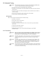
------ For prolonged use of the Driver Unit -----1 Temperature
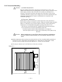
Keep the ambient temperature of the Driver Unit within 0 to 50°C. You cannot put the Driver Unit in an
atmosphere over 50°C. Keep a clearance of 100 mm in upper and lower sides of the Driver Unit when it is
installed in an enclosure. If heat is build up on upper side of the Driver Unit, provide the ventilation
openings on the top, or equip an air cool unit to take the heat out of the Driver Unit.
(Measures against contamination are required for the ventilation openings.)
2 Protection against contamination and water
Put the Driver Unit in an enclosure that complies with IP54 or better protection code. Protect the Driver
Unit from oil-mist, cutting oil, metal chips, and paint fume etc. Otherwise it may result in failures of
electric circuits of the Driver Unit.
(IP code is specified in IEC standard. This is to classify the protection level of enclosures from solid
contamination and water.)
3 Wiring / Ground
Refer to the User's Manual for proper wiring.
Take appropriate measures not to contaminate the Driver Unit when wiring or installing it.
4 Storing
Store the Driver Unit in a place at where it is not exposed to rain, water and harmful gas or liquid.
Store the Driver Unit in a place at where it is not exposed to direct sun light. Keep the ambient
temperature and humidity as specified.
2. Matters to be attended to use the Motor of the Megatorque Motor System
------ For prolonged use of the Megatorque Motor -----1 Dustproof and Waterproof of the Motor
Make sure that how your Motor is graded for dust-proof and/or waterproof. You cannot use the
Megatorque Motor in the environment where chemicals or paint fumes exist.
◊ Standard Megatorque Motors (RS, AS, BS, JS, SS and YSB Series)
They are not made to dustproof or waterproof specification. (Equivalent to IP20, IP30 or IP40)
You may not expose them to humid or oily environment.
◊ Simple waterproof Motor (RW Series)
Some part of the Motor is not completely waterproofed. Confirm what part is not waterproofed
with the specification document, and then take appropriate measures to the part against water
and dust if necessary. For a long time use of the Motor, we recommend making sure of its aging
trend of the Motor with the periodical insulation test approximately once in every half year. You
cannot use this type of Motors unless you take the measures against the environment with water
or oil.
◊ Waterproof Motor (RZ series: IP65 equivalent)
Use this type of Motor when continually splash water or oil on it. Provide air purge when you
use the Motor in IP66 or equivalent condition. Be sure to supply a dry air. The user shall take
the measures against dust. For a long term use, check the Motor for its aging by insulation test
(approximately once in every half year).
2 Use condition
The allowable moment load and axial load differ with Motor size. Reconfirm that the using conditions are
in the specified limits of the Motor.
An excessive offset load or heavy load will cause permanent deflection of the rotor and the bearing
abnormality. Be sure not to give excessive impact to the Motor that is caused by external interference in
transit or at installation.
The flatness of the Motor mounting surface shall be 0.02 mm or less.
3 Periodical check
Puncture of the Motor and shorting or breakage of cable may occur depending on using condition and
environment. If the Motor is left in such conditions, it cannot exhibit its capability 100 % and will lead to
a problem of the Driver Unit. We recommend conducting the periodical check in order to detect the
problem.
3. Before concluding that the system is faulty, check the matters again.
1 Alarm arises
Did you take proper action to the alarm? Check the action for an alarm described in the manual again.
2 Power does not turn on. Indication lamp does not turn on.
Check voltage of main and control power sources by a tester if the voltage is in the specification described
in the User’s manual.
3 The Motor does not function.
Is rotation of the Motor smooth when it is turned manually with power off? Any stickiness in motion?
Does the rotation axis have any axial play?
(Never disassemble the Motor.)
Are the control Inputs and Outputs functioning properly?
→ Monitor status of SVON, RUN and IPOS signals by I/O command through handy terminal.
→ Check if the voltage of input signal, and 24 V power source are stable with an oscilloscope, etc.
4 Uncontrollable Driver Unit
Compare the current setting of parameters with the original setting at the installation. Does the PA data
(unique to individual Motor) change?
5 The Motor vibrates. Positioning is inaccurate. Alarm of software thermal arises frequently.
Are servo parameters VG, VI, PG, FP and NP adjusted?
Do you fasten the fixing bolts of load and the Motor mounting securely? Check and fasten them tightly if
necessary.
Connect FG terminal of the Driver Unit to one point grounding. Ground the Motor and the Driver Unit
respectively. (Refer to User’s Manual for wiring.)
Is any external interference with rotation in Servo lock state? (It leads the Motor to overheat if external
force is applied to it in servo lock state.)
6 Breaker trip occurs frequently.
When the system recovers by remaking the power, take the following action.
◊ We recommend installing a delay type breaker for a measure against breaker trip.
4. Others
Combination of the Motor and the Driver Unit shall conform to the specification.
Be sure to write down the setting of parameters.
Never modify the cable set.
Lock the connectors securely, and check for loose fixing screw(s).
Please keep expendable parts, and backup parts in stock. (Fuses, Motor, Driver Unit, and Cable set for
replace)
Use alcohol for cleaning. Do not apply thinner.
(Blank Page)
Contents
1. Introduction ------------------------------------1-1
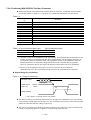
2.9.4.1. Genreral Input Signals------------------- 2-27
2.9.4.2. Pulse Train Command------------------- 2-27
2.9.4.3. General Output Signal ------------------- 2-28
2.9.4.4. Alarm Output ------------------------------- 2-28
2.9.4.5. Position Feedback Signal Output ----- 2-29
2.9.4.6. Analog Command Input ----------------- 2-29
2.9.4.7. Analog Monitor ---------------------------- 2-30
2.9.5. Wiring Connectors (CN2 and CN5)---------- 2-31
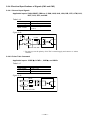
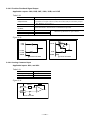
2.9.5.1. Example of Velocity Control Mode --- 2-31
2.9.5.2. Example of Position Control Mode --- 2-32
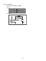
2.9.5.3. Application of Mechanical Brake ------ 2-33
2.10. CN3: Resolver Cable Connector ------------------ 2-36
2.10.1. Pin-Out (CN3) ----------------------------------- 2-36
2.10.2. Signal List ---------------------------------------- 2-36
2.11. CN4: Motor Connector ------------------------------- 2-37
2.11.1. CN4 Pin-Out ------------------------------------- 2-37
2.11.2. CN4 Signal List --------------------------------- 2-37
2.12 Terminal Block for Power Supply------------------- 2-38
2.12.1. Terminal List ------------------------------------- 2-38
2.12.2. Wiring Diagram --------------------------------- 2-38
2.13. Jumper Pin ---------------------------------------------- 2-39
2.13.1. JP1 (Selection of øZ out put signal format
-------------------------------------------------------- 2-39
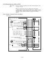
2.14. Wiring Diagram----------------------------------------- 2-40
1.1. Notes to Users ---------------------------------------------1-1
1.1.1. Notes for Safety ------------------------------------1-1
1.1.2. Interchangeability of Motor and Driver Unit -1-4
1.2. Terminology ------------------------------------------------1-3
2. Specification-----------------------------------2-1
2.1. System Configuration ------------------------------------2-1
2.2. Coding for Reference Number -----------------------2-2
2.2.1. System Reference Number ---------------------2-2
2.2.2. RS Type Megatorque Motor---------------------2-2
2.2.3. ESA Driver Unit for RS Type Motor -----------2-2
2.2.4. Cable Set for RS Type Megatorque Motor --2-3
2.2.5. Handy Terminal ------------------------------------2-3
2.3. Name of Parts----------------------------------------------2-4
2.3.1. RS Type Motor -------------------------------------2-4
2.3.2. AS Type Motor--------------------------------------2-4
2.3.3. ESA Driver Unit-------------------------------------2-5
2.3.4. Handy Terminal ------------------------------------2-6
2.4.Standard Configuration of Motor and Driver Unit --2-7
2.4.1.Combination of ESA Driver Unit and Motor --2-7
2.4.1.1. Standard Motor------------------------------2-7
2.4.1.2. Motor Equipped With Absolute Position
Sensor -----------------------------------------2-7
2.4.1.3. Cable Set -------------------------------------2-7
2.4.2. Handy Terminal (For inputting paramters and
Programs) -------------------------------------------2-8
2.5. Motor Specifications--------------------------------------2-9
2.5.1. Standard Motor -------------------------------------2-9
2.5.2. Motor With Absolute Position Sensor---------2-9
2.5.3. How to Calculate Axial Load and Moment
Load------------------------------------------------- 2-10
2.6. External Dimensios ------------------------------------- 2-11
2.6.1. External External Dimensions of Standard
Motor------------------------------------------------ 2-11
2.6.2. External Dimensions of Motor Equipeed With
Absolute Position Sensor ---------------------- 2-13
2.6.3. Dimensions of Driver Unit---------------------- 2-15
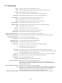
2.7. General Spcifications of Driver Unit
2.7.1. General Specifications-------------------------- 2-18
2.7.2. Functional Specifications ---------------------- 2-19
2.8. RS-232C Interface Specifications------------------- 2-19
2.8.1. CN1 RS-232C Serial Comunication Connector
------------------------------------------------------- 2-19
2.8.1.1. CN1 Pin-out -------------------------------- 2-19
2.8.1.2. CN1 Signal List---------------------------- 2-20
2.8.1.3. Sample Wiring Diagram (CN1) -------- 2-21
2.9. CN2 and CN5 Control I/O Signal Connector ----- 2-22
2.9.1. Pin-out (CN2 and CN5) ----------------------- 2-23
2.9.2. Signal Name and Function (CN2 and CN5)----------------------------------------------------------- 2-24
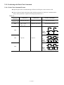
2.9.3. Setting the Porality of the input Ports
(Normally open or closed contacts) --------- 2-26
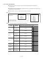
2.9.4. Electrical Specifications of Signals
(CN2 and CN5)----------------------------------- 2-27
3. Unpacking • Installation • Wiring ---------3-1
3.1. Unpacking -------------------------------------------------3.1.1. Receiving Check ---------------------------------3.1.2. Combination of Motor and Driver Unit ------3.2.Installation -------------------------------------------------3.2.1. Motor ------------------------------------------------3.2.1.1. Mounting Motor----------------------------3.2.1.2. attaching Load (Work) to Motor -------3.2.1.3. Confirmation of Load Inertia------------3.3.Wiring -------------------------------------------------------3.3.1. Motor Wiring---------------------------------------3.3.2. Connecting Main Power ------------------------3.3.3. Cnnector Wiring ----------------------------------3.3.4. Ground Connection------------------------------3.4. Turning on the Main Power ---------------------------3.4.1. Precautions ----------------------------------------3.4.2. Indication of Power on --------------------------3.4.3. Power on and Servo ON ------------------------
3-1
3-1
3-1
3-3
3-3
3-3
3-3
3-3
3-5
3-5
3-6
3-7
3-7
3-8
3-8
3-8
3-9
4. Handy Terminal Communication ---------4-1
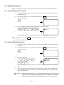
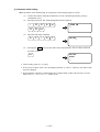
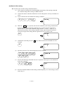
4.1. Setting Prameters ---------------------------------------- 4-3
4.1.1. Setting Without the Password ----------------- 4-3
4.1.2. Setting With the Password---------------------- 4-3
—i—
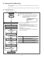
5. Tuning and Trial Running ------------------5-1
5.1. Tuning Sequece -------------------------------------------5-1
5.2. Automatic Tuning -----------------------------------------5-2
5.2.1. Precautions ----------------------------------------5-3
5.2.2. Initialization of Servo Parameters--------------5-5
5.2.3. Execution of Automatic Tuning
(Tuning Level 1)------------------------------------5-8
5.2.4. Trial Running (Tuning Level 1) -----------------5-7
5.2.5. Minor Servo Adjustment (Tuning Level 2) ---5-9
5.3. Manual Tuning ----------------------------------------- 5-11
5.3.1. Precautions for Manual Tuning--------------- 5-11
5.3.2. Adjustment of Velocity Loop
Proportinal Gain (VG) -------------------------- 5-11
5.3.3. Adjustment of Veolocity Loop
Integration Frequency-------------------------- 5-13
5.4. Setting Filters (Tuning Level 2) ---------------------- 5-15
6. Operational Function ------------------------6-1
6.1. General Operation and Function ----------------------6-1
6.1.1. Servo “ON” ------------------------------------------6-1
6.1.2. Emergency Stop -----------------------------------6-3
6.1.3. Interruption of Positioning With STP Input---6-4
6.1.4. Making Pulse Train Position Command or
Analog Command Ineffective -------------------6-4
6.1.5. Clearing Position Error Counter ----------------6-5
6.1.6. ntegration OFF -------------------------------------6-6
6.1.7. Lowerin Velocity Loop Proportional Gain ----6-6
6.1.8. Over Travel Limit-----------------------------------6-7
6.1.8.1. Hardware Over Travel Limit--------------6-7
6.1.8.2. Software Over Travel Limit ---------------6-8
6.1.9. Alarm Output ----------------------------------------6-9
6.1.10. Brake Output ------------------------------------ 6-10
6.1.10.1 Control of Brake -------------------------- 6-11
6.1.11 In-Oosition Output ------------------------------ 6-12
6.1.11.1. Output Signal Fomat ------------------- 6-13
6.1.11.2. Parameter IN----------------------------- 6-14
6.1.11.3. Parameter IS ----------------------------- 6-14
6.1.11.4. IPOS Output in Special Occasion -- 6-14
6.1.12. Definition of Home Position------------------ 6-15
6.1.13. Completion of Home Return/Detection of
Home Position ------------------------------------ 6-15
6.1.13.1. Signal Output Mode -------------------- 6-15
6.1.14. Velocity Report---------------------------------- 6-16
6.1.15. Target Proximity/In Target ------------------- 6-17
6.1.16. Positin Feedback Signal---------------------- 6-20
6.1.17. Monitor Functions ------------------------------ 6-21
6.1.17.1. Analog Velocity Monitor --------------- 6-22
6.1.17.2. Monitoring Control Input/Output Signals
------------------------------------------------- 623
6.1.17.3. Monitoring Pulse Train Input Counter
------------------------------------------------ 6-25
6.1.17.4.Monitoring Current Position ----------- 6-26
6.1.17.5.Monitoring Position Error Counter
(RS-232C Communication Monitor) - 6-26
6.1.17.6. Monitoring Motor Velocity------------- 6-26
6.1.17.7. Monitoring Torque Command and
Sftware Thermal Loading --------------- 6-27
6.1.17.8. Monitoring State of Automatic Gain
Switching ---------------------------------- 6-27
6.1.17.9. Monitoring Paraemter setting -------- 6-28
6.1.17.10. Monitoring Alarm Identification----- 6-29
6.1.17.11. Monitoring Contents of Channel--- 6-29
— ii —
6.1.17.12 Monitoring Cahnging State of Contol
I/O and History of Program Execution
------------------------------------------------- 6-30
6.1.17.13. Monitoring Analog Command ------ 6-32
6.2. Functions for More Advanced Operation---------- 6-37
6.2.1. Incremental Position Scale
(Withouf Absolute Positioning Function) --- 6-37
6.2.1.1. Resolution of Position Scale ----------- 6-37
6.2.1.2. Dirction of Position Scale --------------- 6-38
6.2.1.3. Type of Position Scale------------------- 6-39
6.2.1.4. Resetting Home Position---------------- 6-42
6.2.2. Absolute Position Scale
(Absolute Positioning Function)-------------- 6-43
6.2.2.1. Direction of Position Scale-------------- 6-43
6.2.2.2. Resolution of Position Scale ----------- 8-44
6.2.2.3. Offsetting Position Data ----------------- 6-46
6.2.2.4. Monitoring Positoin Data ---------------- 6-45
6.2.2.5. setting User Home Position ------------ 6-46
6.2.3. Digital Filter ---------------------------------------- 6-46
6.2.4. Feed Forward Compensation: FF------------ 6-47
6.2.5. Integraion Limiter: ILV -------------------------- 6-48
6.2.6. Dead Band: DBP --------------------------------- 6-49
6.2.7. Automatic Gain Swithcing---------------------- 6-50
6.2.8. Acceleration Profiling---------------------------- 6-51
6.3. RS-232C Communication ----------------------------- 6-56
6.3.1. Specifcations of Communication ------------- 6-56
6.3.2. Communication Procedure -------------------- 6-56
6.3.2.1. Turning on Power ------------------------- 6-56
6.3.2.2. Command Entry --------------------------- 6-57
6.3.2.3. Password ----------------------------------- 6-58
6.3.2.4. Cancelling Command -------------------- 6-59
6.3.2.5. Error ------------------------------------------ 6-60
6.3.2.6. monitoring Command -------------------- 6-62
6.3.3. Communication with Personal Computor -- 6-64
6.3.3.1. Set-up of Hyper Terminal --------------- 6-64
6.3.3.2. Store Parameter of ESA35 Driver Unit
------------------------------------------------- 6-65
6.3.3.3. Transmit Stored parameters to ESA35
Driver Unit ---------------------------------- 6-65
6.3.4. Daisy Chain Communication ------------------ 6-66
6.3.4.1.Procedure to Set Daisy Chain
Communication------------------------------ 6-66
6.3.4.2. Initial Setting ------------------------------- 6-67
6.3.4.3. Interfacing----------------------------------- 6-67
6.3.4.4. Power on ------------------------------------ 6-69
6.3.4.5. Operation ----------------------------------- 6-70
7. Operation -------------------------------------7-1
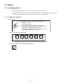
7-1. Preparation -------------------------------------------------7-1
7.1.1. Wiring Check----------------------------------------7-1
7.1.2. Operation Procedure------------------------------7-1
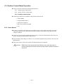
7-2. Position Control Mode Operation ---------------------7-3
7.2.1.Home Reurn ----------------------------------------7-3
7.2.1.1. List of Parameters Related to Home
Return ------------------------------------------ 7.6
7.2.1.2. Adjusting Home Limit Sensor Position
and Home Ofset Data -----------------------7-8
7.2.1.3. Example of Setting Home Return
Operation -------------------------------------7-9
7.2.1.4. Operation Mode of Home Return----- 7-10
7.2.2. Positioning with Programmable Indexer --- 7-13
7.2.2.1. Internal Program Channel selection - 7-14
7.2.3. Positioning With Pulse Train Command --- 7-16
7.2.3.1.Pulse Train Command Format --------- 7-15
7.2.3.2. Pulse Train Resolution ------------------ 7-16
7.2.3.3. Pulse Train Input Timing---------------- 7-18
7.2.4. Positioning With RS-232C Position Command
------------------------------------------------------- 7-19
7.2.5. Jog Operation------------------------------------- 7-20
7.3. Positioning With analog Velocity Command ----- 7-21
7.3.1. Positioning with RS-232C Command ------- 7-21
7.3.2. Pisitioning With Analog Velocity Command
------------------------------------------------------- 7-22
7.3.2.1. Dead Band Set to Command Voltage
------------------------------------------------ 7-23
7.3.2.2 Offsetting analog Command------------ 7-23
7.3.3. Functioning With Analog Torque Command
------------------------------------------------------- 7-26
7.4. Posioning With Torque Control Mode-------------- 7-27
7.4.1. Operation by RS-232C Position Command
------------------------------------------------ 7-27
7.4.2. Positioning With Analog torque Command
------------------------------------------------ 7-28
7-4.2.1. Dead Band Set to Command Voltage
------------------------------------------------ 7-29
7.4.2.2. Offsetting Analog Command----------- 7-29
8. Programming----------------------------------8-1
8.1. Command and Parameter for Condition Setting
-----------------------------------------------------------------8-1
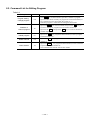
8.2. Command List for Editing Program
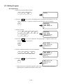
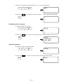
8.3. Editing Program -------------------------------------------8-8
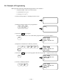
8.4. Example of Programming -------------------------------8-8
9. Glossary of Command and Parameter
9.1. Glossary of Command and Parameter --------------9-1
AB : I/O Polarity --------------------------------------9-1
AC : Analog Command Mode---------------------9-1
AD : Absolute Positioning, Degree --------------9-2
AE : Automatic Tuning Error, Alarm Type -----9-2
AF : Analog Command Offset --------------------9-3
AG : Analog Command Gain----------------------9-3
AL : Acceleration Limiter---------------------------9-3
AN : Axis Number------------------------------------8-4
AO : Absolute Position Scale Offset-------------9-5
AR : Absolute Positioning, Resolver ------------9-5
— iii —
AS
AT
AX
AZ
BM
CA
CC
CD
CH
CI
CL
CM
CO
CR
CS
CS
CV
CX
CY
CZ
DB
DC
DI
DP
EC
EP
FC
FD
FF
FO
FP
FR
FS
FW
FZ
: Read out Daisy Chain Status-------------- 9-6
: Automatic Tuning----------------------------- 9-6
: Axis Select ------------------------------------- 9-6
: Absolute Zero Position Set----------------- 9-6
: Backspace Mode ----------------------------- 9-6
: Channel Acceleration------------------------ 9-7
: Clear Channel --------------------------------- 9-7
: Delete Channel ------------------------------- 9-7
: Channel Select-------------------------------- 9-8
: Insert Channel--------------------------------- 9-8
: Clear Alarm ------------------------------------ 9-8
: Communication Mode ----------------------- 9-9
: Position Error Counter Over Limit -------- 9-9
: Circular Resolution--------------------------- 9-9
: Acceleration Pattern Select
(common setting)------------------------------ 9-10
: Acceleration Pattern Select (set to a
channel of Programmable Indexer.)------ 9-10
: Channel Velocity----------------------------- 9-11
: Setting CS Function ------------------------ 9-11
: Criterion to function CS -------------------- 9-11
: Check Actual Acceleration ---------------- 9-12
: Dead Band ------------------------------------ 9-12
: Digital RS-232C Command --------------- 9-13
: Direction Inversion -------------------------- 9-13
: Debugger for Program --------------------- 9-13
: End of Command Message--------------- 9-14
: Excessive Position Error, Alarm Type-- 9-14
: Friction ----------------------------------------- 9-14
: Feed Back Direction Mode---------------- 9-15
: Feed Forward Gain ------------------------- 9-15
: Low-pass Filter Off Velocity--------------- 9-15
: Low-pass Filter, Primary------------------- 9-16
: Feed Back Signal Resolution
(Factory use only)----------------------------- 9-16
: Low-pass Filter, Secondary--------------- 9-16
: FIN Width-------------------------------------- 9-17
: Feedback Phase Z Configuration ------- 9-17
GP : Gain Switching Point:GP ---------------- 9-18
GT
HA
HD
HI
HO
HS
HT
HV
HW
HZ
ID
ILV
IM
IN
: Switching Gain Timer----------------------- 9-18
: Home Return Acceleration ---------------- 9-18
: Home Return Direction--------------------- 9-19
: Home In-position ---------------------------- 9-19
: Home Offset ---------------------------------- 9-19
: Home Return Start -------------------------- 9-20
: Hardware Travel Limit Over, Alarm Type
----------------------------------------------------- 9-20
: Home Return Velocity ---------------------- 9-20
: HOME Signal Holding Time -------------- 9-21
: Home Return Near-Zero Velocity ------- 9-21
: Incremental Positioning, Degree -------- 9-22
: Integration Limit------------------------------ 9-22
: IOFF Mode ------------------------------------ 9-23
: In-position ------------------------------------- 9-23
IO : Input/Output Monitor------------------------ 9-23
IR : Incremental Positioning, Resolver ------ 9-24
IS : In-position Stability Counter -------------- 9-24
JA : Jog Acceleration----------------------------- 9-25
JP : Jump-------------------------------------------- 9-25
JV : Jog Velocity----------------------------------- 9-25
LG : Lower Gain------------------------------------ 9-25
LO : Load Inertia ----------------------------------- 9-26
LR : Low Torque Ripple-------------------------- 9-26
MA : Move Acceleration -------------------------- 9-26
MD : Move Deceleration -------------------------- 9-27
MI : Read Motor ID ------------------------------- 9-27
MM : Multi-line Mode------------------------------- 9-27
MN : Monitor Select-------------------------------- 9-28
MO Motor Off--------------------------------------- 9-28
MS : Motor Stop ------------------------------------ 9-28
MT : Motor Torque (Factory use only) -------- 9-29
MV : Move Velocity -------------------------------- 9-29
NA : Near Position A ------------------------------ 9-29
NB : Near Position B ------------------------------ 9-29
NMA: Near A Output Mode ----------------------- 9-30
NMB: Near B Output Mode ----------------------- 9-30
NP : Notch Filter, Primary------------------------ 9-30
NS : Notch Filter, Secondary-------------------- 9-31
NW : Chattering Preventive Timer-------------- 9-31
OE : Sequence Option Edit---------------------- 9-31
OG : Origin Set-------------------------------------- 9-32
OL : Overload Limit (Factory use only)------- 9-32
OP : Forced Output Port Primary/Extended- 9-32
OR : Criterion, Overrun Alarm ------------------ 9-33
OS : Origin Setting Mode ------------------------ 9-33
OTP : Over Travel Limit Switch Position ------- 9-33
OTM: Over Travel Limit Switch Position ------- 9-33
OU : Origin Undefined, Alarm Type ----------- 9-34
PA : Phase Adjust (Factory use only) -------- 9-34
PC : Pulse Command----------------------------- 9-34
PE : Program Error, Alarm Type --------------- 9-35
PG : Position Gain --------------------------------- 9-35
PH : Program Home Return--------------------- 9-35
PS : Position Scale Select----------------------- 9-36
RA : Read Analog Command ------------------- 9-36
RC : Rated Current (Factory use only) ------- 9-36
RI : Rotor Inertia (Factory use only)---------- 9-37
RO : ABS/INC (Factory use only) -------------- 9-37
RP : Read Pulse Train Command ------------- 9-37
RR : Resolver Resolution
(Factory use only) ------------------------- 9-37
SB : Criterion, SPD Signal Output------------- 9-38
SE : Serial Error------------------------------------ 9-38
SG : Servo Gain ------------------------------------ 9-38
SI : System Initialization ------------------------ 9-39
SL :Set Control Mode ---------------------------- 9-39
SO : SPD Output Mode--------------------------- 9-40
SP : Start Program -------------------------------- 9-40
ST : Speed stability Timer ----------------------- 9-40
SV
TA
TC
TE
TG
TI
TL
TO
: Servo On -------------------------------------- 9-40
: Tell Alarm Status ---------------------------- 9-41
: Tell Channel Program ---------------------- 9-42
: Tell Position Error Counter---------------- 9-42
: Tell Gain Switching ------------------------- 9-42
: Timer ------------------------------------------- 9-43
: Torque Limit Rate --------------------------- 9-43
: Software Travel Limit Over, Alarm Type
----------------------------------------------------- 9-43
TP : Tell Position----------------------------------- 9-44
TR : Tell RDC Position Data -------------------- 9-44
TS : Tell Settings----------------------------------- 9-45
TT : Tell Torque & Thermal --------------------- 9-45
TV : Tell Velocity ----------------------------------- 9-46
VG : Velocity Gain --------------------------------- 9-46
VGL : Velocity Gain, Lower------------------------ 9-46
VI : Velocity Integrator Frequency ------------ 9-47
VIL : Velocity Integrator Frequency, Lower -- 9-47
VM : Velocity Integrator Mode------------------- 9-47
VO : Velocity Error Over Limit------------------- 9-48
VW : Velocity Error Over Limit Width ---------- 9-48
WD : Write Data to EEPROM-------------------- 9-48
WM : Write Mode to EEPROM------------------- 9-49
ZAS : Start Point of Zone A ----------------------- 9-49
ZAE : End Point of Zone A ------------------------ 9-49
ZBS : Start Point of Zone B ----------------------- 9-49
ZBE : End Point of Zone B ------------------------ 9-49
ZP : Position damping (Factory use only) --- 9-50
ZV : Velocity damping (Factory use only) --- 9-50
9.2.. Parameter List------------------------------------------- 9-51
10. Maintenance ------------------------------- 10-1
— iv —
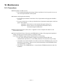
10.1. Precautions --------------------------------------------- 10-1
10.2. Periodical Check --------------------------------------- 10-2
10.2.1. Motor ---------------------------------------------- 10-2
10.2.2. Driver Unit and Cable Set -------------------- 10-2
10.3. Periodical Replcement of Parts -------------------- 10-3
10.3.1. Motor ---------------------------------------------- 10-3
10.3.2. Driver Unit -------------------------------------- 10-3
10.4. Storing ---------------------------------------------------- 10-3
10.5. Warranty Period and Coverage -------------------- 10.4
10.5.1. Warranty Period -------------------------------- 10-4
10.5.2. Limited Warranty ------------------------------- 10-4
10.5.3. Immunities---------------------------------------- 10-4
10.5.4. Service Fee -------------------------------------- 10-4
11. Alarm ---------------------------------------- 11-1
11.1. identifying alarm --------------------------------------- 11-1
11.1.1. LED alarm Indication -------------------------- 11-1
11.1.2. Using TA Command --------------------------- 11-3
11.2. Alarm List------------------------------------------------ 11-4
11.2.1. normal Satete ----------------------------------- 11-4
11.2.1.1 Alarm State-------------------------------- 11-5
11.2.2. Alarms Related to Power Amplifier -------- 11-6
11.2.2.1. Heat Sinc Overheat or Regeneration
Resistor Overheat ------------------------ 11-6
11.2.2.2. Abnormal Main AC Line Voltage ---- 11-7
11.2.2.3. Over Current ----------------------------- 11-8
11.2.2.4. Control AC Line Under Voltage ----- 11-9
11.2.3. Alarms Related to Motor---------------------- 11-9
11.2.3.1. Resolver Circuit Error ------------------ 11-9
11.2.3.2. Absolute Position Error (For Driver Unit
equipped with absolute position sensor)
---------------------------------------------- 11-10
11.2.3.3. Software Thermal Sensor----------- 11-10
11.2.3.4. Velocity Error Over ------------------- 11-11
11.2.3.5. Home Position Undefined----------- 11-11
11.2.4. Alarms Related to Control------------------ 11-12
11.2.4.1. Memory Error -------------------------- 11-12
11.2.4.2. EEPROM Error ------------------------ 11-12
11.2.4.3. System Error --------------------------- 11-12
11.2.4.4. CPU Error ------------------------------- 11-13
11.2.4.5. Interface Error ------------------------- 11-13
11.2.4.6. analog Command Error ------------- 11-13
11.2.4.7. Excessive Position Error ------------ 11-14
11.2.4.8. Software Over Travel Limit --------- 11-15
11.2.4.9. Hardware Over Travel Limit -------- 11-16
11.2.4.10. Emergency Stop --------------------- 11-16
11.2.4.11. Program Error ------------------------ 11-17
11.2.4.12. Automatic Tuning Error ------------ 11-17
11.2.4.13. RS-232C Error ----------------------- 11-18
11.2.4.14. CPU Error ----------------------------- 11-18
11.2.5. Readout of Alarm With TA Command -- 11-19
11.2.6. Histry of alarm--------------------------------- 11-20
11.2.6.1. Indication of Alarm History---------- 11-20
11.2.6.2. Clear history of Alarm---------------- 11-20
11.2.7. Interchangeable alarm Setting With Other
Driver Unit Series ------------------------------ 11-21
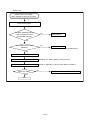
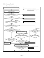
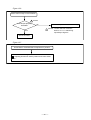
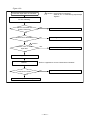
12. Troubleshooting--------------------------- 12-1
12.1. Identifying Problem ----------------------------------- 12-1
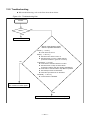
12.2. Troubleshooting---------------------------------------- 12-2
12.2.1. Power Troublle---------------------------------- 12-3
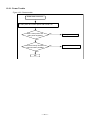
12.2.2. Motor Trouble ----------------------------------- 12-4
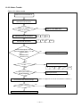
12.2.3. Command Trouble ----------------------------- 12-6
12.2.4. Terminal ---------------------------------------- 12-10
Appendix
Appendix 1: Monitoring Input/Output signal ------------- A-1
Appendix 2: How to Check Motor Condition ------------ A-7
Appendix 3: Initilization of Driver Unit--------------------A-11
Appendix 4: How to Replace ESA35 or ESAC5 Driver
Unit-----------------------------------------------A-14
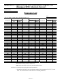
Appendix 5: ESA35 Driver Unit Parameter / Program List
----------------------------------------------------A-20
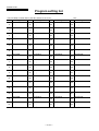
Appendix 6: ESAC5 Driver Unit Parameter/Program List
(Equipped With Absolute Sensor)--------A-22
—v—
(Blank Page)
— vi —
1. Introduction
This manual describes the interface, function, and operation of the Megatorque Motor System
with ESA35 or ESAC5 Driver Unit.
Before operating the Megatorque Motor System, this manual should be read thoroughly.
For specifications of Motors described in “2.5. Motor Specifications,” we only describe the
standard Motors of AS, BS and RS type Motors. If your Motor is not one of these, please refer to
the specification document provided with the Motor.
1.1. Notes to Users
1.1.1. Notes for Safety
For your safety, you should read this manual thoroughly and understand the contents before
operating the Megatorque Motor System.
Following notice is added to each clause for safety precaution to get your attention.
! Danger : Matters which may cause serious injuries if you don’t follow the notes.
! Warning : Matters which may result in injuries if you don’t follow the notes.
! Caution : Matters which may damage the equipment (machine) and/or the work
attached to the Motor (jigs or end effector), or may cause malfunction
of the Motor System, if you don’t follow the notes.
1.1.2. Operational Remarks
Pay special attention to the following precautions when installing, checking and troubleshooting
the Megatorque Motor System.
! Caution : When making a combination of a Motor and a Driver Unit, confirm that
their production numbers are the same.
◊ This is because the Driver Unit keeps the unique parameter settings of the Motor.
◊ Make sure that the serial numbers for the Motor and the Driver Unit are the same.
◊ If their serial numbers are different, it may cause deterioration in precision as well as
increase in noise.
! Caution : Do not cut the Cable Set to shorten it, not to make it longer with
another extending cable or do not to connect it to another routing with
other means.
! Caution : Never disassemble the Motor since it has been precisely assembled
and tuned. If disassembled, it may cause abnormalities such as
deterioration in rigidity and positioning accuracy as well as increase in
noise.
! Danger : Be sure to connect the Emergency stop signal circuit to the EMST port
of the control I/O connector.
◊ Please set the System so that you can immediately stop the Motor in case of an
emergency.
— 1-1 —
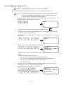
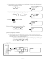
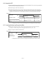
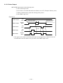
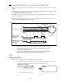
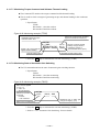
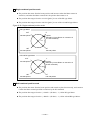
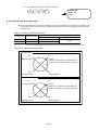
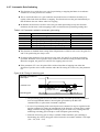
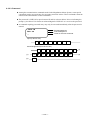
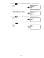
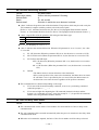
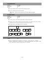
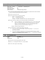
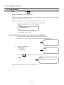
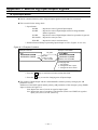
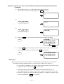
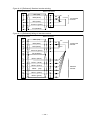
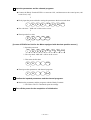
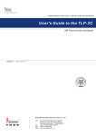
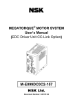
! Caution : Follow the notes below to avoid an electric shock.
◊ The Driver Units have high capacity conductors in its internal circuits, thus resulting in
high residual voltage of the capacitors for few minutes after the power is turned off.
◊ Do not detach a cover of Driver Unit unless it is necessary.
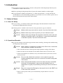
◊ When the cover has to be removed, follow the procedures bellow.
1) Turn off the control and main power.
* If only main power has been turned on, turn the control power on for 5
seconds or more, and then turn off both of them. Neglect of this
procedure is very dangerous because you cannot discharge residual
voltage of capacitors.
2) Wait for 5 minutes or more after the control and main powers were turned off,
and then remove the cover.
Figure 1-1
5 seconds or more *
Control power
ON
OFF
Main power
ON
OFF
5 minutes or over
Remove cover.
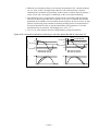
! Caution : Use of an optional regenerative dump resistor shall be considered for
heavy-duty operation.
◊ Megatorque Motors regenerate when they decelerate carrying heavy load inertia.
◊ An internal dump resistor dissipates the regeneration. However, when high and
continuous regeneration is applied, it won’t dissipate excessive regeneration fully, and
it will overheat, and then the Motor will eventually stop under “Abnormal main power
voltage” alarm state.
◊ In such a case, you need to decrease velocity, deceleration rate, and operation duty
cycle, or, you require an external high capacity regenerative dump resistor.
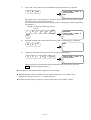
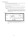
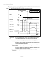
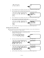
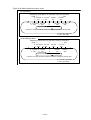
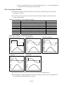
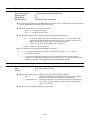
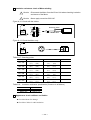
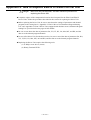
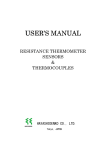
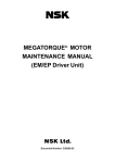
! Danger : Never apply water or oil to the Driver Unit.
◊ Take appropriate measures to protect the Driver Unit from water, oil, slag, dust, and
corrosive gas.
— 1-2 —
Figure 1-2
! Caution : Do not conduct a megger test on the Driver Unit. (It may damage the
internal circuit.)
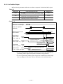
! Caution : In most cases, the Direct Drive Motor System cannot exhibit its full
performance unless the shipping set of the parameters is altered. Refer
to “5. Tuning and Trial Running” for the detail of parameter setting, and
be sure to tune the servo parameters to actual use conditions.
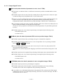
1.1.3. Interchangeability of Motor and Driver Unit
The interchangeability of a Motor and a Driver Unit won’t be applicable to ESA35 and ESAC5
Driver Units. Be sure to make a combination of a Motor and a Driver Unit with the same serial
number. Use the specified cable provided wit the Driver Unit.
Please be advised that the Megatorque Motor System won’t fully exhibit its performance as
described in its specifications if a Motor and a Driver Unit matched with different serial number,
or if you change length of a Cable Set. Especially repeatability of Home Return deteriorates in
case of the System with absolute position sensor.
— 1-3 —
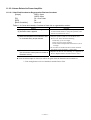
1.2. Terminology
b.p.s. bit per second; the unit of communication speed.
CCW Motor rotating direction, counterclockwise; seen from the outside of rotor.
closed Logic output state; output current will flow.
CW Motor rotating direction, clockwise; seen from the outside of rotor.
Driver Unit Means Megatorque Motor System’s driver unit when capitalized.
Home Return A built-in sequence program for setting the home position.
kpps kilo pulse per second; the unit of pulse frequency.
Motor Means Megatorque Motor System’s motor when capitalized.
OFF (all capital) Logic input state; input will see an open circuit.
ON (all capital) Logic input state; there will be a current path to the common DC supply.
open Logic output state; no output current
P control Proportional-only control; the servo algorithm.
PI control Proportional and integral control; the servo algorithm.
position gain Shorter name for position loop proportional gain
position integrator frequency Shorter name for position loop integrator cutoff frequency
position loop control mode A control mode within the position control loop; P control or PI control available.
Programmable Indexer Driver Unit’s built-in indexing ability.
pulse train A series of pulses used as a position command.
quadrature output Two pulse train outputs with 90° phase difference.
rated stall torque The rated torque available at zero speed.
rated torque The torque not to exceed the maximum Motor winding temperature.
s-1 Revolution per second; the unit of velocity.
s-2 s-1 per second; the unit of acceleration.
servo-lock One typical state of servo-on; the Motor provides torque and remains in position.
servo-off The state where the Driver Unit provides no current to the Motor, and the Motor provides
no torque. The Motor rotor can be rotated easily.
servo-on The state that the Driver Unit is ready to control the Motor, or is controlling the Motor.
shipping set A parameter setting or a Driver Unit function setting at shipping.
stall torque The torque available at zero speed.
System Means Megatorque Motor System when capitalized.
velocity gain (VG) Shorter name for velocity loop proportional gain.
Velocity deviation, which is the difference between velocity command and velocity
feedback signal, is amplified by the amount of parameter VG setting and changed to an
output of torque command.
velocity integrator frequency Shorter name of velocity loop integrator frequency.
(VI) Integral control is to output torque command that is a time quadrature of signals that is an
amplified velocity deviation by proportional gain. The higher VI gives higher output
command than the same level of velocity deviation and time. It is hard to achieve
positioning deviation less than ±1 pulse without the integral control.
velocity loop control mode A control mode within the velocity control loop; P control or PI control available.
— 1-4 —
2. Specifications
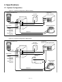
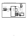
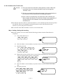
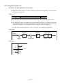
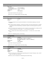
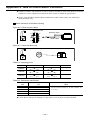
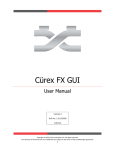
2.1. System Configuration
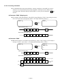
Figure 2-1: System configuration (Without brake)
Handy Terminal FHT11
NSK
24 VDC
power supply
HANDY TERMINAL
1# 2$ 3< 4> 5% -+
6&
7‘
8(
9)
0?
.=
A
B
C
D
E
F
G
H
I
J
K
L
M
N
O
P
Q
R
S
T
U
V
W
Y
Z
?
,
/
*
SHIFT
ESC
CTRL
BS
SP
ENT
• Sequencer
• Motor controller
ESA Driver Unit
X
RS-232C
Main power
3 phase
200 VAC
Single phase
200 VAC
or
Single phase
100 VAC
Megatorque Motor
Cable set
Figure 2-2: System configuration (With break)
Handy Terminal FHT11
NSK
24 VDC
power supply
HANDY TERMINAL
1# 2$ 3< 4> 5% -+
6&
・Sequencer
・Motor controller (pulse train)
7‘
8(
9)
0?
.=
A
B
C
D
E
F
G
H
I
J
K
L
M
N
O
P
Q
R
S
T
U
V
W
Y
Z
?
,
/
*
SHIFT
ESC
CTRL
BS
SP
ENT
ESA Driver Unit
X
RS-232C
Main power
Brake power
24 VDC
3 phase
200 VAC
Single phase
200 VAC
or
Single phase
100 VAC
RS type Motor
with brake
Magnetic relay
Cable set
— 2-1 —
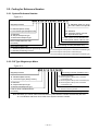
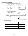
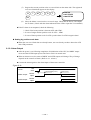
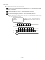
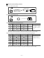
2.2. Coding for Reference Number
2.2.1. System Reference Number
Figure 2-3
M-R S 14 10 F N 001 A A 35 C
C: Standard cable (4 m long)
No code: Cables are optional
Megatorque Motor
R : Standard (Base mount)
A : Low friction type (Flange mount)
35: Standard
C5 : Absolute positoin resolver
F* : Special Driver Unit
S: Standard
W: Simple waterproof type
Z: Reiforced waterproof type
A: Main power source 200/220 VAC
C: Main power source 100/110 VAC
Motor outside diameter code
(In inches)
A: ESA Driver Unit
Motor design number (standard: 001)
Motor stack height code
F : Standard (without absolute positioning resolver)
C: Absolute positioning resolver
N : Standard (No barake)
C : Electromagnetic brake (Power on activated non-backlash type)
D : Electromagnetic brake (Power off activated type)
G : Electromagnetic brake (Power off activated non-backlash type)
2.2.2. RS Type Megatorque Motor
Figure 2-4
M-R S 14 10 F N 001
Megatorque Motor
Motor design number (Standard: 001)
N : Standard (No barake)
C : Electromagnetic brake (Power on activated
R : Standard (Base mount)
A : Low friction type (Flange mount)
non-backlash type)
D : Electromagnetic brake (Power off activated type)
G : Electromagnetic brake (Power off activated
S: Standard
W : Simple waterproof type
Z: Reinforced waterproof type
non-backlash type)
F: Standard (without absolute positioning resolver
C: Absolute positioning resolver
Code for Motor outside diameter
(In inches)
Code for Motor stack height
Note: Generally you cannot order RS sereis Motors by this reference number because they are sold
as a combination with Driver Unit. Refer to the System reference number.
— 2-2 —
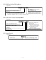
2.2.3. ESA Driver Unit for RS Type Motors
Figure 2-5
M-ESA-1410 A 35
35: Standard
C5: Absolute positoning resolver
F*: Special Driver Unit
ESA Driver Unit for Megatorque Motor
Motor size
A: Main power source 200/220 VAC
Note: Generally you cannot purchase Driver Units with
C: Main power source 100/110 VAC
this reference number because they are sold as a
combination with Motor. Refer to the System reference number.
2.2.4. Cable Set for RS Type Megatorque Motor
Figure 2-6
M-C 004 S S R 05
Cable set for Mgatorque Motor
Cable length (in units of meter)
Max. length: 30 m (Consult with NSK for longer cables)
S: Standard
W: Waterproof
05: Standard (Straight plug)
03: Angle plug
07: Standard straight plug for
absolute positioning resolver
10: Angle plug for absolute
positioning resolver
For RS sereis Megatorque Motor
ESA Driver Unit
2.2.5. Handy Terminal
Figure 2-7
M-FHT 11
Handy Terminal
Handy Terminal design number
— 2-3 —
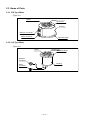
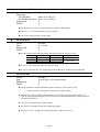
2.3. Name of Parts
2.3.1. RS Type Motor
Figure 2-8
Hollow hole
Rotor
Dust cover
Housing
Resolver connector
Motor connector
Mounting base
2.3.2. AS Type Motor
Figure 2-9
Hollow hole
Mounting flange
Rotor
Resolver
connector
Housing
Motor
connector
— 2-4 —
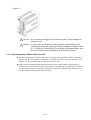
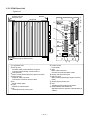
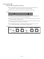
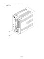
2.3.3. ESA Driver Unit
Figure2-10
Bracket may be
attached here.
Bracket
①
Heat sink
ESA
POWER
DISP.
NSK
○○○○○
○○○○
MOTOR
RS-232C
CN5
FUSE1
250V
T10A
FUSE2
250V
T10A
○○○○○○○○○○○○○
○○○○○○○○○○○○
CN2
I/O
③
CONT.
AC100-220
MAIN
AC200-220V
⑪
VEL.
S
GND
SENSOR
FGND
○○○○○○○
○○○○○○○○
CN3
T
Type
No.
②
⑩
R
⑦
○○○○○○○○○○○○○○○○○○○
○○○○○○○○○○○○○○○○○○
CN1
CN4
⑧
⑬
⑫
VR1 MON. GND
⑨
⑭
PA
NSK-Ltd.
MADE IN JAPAN
No.
Bracket may be attached here.
⑥ ⑤
① 7 segmetns LED
② CN1 (9 pins)
RS-232C serial communication connector
Connect optionla Hnady Terminal FHT11.
③ CN2 (25 pins)
Motor control Input/Output (I/O) signal connector
④ CN3 (15 pins)
Resolver cable connector
Connect the exclusive resolver cable.
⑤ No.
Serial number plate
⑥ Type
Reference number plate
⑦ TB
Terminal block for power input
— 2-5 —
④
⑧ FUSE 1 and 2
Fuse holder
⑨ CN4
Motor cable connector
Connect the exclusive Motor cable.
⑩ Anaog velocity monitor pins
⑪ CN5 (37 pins)
Motor control Input/Output signal connector
(I/O2)
⑫ Analog signal monitor pins
⑬ VR1
Adujsting pod for analog input offset
⑭ Compensation data board unit
Signature board for peculiar characteristics of
a Motor
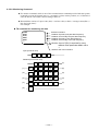
2.3.4. Handy Terminal
Figure 2-11: Handy terminal M-FHT11
26
98
Body
68
Liquid Crystal Display
180
NSK
NSK
1
#
6
&
2
$
7
‘
HANDY TERMINAL
3
<
8
(
4
>
9
)
5
%
0
?
-
+
.
=
A
B
C
D
E
F
G
H
I
J
K
L
M
N
O
P
Q
R
S
T
U
V
W
X
Y
Z
?
,
/
*
SHIFT
ESC
CTRL
BS
SP
ENT
Numeric keys
Code keys (superscript)
Alphabetic keys
Special code keys
SHIFT
ESC
CTRL
BS
SP
ENT
: Shift key Note 1)
: Escape key (Not used)
: Control key (Not used)
: Backspace key Note 2)
:Space key Note 3)
: Enter key Note 4)
Connector socket
DE-C1-J6
Connector
DE-9PF-N
Cable
JAE
DE-C1-J6
86
38
Connector
19
(Cable length 3000 mm)
Note: 1) SHIFT : Press a numeric key while pressing the SHIFT key to enter a code key.
A superscript of the numeric keys will be entered.
2) BS
: Press the BS key when correcting logged in mistakes.
3) SP
: Use this key to input a blank between letters.
4) ENT
: Press the key at the end of a command or the parameter setting
— 2-6 —
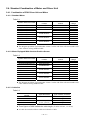
2.4. Standard Combination of Motor and Driver Unit
2.4.1. Combination of ESA Driver Unit and Motor
2.4.1.1. Standard Motor
Table 2-1
System reference number
M-AS0408FN048AA35
M-AS0408FN049AC35
M-RS0608FN001AA35
M-RS0608FN001AC35
M-RS0810FN001AA35
M-RS0810FN001AC35
M-RS1010FN001AA35
M-RS1010FN001AC35
M-RS1410FN001AA35
M-RS1410FN001AC35
Motor reference
number
AS0408FN048
AS0408FN049
RS0608FN001
RS0810FN001
RS1010FN001
RS1410FN001
Driver Unit reference
number
ESA-0408A35
ESA-0408C35
ESA-0608A35
ESA-0608C35
ESA-0810A35
ESA-0810C35
ESA-1010A35
ESA-1010C35
ESA-1410A35
ESA-1410C35
Power
voltage
200 VAC
100 VAC
200 VAC
100 VAC
200 VAC
100 VAC
200 VAC
100 VAC
200 VAC
100 VAC
The Megatorque Motor System that has a letter C on the end of the reference number will
come with a 4 m long standard cable.
2.4.1.2. Motor Equipped With Absolute Position Sensor
Table 2-2
System reference number
M-BS0408CN501AAC5
M-BS0408CN503ACC5
M-RS0608CN001AAC5
M-RS0608CN001ACC5
M-RS0810CN001AAC5
M-RS0810CN001ACC5
M-RS1010CN001AAC5
M-RS1010CN001ACC5
M-RS1410CN001AAC5
M-RS1410CN001ACC5
Motor reference
number
BS0408CN501
BS0408CN503
RS0608CN001
RS0810CN001
RS1010CN001
RS1410CN001
Driver Unit reference
number
ESA-0408AC5
ESA-0408CC5
ESA-0608AC5
ESA-0608CC5
ESA-0810AC5
ESA-0810CC5
ESA-1010AC5
ESA-1010CC5
ESA-1410AC5
ESA-1410CC5
Power
voltage
AC200V
AC100V
AC200V
AC100V
AC200V
AC100V
AC200V
AC100V
AC200V
AC100V
The Megatorque Motor System that has a letter C on the end of the reference number will
come with a 4 m long standard cable.
2.4.1.3. Cable Set
Table 2-3
Cable set reference
number
M-CXXXSSR05
M-CXXXSSR03
M-CXXXSSR07
M-CXXXSSR10
Applicable Motor
Type of Motor connector
Standard
Straight
Angle
Straight
Angle
Absolute position
sensor (resolver)
Three figures of XXX indicate the cable length. (In units of meter, 1 to 30 m)
A Cable Set includes a Motor cable and a Resolver cable.
— 2-7 —
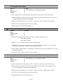
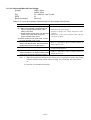
2.4.2. Handy Terminal (For inputting parameters and programs)
Table 2-4: Reference number
Handy Terminal reference number
M-FHT11
— 2-8 —
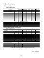
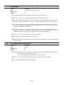
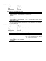
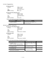
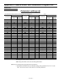
2.5. Motor Specifications
2.5.1. Standard Motor
Table 2-5: Specifications
Motor number
Items [Unit]
Maximum output torque
[N・m]
Maximum current/phase
[A]
Allowable axial load
Allowable moment load
Axial rigidity(1)
Moment rigidity(1)
Maximum stall torque
Rotor moment of inertia
Maximum starting torque
Mass
[N]
[N・m]
[mm/N]
[rad/N・m]
[N・m]
[kg・m2]
[N・m]
[kg]
AS0408
RS0608
RS0810
RS1010
RS1410
9.8
3(200V)
6(100V)
1 760
19
2.55×10⁻⁶
3.06×10⁻⁶
7.8
0.0023
1
6.5
39.2
88.2
147
245
6
7.5
7.5
7.5
3 729
58
4.08×10⁻⁶
3.57×10⁻⁶
33.3
0.0075
3
14
4 500
9 500
19 600
78
156
392
−6
−6
3.06×10
1.42×10
1.01×10⁻⁶
2.55×10⁻⁶ 1.53×10⁻⁶ 3.06×10⁻⁷
137(114(2))
78.5
196
0.020
0.075
0.27
4.5
5.4
7.9
24
40
73
Ambient temperature: 0 to40℃. Humidity: 20 to 80%. Indoor use. Free from
dust, condensation and corrosive gas.
Environmental condition
Maximum velocity
Position sensor resolution
Absolute positioning accuracy
Repeatability
[s−1(rps)]
[pulse/r]
[sec]
[sec]
4.5
409 600
120
±3.2
3
614 400
60
±2.1
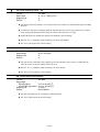
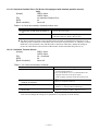
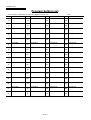
2.5.2. Motor With Absolute Position Sensor
Table 2-6: Specifications
Motor number
Item [Unit]
Maximum output torque
Maximum current/phase
Allowable axial load
Allowable moment load
Axial rigidity(1)
Moment rigidity(1)
Maximum stall torque
Rotor moment of inertia
Maximum starting torque
Mass
[N・m]
9.8
3(200 V)
[A]
6(100 V)
1 760
[N]
[N・m]
19
2.55×10⁻⁶
[mm/N]
[rad/N・m] 3.06×10⁻⁶
[N・m]
7.8
2
[kg・m ]
0.0023
[N・m]
1
7.5
[kg]
RS0608
RS0810
RS1010
RS1410
39.2
88.2
147
245
6
7.5
7.5
7.5
3 729
58
4.08×10⁻⁶
3.57×10⁻⁶
33.3
0.01
3
20
4 500
9 500
19 600
78
156
392
3.06×10⁻⁶ 1.42×10⁻⁶ 1.01×10⁻⁶
2.55×10⁻⁶ 1.53×10⁻⁶ 3.06×10⁻⁷
137(114(2))
78.5
196
0.024
0.088
0.31
4.5
5.4
7.9
33.5
61
98
Ambient temperature: 0 to40℃. Humidity: 20 to 80%. Indoor use. Free from
dust, condensation and corrosive gas.
Environmental condition
Maximum velocity
Position sensor resolution
Absolute positioning accuracy
Repeatability
BS0408
[s−1(rps)]
[pulse/r]
[sec]
[sec]
4.5
409 600
120
±3.2
3
614 400
60
±2.1
* (1) This value is assumed that the Motor is fixed on an ideally solid base.
(2) When the power voltage is 100/110 VAC.
SI unit system 1N = 0.102kgf
1N•m = 0.102kgf•m
— 2-9 —
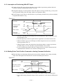
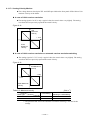
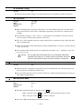
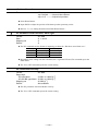
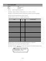
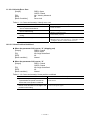
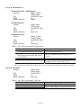
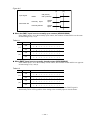
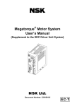
2.5.3. How to Calculate Axial Load and Moment Load
Figure 2-12
F
F
L
L
F
A
(1) If F is an external force, then
(2) If F is an external force, then
(3) If F is an external force, then
Axial load Fa = F + weight of payload
Moment load M = 0
Axial load Fa = F + weight of payload
Moment load M = F × L
Axial load Fa = F + weight of pauload
Moment load M = F × (L + A)
! Caution : Axial load Fa and Moment load M shall be les than allowable axial
load and moment load respectively.
Table 2-7: Dimension A (Unit: mm)
Motor number
Standard
With absolute position
sensor
AS (BS) 0408
25.8
RS0608
18.5
RS0810
18.5
RS1010
27.5
RS1410
30.0
40.4
38.5
38.5
47.5
50
— 2-10 —
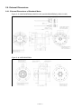
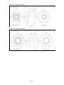
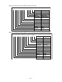
2.6. External Dimensions
2.6.1. External Dimensions of Standard Motor
Figure 2-13: M-AS0408FN048 (200/220 VAC) and M-AS0408FN049 (100/110 VAC)
Figure 2-14: M-RS0608FN001
— 2-11 —
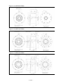
Figure 2-15: M-RS0810FN001
Figure 2-16: M-RS1010FN001
Figure 2-17: M-RS1410FN001
— 2-12 —
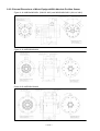
2.6.2. External Dimensions of Motor Equipped With Absolute Position Sensor
Figure 2-18: M-BS0408CN501 (200/220 VAC) and M-BS0408CN503 (100/110 VAC)
Figure 2-19: M-RS0608CN001
Figure 2-20: M-RS0810CN001
— 2-13 —
Figure 2-21: M-RS1010CN001
Figure 2-22: M-RS1410CN001
— 2-14 —
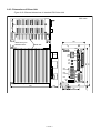
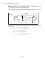
2.6.3. Dimensions of Driver Unit
Figure 2-23: External dimensions of standard ESA Driver Unit
41
30
Unit: mm
20
21.2
20
Bracket may be
attached here.
105
Heat sink
ESA
DISP.
NSK
NSK
○ ○ ○ ○ ○ ○ ○ ○ ○ ○ ○ ○ ○
○ ○ ○ ○ ○ ○ ○ ○ ○ ○ ○ ○
CONT.
AC100-220V
R
MAIN
AC200-220V
VEL.
S
GND
FGND
SENSOR
Type
No. N S K - L t d .
PA
No.
MADE IN JAPAN
(46)
— 2-15 —
6
27.5
50
17.5
205
9
Bracket may be attaced here
○ ○ ○ ○ ○ ○ ○
○ ○ ○ ○ ○ ○ ○ ○
CN3
T
215
CN2
FUSE1
250V
T10A
180
CN5
FUSE1
250V
T10A
RS-232C
○ ○ ○ ○ ○ ○ ○ ○ ○ ○ ○ ○ ○ ○ ○ ○ ○ ○ ○
○ ○ ○ ○ ○ ○ ○ ○ ○ ○ ○ ○ ○ ○ ○ ○ ○ ○
MOTOR
CN1
○ ○ ○ ○ ○
○ ○ ○ ○
CN4
VR1 MON. GND
POWER
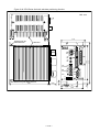
Figure 2-24: ESA Driver Unit with absolute positioning function
41
40
Unit: mm
20
21.2
20
Bracket may be
attached here.
115
Heat sink
ESA
POWER
MON.
GND
DISP.
NSK
NSK
CN1
FUSE1
250V
T10A
CN2
CONT.
AC100-220V
R
VEL.
S
GND
FGND
SENSOR
Type
No. N S K - L t d .
MADE IN JAPAN
9
PA
(46)
— 2-16 —
6
27.5
50
105
17.5
205
No.
○ ○ ○ ○ ○ ○ ○
○ ○ ○ ○ ○ ○ ○ ○
CN3
T
Bracket may be attached here.
180
○ ○ ○ ○ ○ ○ ○ ○ ○ ○ ○ ○ ○
○ ○ ○ ○ ○ ○ ○ ○ ○ ○ ○ ○
FUSE1
250V
T10A
CN5
215
RS-232C
MOTOR
○ ○ ○ ○ ○ ○ ○ ○ ○ ○ ○ ○ ○ ○ ○ ○ ○ ○ ○
○ ○ ○ ○ ○ ○ ○ ○ ○ ○ ○ ○ ○ ○ ○ ○ ○ ○
○ ○ ○ ○ ○
○ ○ ○ ○
CN4
MAIN
AC200-220V
VR1
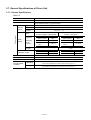
2.7. General Specifications of Driver Unit
2.7.1. General Specifications
Table 2-8
Item
Control system
Operation mode
Control
power
Spec.
Capacity
Inrush
current
Power input
Spec
Main
power
Capacity
Motor number
(Excludes
inrush
current)
0408, 0608
0810, 1010,
1410
Inrush
current
Leakage current
Vibration resistance
Line noise resistance
Mass
Environmental
condition
Specification
Full closed loop P • PI positioning control
Pulse train position command, RS-232C serial communication,
Programmable Indexer, Jog, Home Return
100 to 220 VAC ± 10%, 50/60Hz, single phase
Max 50 VA(excludes inrush current)
200 VAC: 14A
100 VAC: 7A
200 to 220 VAC ± 10%
100 to 110 VAC ± 10%
50/60Hz, single or Three phase
50/60Hz, single phase
Operating
Storage
Capacity
Max.
2.0KVA
2.5KVA
140 A
40 Hz to 1KHz
1KHz to 1MHz
Motor number
0408, 0608
0810, 1010,
1410
Capacity
Max.
1.0 KVA
1.5 KVA
8 0A
5 mA rms
35 mA rms
40 Hz to 1 KHz
1 KHz to 1 MHz
3 mA rms
20 mA rms
0.5 G (Conforms to JIS-C0911)
1500 V, 1µs (By a noise simulator)
Standard 2.9Kg / Absolute position sensor function 3.0Kg
Ambient temperature: 0 to 50°C. Humidity: 20 to 90%
(Free from condensation, dust, and corrosive gas, etc.)
Ambient temperature: 20 to 70°C. Indoor condition.
(Free from condensation, dust and corrosive gas, etc.)
— 2-17 —
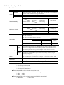
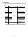
2.7.2. Functional Specifications
Table 2-9
Item
Specification
Programmable Indexer: 64 channels
Position
Pulse train position command: CW/CW, Step and direction, and quadrature)
Control control
RS-232C serial communication, Jog, home Return
mode
Velocity control Analog velocity command: ± 10V, RS-2332C serial communication
Torque control Analog torque command: ± 10V, RS-232C serial communication
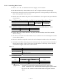
[Unit: pulse/rev]
Resolver
Automatic resolution
resolution
switching or
10 bit setting
Resolution of position
Motor number
12 bit setting
sensor (resolver)
04xx
409 600
102 400
06xx to 14xx
614 400
153 600
Maximum velocity
Resolver
resolution
12 bit setting
Motor size
04xx
06xx to 14xx
1.5
1
[Unit: s-1]
Automatic res0lution
switching or
10 bit setting
4.5
3
Output signal format
øA • øB: Line driver
øZ: Line driver/Open collector selectable.
Position feedback
output signal
øA • øB
Motor size
04xx
06xx to 14xx
Input
Control signal
Output
Alarm
Monitoring
Communication
Data backup
12 bit setting
102 400
153 600
[Unit: pulse/rev]
øZ
(MSB)
10 bit setting
25 600
100
38 400
150
Emergency stop, servo On, Internal program channel switching (64 channels)
Programmable Indexer start, Jog, Home Return start, Select rotational direction,
Interruption of Programmable Indexer, Home position limit switch, Over travel
limit, alarm clear, Velocity loop integration OFF, Lower velocity loop gain,
Prohibition of pulse train/analog command input
Driver Unit ready, Warning, Brake, In-position, Home position defined,
Home Return completed/Home position detected, Velocity threshold, Target
proximity/In target area
Excessive position error, Velocity abnormal, Overload, Over-travel,
CPU error, RS-232C error, Resolver circuit error, Over current, Overheat, Main
AC line trouble, Control AC line under voltage
Analog monitor, Analog velocity monitor, and RS-232C communication monitor
(Current position, Alarm state, Servo parameter setting, etc.)
Asynchronous RS-232C serial communication, Baud rate: 9 600 bps
EEPROM (500 000 times of overwriting/erasing data is possible.)
The parameter SL sets the control mode.
◊ SL1: Torque control mode
◊ SL2: Velocity control mode
◊ SL3: Position control mode
The parameter RR sets the resolution of position sensor.
◊ RR−1 : 10/12 bit automatic resolution switching
◊ RR0 : 10 bit
◊ RR1 : 12 bit
The parameter FR sets the resolution of position feedback output signal.
◊ FR0: 10bit.
◊ FR1: 12bit
— 2-18 —
2.8. RS-232C Interface Specifications
Refer to “6.3. RS-232C Communication” for the specifications of communication.
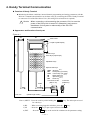
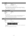
2.8.1. CN1: RS-232C Serial Communication Connector
* Optional Handy Terminal FHT 11 is available for the RS-232C communication terminal.
Table 2-10
Driver Unit connector
Mating connector type
(User device side)
Mating connector shell type
(user device side)
Japan Aviation Electronics Industry, Ltd.
Japan Aviation Electronics Industry, Ltd.
(To be prepared by the user)*
Japan Aviation Electronics Industry, Ltd.
(To be prepared by the user)*
DELC-J9SAF-13L9
DE-9PF-N
DE-C2-J6
* The user shall provide these connectors. They are not necessary if NSK Handy Terminal
FHT 11 is used.
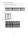
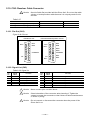
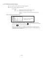
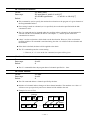
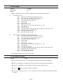
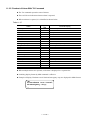
2.8.1.1. CN1 Pin-Out
Figure 2-25: CN1 Pin-out
FG
+5V
RTS
SG
5
9
4
8
3
7
2
6
1
DTR
DSR
RXD
CTS
TXD
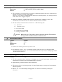
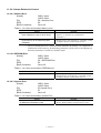
2.8.1.2. CN1 Signal List
Table 2-11: Signal name and function (CN1)
Pin
1
2
3
4
5
6
7
8
9
Signal name
TXD
CTS
RXD
DSR
DTR
SG
RTS
+5V
FG
I/O
Output
Input
Input
Input
Output
–
Output
Output
Function
Transmit data
Clear to send
Receive data
Data set ready
Data terminal ready
Digital signal ground
Ready to send
Never connect
Frame ground (shield)
— 2-19 —
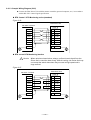
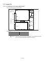
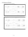
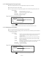
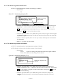
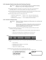
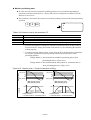
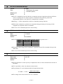
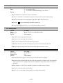
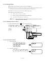
2.8.1.3. Sample Wiring Diagram (CN1)
Connect the ESA Driver Unit with the master controller (personal computer, etc.) in accordance
with its RS-232C control signal specification.
RTS Control / CTS Monitoring active (standard)
Figure 2-26
ESA Driver Unit
RS-232C terminal
CN1
TXD
1
TXD
RXD
3
RXD
RTS
7
RTS
CTS
2
CTS
DSR
4
DSR
DTR
5
DTR
SG
6
SG
FG
9
FG
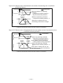
RTS control/CTS Monitoring inactive
! Caution : When wired as shown below, always confirm the echo-back from the
Driver Unit or send the data slowly. With this wiring, the Driver Unit may
not accept the whole data when they are sent at high speed and in
large amount.
Figure 2-27
ESA Driver Unit
RS-232C Terminal
CN1
TXD
1
TXD
RXD
3
RXD
RTS
7
RTS
CTS
2
CTS
DSR
4
DSR
DTR
5
DTR
SG
6
SG
FG
9
FG
— 2-20 —
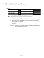
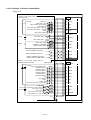
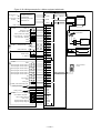
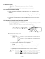
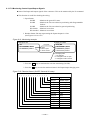
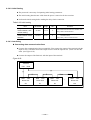
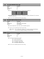
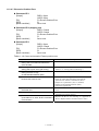
2.9. CN2 and CN5: Control I/O Signal Connector
Table 2-14 shows types of connectors that are used for connectors CN2 and CN5 and
connectors for user side devices.
Table 2-12
Connectors for Driver Unit
Mating connectors
(User device side)
Mating connector shell type
(User device side)
CN2
CN5
CN2
CN5
CN2
CN5
DBLC-J25SAF-13L9
DCLC-J37SAF-13L9
DB-25PF-N*
Japan Aviation Electronics Industry, Ltd.
DC-37PF-N*
DB-C15-J10-F2*
Japan Aviation Electronics Industry, Ltd.
DC-C8-J13-F1-1*
Japan Aviation Electronics Industry, Ltd.
* These connectors shall be provided with the Driver Unit.
The followings are the wiring precautions for connectors CN2 and CN5.
1)
Use shielded cable for wiring the connectors CN2 and CN5.
2)
Twisted cables must be used for the pulse train input and the position feedback signal.
3)
These cables should be laid separately from the power line. Wiring length shall be
short as possible. (2 m maximum)
4)
Connect one end of shield to the frame ground. Refer to “3.3.4. Ground Connection
and Wiring.”
! Caution : Check for wiring mistake in the polarity of external power supply, and
shorting between connector pins.
— 2-21 —
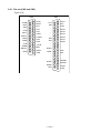
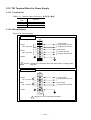
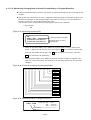
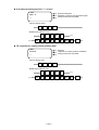
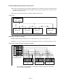
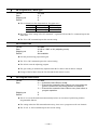
2.9.1. Pin-out (CN2 and CN5)
Figure 2-28
CN2
SVON
IOFF
HOS
OTM
CWPCCWP*CHA
*CHB
CHZ
SGND
DRDY+
IPOS
25
24
23
22
21
20
19
18
17
16
15
14
13
12
11
10
9
8
7
6
5
4
3
2
1
CN5
DC24
EMST
HLS
CLR
OTP
CWP+
CCWP+
CHA
CHB
*CHZ
BRK
DRDYCOM
LVG
INH
−
−
−
−
DIR
JOG
−
−
MON+
MON−
−
−
HCMP
HOME
SPD
— 2-22 —
37
36
35
34
33
32
31
30
29
28
27
26
25
24
23
22
21
20
19
18
17
16
15
14
13
12
11
10
9
8
7
6
5
4
3
2
1
DC24
STP
RUN
PRG5
PRG4
PRG3
PRG2
PRG1
PRG0
−
−
AIN+
AIN−
−
NEARB
NEARA
OVER
COM
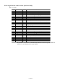
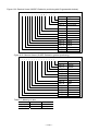
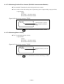
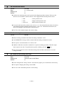
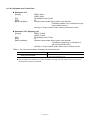
2.9.2. Signal Name and Function (CN2 and CN5)
Tale 2-13: CN2
Pin
1
2
3
4
5
6
7
8
9
10
11
12
13
14
15
16
17
18
19
20
21
22
23
24
25
Signal Name
COM
DRDYBRK
∗CHZ*
CHB
CHA
CCWP+
CWP+
OTP
CLR
HLS
EMST
DC24
IPOS
DRDY+
SGND
CHZ*
∗CHB
∗CHA
CCWPCWPOTM
HOS
IOFF
SVON
I/O
Output
Output
Output
Output
Output
Output
Input
Input
Input
Input
Input
Input
Input
Output
Output
–
Output
Output
Output
Input
Input
Input
Input
Input
Input
Function
Output COMMON
Driver Unit ready (-)
Brake control signal (normally closed)
Position feedback signal øZ/digital position data ∗MSB*
Position feedback signal øB
Position feedback signal øA
Counter clockwise pulse train (+)
Clockwise pulse train (+)
+ direction over travel limit switch (CW direction)
Clear
Home limit switch
Emergency stop
24 VDC external supply
In position
Driver Unit ready (+)
Signal ground
Position feedback signal øZ / digital position data MSB*
Position feedback signal ∗øB*
Position feedback signal ∗øA*
Counter clockwise pulse train (-)
Clockwise pulse train (-)
- direction, over travel limit switch (CCW direction)
Home Return start
Integration OFF
Servo-ON
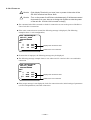
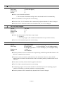
* The parameter FZ (RS-232C communication interface) selects the position feedback
signal øZ or the digital position signal ∗MSB.
— 2-23 —
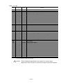
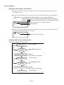
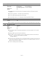
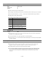
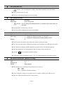
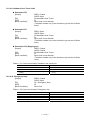
Table 2-14: CN5
Pin
1
2
3
4
5
6
7
8
9
10
11
12
13
14
15
16
17
18
19
20
21
22
23
24
25
26
27
28
29
30
31
32
33
34
35
36
37
Signal
name
COM
OVER
NEARA
NEARB
−
−
AIN−
AIN+
−
−
PRG0
PRG1
PRG2
PRG3
PRG4
PRG5
RUN
STP
DC24
SPD
HOME
HCMP
−
−
−
MON−
MON+
−
−
JOG
DIR
−
−
−
−
INH
LVG
I/O
Output
Output
Output
Output
−
−
Input
Input
−
−
Input
Input
Input
Input
Input
Input
Input
Input
Input
Output
Output
Output
−
−
−
Output
Output
−
−
Input
Input
−
−
−
−
Input
Input
Function
Output COMMON
Warning
Target proximity A/In target A(1)
Target proximity B/In target B(1)
Do not connect
Do not connect
Analog command input (-)
Analog command input (+)
Do not connect
Do not connect
Programmed move • Channel switch 0
Programmed move • Channel switch 1
Programmed move • Channel switch 2
Programmed move • Channel switch 3
Programmed move • Channel switch 4
Programmed move • Channel switch 4
RUN move
Stop
24 VDC external power supply
Velocity threshold
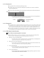
Home Return completed/ Home position detected(1)
Home position defined
Do not connect
Do not connect
Do no connect
Analog monitor output (-)
Analog monitor output (+)
Do not connect.
Do not connect.
Jog
Jog direction
Do not connect.
Do not connect.
Do not connect.
Do not connect.
Inhibit pulse train / Analog command input
Lower velocity loop proportional gain.
* (1) A parameter selects the function.
! Caution : Follow respective specification documents of a custom made
Megatorque Motor System for specially arranged Input/Output signals.
— 2-24 —
2.9.3. Setting the Polarity of the Input Ports (Normally open or closed contacts)
You may change the polarity of some CN2 input ports.
The all input polarity is set to the normally open contact for shipping set.
The parameter AB sets the polarity of input ports.
You require entry of the password before inputting the parameter AB.
Polarity change is only available for signals EMST, HLS, OTP, and OTM.
Refer to Table 2-15 for arrangement of the signal names. (From left, EMST is on the second
signal, HLS on the fourth, OTM on the seventh, and OTP on the eighth.)
Table 2-15
CN2 No.
Signal name
25
SVON
12
EMST
24
IOFF
11
HLS
23
HOS
10
CLR
22
OTM
9
OTP
Meaning of data
0 = Normally open (A contact)
1 = Normally closed (B contact
X = The port indicated by X does not need to change the polarity when setting signal
polarity. In case of reporting the status of polarity of signals, you cannot change
the polarity of a signal that coded to X. The polarity of the signal indicated by X
is set to “normally open contact (A contact).”
Example of polarity setting
Set the polarity of the signal EMST (Emergency stop) to the normally closed contact (B contact).
(1) Input the code key while pressing the shift key.
SHIFT
0?
:
:?_
(2) Input the readout command AB and confirm the current polarity setting. (The example
below shows that the polarity of all signals is the normally open contact (A contact.)
A
B
:
:?AB
ABX0X0XX00
:_
ENT
(3) Input the password. The acknowledgement will be on the screen.
/
N
S
O
N
ENT
K
ABX0X0XX00
:/NSK ON
NSK ON
:_
SP
(4) Input “1” to the EMST (the second one) and remain X (unchanged) for the other signals.
Thus the polarity of EMST signal is changed to the normally closed contact.
A
B
X
1#
X
X
X
X
X
ENT
— 2-25 —
X
:/NSK ON
NSK ON
ABX1XXXXXX
:_
2.9.4. Electrical Specifications of Signals (CN2 and CN5)
2.9.4.1. General Input Signals
Applicable inputs: SVON, EMST, PRG0 to 5, RUN, HOS, HLS, JOG, DIR, OTP, OTM, CLR,
IOFF, LVG, STP, and INH
Table 2-16
Item
Input voltage
Input impedance
Specification
24 VDC ±10%
3.3 kΩ
10 mA or less (per one
contact)
Maxi. current
Figure 2-29
*
3.3 kΩ
680 kΩ
DC24
Input
Driver Unit side
* You may reverse the polarity of 24 VDC external supply and connect as “minus
common.”
2.9.4.2. Pulse Train Command
Applicable inputs: CCWP+, CCWP−, CWP+, and CWP−
Table 2-17
Item
Input voltage
Input impedance
Max. current
Specification
5 VDC ±10%
240 Ω
25 mA or less
Figure 2-30
120 Ω
Input -
390 Ω
120 Ω
Input+
Driver Unit side
— 2-26 —
2.9.4.3. General Output Signal
Applicable outputs: BRK, IPOS, OVER, HOME, HCMP, SPD, NEARA, and NEARB
Table 2-18
Item
Max. load capacity
Maxi, saturated voltage
Specification
24 VDC/100mA
2 V or less
Figure 2-31
Output
* COM
Driver Unit side
* Connect a corresponding output signal connectors CN2 and CN5 for the output
COMMON.
2.9.4.4. Alarm Output
Applicable outputs: DRDY+ , and DRDYTable 2-19
Item
Max. load capacity
Maxi. saturated voltage
Specification
24 VDC/100mA
2 V or less
Figure 2-32
Ouput +
Output Driver Unit side
— 2-27 —
2.9.4.5. Position Feedback Signal Output
Applicable outputs: CHA, CHB, CHZ, *CHA, *CHB, and *CHZ
Table 2-20
Item
Specification
• Line driver (CHA, CHB, *CHA, and *CHB)
• Line driver or Open collector (CHZ, and *CHZ) (May be selected by Jumper
JP1: Refer to “2.13.1. JP1.”)
Texas Instruments: SN75ALS192
Output format
Line driver
Recommended line
receiver
Max. collector current
Max. collector voltage
Saturated voltage
Texas Instruments: SN75ALS193 or AM26LS32 equivalent
100 mA
24 V
1 V or less
When the signal format is open collector,
Figure 2-33
JP1
3 OC
CHA
CHB
*CHZ
*CHA
*CHB
SGND
CHZ
1 LD
SGND
Driver Unit side
Driver Unit side
2.9.4.6. Analog Command Input
Applicable inputs: AIN+, and AINTable 2-21
Items
Max. input voltage
Input impedance
Max. input current
Specification
± 10 V
20 kΩ
0.5 mA
Figure 2-34
20 kΩ
AIN+
AIN-
−
+
Driver Unit side
— 2-28 —
2.9.4.7. Analog Monitor
Applicable outputs: MON+, and MONTable 2-22
Item
Output format
Max. output voltage
Saturated current
Specification
Ope-amp
± 10 V ±10%
4 mA or less
Figure 2-35
10k Ω
1000PF
−
MON+
+
MON−
10k Ω
— 2-29 —
2.9.5. Wiring Connectors (CN2, and CN5)
! Caution : • Be sure to install a surge killer circuit when inductive switches, such
as relays, are used.
• When you install sensors such as “Home position limit switch,”
“+ direction sensor of over travel limit switch” and “- direction of over
travel limit switch,” connect output of those sensors directly, not via a
in the following
controller. (Those outputs are shown as
figures.)
2.9.5.1. Example of Velocity/Torque Control Mode
Figure 2-36
User’s controller
Polarity of the power supply may be reversed to minus
cokkon.
24 VDC
CN2
13 24 VDC
Servo on
Emergency stop
Over travel limit sensor, + direction
Over travel limit sensor, - direction
Clear
Integration off (velocity control mode only)
25
12
9
22
10
24
SVON
EMST
OTP
OTM
CLR
IOFF
Driver Unit ready
15
2
14
3
1
DRDY +
DRDY IPOS
BRK
COM
6
19
5
18
17
4
16
CHA
∗CHA
CHB
∗CHB
CHZ
∗CHZ
SGND
24 VDC
Positioning completed
Brake control signal
Position feedback signal øA
Position feedbacke signal øB
Position feedback signal øZ
/digital position signal MSB
Signal ground
(Velocity/ Torque control mode)
Analog command input*
± 10 VDC
8
7
CN5
AIN +
AIN –
24 VDC
24 VDC
LVG
INH
Lower gain (for velocity control only)
Prohibit analog command input
24 VDC
ESA Driver Unit
OVER
SPD
NEARA
NEARB
COM
Warning
Velocity report
In target A
In target B
FG
— 2-30 —
2.9.5.2. Example of Position Control Mode
Figure 2-37
User’s controller
Polarity of the power supply may be reversed to
minus common.
CN2
13 24 VDC
24 VDC
Servo on
Emergency stop
Home postion limit sensor
Integration off
Over travel limit sensor, + direction
Over travel limit sensor, – direction
Clear
Start Home Return
5 VDC
CW pulse train
CCW pulse train
Driver Unit ready
24 VDC
Positioning completed
Brake control signal
Position feddbacke signal øA
Position feedback signal øB
Position feedback signal øZ
/digital position signal MSB
Polarity of the power supply may be
reversed to minus common.
Signal ground
24 VDC
Start programmed move.
Channel select 5
Channel select 4
Channel select 3
Channel select 2
Channel select 1
Channel select 0
Jog
Jog direction
Stop
Lower gain
Prohibit pulse train/analog command input
Warning
Home Retrun completed/Home postion detected
24 VDC
Home postion defined
Detect velocity
Target proximity A /In target A
Target peoximity B/ In target B
F•G
— 2-31 —
ESA Driver Unit
25
12
11
24
9
22
10
23
SVON
EMST
HLS
IOFF
OTP
OTM
CLR
HOS
8
21
7
20
CWP +
CWP CCWP +
CCWP -
15
2
14
3
1
DRDY +
DRDY IPOS
BRK
COM
6
19
5
18
17
4
16
CHA
∗CHA
CHB
∗CHB
CHZ
∗CHZ
SGND
CN5
19 24 VDC
17
16
15
14
13
12
11
30
31
18
37
36
RUN
PRG5
PRG4
PRG3
PRG2
PRG1
PRG0
JOG
DIR
STP
LVG
INH
2
21
22
20
3
4
1
OVER
HOME
HCMP
SPD
NEARA
NEARB
COM
2.9.5.3. Application of Mechanical Brake
A brake unit for RS series Motors is an electromagnetic brake that functions by the application
of current to its coil. There are two types of brake: power-on activated electromagnetic brake
that functions by tuning on the power to the coil, and power-off activated brake that functions by
turning off the current to the coil.
Table 2-23: Electromagnetic brake for RS series Motors
Type
Power-on activated type
(Non-backlash)
Power-off activated type
Power-off activated type
(Non-backlash)
Function
・High braking power holds the Motor position tightly when external force in
rotational direction is applied in case of machining, etc.
・Brake for power shut down or emergency stop.
・High braking power.
・Brake for power shut dawn or emergency stop.
・Suites for application that requires accurate position holding.
◊ The brake must be kept in completely dry condition. Be sure to maintain the friction
plate absolutely free from oil so that not to lose braking torque.
◊ The electromagnetic brake uses a lot of soft materials. Hammering, dropping, or
application of excessive external force may create internal damage or deformation.
This may result in a brake malfunction or a drop of braking torque.
Table 2-24: Specifications of power-on activated electromagnetic brake
Motor reference
number
M-RS0608FC001
M-RS0810FC001
M-RS1010FC001
M-RS1410FC001
Static friction
torque [N•m]
49
88.2
147
245
Torsion rigidity
[arc-sec/N・m]
0.66
0.70
0.54
0.33
Engaging
time [sec]
0.031
0.035
0.053
0.053
Releasing
time [sec]
0.049
0.093
0.081
0.121
Power
voltage
24 VDC
24 VDC
24 VDC
24 VDC
Capacity
[W]
36
40
46
64
Power
voltage
24 VDC
24 VDC
24 VDC
24 VDC
Capacity
[W]
36
40
46
64
Table 2-25: Specifications of power-off activated electromagnetic brake
Motor reference
number
M-RS0608FD001
M-RS0810FD001
M-RS1010FD001
M-RS1410FD001
Static friction
torque [N•m]
49
88.2
147
245
Torsion rigidity
[arc-sec/N・m]
6
6
7
6
Engaging
time [sec]
0.135
0.220
0.240
0.280
Releasing
time [sec]
0.102
0.020
0.038
0.092
Table 2-26: Specifications of power-off activated non-backlash electromagnetic brake
Motor reference
number
M-RS0608FG001
M-RS0810FG001
M-RS1010FG001
M-RS1410FG001
Static friction
torque [N•m]
29.4
49
88.2
147
Torsion rigidity
[arc-sec/N・m]
0.51
0.31
0.15
0.13
— 2-32 —
Engaging
time [sec]
0.158
0.164
0.257
0.295
Releasing
time [sec]
0.036
0.030
0.044
0.074
Power
voltage [V]
24 VDC
24 VDC
24 VDC
24 VDC
Capacity
[W]
36
40
46
64
The user’s master controller must control the brake control circuit.
Figure 2-38: Recommended sequence
When a brake is for a
saftey stopper.
Power source
ON
OFF
SVON input
ON
OFF
BRK output
Closed
Open
RUN input
IPOS output
When a brake is to cover
Motor’s position holding
reigidity.
When an alarm that makes
“servo free” arises.
ON
OFF
Brake releasing time + α
Closed
Open
Motor motion
User side
ON(release)
brake
OFF(engage)
signal
IOFF input
LVG output
ON
OFF
Brake engaging time + α
! Caution : • When braking the Motor under the servo lock state, be sure to
deactivate integration control in velocity loop (IOFF input ON).
Otherwise the Motor will overheat and create a dangerous situation.
• Take an enough time for locking the Motor by brake when deactivate
the integration control in velocity loop. If you deactivate the integration
control before locking the Motor, stopping accuracy of the Motor will
deteriorate.
• Do not turn the servo OFF when locking the Motor by the brake in the
pulse train command operation. Otherwise accuracy of stopping
position error will be accumulated because errors in the position error
counter are cleared every time the brake is on.
— 2-33 —
Figure 2-39: Wiring example for a Motor equipped with brake
ESA Driver Unit
ø3 200 VAC R
or
ø1 200 VAC S
100 VAC
T
• Isolation transdormer
CONT
• Cicuit breaker
• Electromagntic switch
MAIN
• Noise filter, etc
CN4
MOTOR
TB
Megatorque Motor
FGND
CN3
SENSOR
Mater controller (User’s controller)
13 DC24
Servo on
25 SVON
Emergency stop
12 EMST
24 VDC
Home Return start
23 HOS
Home positon limit switch
11 HLS
Over travel lmit + direction
9
22 OTM
IOFF
24 IOFF
10 CLR
8
5 VDC
24 VDC
CWP+
CW pulse train
21 CWP-
CCW pulse train
20 CCWP-
7
Driver Unit ready
Surge absorber
OTP
Over travel limit – direction
Clear
• The user shall provide these circuit.
RL1
CN2
GND
User’s master controller
CCWP+
RL1
24 VDC
15 DRDY+
Brake control
2 DRDYBrake output
In position
Brake power supply
24 VDC
3 BRK
14 IPOS
1 COM
19 DC24
24 VDC
RUN
17 RUN
Internal program channel switch 5
16 PRG5
Internal program channel switch 4
15 PRG4
NSK
6
Internal program channel switch 3
14 PRG3
Internal program channel switch 2
13 PRG2
Internal program channel switch 1
12 PRG1
Internal program channel switch 0
11 PRG0
Jog
31 DIR
Stop
18 STP
Lower gain
37 LVG
Prohibit pulse train/analog input
Analog command
CN1
30 JOG
Jog direction
36 INH
8
AIN+
7
AIN-
CN5
27 MON+
Analog monitor
24 VDC
26 MONWarnig
Home Return completed
Home position defined
SPD output
2 OVER
21 HOME
22 HCMP
20 SPD
Target proximity/In target A
3 NEARA
Target proximity/In target B
4 NEARB
Handy Terminal
FHT11
HANDY TERMINAL
1# 2$ 3< 4> 5% -+
1 COM
— 2-34 —
RS-232C
&
7
‘
8
(
C
9
)
D
0
?
.
A
B
G
H
I
M
N
O
P
Q
R
S
T
U
V
W
X
Y
Z
?
,
/
*
SHIFT
ESC
CTRL
BS
SP
ENT
J
E
=
K
F
L
2.10. CN3: Resolver Cable Connector
! Caution : Use the Cable Set provided with the Driver Unit. Do not cut the cable
shorter or hookup another cable because it is uniquely made for the
resolver.
Table 2-27
Driver Unit connector
Mating connector type* (user side)
Mating connector shell type* (user side)
Japan Aviation Electronics Industry
Japan Aviation Electronics Industry
Japan Aviation Electronics Industry
DALC-J15SAF-13L9
DA-15P-N*
DA-C1-J10*
* Provided with the Cable Set.
2.10.1. Pin-Out (CN3)
Figure 2-40: Pin-out
ESA Driver Unit
REC
FG
15
14
13
12
11
10
9
8
7
6
5
4
3
ESA with absolute position sensor
REA
FG
15
14
13
12
11
10
REc-
9
REC
REB
REc+
COMMON
2
1
8
7
REA
6
5
4
3
REa+
2
1
REb-
REB
REb+
COMMON
REa-
2.10.2. Signal List (CN3)
Table 2-28: Signal list
Pin
No.
8
7
15
4
10
Signal
name
REA
REB
REC
COMMON
FG
Function
Resolver signal øA
Resolver signal øB
Resolver signal øC
Common
Frame ground
Pin
No.
6
3
5
2
14
9
Signal
name
REa+
REaREb+
REbREc+
REc-
Function
Absolute resolver signal øa +
Absolute resolver signal øa Absolute resolver signal øb +
Absolute resolver signal øb Absolute resolver signal øc +
Absolute resolver signal øc -
! Caution : Never connect pins not listed above.
! Caution : Check orientation of the connector when inserting it. Tighten the
screws to secure the connector so that it does not disconnect because
of shock or pulling.
! Caution : Do not connect or disconnect the connecter when the power of the
Driver Unit is on.
— 2-35 —
2.11. CN4: Motor Connector
! Caution : Use the Cable Set provided with the Driver Unit. You cannot cut the
cable or hookup to other cable as the Cable Set is specially made for
the Megatorque Motor.
Table 2-39
Connector of Driver Unit
Mating connector (user side)
Mating connector shell type (user side)
Tyco Electronics AMP K.K.
Tyco Electronics AMP K.K.
Tyco Electronics AMP K.K.
172039-1
172495-1*
172774-1*
* Provided with the Driver Unit.
2.11.1. CN4 Pin-Out
Figure 2-41: Pin-out
C+
5
1
A+
C–
6
2
A–
3
B+
4
B–
E
7
2.11.2. CH4 Signal List
Table 2-30: Signal list
Pin
1
2
3
4
5
6
7
Signal
Name
A+
A–
B+
B–
C+
C–
E
Function
Motor winding øA (+)
Motor winding øA (–)
Motor winding øB (+)
Motor winding øB (–)
Motor winding øC (+)
Motor winding øA (–)
Motor winding ground
! Danger : Do not connect or disconnect the connector if the power of Driver Unit
is on.
! Danger : A high voltage is applied to the connector after the power is turned on.
Be sure not to shorten the pins.
! Danger : Check the orientation of the connector when inserting it. Though the
connector is self-lock type, be sure to insert it to the bottom. Otherwise
you cannot secure the connector.
— 2-36 —
2.12. TB: Terminal Block for Power Supply
2.12.1. Terminal List
Table 2-31: Terminal code and function 端子記号と機能
Terminal
code
CONT
MAIN
FGND
Function
Control power input
Main power input
Frame ground
2.12.2. Wiring Diagram
Figure 2-42: wiring diagram
In case of 200 VAC
TB
Control power
Single phase 100 VAC
Single phase 200 VAC
CONT
100 – 220 VAC
R
MAIN
200 – 220 VAC
Main power
3 phase 200 VAC
Single phase 200 VAC
S
T
FGND
! Caution: Connect R-S terminals when the main power is single phase
200 VAC.
In case of 100 VAC
TB
CONT
100 –110 VAC
Control power
Single phase 100 VAC
MAIN
100 – 110 VAC
Main power
Single phase 100 VAC
FGND
! Caution: Do not connect this terminal.
— 2-37 —
2.13. Jumper Pin
2.13.1. JP1 (Selection of øZ output signal format)
Figure 2-43: Arrangement of jumper pins
7 segments
LED
CN1
Front panel side
CN5
CN2
JP1
OC
LD
CN3
Table 2-32
Pin setting
LD short (shipping set)
OC short
ø Z output signal format
Line driver
Open collector
! Caution : Remove the panel referring to “Appendix 4. How to Replace the ESA
Driver Unit” when changing the setting of the jumper.
— 2-38 —
2.14. Dimensions of Cable Set
Figure 2-44: Standard cable (M-CXXXSSR05)
Figure 2-45: Cables for the system with function of absolute positioning (M-CXXXSSR07)
— 2-39 —
3. Unpacking • Installation • Wiring
3.1. Unpacking
3.1.1. Receiving Check
1) Megatorque Motor
2) Driver Unit
3) Cable Set (Motor and resolver cables)
4) Accessories
◊ CN2 and CN5 mating connectors for control I/O signals (for user devices)
◊ Fuse (2 sets)
3.1.2. Combination of Motor and Driver Unit
! Caution : Confirm that the serial numbers of Motor and Driver Unit indicated on
respective nameplates are the same.
Figure 3-1: Nameplate of Motor
REF.NO.
M-RS 14 10 FN001
SERIAL NO.
140123
Serial number
Motor type code
Motor outside diameter code
Motor stack height code
Figure 3-2: Nameplate of Driver Unit
Type
ESA- 14 10 A35-21
No.
Version number
Motor outside diameter code
Motor stack height code
— 3-1 —
140123-456
Serial number
3.2. Installation
3.2.1. Motor
! Caution : Confirm that how your Motor is graded for dustproof and waterproof.
You cannot use the Megatorque Motor in the environment with
chemicals or paint fumes.
◊ Standard Megatorque Motors (RS, AS, and BS types)
They are not made to dustproof or waterproof specification. (Equivalent to IP20,
IP30 or IP40) You may not expose them to humid or oily environment.
◊ Simple waterproof Motor (RW type)
Some part of the Motor is not completely waterproofed. Confirm what part is
not waterproofed with the specification document, and then take appropriate
measures to the part against water and dust if necessary. For a long time use of
the Motor, we recommend checking the aging trend of Motor with periodical
insulation test approximately once in every half year. You cannot use this type
of Motors unless you take the measures against the environment with water or
oil.
◊ Waterproof Motor (RZ type: IP65 equivalent)
Use this type of Motor when continually splash water or oil on it. Provide air
purge when you use the Motor in IP66 or equivalent condition. Be sure to
supply a dry air. The user shall take the measures against dust. For a long term
use, check the Motor for its aging by insulation test (approximately once in
every half year).
3.2.1.1. Mounting Motor
! Caution : Fix the Motor to the mounting base using the bolt holes on the Motor
flange or the tap holes on the bottom of Motor.
Flatness of the mounting surface shall be 0.02 mm or less.
3.2.1.2. Attaching Load (Work) to Motor
! Warning : Use the tap holes on the rotor to fix an attachment. Fasten the bolts
securely so that there is no looseness between the rotor and the
attachment (work).
3.2.1.3. Confirmation of Load Inertia
The load inertia is generally much higher than the rotor inertia in the Megatorque Motor System.
The measures of allowable load inertia for each Motor size are shown in Table 3-1.
[Unit: kgm2]
Table 3-1
Motor size
0408
0608
0810
1010
1410
High speed positioning
0.01 to 0.05
0.05 to 0.2
0.11 to 0.45
0.18 to 0.75
0.31 to 1.25
General use
0.05 to 0.5
0.2 to 2
0.45 to 4.5
0.75 to 7.5
1.25 to 12.5
High inertia (Low speed)
0.5 to 1
2 to 2.5
4.5 to 5
7.5 to 37.5
12.5 to 125
! Caution : Check the maximum thrust and moment loads.
Refer to the specifications of Motor for more details.
— 3-2 —
3.2.2. Driver Unit Mounting
! Caution : (1) Ambient temperature
Keep the ambient temperature of the Driver Unit between 0 to 50°C. You
cannot use the Driver Unit in an atmosphere over 50°C. Keep a clearance of 100
mm in upper and lower sides of the Driver Unit when it is installed in an
enclosure. If the heat is built up at the upper side of the Driver Unit, provide
ventilation openings on the top of it or equip an air cool unit to take the heat out
of the Driver Unit. (Measures against contamination are required for the
ventilation openings.)
(2) Dust-proof • Waterproof
Put the Driver Unit in an enclosure of which protection code is the IP54 or
better. Protect the Driver Unit from oil-mist, cutting oil, metallic chips and paint
fumes etc. Otherwise it may result in failure of electric circuits of the Driver
Unit because of contamination through the opening of the Driver Unit.
• The IP code is specified in the IEC standard and classifies the protection
level of enclosures from solid contamination and water.
Protection against external solid contamination (5): Dustproof
Protection against water (4): Must not be affected by water splash in any
direction.
! Caution : When installing two or more Driver Units for multi-axis combinations,
provide a space of approximately 100 mm between adjacent Driver
Units.
Inside temperature of the enclosure into which the Driver Unit is installed shall be maintained
between 0 to 50°C. If the Driver Unit frequently gives “Heat sink over temperature” alarm,
provide a forced cooling to the heat sink. (Refer to “11. Alarm” for more details.
You may use brackets to fix an ESA Driver Unit to the enclosure.
100 mm
or more
100 mm
or more
Figure 3-3
— 3-3 —
3.3. Wiring
3.3.1. Motor Wiring
! Caution : Do not make the Motor cable shorter or longer. You need to purchase
separately the cable with specified length if necessary. Ask your local
NSK representative for more details.
! Caution : Do not place the power lines (AC main power and Motor cable) and the
signal lines in close proximity. Do not tie wrap them, and not to put in
the same duct.
Figure 3-4: AS type Megatorque Motor
To CN3
To CN4
Figure 3-5: RS type Megatorque Motor
To CN3
To CN4
— 3-4 —
3.3.2. Connecting Main Power
Refer to “2.12. TB: Terminal Block for Power Supply” for more details.
Provide anti-heat vinyl cables with the size of 2 mm2 or larger for the main power supply.
Do not place the main power line cables and the signal wires in close proximity. Do not tie wrap
them, and not put them in the same duct.
Install a noise filter between the power source and the Driver Unit to protect the System from the
external noises.
Table 3-2: [Reference] Recommended noise filter for main power [Manufacturer: Tokin]
Power source
Single phase: 100 and 200 VAC
Three phase: 200 VAC
Type
LF-215
LF-310
Rated voltage
Rated current
250 V AC/DC
15 A AC/DC
Table 3-3[Reference] Recommended noise filter for control power [Manufacturer: Tokin]
Type
GT-2050
Rated voltage
250 V AC/DC
定格電流
5 A AC/DC
Separate the wiring of the transformer, the primary and the secondary noise filters, and take
different routing.
The Driver Unit and the noise filter shall be close to each other. Do not install magnetic switches
or relays between them.
Be sure to install the surge killer circuit to the coils of magnetic switches, relays and solenoids.
An inrush current flows when the power is turned on because the capacitive load is connected to
the main power supply circuit. For this reason, use the contacts, if necessary, such as magnetic
switch that have higher rated current as shown below.
Table 3-4
Contacts
Non-fuse breaker
Short circuit breaker
Magnetic switch
For ESB23
Rated current: 15 A
Rated current: 15 A,
Sensitivity: 15 mA
Rated current: 15 A (Mesh current: 15 times or more of rated current)
Table 3-5: Inrush current
Item
Control power
Main power
Inrush current (Typical
Power source
Power source
100 VAC
200 VAC
7A
14 A
80 A
140 A
Time
10 msec
10 msec
! Caution : • Connect R-S terminals for single phase 200 VAC main power
source. Connection of R-T terminals will induce higher inrush current.
• Do not lose the screws for the terminals when wiring the Terminal
block.
— 3-5 —
3.3.3. Connector Wiring
Refer to “2.8. RS-232C Interface Specifications.”
3.3.4. Ground Connection
! Caution : Connect the shield of the signal shielded cables (CN2) to the FG or SG
terminal of the master controller. If a malfunction occurs, connect it to
the FG terminal of the terminal block of Driver Unit.
For grounding the Driver Unit, use heavy gage cable as possible such as braided copper cable or
a cable of 3.5 mm2 or larger.
! Caution : Ground the Motor separately when it is isolated from the machine.
! Warning : All the ground lines must be connected at one point and the grounding
resistance shall be 100Ω or less.
Figure 3-6
Driver Unit
ELB1
CB1
Resolver
TB
NF1
CN3
Control
power
AC Power
MC1
CN4
NF2
Main
power
¿
Motor
CN5
Ground
earth
Class 3 or
better
FGND
¿
I/O signal
+ 24 V
COM
¿
CN2
I/O signal
+ 24 V
COM
DRDY + 15
DRDY
SW1
RY1
SW1
MC1
-
2
RY1
Directly connect
the Motor base
to the ground
with bolts.
MC1
Master controller
NF
ELB1: Short circuit breaker
• Controller (pulse train)
• Sequencer
CB1: Non fuse breaker
NF1,2 : Noise filter
MC1: Magnetic switch
¿
+ 24 V
24 VDC
power source
¿
SW1 : Main power on switch
SW2 : Main power off switch
GRD
¿: Connect to the ground at one point.
RY1: Relay
¿
When the main power is three
Phases, ELB1, CB1, NF2, and
MC1 shall be for three phases.
! Caution : Provide a circuit to shutdown the main power by an alarm output. When
an alarm occurs, the DRDY (Driver Unit ready) outputs of #2 and #15
will open.
— 3-6 —
3.4. Turning on the Main Power
3.4.1. Precautions
! Caution : Before tuning on the power check the following. Misconnection may
result in a breakage of the Driver Unit.
(1) Connections of each cable.
(2) Connection of the Handy Terminal
(3) Confirm the safe conditions.
! Danger : The operator is out of the Motor motion range.
! Warning : The Motor is securely fixed to the machine base.
! Warning : The load (work) is securely fixed to the Motor.
! Danger : There shall be no mechanical interference when the Motor makes a full
turn
! Caution : In case of the System equipped with the absolute position sensor, be
sure to turn on the power when the Motor is stopping. Otherwise it may
alter the setting of coordinates.
3.4.2. Indication of Power on
(1) Turn on the power and check the LED on the front panel of the Driver Unit for normal state.
Figure 3-7: In the state of alarm
Power LED: It is on when the power is on.
Normal: Grenn
Abnormal: Orange
7 segments LED: Identifies a type of alarm.
It indicates a type of alarm in 2 digits. The numbers are on alternatively.
If two or more alarms are repoted, it indentication the numbers
alternatively as well.
Figure 3-8: In the normal state
(2) If the screen of the Handy terminal displays a message “NSK MEGA•••”and “ : ” on the end of the
message, the System is in normal state.
Figure 3-9:
NSK MEGATORQUE
MS1A50-*****
E*****
:_
Differs with the System type.
(3) Refer to “11. Alarm” when an alarm occurs.
— 3-7 —
3.4.3. Power on and Servo ON.
(1) Turn on the power.
(2) The System checks the DRDY output after 2 seconds of turning the power on.
(3) If the System is in normal condition, turn ON the SVON input. The Motor servo will be ON.
(4) Then input a necessary operation command.
◊ If the System does not outputs the DRDY output normally, take appropriate measures
referring to “11. Alarm.”
Figure 3-10
Driver Unit side
Power on
Master controller
(User’s device)
Initialization
Check
condition
NG
Timer
OK
DRDY closed
DRDY
check
DRDY open
NG
OK
Action for alarm
Servo lock
SVON
Operating Motor
Operation command
Action for alarm
Figure 3-11
Control power
ON
OFF
Main power
ON
OFF
2 sce. approximately
DRDY output
Confirmed
! Caution
SVON input
ON
OFF
! Caution
30ms min.*
Operation
command
Home Return etc.
* It takes approximately 30 ms to turn the servo on after SVON input is activated. Start
the operation after 30 ms after the SVON input is ON.
! Caution : Turn SVON input ON after the main power is turned on. Turn OFF the
SVON input before the main power is turned off. If the main power is
turned off leaving the SVON input ON, the Driver Unit will give “Main
power low voltage” alarm.
— 3-8 —
(Blank Page)
4. Handy Terminal Communication
Function of Handy Terminal
Monitoring the Motor conditions, internal channel programming and setting parameters with the
RS-232C communication interface can be done easily by connecting the FHT11 Handy Terminal
to connector CN1 of the ESA Driver Unit. (No setting such as baud rate is required.)
! Caution : When connecting or disconnecting the connector CN1, be sure the
power of the Driver Unit is turned off. Otherwise it may cause a
breakdown of the System or abnormality of the RS-232C
communication.
Appearance and function of each part
Figure 4-1
26
98
Main frame
68
Liquid Crystal Display
180
NSK
NSK
1
#
6
&
2
$
7
‘
HANDY TERMINAL
3
<
8
(
4
>
9
)
5
%
0
?
-
+
.
=
Numeric keys
Code keys (superscript)
A
B
C
D
E
G
H
I
J
K
F
L
M
N
O
P
Q
R
S
T
U
V
W
X
Y
Z
?
,
/
*
SHIFT
ESC
CTRL
BS
SP
ENT
Alphabetic keys
Special code keys
SHIFT
ESC
CTRL
BS
SP
ENT
: Shift key Note 1)
: Escape key (not used)
: Control key (not used)
: Back space key Note 2)
Note 3)
: Space key
Note 4)
: Enter key
Connector socket
(DE-C1-J6)
Connector
(DE-9P-N)
Cable
JAE
DE-C1-J6
86
38
Unit: mm
19
(Cable length: 3000)
Note: 1) SHIFT : Press the code key while holding the SHIFT key. The subscripts are used
for code keys.
2) BS
: When correcting logged-in mistakes, press the BS key.
3) SP
: Press the SP key to put a space between characters.
4) ENT
: Press the ENT key at the end of the command or the parameter setting.
— 4-1 —
4.1. Setting Parameters
This section describes the procedures how to enter the parameters using the Handy Terminal.
4.1.1. Setting Without the Password
(1)
Connect the Handy Terminal to the CN1 connector of the ESA Driver Unit, and then
turn on the power.
(2)
Be sure that the colon (:) is on the display. (Press the ENT key once if the colon is
not on the display.)
:_
ENT
(3)
For an example, set the parameter MV (Motor velocity) to 0.5 [s-1].
Enter to the Handy Terminal as shown below.
M
V
0?
.=
5%
ENT
:MV0.5
:_
The inputting completes when the colon (:) appears on the screen.
Input “parameter code + data+ ENT ” to set the parameter. No space is required between the
parameter code and the data.
4.1.2. Setting With the Password
(1)
Connect the Handy Terminal to the CN1 connector of the ESA Driver Unit and turn on
the power.
(2)
Confirm that the colon (:) is on the screen. (Press the ENT key once if the colon is
not on the screen.)
:_
ENT
(3)
Enter the Password.
/
N
S
O
N
ENT
K
SP
:/NSK ON
NSK ON
:_
The acknowledgment appears on the screen then the colon appears for the command
entry.
(4)
Set the parameter as shown in the step (3) in the above example for a parameter that
does not require the password. However, only one parameter can be set right after the
entry of the password.
! Caution : Make sure that the colon (:) is on the screen when turning off the power
of the Driver Unit after the setting of parameters. Otherwise an alarm of
“Memory error” may be given when the power is on for the next time.
— 4-2 —
4.2. Readout of Parameter
This section describes the procedures to read out current setting of parameters using the Handy
Terminal.
4.2.1. TS Command
Refer to “9. Glossary of Command and Parameter” for the details of TS command.
(1)
Connect the Handy Terminal to the CN1 connector of the ESA Driver Unit, and then
turn on the power.
(2)
Make sure that the colon (:) is displayed on the screen. (Press the ENT key once if
the colon is not on the screen.)
:_
ENT
(3)
As an example, let’s read out the setting of parameter JV that sets the Jog velocity.
The parameter JV belongs to a group of the TS7 according to the description of TS
command shown in “9. Glossary of Command and Parameter.” Enter as shown below
to the Handy Terminal.
T
S
7‘
ENT
:TS7
MV1.00;
The screen will show firstly the setting of the parameter MV for the velocity of the
Motor.
(4)
Press the SP key to scroll the display until it spots the setting of JV.
SP
(5)
SP
:TS7
MV1.00;
MA1.00,1.00;
JV0.10;
•••
To quit the readout, keep pressing the SP key until the display stops scrolling or
enter the BS key. The colon will appear on the screen to indicate the completion of
readout.
MV1.00;
MA1.00,1.00;
JV0.10;
:_
BS
— 4-3 —
4.2.2. Use of “?” to Read out Parameter Setting
(1)
Connect the Handy Terminal to the CN1 connector of the ESA Driver Unit, and then
turn on the power.
(2)
Make sure that the colon (:) is on the screen. (Press the ENT key once if the colon is
not on the screen.)
:_
ENT
(3)
As an example, let’s read out current setting of the parameter JV for the Jog velocity.
Add “?” before the parameter code that is to be read out, then enter to the Handy
Terminal as follow for the example.
?
J
V
ENT
:?JV
JV0.10
:_
* The screen indicates the setting of the parameter JV and the colon appears on the screen as
the indication that the Driver Unit is ready for an entry of new command.
! Caution : Though we have two ways for reading out the settings of parameters
as shown above, we recommend using the TS command as much as
possible to prevent inputting errors.
— 4-4 —
5. Tuning and Trial Running
Gain adjustment is necessary if the System is set to either the position control or the velocity
control mode.
The System may require the adjustment of low pass filter when it is in the torque control mode.
5.1. Tuning Sequence
Figure 5-1: Tuning procedure
Preparation
Install the Motor and wire the Driver Unit.
! Caution : Make sure that the LED shows normal state.
Turn on the power of the Driver Unit and confirm
that the screen of Handy Terminal displays a
message shown below.
Power on
NSK MEGATORQUE
MS1A50_***
E*********
:_
Tuning level 1
5.2.2. Initialization of Servo Parameter
5.2.3. Execution of Automatic Tuning
5.2.4. Trial Running
YES
Operation
saticefactory
Initialize the servo parameters.
Execution of automatic tuning
Automatic estimation of load inertia and automatic setting
of servo parameters will be done in this stage.
(Automatic setting of PG, VG, VIMA and MA parameters)
Trial running
Confirm the results of tuning level 1.
The trial runnings in tuning level 2 and 3 will also use the
results of these settings.
NO
Tuning Level 2
5.2.5. Minor Servo Gain Adjustment
Operation
satisfactory
YES
NO
5.4. Setting Filters
Operation
saticefactory
YES
This is the basic function of automatic tuning.
Tuning level 1 If the operation of Motor is saticefactory the
tuning completes at this stage.
This step is an additional tuning to the level 1
Tuning level 2
when the trail running is not saticefactory.
It requires conventional manual tuning when the
Tuning level 3
tuning level 1 and 2 are not saticefactory.
Tuning Level 3
NO
5.3. Manual Tuning
NO
Operation
satice factory
YES
End of trial running
— 5-1 —
5.2. Automatic Tuning
! Caution : The automatic tuning does not function if the following conditions are
not met. Confirm them before performing the tuning.
◊ The load inertia must be in the allowable range of the Motor.
◊ The Motor is set horizontally. (The load conditions of the Motor must not be affected
by the gravity.)
◊ Mechanical rigidity of the Motor mounting base and an attached load to the Motor is
sufficient enough.
◊ There must be no backlash or play caused by gears and couplings.
◊ Frictional load to the Motor shall be minimal.
Preparation
You need to prepare the following for the automatic tuning.
◊ Installation of the Motor.
◊ Fixing load to the rotor of the Motor.
◊ Installation of the Driver Unit.
◊ Connection of the Motor and the Driver Unit. Use the cable set provided with the
Driver Unit.
◊ Connection of the Handy Terminal.
◊ Connection of AC power source.
◊ Wiring of the signals of Servo ON (SVON) and Emergency stop (EMST).
(Connector CN2)
5.2.1. Precautions
! Danger : Be sure to wire an input of the Emergency stop (EMST) and an input of
the Over Travel limit switch (OTP, OTM) if the off-limits zone is set so
that the Motor can stop immediately in a case of emergency.
! Danger : The Motor will rotate for ± 20°in the process of the automatic tuning in
order to estimate the load inertia. Do not enter the range of Motor
rotations.
! Caution : The Motor may vibrate at the end of automatic tuning if rigidity of the
load is insufficient. In such a case turn the SVON signal OFF, or turn
the power off. Perform the manual tuning or increase its rigidity and
then execute the automatic tuning again.
! Caution : The automatic tuning is effective when the System is set to the position
control or the velocity control mode. In the torque control mode, you do
not need the automatic tuning.
— 5-2 —
Figure 5-2: Wiring example of automatic tuning setup.
Handy terminal
NSK
HANDY TERMINAL
1# 2$ 3< 4> 5% -+
CN1
Work or attachment
(Load inertia)
6&
7‘
8(
9)
0?
A
B
C
D
E
G
H
I
J
K
.=
L
M
N
O
P
Q
R
S
T
U
V
W
X
F
Y
Z
?
,
/
*
SHIFT
ESC
CTRL
BS
SP
ENT
TB
Motor
Mounting base
CN4
Control
power
CONT.
AC power
CN3
Main
power
MAIN
AC power
FGND
Cable set
24 VDC
(external power supply)
24DC
SVON
CN2 EMST
OTP
OTM
13
25
12
9
22
Sensors for over travel
limit
— 5-3 —
5.2.2. Initialization of Servo Parameter
1) Turn the Servo ON (SVON, the connector CN2) signal to OFF.
2) Execute the TS command and record the current settings of parameters.
T
S
1#
and
ENT
T
S
2$
ENT
3) Enter the password. The screen displays the acknowledgment.
/
N
S
O
N
ENT
K
:/NSK ON
NSK ON
:_
SP
4) Input the SI command to initialize the parameters.
The screen displays the acknowledgment “INITIALIZE” and the System starts the
parameter initialization. It requires few seconds to complete. The colon (:) will appear on
the screen when the initialization completes.
S
I
:SI
INITIALIZE
:_
ENT
! Caution : Be careful that the System won’t accept the SI command if the (SVON)
signal remains ON. The message “SI INHIBITED” appears on the
screen.
:SI
SI INHIBITED
:_
Table 5-1: Servo parameter list
Read out by TS1
Parameter
Initial setting
PG
VG
VGL*
VI
VIL*
VM
LG*
TL*
GP*
GT*
0.100
1.0
1.0
1.00
1.00
1
50
100
0
5
Read out by TS2
Current
setting
Parameter
Initial setting
FO*
FP
FS
NP
DBP*
ILV*
FF*
FC*
0
0
0
0
0
100.0
0
0
Current
setting
* Adjustment of these parameters are not necessary in Lvel 1 and Lvel 2 tuinig.
— 5-4 —
5.2.3. Execution of Automatic Tuning (Tuning Level 1)
! Danger : • Take the safety precaution for a full turn of the Motor.
• When the Motor cannot make a full turn because of setting way of the
load or the attachment, keep a room so that the Motor can rotate
approximately ± 20°. In such a case, make sure to set the over travel
limit switches (OTP and OTM) for the off-limits zone.
1)
Turn ON the Servo on (SVON) signal of the connector CN2, and then input the SV
command to put the Motor in the servo-on state.
S
V
:SV
:_
ENT
2)
Confirm that the LED indicates that the System is in the normal state.
3)
Enter the command for execution of the automatic tuning.
If the message on the screen is not the same as shown below, follow the procedures in
1) and 2).
A
4)
:AT
AT ready OK
?_
ENT
Confirm the message, and then input “OK.”
The Motor rotates 10 to 20° after the input, and then an estimation of the inertia starts.
The screen displays a dot (•) every time the Motor rotates during the estimation of load
inertia.
O
5)
T
K
:AT
AT ready OK
?OK
∙∙∙
ENT
The screen displays the estimated load inertia (LO) as shown below when the
estimation completes successfully.
(Number of dots (•) and the data of LO are depending on the condition of load inertia.)
?OK
∙∙∙∙∙∙∙
LO****
:_
Estimation of
load inertia
! Caution : Take an action against an alarm referring to “11. Alarm” when an error
message shown below appears during the automatic tuning.
The LED on the front of Driver Unit indicates F8 for the automatic
tuning error.
?OK
Error number
∙∙∙∙∙∙∙
AT Error*
:_
— 5-5 —
5.2.4. Trial Running (Tuning Level 1)
! Caution : Take a safety precaution for a full turn of the Motor.
Use a demonstration program of the ESA Driver Unit for checking the tuning result
! Caution : The following steps are only applicable for the position control mode.
In case of the velocity control mode, connect the Driver Unit to the
master controller, and then execute the tuning.
1) Turn ON the Servo ON (SVON) signal of the connector CN2, and then input the SV
command to put the Motor in the servo-on state.
S
V
:SV
:_
ENT
2)
Confirm that the LED indicates the System is in the normal state.
3)
Confirm that the Emergency stop (EMST) and the Over travel limit (OTP and OTM)
of the CN2 connector are not inputted.
4)
The Motor velocity is initialized to 1 [s-1]. Decrease the velocity MV to 0.1 [s-1] for the
trial running.
M
5)
V
0?
.=
1#
ENT
:MV0.1
:_
Display a menu screen of the demonstration program.
S
P
/
A
J
ENT
:SP/AJ
IN100,IS0.0,FW1.0
ID9000/OK
?_
It indicates the conditions for completion of positioning and rotation angle for the trial
running.
The parameters indicated on the screen are
IN : In-Position limit: (Threshold to output IPOS signal)
IS : In-Position stability timer (Stabilizing timer for In-Position output)
FW : FIN Width (Outputting time of In-Position signal)
ID : Rotation angel
6)
Set 10 [pulse] for the threshold of positioning signal output, and 50 [msec] to the
stabilizing time for easy checking of tuning condition.
Confirm that the screen displays as shown below.
I
N
1# 0?
ENT
I
S
0?
5%
.=
— 5-6 —
ENT
?IS0.5
IN10,IS0.5,FW1.0
ID9000/OK
?_
7)
Input “OK” if the rotation angle of ID9000 (rotation of 90 degrees) is feasible.
O
K
IN10,IS0.5,FW1.0
ID9000/OK
?OK
:_
ENT
The Motor starts cyclic motions in CW and CCW directions as soon as “OK” is typed.
(The Motor moves in CW direction first.)
Execute the ID command instead of inputting “OK” to change the rotation angle when
the prompt is “?.”
Example: Change the rotation angel to 30°.
Type as
I
D
3< 0?
0?
0?
ENT
8)
Input MS command to stop the Motor after the result of trial running is confirmed.
M
9)
?ID3000
IN10,IS0.5,FW1.0
ID3000/OK
?_
S
:MS
:_
ENT
Display the demonstration program screen to quit the trial running.
S
P
/
A
J
ENT
IN10,IS0.5,FW1.0
ID3000/OK
?
:_
When quitting the demonstration without performing the cyclic motion, press the
ENT key following the prompt “?.”
If the Motor is operating normally complete the trial running.
When the Motor motion is unstable, tune the System referring to “5.2.5. Minor Servo
Adjustment (Tuning Level2)” or “5.3. Manual Tuning.”
Increase the MV setting to actual use velocity if the motion of the Motor is stable.
— 5-7 —
5.2.5. Minor Servo Adjustment (Tuning Level 2)
! Danger : Take safety measures for a full turn of the Motor.
Perform the minor adjustment of servo gain when the automatic tuning by the AT command
(Tuning Level 1) is not successful.
Use the SG parameter for the minor adjustment of servo gain.
◊ Higher SG setting will result in better response for positioning commands. However,
the Motor tends to vibrate when the SG is set too high.
Adjust the SG parameter operating the Motor by the demonstration program (SP/AJ).
Follow the procedures 1) to 7) in “5.2.4. Trial Running (Tuning Level 1)” to operate the Motor.
Input the commands for adjustment through the master controller in case of the velocity control
mode.
1)
Start the adjusting program of SG parameter.
The screen displays the message as shown below, and you can change SG setting up and down
using the (+) and the (-) keys.
(Actually the SG parameter differs with the load inertia and the rotation angel.)
(1)
S
G
/
A
J
ENT
(5)
[+],[-],[ENT]
444( 333)
STEP1
_SG10
(2)
(3)
(4)
Explanation of the message (screen)
(1)
Key function
SHIFT
and
-+
: Pressing the key one time increases 1 resolution of “SG.”
-+
: Pressing the keys one time decreases 1 resolution of “SG.”
ENT : Press the key to store the “SG” setting.
(2)
This part indicates the current setting of SG.
(3)
This part indicates the changing resolution of SG data when the (+) or (-) key is
pressed.
(4)
Response index number: An index number denoting a result of positioning under
current servo gain setting. Smaller number denotes better response to position
commands.
(5)
Positioning index number: An index number denoting a result of positioning under
the current servo gain (SG) setting. Smaller number requires less time to complete a
positioning.
! Caution : Do not press the SP key or the BS key, otherwise the changing
resolution of SG data (2) when the (+) key or the (-) key is pressed will
be altered.
— 5-8 —
2)
Press the (+) key several times observing motion of the Motor.
Pressing
SHIFT
,
-+
-+
•••
[+],[-],[ENT]
333( 222)
STEP1
_SG13
Observe how the motion of Motor gets crisper as the response index decreases.
3)
Keep pressing the (+) key further until the Motor starts hunting and stops reciprocating motion.
Pressing SHIFT ,
4)
-+
•••
[+],[-],[ENT]
233( 123)
STEP1
_SG18
Press the (-) key several times to lower the SG setting until the Motor stops hunting and starts
reciprocating motion again.
-+
5)
-+
-+
[+],[-],[ENT]
253( 145)
STEP1
_SG16
•••
Decrease the SG to 80 % of SG data at where the Motor stopped hunting so that the Motor
shows stable motion in any position.
[+],[-],[ENT]
263( 156)
STEP1
_SG13
6)
Press the ENT key to complete the adjustment.
263( 156)
STEP1
SG13
:_
ENT
— 5-9 —
5.3. Manual Tuning
! Caution : Take a safety measure for a full turn of the Motor.
Perform the manual tuning when the automatic tunings are not successful.
5.3.1. Precautions for Manual Tuning
1) Initialize the parameters following the procedure described in “5.2.2. Initialization of Servo
Parameters.”
2) Operate the Motor with the demonstration program referring to “5.2.4. Trial Running (Tuning
Level 1).” The Motor demonstrates unnatural motion at the beginning, which is not abnormal,
because it is poorly tuned.
3) Use the master controller to operate the Motor when the System is set to the velocity control
mode.
5.3.2. Adjustment of Velocity Loop Proportional Gain (VG)
1)
Start the adjusting program for the VG parameter.
The screen displays the message as shown below, and you can change VG setting up and down
using the (+) and the (-) keys.
(Actually the VG parameter differs with a load inertia and rotation angel.)
(1)
V
G
/
A
J
ENT
(5)
[+],[-],[ENT]
444( 333)
STEP1
_VG1
(2)
(3)
(4)
Explanation of the message (screen)
(1)
Key function
SHIFT
and
-+
: Pressing the key one time increases 1 resolution of the VG.
-+
: Pressing the key one time decreases 1 resolution of the VG.
ENT : Press the key to store the VG setting.
(2)
This part indicates current setting of the VG parameter.
(3)
This part indicates the changing resolution of VG data when the (+) or the (-) key is
pressed.
(4)
Response index number: Smaller number denotes better response to the position
commands.
(5) Positioning index number: Smaller number requires less time to complete a
positioning.
! Caution : Input of the SP key will alter the changing resolution of the VG for
one press of the (+) or the (-) key to 1/10 of the current setting.
Input of the BS key will alter the changing resolution of VG for one
press of the (+) or the (-) key to 10 times of the current setting.
— 5-10 —
2)
Press the (+) key several times observing motion of the Motor.
Pressing
SHIFT
,
-+
-+
•••
[+],[-],[ENT]
333( 222)
STEP1
_VG3
Observe how the motion of Motor gets crisper as the response index decreases.
3)
Keep pressing the (+) key further until the Motor starts hunting and stops reciprocating motion.
Pressing SHIFT ,
4)
-+
-+
•••
[+],[-],[ENT]
233( 123)
STEP1
_VG5
Press the (-) key several times to lower the VG setting until the Motor stops hunting and starts
reciprocating motion.
-+
-+
[+],[-],[ENT]
253( 145)
STEP0.1
_VG4
•••
5)
Obtain a SG setting that is 80 % of the SG at where the hunting stopped.
If the hunting stopped at VG4 calculate as
4 × 0.8 = 3.2
This data shall be set to the parameter VG.
6)
Press the SP key once to make the changing resolution of VG for one press of the (+) or (-)
key to 0.1.
[+],[-],[ENT]
263( 156)
STEP0.1
_VG4
SP
7)
Press the (-) key several times until the data changes to the new VG setting.
-+
-+
[+],[-],[ENT]
263( 156)
STEP0.1
_VG4
•••
8) Press the ENT key to complete the tuning. The prompt “:” appears on the screen for the
acknowledgment.
263( 156)
STEP0.1
VG3.2
:_
ENT
— 5-11 —
5.3.3. Adjustment of Velocity Loop Integration Frequency (VI)
Perform the adjustment of velocity loop integration frequency (VI) after the adjustment of the
velocity loop proportional gain (VG).
1)Start the program for adjusting the parameter VI.
The screen displays the message as shown below and you can change the VI setting up and down
using the (+) and the (-) keys.
(Actually the VI parameter differs with a load inertia and rotation angel.)
(1)
V
I
/
A
J
ENT
(5)
[+],[-],[ENT]
444( 333)
STEP1
_VI1
(2)
(3)
(4)
Explanation of the message (screen)
(1) Key function
SHIFT
and
-+
: Pressing the key one time increases 1 resolution of the VI.
-+
: Pressing the key one time decreases 1 resolution of the VI.
ENT : Press the key to store the VI setting.
(2) This part indicates the current setting of VI.
(3) This part indicates the changing resolution of VI data when the (+) or the (-) key is
pressed. (VI changing resolution)
(4) Response index number: Small number denotes better response to the command.
(5) Positioning index number: Smaller number requires less time to complete a
positioning.
! Caution : Pressing the SP key will alter the changing resolution of VG for one
press of the (+) or the (-) key to 1/10 of the current setting.
Pressing the BS key will alter the changing resolution of VG for one
press of the (+) or the (-) key to 10 times of the current setting.
2)
Press the (+) key several times observing motion of the Motor.
Pressing
SHIFT ,
-+
-+
•••
[+],[-],[ENT]
333( 222)
STEP1
_VI3
Observe how the motion of Motor gets crisper as the response index decreases.
— 5-12 —
3) Keep pressing the (+) key further until the Motor starts hunting and stops reciprocating motion.
Pressing
SHIFT ,
-+
-+
•••
[+],[-],[ENT]
233( 123)
STEP1
_VI5
4) Press the (–) key several times to lower the VI until the Motor stops hunting and starts
reciprocating motion.
-+
-+
[+],[-],[ENT]
253( 145)
STEP0.1
_VI4
•••
5) Obtain a VI data that is 80% of VI at where the hunting stopped.
If the hunting stopped at VI4 calculate as
4 × 0.8 = 3.2
This data shall be set to VI.
6) Press the SP key once to make the changing resolution of VI for one press of the (+) or (–) key
to 0.1.
[+],[-],[ENT]
263( 156)
STEP0.1
_VI4
SP
7) Press the (–) key several times until the VI data changes to the new setting.
-+
-+
[+],[-],[ENT]
263( 156)
STEP0.1
_VI3.2
•••
8) Press the ENT key to complete the tuning. The prompt “:_”appears on the screen for the
acknowledgment.
263( 156)
STEP0.1
VI3.2
:_
ENT
— 5-13 —
5.4. Setting Filters (Tuning Level 2)
Setting low-pass filter (Parameters FP and FX) will decrease resonant noise level. Unit of the
setting data of the parameters of FP and FS is frequency [Hz]. If the parameters of FP and FS are
set under 100 [HZ], the servo may become unstable, thus resulting Motor hunting or adverse
effect on positioning.
The low-pass filters shall be set after adjusting the gains (after the automatic tuning or the
manual tuning).
Operate the Motor by the demonstration program (SP/AJ) for setting the low-pass filters.
[Follow the procedure 1] to 7] described in “5.2.4. Trial Running (Tuning Level 1)” to operate
the Motor.]
A master controller shall be used to give the command when the system is in the torque or the
velocity control mode.
1)
Start the adjusting program of the parameter FP.
The screen displays the message as shown below and you can change the FP setting up and
down using the (+) and the (-) keys. (Actually the FP parameter differs with a load inertia and
rotation angel.)
(1)
F
P
/
A
J
ENT
(5)
[+],[-],[ENT]
444( 333)
STEP10
_FP500
(2)
(3)
(4)
Explanation of the message (screen)
(1) Key function
SHIFT
and
-+
: Pressing the key one time increases 10 units of FP resolution.
-+
: Pressing the key one time decreases 10 units of FP resolution.
ENT : Press the key to store the FP setting.
(2) This part indicates the current FP setting.
(3) This part indicates the changing resolution of FP data when the (+) or the (-) key is
pressed. (VI changing resolution)
(4) Response index number: Smaller number denotes better response.
(5) Positioning index number: Smaller number requires shorter time to complete a
positioning.
! Caution : Input of the SP key will alter the changing resolution of FP for one
press of the (+) or the (-) key to 1/10 of current setting.
Input of the BS key will alter the changing resolution of VG for one
press of the (+) or the (-) key to 10 times of current setting.
— 5-14 —
2) Keep pressing the (–) key several times to lower the frequency of low-pass filter (FP setting) until
rotation of noise of the Motor decreases.
-+
-+
[+],[-],[ENT]
333( 222)
STEP10
_FP500
•••
3) If motion of the Motor becomes unstable press the (+) key several times to increase the low-pass
filter frequency (FP setting) until it becomes stable.
-+
Pressing SHIFT,
-+
•••
[+],[-],[ENT]
233( 123)
STEP1
_FP120
4) Press the ENT to complete the setting.
233( 123)
STEP1
FP120
:_
ENT
[Reference] When terminate the low-pass filter:
F
P
0?
:FP0
:_
ENT
[Reference] Adjusting notch filter
When setting the notch filters (NP and NS), you need to measure the resonant frequency by
checking voltage between the analog velocity monitor pins (VELOCITY-GND terminals) on the
front panel of Driver by means of an oscilloscope, etc.
◊ Check the resonant frequency as show in Figure5-3. If the frequency is 200 Hz, type as
N
P
2$
0?
0?
ENT
to set the notch filter to 200 Hz.
Figure 5-3
Display
Oscilloscope
:NP200
:_
200Hz (5ms)
— 5-15 —
(Blank Page)
— 5-16 —
6. Operational Function
6.1. General Operation and Function
6.1.1. Servo “ON”
Turn on the power, thus the DRDY output circuit is closed, then making the SVON input ON
should make the Motor servo-on.
The position error counter will be cleared when the SVON input is OFF.
When the SVON input is ON, the MO command will turn the servo-off.
The SV or MS command will turn the servo ON when the servo is off by the MO command.
Figure 6-1
Power supply
ON
OFF
DRDY output
Closed
Open
CPU. initialization (2 sec approx.)
SVON input
ON
OFF
Motor servo
ON
OFF
30 ms max.
RS-232C command
5 ms max.
Invalid
SV or MS
MO
SV or MS
SV or MS
Precautions when turning on or off the main power supply and the control power
supply separately:
When turning on the main power after the control power was turned on:
Turn on the main power first, and then make the SVON input ON.
When turning off the main power remaining the control power turned on:
Turn OFF the SVON input first, and then turn off the main power.
* When the main power is turned off in the servo-on state, the Driver Unit outputs the AC Line
under-voltage alarm. (Once this alarm occurs, it will not recover unless the power is turned on
again.)
Figure 6-2
Control power
on
off
1 sec or more
Main power
on
off
SVON input
ON
OFF
— 6-1 —
6.1.2. Emergency Stop
Turning on the EMST input terminates the position loop control function and stops the Motor in
the servo-lock state* under velocity loop control mode.
No motion commands will be accepted while the EMST input is ON.
In the state of emergency stop, the LED on the front panel indicates “F4”. The DRDY output
remains unchanged (closed).
The polarity of the EMST signal input port is set to the normally open contact before shipment.
However, it can be changed to the normally closed contact (B contact). (Refer to the AB
parameter.)
* Provide a mechanical brake when an external force is applied to the Motor because the
position loop control is not performed in this state. The servo-off state cannot be
established for 4 seconds after the EMST input is ON even the SVON input is OFF.
The servo-lock state won’t be established even though the EMST input is turned ON if
the SVON input is OFF.
Figure 6-3
Functioning
Position
Not available
control loop
SVON input
ON
OFF
Servo
ON
OFF
EMST input
ON
OFF
10 ms min.
4 sec
◊ The Motor gets in the servo-lock state in the velocity loop control mode for 4 seconds
after the EMST input is ON even though the SVON input is OFF.
◊ The Driver Unit may not accept the EMST input unless it stays ON for 10 ms or
longer.
— 6-2 —
6.1.3. Interruption of Positioning With STP Input
Turning ON the STP input will stop the Motor in the middle of positioning with the RS-232C
position command, Programmable Indexer, and Jog.
Though the shipping set of deceleration of the STP input is to bring a sudden stop, you may alter
the acceleration setting of the STP input. (Refer to the parameter MD.)
The STP input is only effective when the Motor is positioning with RS-232C position command,
Programmable Indexer or Jog.
Figure 6-4
10 ms min
ON
OFF
STP input
RS-232C position
command or
RUN input
10 ms max
10 ms max
RUN input ineffective.
ON
OFF
MA
MD
CW or CCW
velocity
Motor rotation
IPOS input
format (FW = 0)
Closed
Open
◊ The start commands for positioning such as Home Return or Jog are ineffective while
the STP input is ON.
◊ The STP input may not be accepted when the signal does not remain ON for 11ms.
◊ When the Motor stops by the STP input, the IPOS output does not close in the FIN
format (parameter FW>0).
◊ When the Motor reaches the destination of positioning before it cannot stop because
the MD setting is too low, the Motor stops immediately at the position.
◊ In case of positioning with the RS-232C analog velocity or torque command, the DC
command will be cleared to zero when the STP input is ON.
6.1.4. Making Pulse Train Position Command or Analog Command Ineffective
When the Motor is positioning with the pulse train position command or the analog command,
input of the INH signal ON will make the external command input ineffective.
Figure 6-5
ON
OFF
INH input
10 ms max
10 ms max
External command input ineffective
Pulse train or analog
position command
Motor rotation
CW or CCW
Velocity
◊ The INH input is only effective on the pulse train and the analog command inputs.
◊ Input of the analog command voltage will be regarded as 0 volts when the INH input is
ON.
— 6-3 —
6.1.5. Clearing Position Error Counter
The CLR (clear) input clears the internal position error counter of position loop.
When the excess position error alarm occurs, turning ON the CLR input clears the position error
counter, thereby recovering the System from the alarm state.
* The CLR signal is an edge-triggered input. Therefore, the function of error counter is active even
the CRL input remains ON once it cleared the errors.
Figure 6-6
10 ms min.
CLR input
ON
OFF
3 ms max.
Position error
counter
3 ms max.
Position error
counter over
limit value (CO)
0
Excess position Alarm
Normal
error alarm
Only the following alarms may be cleared by the CLR input. (Other alarms cannot be cleared by
the CLR input.)
・ A3>Overload (Software thermal sensor)
・ A4>Velocity Abnormal (Velocity error over)
・ F5>Program Error (Program error)
・ C2>RS-232C Error (RS-232C error)
・ A5>Origin Undefined (Home position undefined)
・ F8>AT Error (Automatic tuning error)
— 6-4 —
6.1.6. Integration OFF
When the IOFF input is ON, the integral control will be disabled. The velocity loop proportional
gain (VG) will be simultaneously lowered.
The IOFF input is OFF in the normal state.
The IOFF input will become an exclusive input to determine effectiveness of the integration
control by settings of the parameter (IM1). This makes the IOFF input functions independently
regardless of the effectiveness of lowering the position loop control proportional gain input.
Figure 7-7
IOFF input
ON
OFF
10 ms max.
The ontrol is effective
Integration control
Velocity loop proportional gain
(Does not function when IM1
is set.)
The control is ineffective.
10 ms max.
The control is effective..
VG × LG [%]
VG
VG
◊ The gain won’t lower even the IOFF input turns ON during the automatic tuning.
6.1.7. Lowering Velocity Loop Proportional Gain
When the LVG input is ON, the velocity loop proportional gain (VG) will be lowered in
accordance with the setting of the lowering gain parameter (LG). (VG × LG)
The LVG input is OFF for the normal state.
Figure 6-8
LVG input
ON
OFF
10 ms max.
Velocity loop
proportional gain
VG×LG [%]
VG
10 ms max.
VG
◊ The gain won’t lower even the LVG input turns ON during the automatic tuning.
— 6-5 —
6.1.8. Over Travel Limit
6.1.8.1. Hardware Over Travel Limit
Use the OTP and OTM inputs to set the off-limits zone in the Motor rotation range.
If the OTP input is ON, the Motor will stop immediately in the servo-lock state. The Motor may
rotate in counterclockwise only.
If the OTM input is ON, the Motor will stop immediately in the servo-lock state. The Motor may
rotate in clockwise only.
* The shipping set of the polarity of OTP and OTM input ports is the normally open contact. It
may be changed to the normally closed contact. (Refer to the section of the AB parameter.)
* Besides the OTP and OTM inputs, the Motor rotation can also be limited by software (software
over travel limit function) in the Driver Unit. Refer to “6.1.8.2. Software Over Travel Limit.”
◊ When the over travel limit is ON, the DRDY output closes, and the LED on the front
panel indicates as shown below. The parameters HT and TO may change the reporting
state of control output.
Table 6-1: Alarm
Over Travel Alarm
Activation of OTP or OTM
sensor
Software limit over
Parameter
setting
( : shipping set)
HT0
HT1
HT2
( )
TO1
( )
TO2
Control output
DRDY
OVER
Not available
Open
Not available
Open
Not available
Not available
Not available
Closed
Not available
Closed
Indicator on
front pannel
F3
F2
Figure 6-9
OTP input
OTM input
ON
OFF
10 ms max.
DRDY output
Closed
Open
When the OTP or OTM input is activated in the middle of Home Return operation, the Motor
completes the Home Return operation after performing the following. Refer to “7.2.1. Home
Return” for the detail.
1 When rotating in CCW
! Caution : The Motor decelerates, and then reverses rotation when the OTM input
is turned ON.
2 When rotating CW
! Caution : The Motor decelerates, and then reverses rotation when the OTP input
is ON.
— 6-6 —
6.1.8.2. Software Over Travel Limit
! Caution : (1) The over travel zone should be 1000 [pulses] or wider. When the
over travel zone is too narrow the Motor may turn through the
“off-limits” zone.
(2) Set the over travel limits with ample margin, giving consideration to
the overshoot of the mechanism controlled by the Motor.
(3) Even a short cut positioning is set with AD or AR command, the
Motor rotates the direction to avoid the off-limits zone regardless of
moving distance if the software over travel limit specifies the
off-limits zone.
This function becomes effective when Home Return or AZ command specifies the home position.
(For the ESA Driver Unit equipped with absolute position sensor, this function becomes
effective as soon as the power is turned on.)
Use the OTP and OTM commands to set the over-travel limit data.
Way of setting: Setting with teaching
Sets the software over travel limit with the following procedure when the Home Return is
completed.
(1)
Turn off the Motor servo.
M
O
:MO
:_
ENT
(2)
Move the Motor’s rotor manually to a point to be the over travel limit on the plus side.
(3)
Input the password.
(4)
/
N
S
O
N
ENT
K
:MO
:/NSK ON
NSK ON
:_
SP
Register the current position as the over travel limit on the plus side. The registered
over travel limit position appears on the display.
O
T
P
/
S
ENT
T
:OTP/ST
OTP123456
OTM0
:_
(5)
Move the Motor’s rotor manually to a point to be the over-travel limit on the minus
side.
(6)
Input the password.
/
N
S
O
N
ENT
K
SP
— 6-7 —
:MO
:/NSK ON
NSK ON
:_
(7)
Register the current position as the over travel limit on the minus side. The registered
over travel limit data appears on the display.
O
T
M
/
S
T
:OTM/ST
OTP123456
OTM456789
:_
ENT
(8)
Move the Motor’s rotor into the over travel range. Check that the Driver Unit outputs
the F2 alarm. (Check with the alarm indicated on the LED or input the TA command.)
If the F2 alarm is not outputted, check the following:
◊ Check if the home position is between OTP and OTM?.
◊ In case of single rotation position scale: Is OTP < OTM?
◊ In case of linear position scale: Is OTP a positive data? Is OTM a negative data?
Setting by position scale data
When the over travel limit data are already known, user can directly set these data to the OTP
and OTM parameters.
6.1.9. Alarm Output
After the power is on, following completion of initialization of the CPU, the DRDY output
closes and the OVER output opens if the Driver Unit is in normal state.
When an alarm occurs, the status of DRDY and OVER outputs will change. Way of change
depends on the contents of alarm. (Refer to “11. Alarm.”)
Connect the alarm signals to the alarm inputs of the master controller.
Figure 6-10
Power
ON
OFF
DRDY output
Closed
Open
OVER output
Closed
Open
CPU initializing time
(Approximately 2 sec.)
— 6-8 —
Alarm occurs.
6.1.10. Brake Output
The BRK output opens in the following states.
(1) The SVON input: OFF.
(2) Occurrence of an alarm that makes the Motor servo OFF. (Example: Memory error)
(3) During intialising the system after turning on the poewer.
(4) The EMST input: ON
Figure 6-11
Power supply
ON
OFF
DRDY output
Closed
Open
SVON input
ON
OFF
EMST input
ON
OFF
BRK output
Closed
Open
Occurrence of alarm
causing servo-off
Occurrence of alarm
causing servo-lock
Invalid
* This signal can be used to control the power off activated type brake, which activates the
external brake when the Motor servo goes OFF or the EMST input is ON. .
— 6-9 —
6.1.10.1. Control of Brake
If a brake mechanism or an arresting mechanism with locating pin is provided externally, control
them referring recommended sequence below.
Figure 7-11: Recommended sequence (Controlling negative action brake)
Use a brake as a safety
gear.
Power
ON
OFF
SVON nput
ON
OFF
BRK output
Closed
Open
RUN input
IPOS output
Use a brake to cover the
Motor for holding rigidity.
Occurrence of alaram that makes the
Motor servo free.
ON
OFF
Brake release time + α
Closed
Open
Motor rotation
User’s
Brake signal
ON (release)
OFF (atraction)
IOFF input
ON
OFF
Brake atrraction time + α
! Caution : • Be sure to deactivate the velocity loop integration frequency (IOFF
input ON) when braking the Motor during its servo lock state.
◊ Otherwise the Motor will eventually heat up, thus the Driver Unit may give the
overload alarm
• Set enough time to lock the Motor with brake when deactivating the
velocity loop integration frequency.
◊ It worsens the positioning accuracy when deactivate the integration control before
locking the Motor.
• Do not turn the servo OFF when locking the Motor with brake in the
positioning with the pulse train command.
◊ The position errors of position error counter are cleared and the errors will be
accumulated.
— 6-10 —
6.1.11. In-Position Output
The following parameters define the condition to output the In-Position (IPOS) signal.
Table 6-2
Parameter
FW
IN
IS
Signal name and function
Shipping set
• FIN Width
Outputting time of In-Position signal (Output mode)
• In-Position limit
Threshold to output the In-Position signal
• In-Position stability timer
Stabilizing timer for In-Position output
FW1
IN100
IS0
Figure 6-12
RS-232C communication
command or RUN input
IR100
Pulse train positoin
command
IN setting
Residual pulses in the
error counter
IPOS output
Closed
IPOS mode
FW = 0 (IS = 0) Open
Closed
IPOS mode
FW = 0 (IS ≠ 0 ) Open
RUN input effective
In-Position stability timer
Example] IS1: 100 ms
≥100 ms
RUN input effective
Signal outputting time
[Example] FW1: 100 ms
FIN mode
Closed
FW > 0 (IS ≠ 0) Open
CFIN mode
Closed
FW < 0 (IS ≠ 0) Open
<100 ms
RUN input effective
Minimum open holding time length by FW
setting
[Example] FW-3: 300 ms
RUN input effective
◊ In case of the FIN mode, the IPOS output does not close at the completion of
positioning with the pulse train position command or Jog operation.
◊ In case of positioning with the pulse train position command, the IPOS output
does not change its state in the FIN or CFIN mode. Select the IPOS mode.
— 6-11 —
6.1.11.1. Output Signal Format
1 IPOS mode (when the data of parameter is set to “zero”: FW0)
The format is to indicate if there is a difference between the position command and the current
position.
The IPOS output will close only when the residual pulses in the position error counter are equal
or under the range set by the parameter IN, it is on in other states.
However, even the residual pulses in the position error counter is equal or under the IN data, the
output is forced to open while the pulses are generated internally in positioning with the
Programmable Indexer, Home Return, Jog, and positioning via the RS-232C communication.
In positioning with the pulse train command, the IPOS output closes when the residual pulses are
equal or under the IN data even the pulses are being input.
(In the low velocity operation or the feed forward control [parameter FF], the IPOS signal tends
to close.)
The IPOS output won’t close when the positioning is interrupted by the following causes.
• The EMST input is ON.
• An alarm occurs.
2 FIN Mode (when the data of parameter FW is set to a positive integer: FW>0)
The IPOS output indicates that a positioning with given command has completed.
The IPOS signal will be outputted as one to one correspondence for every starting command
such as RUN or HOS command.
The state of the output is always open, and it closes only for a time set by the parameter FW
when the positioning completes.
(The data is in a unit of 100 [ms]. The shipping set of FW1.0 means that the closing time is 100
ms.)
The IPOS signal won’t be outputted for positioning with the pulse train command and the JOG.
The IPOS output won’t close when the positioning is interrupted by the following causes.
• The EMST input is ON.
• An alarm occurs.
3 CFIN Mode (when the data of parameter is set to a negative integer: FW<0)
The IPOS output reports that a positioning has completed.
The IPOS output opens when the pulses are generated internally by the start positioning
command, and it closes when completion of the positioning is detected.
It is possible to set a minimum holding time to the parameter FW to make sure the IPOS signal
remains open even in a very short time positioning. (The data is in a unit of 100 [ms]. The FW-1
means that the time is 100 ms.)
— 6-12 —
6.1.11.2. Parameter IN
The parameter IN is to decide the positioning accuracy.
The IPOS output will close when the residual pulses of position error counter are within the
range of the parameter IN.
The unit of data of the parameter IN is the maximum resolution (pulses) of the position detector.
Table 7-4
[Unit: pulse/r]
Motor type
RS
AS and BS
Resolution
614 400
409 600
◊ For example, the following calculation shows conversion of the unit of repeatability of
± 100 seconds into the unit of pulse for an RS type Motor.
IN data
Resolution
360
614 400
100
=
×
360
3600
=
× Repeatability [degree]
= 63 [pulse]
6.1.11.3. Parameter IS
The parameter IS is to confirm the stability of the positioning. In case of in-position output signal
is the IPOS format, the IPOS output will be instable in a moment of positioning settling even all
the servo gains are adjusted properly, if the parameter IN data is smaller (roughly IN10 or less).
The parameter IS should be set to eliminate above instability. In addition, the parameter prevents
from outputting the IPOS signal before the Motor settles its motion in the FIN mode
6.1.11.4. IPOS Output in Special Occasion
1 When 0 (Zero) movement operation is executed.
When [AD0] or [AR0] is executed even the Motor is on the home position, movement of the
Motor is 0 (Zero). The following show the IPOS output states in such a case.
1)
When IS = 0 in case of the IPOS mode
◊ The IPOS output remains closed because there is no internal pulse, if residual pulses of
position error counter are within data of the parameter IN.
2)
When IS ≠ 0 in case of the IPOS mode
◊ Even no pulse is generated internally the IPOS output will open for the moment set by
data of the parameter IS to check the positioning stability.
3)
In case of the FIN mode
◊ Even no internal pulse is generated, the IPOS output signal is always closed for a time
set by the parameter FW for the RUN command.
4) In case of the CFIN mode
◊ Even no internal pulse is generated, the IPOS output signal always opens for a time set
by the parameter FW for the RUN command.
— 6-13 —
2 Sequential operation in Programmable Indexer by Sequence Code (¿)
1)
In case of the IPOS mode
◊ After completion of positioning, the System executes the next channel program while
the IPOS output remains open.
2)
In case of the FIN mode
◊ After completion of positioning, the IPOS output closes for a moment set by the
parameter FW, and then the System executes the next channel’s program after the
IPOS output opens again.
3) In case of the CFIN mode
◊ After completion of positioning, the System executes the next channel’s program
keeping the IPOS signal remains open.
6.1.12. Definition of Home Position
This is a control signal to inform externally that the home position is defined.
The HCMP output closes when the Home Return or other means has defined the home position.
The System equipped with the absolute position sensor closes the HCMP output as soon as the
DRDY signal outputs after the power is turned on.
Even the home position has been defined, the HCMP output closes if the Home Return is
interrupted, or the parameters to set the coordinate system (DI or PS) are changed.
Refer to “7.2.1. Home Return” for the sequential timing.
6.1.13. Completion of Home Return / Detection of Home Position
This is a control signal to notify completion of the Home Return or detection of the home
position.
The parameter HW selects reporting mode in completion of the Home Return or the detection of
home position.
6.1.13.1. Signal Output Mode
1 Report mode in completion of Home Return (When the parameter HW is set to HW0)
This mode is to report completion of Home Return.
The HOME output closes when the Home Return completes.
After completion of the Home Return, the Home output opens when the Motor is off the Home
position by a moving command.
Once the HOME output has opened, it remains open until the next completion of the Home
Return.
Refer to “7.2.1. Home Return” for the sequential timing.
— 6-14 —
2 Report mode in detection of the home position (Parameter HW is set to other setting
besides HW0.)
This mode is to repot that the Motor is on the home position.
The HOME output closes when the Motor is in the range set by the parameter HI. It opens when
the Motor is out of the range.
If the Motor passes the set range in high speed, the HOME output keeps closing for a time set by
the parameter HW.
Figure 6-13
+
Motor position
HI setting
+HI
Home position
-HI
–
HOME output
Home In-position
output mode
HW ≠0
Closed
Open
50 msec
Minimum output holding
time
(HW0.5: 50 msec)
50 msec
◊ The HOME output won’t close if the home position was not defined.
6.1.14. Velocity Report
This is a control signal to report the Motor velocity.
The SPD output closes if the velocity is higher (over speed) or lower (zero speed) than the
threshold set by the parameter SB
The parameter SO selects the over speed mode or the zero speed mode.
The parameter ST checks state of stability of the detected velocity against the threshold.
(The SPD output closes when the detected velocity is in the threshold for a time set by the
parameter ST.) The parameter ST confirms the velocity stability against the criterion.
Figure 6-14
Motor velocity
Threshold
SB
0
SPD output
ST set time
Zero velocity Closed
mode (SO0)
Open
ST set time
Over speed
mode (SO1)
Closed
Open
— 6-15 —
ST set time
6.1.15. Target Proximity / In target
This is a control signal that reports the Motor is nearing, or in the target zone.
The parameter NMA and NMB select the target proximity mode or the In-target mode for the
two points of NEARA and NEARB respectively.
NMA = 0
NEARA
output
Target proximity mode
Sets distance to output the target proximity signal.
NMA ≠ 0
Sets holding time to the paramter NMA.
Sets output point to the parameter ZAS.
Sets end of output point to the parameter ZAE.
In target mode
NMB = 0
NEARB
output
Target proximity mode
Sets distance to output the target proximity signal.
NMB ≠ 0
Sets holding time to paramter NMAB.
Sets output point to parameter ZBS.
Sets end of output point to parameter ZBE.
In-target mode
1 Target proximity mode (The parameter NMA or NMB is set to NMA0 or NMB0)
This is to report that the Motor is nearing a target position in positioning with Programmable
Indexer or the RS-232C communication.
The criterion of the proximity will be set by the NA or NB in the unit of pulse.
Figure 6-15
RS-232C command or
RUN input
Motor velocity
Motor position
Positioning
start
NEARA set point
Example: NA20000
NEARB set point
Example: NB10000
Target
position
20000 pulses
10000 pulses
NEARA output
Target proximity
mode
10 ms max
Closed
Open
NMA = 0
NEARB ouput
Target proximity
mode
10 ms max
Closed
Open
NMB = 0
◊ The NEARA or NEARB signal outputs only when one of the positioning
command of AD, AR, ID or IR is executed by the Programmable Indexer or
the RS-232C communication.
◊ When the Motor gets in the target area and then the output once closed, it
holds closed state until the next positioning command is inputted.
◊ The NEARx output opens if the target position and stopped position of the
Motor are different because of an interruption of positioning or the servo-off,
etc.
— 6-16 —
2 In-target mode (Data other than 0 is set to the parameter NMA or NMB)
This is a control signal to report that the Motor is in or has passed through the specified position
zone.
The parameter ZAS or ZBS sets the point to start outputting the NEARx, while the ZAE or ZBE
sets the point to stop outputting the signal.
NEARx output opens from the beginning to the end of counting up the position data, while it
closes in the other zone.
The output signal may be held for a time set by the parameter NMA or NMB when the target
zone is too narrow and the velocity is too high.
Figure 6-16
NEARA closes.
+
ZAE
ZAE
Motor position
–
ZAS
+
ZAS
ZBS
ZBS
ZBE
ZBE
–
NEARA output
In-target mode
NMA ≠ 0
NEARB opens.
Closed
Open
Minimum output holding time
Example: NMA0.5 (50 ms)
NEARB output Closed
In-target mode Open
NMB ≠ 0
100 msec
50 ms
50 ms
Minimum output holding time
Example: NMB1 (100 ms)
◊ The NEARx output does not close if the home position has not been defined.
◊ If the position data of ZAS and ZAE, or ZBS and ZBE are the same, the
report will be made at the point.
◊ If the positive and negative direction of position scale is reversed by the
parameter DI1, the CCW will be the direction for counting up.
Setting:
Setting with teaching
Follow the procedure below after completion of the Home Return.
1)
Set the NEAR output to the In-target mode. It will be set to the In-target mode if the
setting of minimum output holding time NMA is not set to 0 (zero).
(Example: Set to 100msec.)
N
2)
M
A
1#
ENT
Turn the Motor servo OFF.
— 6-17 —
:NMA1
:_
M
O
:MO
:_
ENT
3)
Move manually the rotor of Motor to the point to start outputting the NEARA signal.
4)
Set the starting point for outputting the In-target signal.
The coordinate of the point will be indicated in the screen in the unit of pulse.
Z
A
S
/
S
T
ENT
:ZAS/ST
ZAS123456
ZAE0
:_
5)
Move manually the rotor of Motor to the point to stop outputting the NEARA signal.
6)
Set the end position outputting the In-target signal.
The coordinate of the point will be indicated in the screen in the unit of pulse.
Z
A
E
/
S
T
ENT
7)
:ZAE/ST
ZAS123456
ZAE456789
:_
Move the Motor in the In-target area and check if the NEARA output closes.
Setting with the position data
If the position data of the In-target area are known beforehand, you may set the data directly to
the parameters ZAS and ZAE, or ZBS and ZBE.
1)
Set the NEARA output to the In-target mode. It will be set to the In-target mode if the
minimum holding time NMA is set othe rthan 0 (zero).
(Example: Set to 100 msec.)
N
2)
M
A
A
S
4> 5% 6&
4)
:NMA1
:_
ENT
Input the position data of the point to start outputting the In-target signal.
Z
3)
1#
1#
2$
3<
:ZAS123456
:_
ENT
Input the position data of the point to stop outputting the In-target signal.
Z
A
E
7‘
8(
9)
4> 5% 6&
ENT
:ZAS123456
:ZAE456789
:_
Move the Motor in the In-target area and check if the NEARA output closes.
— 6-18 —
6.1.16. Position Feedback Signal
Resolution
Table 6-4
[Unit: Pulses/rev.]
øA and øB
51 200
øZ
50
Output timing
Figure 6-17
CW
CCW
CHA output (øA)
∗ CHA output (øA)
CHB output (øB)
∗ CHB output (øB)
CHZ output (øZ)
∗ CHZ output (øZ)
*CHZ
Open
Closed
(when the open collector is selected.)
CHZ output (MSB)
∗ CHZ output (MSB)
* The phase may be reversed with the FD parameter. (Set via the RS-232C communication.)
FD0: Standard : Leading phase is øA in the CW rotation.
FD1: Reversed : Leading phase is øB in the CW rotation.
* The FZ parameter selects øZ or MSB of CHA. (Set via the RS-232C communication.)
FZ0: øZ
FZ1: MSB
— 6-19 —
6.1.17. Monitor Functions
Several monitoring functions are available with the analog signal monitor pins on the front panel
of the ESA Driver Unit and the RS-232C communication.
Table 6-4
Item
RS-232C
communication
command
Velocity
(analog signal)
–
Input/Output
IO
Pulse train
input counter
RP
Current
position
TP
Position error
counter
TE
Velocity
TV
Torque/
thermal loading
State of
automatic gain
setting
Parameter
setting
Alarm
Contents of
channel
program
State of
program
execution
Analog monitor
TT
TG
TS
TA
Monitor output
Front panel
• Monitors the Motor velocity in forms
VEL (GND) monitor pins
of analog voltage output.
• Monitors the input/output status
(ON/OFF) of CN2.
• Monitors real time data in the hardware
counter of pulse train input
• Reports real time readout of current
position in the absolute coordinate
system.
• Monitors error of the position error
counter in real time.
• Monitors the Motor velocity in real
time.
• Monitors the torque command and the
RS-232C communication
thermal load data in real time.
terminal
• Monitors real time state of the
automatic gain switching functions for
positioning and stopping.
• Monitors the settings of servo
parameters and motion parameters.
• Monitors the alarm status.
• Monitors the program stored in the
channels.
TC
MN
MN
Description
Front panel
MON (GND) pins
• Checks the changes in control
Inputs/Outputs and the history of
channel programs.
• Monitors the Motor velocity and the
residual pulses of position error
counter in forms of analog signal.
* Refer to “9. Glossary of Command and Parameter” for more details of RS-232C communication.
— 6-20 —
6.1.17.1. Analog Velocity Monitor
The voltage between check pins VEL and GND provided on the front panel of ESA Driver Unit
monitors velocity of the Motor.
In case of 12 bit resolver resolution
The analog signal of ±10V is only a typical value; the actual values vary slightly. The analog
waveform does not precisely represent the actual velocity.
Figure 6-18
CW
Maximum
velocity
+ 10 V
– 10 V
CCW
Maximum
velocity
In case of 10 bit resolver resolution or automatic resolver resolution switching
The analog signal of ±7.5 V is only a typical value; the actual values vary slightly. The analog
waveform does not precisely represent the actual velocity.
Figure 6-19
CW Maximum
velocity
+7.5V
-7.5V
CCW Maximum
velocity
[Unit: s-1]
Table 6-6: Maximum velocity
Resolver resolution
Motor type
RS
AS and BS
12-bit setting
1
1.5
Automatic resolution
switching or 10-bit setting
3
4.5
◊ The parameter RR selects the automatic resolution switching, 12-bit and 10-bit
settings.
— 6-21 —
6.1.17.2 Monitoring Control Input/Output Signals
State of the Input and Output signals of the connector CN2 can be monitored by the IO command
This function is useful for checking the wiring.
◊ Input format
IO0/RP
IO2/RP
: Monitors the general I/O state.
: Monitors the I/O state related to positioning with Programmable
Indexer
IO3/RP
: Monitors the I/O state related to general positioning
/RP default : Monitors in one shot.
/RP attached : Monitors in real time.
◊ Readout format: Bit map representing the Inputs/Outputs in 1 line.
(See Figures 6-21 to 6-23.)
Figure 6-21: Monitoring example
・Example of IO0/RP
・Example of IO0
I/O guide
:IO
ABCDEFGHIJKLM
01000011/0010
:
:IO0/RP
ABCDEFGHIJKLM
01000011/0000
*1******/**0*
I/O state
‘0’:OFF or open
‘1’: ON or closed
I/O changing state
‘*’: No changes
‘0’: Changed to OFF or open
‘1’: Changed to ON or closed
◊ Press the BS key to terminate the real time monitoring (IO*/RP).
◊ Press the R key to reset the monitored state in the Input/Output changing state.
Figure 7-22: Readout format (IO0/RP: General I/O state)
A B C D E F G H
∗ ∗ ∗ ∗ ∗ ∗ ∗ ∗
I
/
J K L M
∗ ∗ ∗ ∗
Pin No.
— 6-22 —
Signal name
CN5_21
HOME output
CN2_14
IPOS output
CN2_3
BRK output
CN2_15(2)
DRDY output
CN2_9
OTP
CN2_22
OTM
CN2_10
CLR
CN2_23
HOS
CN2_11
HLS
CN2_24
IOFF
CN2_12
EMST
CN2_25
SVON
Figure 6-23: Readout format (IO2/RP: Related to positioning with Programmable Indexer)
A B C D E F G H I J K L M N
∗ ∗ ∗ ∗ ∗ ∗ ∗ ∗ 0 0 / ∗ ∗ ∗
Pin No.
Signal name
CN5_4
NEARB
CN5_3
NEARA
CN2_14
IPOS output
Reserved
Reserved
Reserved
Reserved
CN5_18
STP
CN5_17
RUN
CN5_11
PRG0
CN5_12
PRG1
CN5_13
PRG2
CN5_14
PRG3
CN5_15
PRG4
CN5_16
PRG5
Figure 6-23: Readout format (IO3/RP: Related to general positioning)
A B C D E F G H I
∗ ∗ ∗ ∗ ∗ ∗ ∗ / ∗
J K L M N
∗ ∗ ∗ ∗ ∗
Pin No.
Table 6-7: Meaning of data
Input port
Output port
Indication: 1
ON
Closed
Indication: 0
OFF
Open
— 6-23 —
Signal name
CN5_22
HCMP
CN5_21
HOME
CN5_20
SPD
CN5_14
CN5_2
IPOS
OVER
CN2_15(2)
DRDY
CN5_37
LVG
CN5_36
CN5_18
INH
STP
CN2_23
HOS
CN5_17
RUN
CN5_31
DIR
CN5_30
JOG
6.1.17.3. Monitoring Pulse Train Input Counter
The RP command monitors the state of Input/Output of pulse train command.
The data in 16bit counter will be shown.
This is useful to check the wiring and the programs in the controller that generates pulse train.
◊ Input format
RP0/RP
RP1/RP
/RP default
/RP attached
: In decimal number (0 to 65 535)
: In hexadecimal number (0000 to FFFF)
: Reads out in one shot.
: Real time readout.
Figure 6-24: Monitoring example: RP1/RP
:RP1/RP
12345
Data of 16 bit counter is
shown in decimal numbers.
◊ Press the BS key to terminate the real time readout (RP*/RP).
◊ Reported number cannot be reset because it is the data in hardware counter.
6.1.17.4. Monitoring Current Position
The TP command monitors the position data of current position.
This is useful to check the stopping position of the Motor and to confirm the position data that is
set by the direct teaching.
◊ Input format
TP0/RP
: Monitors in the data of Motor position scale in the unit of pulse
(Only available for the Motor equipped with the absolute
position sensor.)
TP2/RP
: Monitors in the data of user position scale in the unit of pulse.
TP5/RP
: Monitors in the data of user position scale in the unit of angle
degree (1/100 degree)
TP6/RP
: Simultaneous monitoring in the data of user position scale in the
unit of pulse (upper line) and position error (lower line)
/RP default : One shot monitoring
/RP Attached : Real time monitoring.
Figure 6-25: Monitoring example (TP2/RP)
:TP2/RP
123456
Monitoring current positioning
In the unit of pulse
◊ Press the BS key to terminate the real time monitoring (TP*/RP).
— 6-24 —
6.1.17.5. Monitoring Position Error Counter (RS-232C Communication Monitor)
The command TE monitors the data in the position error counter.
This is useful to check the settling state of positioning (state of approaching a target position).
◊ Input format
TE/RP
/RP default : One shot readout
/RP attached : Real time readout
Figure 6-26: Monitoring example (TE/RP)
:TE/RP
12
Monitored data of position
error counter in the unit of
pulse
◊ Press the BS key to terminate the real time readout (TE/RP).
6.1.17.6. Monitoring Motor Velocity
The TV command monitors velocity.
◊ Input format
TV/RP
/RP default : One shot readout
/RP attached : Real time readout
Figure 6-27: Monitoring example (TV/RP)
:TV/RP
1.2000
Monitored velocity in the unit
of s-1.
◊ Press the BS key to terminate the real time monitoring (TV/RP).
— 6-25 —
6.1.17.7. Monitoring Torque Command and Software Thermal Loading
The Command TT monitors the torque command and the thermal loading.
This is useful to check a margin of generating torque, and thermal loading in the continuous
operation.
◊ Input format
TT/RP
/RP default : One shot readout
/RP attached : Real time readout
Figure 6-28: Monitoring example (TT/RP)
Percent of current torque command
against the maximum torque [%]
Applicable maximum torque
command index: ±511
:TT/RP
383,
75.0
A16384/32767, 50.0
Phase A, B or C that has the
highest thermal loading
Thermal loading index
Percent of current thermal
loading. 100 [%] denotes
overloading. (Alarm of
“A3>Overload” will be given.)
Allowable thermal loading index
◊ Press the BS key to terminate the real time monitoring (TT/RP).
6.1.17.8. Monitoring State of Automatic Gain Switching
The TG command monitors the state of automatic gain switching function.
◊ Input format
TG/RP
/RP default : One shot monitoring.
/RP attached : Real time monitoring.
Figure 6-29: Monitoring example (TG/RP)
Gain currently applied
‘U’: VG • VI
‘L’: VGL• VIL
‘∗’: No gain applied.
Existence of position
command
‘#’: Exists.
‘∗’: No command
:TG/RP
U,#,
1200, 600
Remaining time to make gain
change for stopping. [ms]
Data of error counter [pulse]
◊ Press the BS key to terminate the real time monitoring (TG/RP).
◊ Refer to “7.2.7. Automatic Gain Switching” for more details.
— 6-26 —
6.1.17.9. Monitoring Parameter Setting
The TS command monitors parameter settings all-together.
This is useful to make a parameter setting list.
◊ Input format
TS0
: Monitors all parameter settings of TS1 to TS1.
TS1 ~ TS15 : Monitors parameter settings in a group.
(Refer to “8. Glossary of Parameter and Command” for more
details.)
Figure 6-30: Monitoring example (TS1)
:TS1
PG0.1;
VG10.0;
VGL1.0;
Readout of parameter settings
related to servo control.
◊ When the parameter MM is set to MM1, “;” appears on the end of readout and the
System waits for the key entry. Pressing the SP key will read out the next parameter.
Pressing the BS key terminates the monitoring.
◊ When the parameter MM is set to MM0, all parameter settings are displayed at once,
and then the System terminates the monitoring. This function is useful to monitor the
setting with a personal computer, etc.
— 6-27 —
6.1.17.10. Monitoring Alarm Identification
The TA command monitors contents of currently given alarms.
◊ Input format
TA
Figure 6-31: Monitoring example (TA)
:TA
F3>Hardware Over Travel;
F4>Emergency Stop;
:_
Alarm code
Reads out currently
given alarms.
Identification of alarm
◊ When the parameter MM is set to MM1, the System identifies an alarm, and then put
the prompt “:” on the screen for the next key entry. Pressing the SP key, or the
BS key will terminate the monitoring. However, when multiple alarms are given,
pressing the SP key will read out the next alarm.
◊ When the parameter MM is set to MM0, the System reads out all given alarms together
and then gets out the monitoring. This function may be used to monitor the alarm with
a personal computer.
◊ When no alarm is reported, there won’t be any readout, and the System will terminate
the monitoring.
◊ Refer to “10. Alarm” for more details.
6.1.17.11. Monitoring Contents of Channel
The TC command monitors internal program settings of channels.
This function can be used to check the contents of each channel.
◊ Input format
TC/AL
: Reads out setting of the parameter PH and all program channels.
TC0 to TC63: Reads out the setting of each channel.
Figure 6-32: Monitoring example: (TC1)
:TC1
ID90000/10;
CV0.5;
:
Readout of a program in the
channel 1.
◊ When the parameter MM is set to MM1, the System reports the program set in a
channel, and then the colon “:” appears for the entry of the next key entry. Pressing the
SP key will read out a program set to the next channel. Pressing the BS key will
terminate the monitoring.
◊ When the parameter MM is set to MM0, the System reads out the setting of all
channels. This function may be used to monitor program setting with a personal
computer.
— 6-28 —
6.1.17.12. Monitoring Changing State of Control I/O and History of Program Execution
The DP command monitors histories of program execution and changes in the control Inputs and
Outputs.
The System stores the history of starts, completions and interruptions of a channel program, and
the history of changes in control Input/Output in the order of occurrence. The maximum store
capacity of histories is one hundred and twenty eight.
This function can be used for checking the programs of the master controller.
◊ Input format
DP
Figure 6-33: Monitoring example (DP)
:DP
CH15,STA;
10000001(15)00/10;
10000000(15)00/10;
History of program execution.
Change history of control
Input/Output
◊ When the parameter MM is set to MM1, the System reports a history and then the
colon “:” appears for the next key entry. Pressing the SP key reads out a history that
goes one step further into the past. The R key monitors a new history, while the
BS key terminates the monitoring.
◊ If the parameter MM is set to MM0, the System monitors all histories together, and
then gets out the monitoring. This function is for checking the histories of a personal
computer.
Figure 6-34: Format to monitoring control Input/Output
0 0 0 0 0 0 0 0 ( 0 0 ) 0 0 / 0 0
Signal name
OVER
DRDY
―
INH
STP
―
PRG0~5
(10 decimal)
―
RUN
JOG
OTP
OTM
CLR
HOS
EMST
SVON
Figure 6-35: Monitoring history of program execution
CH**,STA
Program state :STA … Start
:FIN … Completion
:ABO … Interruption
Channel number
— 6-29 —
Figure 6-36: Monitoring example
Newer
Older
:DP
_10000011(15)00/10;
_10000011(15)00/00;
_10001011(15)00/00;
_10001001(15)00/00;
_CH15,ABO;
_10001001(15)00/10;
_CH15,STA;
_10000001(15)00/10;
_10000000(15)00/10;
_10000000(11)00/10;
_10000000(03)00/10;
_10000000(02)00/10;
_CH02,FIN;
_CH02,STA;
_10000001(02)00/10;
_10000000(02)00/10;
_10000000(00)00/10;
_00000000(00)00/10;
:
— 6-30 —
DRDY returned (Ready)
Avoid of over travel limit
JOG input
DRDY Open (Not Ready)
Interruption of channel 15
Got into over travel zone
Stat positioning of channel 15
Start channel 15
Selection of channel numbers
Positioning of channel 2 completed
Start positioning of channel 2
Start channel 2
Selection of channel 2.
SVON input
DRDY confirmed (Ready)
6.1.17.13. Monitoring Analog Control
The voltage between the analog monitor pins (MON) and (GND) on the front panel monitors the
following items.
◊ Motor velocity: Monitors the current velocity.
◊ Velocity command: Monitors the current velocity command given to the Motor from
the Driver Unit
◊ Velocity error: Monitors difference between the velocity command and current
velocity.(per one sampling)
◊ Torque command: Monitors the torque command.
◊ øC current command: Monitors the current command given to the øC of the Motor.
◊ Position command: Monitors the position command (motion distance) currently given
to the Motor
◊ Residual pulse in the error counter: Monitors the current residual pulse of the error
counter.
◊ øC software thermal loading: Monitors estimated temperature of øC software thermal
loading.
The MN command selects a monitoring output.
Table 6-8
Item
Motor velocity
Velocity command
Velocity error
Torque command
øC current command
Position command
Residual pulse of the position error counter
Residual pulse of the position error counter
MN
Command
MN0
MN1
MN2
MN3
MN4
MN5
MN6
MN7
øC software thermal loading
MN8
The monitor output scale is shown in Figure 6-17.
— 6-31 —
Figure 6-37
Motor velocity (MN0)
Velocity command (MN1)
Velocity error (MN2)
CW macimum
Velocity
CW maximum
velocity
CW
Max. velocity/8
– 10 V
– 10 V
– 7.5 V
+ 7.5 V
+ 10 V
+ 10 V
CCW maximum
velocity
CCW maximum
velocity
CCW
Max. velocity/8
Torque command (MN3)
CW maximum
torque
øC exciting current command (MN4)
Position command (MN5)
CW mamximum
velocity
Mximum current
– 10 V
– 7.5 V
+ 10 V
+ 7.5 V
+ 10 V
CCW maximum
torque
Residual pulse of position error
counter (MN6)
CW
127 pulses
CCW maximum
velocity
Residual pilse of poition errror
counter (MN7)
CW
16383 pulses
– 10 V
ØC thermal loading (MN8)
Termal
loading
OL100
– 10 V
+ 10 V
CCW
127 pulses
+ 10 V
+ 10 V
CCW
16383 pulses
! Caution : The maximum velocity in the above figures is for the case when the
setting of resolver resolution switching is the automatic resolution
switching or 10 bit.
— 6-32 —
6.2. Functions for More Advanced Operation
6.2.1. Incremental Position Scale (Without Absolute Positioning Function)
The ESA35 Driver Unit has its own position scale, and every positioning operations and settings
of software over travel limit should be done along the position scale.
6.2.1.1. Resolution of Position Scale
There are many teeth inside the Motor to define the position, and a tooth is divided into 16 384
with digital signal processing. Therefore the resolution for one revolution of the Motor shall be
“16 384 × number of teeth.”
The type of Motor and its resolution is shown in the table below.
Table 6-9
Motor type
RS
AS and BS
Number of teeth
150
100
Resolution
614 400
409 600
6.2.1.2. Direction of Position Scale
! Caution : Signals OTP and OTM of hardware over travel limit are fixed to CW
and CCW respectively regardless of the setting of DI parameter for the
safety precaution.
The DI command can reverse the counting direction of the position scale. .
Table 6-10
DI setting
DI0
DI1
CW
Counting in plus
direction
Counting in minus
direction
CCW
Counting in minus
direction
Counting in plus
direction
Shipping set
When the direction of the position scale is reversed, the direction of the following function will
be reversed as well.
◊ Positioning by the train position command
◊ Positioning through the RS-232C communication (IR, ID, AR, AD and HS)
◊ Positioning by the Programmable Indexer function (program operation)
◊ Home Return
◊ JOG
◊ Software over travel limit
— 6-37 —
6.2.1.3. Type of Position Scale
Three types of position scale are available. The user may select a type suited for own application.
The PS command selects a type of the scale.
Table 6-10
PS setting
Type of position scale
Linear position scale
PS0
Single-rotational position scale
PS1*
Multi-rotational position scale
PS2-99
Application
Ball screw driving, limit motion range.
General indexer, etc.
Chain driving, etc.
Shipping set
1 Linear position scale
This position scale extends linearly from the home position in both plus and minus directions.
The position data ranges from – 2 147 483 648 to + 2 147 483 647 [pulses] with the home
position at 0. The position data increases in the plus direction and when the data exceeds +2 147
483 647 [pulses], it returns to -2 147 483 648 [pulses]. When the data is decreasing in the minus
direction, and when it becomes less than -2 147 483 648 [pulses], it returns to +2 147 483 647
[pulses].
Figure 6-38: Linear position scale
RS type Motor
Home position (defiend by Home Return or execution of the AZ command)
↓
CCW ←
→ CW
−2 147 483 648
−460 800
−270°
−153 600
−90°
−614 400
−307 200
−360°
−180°
153 600
90°
0
460 800
270°
2 147 483 647
307 200
614 400
180°
360°
0°
AS and BS type Motor
Home position (defiend by Home Return or execution of the AZ command)
↓
CCW ←
→ CW
−2 147 483 648
−307 200
−270°
−409 600
−360°
−102 400
−90°
−204 800
−180°
— 6-38 —
102 400
90°
0
0°
−307 200
270°
204 800
180°
409 600
360°
2 147 483 647
2 Single rotational position scale
The position data starts from the home position and increases when the Motor rotates in
clockwise, and when the Motor rotated 360° the position data returns to 0.
The position data ranges from 0 to 614 399 [pulse] in case of the RS type Motor.
The position data ranges from 0 to 409 599 [pulse] in case of the AS and BS type Motor.
Figure 6-39: Single rotational position scale
RS type Motor
270°
0°
460 800 pulses
0 pulse
(defiend by Home Return or execution of
the AZ command)
CW
180°
90°
307 200 pulses
153 600 pulses
AS and BS type Motor
270°
0°
0 pulse
(deifned by Home Return or execution of
the AZ command.)
307 200 pulses
CW 方向
180°
204 800 pulses
90°
102 400 pulses
3 Multi-rotational position scale
The position data starts from the home position and extends to plus direction only, and returns to
0 when the Motor rotated specified revolutions by the PS command.
The position data ranges from 0 to {614400 × (PS data) – 1} for ht e RS type Motor.
The position data ranges from 0 to {409600 × (PS data) – 1} for ht e AS and BS type Motor.
— 6-39 —
Figure 6-40: Multi-rotational position scale
RS type Motoe
Defiend by Home Return or execution of the AZ command
↓
CCW ←
→ CW
P−460 800 P−153 600
θ−270° θ−90°
P−614 400 P−307 200
θ−360° θ−180°
153 600
90°
0
0°
460 800
270°
307 200
180°
614 400
360°
It returns to 0 when the Motor made the rotaions specified by the PS data.
P = 614 400 × (PS data)
θ = 360 × (PS data)
AS and BS type Motor
Defiend by Home return or execution of the AZ command
↓
CCW ←
→ CW
P−307 200 P−102 400
θ−270° θ−90°
P−409 600 P−204 800
θ−360° θ−180°
102 400
90°
0
0°
−307 200
270°
204 800
180°
409 600
360°
It returns to 0 when the Motor made the rotaions specified by the PS data.
P = 419 600 × (PS data)
θ = 360 × (PS data)
— 6-40 —
6.2.1.4. Resetting Home Position
! Caution : The home position is not defined right after the power is on. Be sure to
reset the home position.
The home position is set to 0 in the following state.
◊ Completion of Home Return
◊ Execution of the AZ command.
6.2.1.5. Example of Setting Position Scale
1)
Define the counterclockwise (CCW) as the plus sign of position data.
(1)
(2)
Input the password. The acknowledgement will appear on the screen.
/
N
S
O
N
ENT
K
SP
:/NSK ON
NSK ON
:_
Input the DI command to set the direction of position scale.
D
I
1#
:/NSK ON
NSK ON
:DI1
:_
ENT
2) Select the linear position scale.
(1)
(2)
Input the password. The acknowledgement will appear on the screen.
/
N
S
O
N
ENT
K
SP
:/NSK ON
NSK ON
:_
Execute the PS command to set the type of position scale.
P
S
0?
:/NSK ON
NSK ON
:PS0
:_
ENT
3) Reset the home position.
(1)
(2)
Input the password. The acknowledgement will appear on the screen.
/
N
S
O
N
ENT
K
SP
:/NSK ON
NSK ON
:_
Input the AZ command to reset the home position to 0.
A
Z
:/NSK ON
NSK ON
:AZ
:_
ENT
— 6-41 —
6.2.2. Absolute Position Scale (Absolute Positioning Function)
! Caution : Always turn on the power when the Motor is completely stopping.
Otherwise it may cause shifting the position data.
The Megatorque Motor System has its own position scales, and every positioning and
controlling software over travel limit should be done along the position scales.
The System that incorporates the absolute position sensor does not require the Home Return
every time the power is turned on once the Home position is defined.
Follow the procedure below to set the position scale.
(1) Direction of position scale ---- Refer to “6.2.2.1. Direction of Position Scale.”
(2) Home position ------------------ Refer to “6.2.2.5. Setting User Home Position.”
(3) Software over travel limit------- “6.1.8.2. Software Over Travel Limit”
6.2.2.1. Direction of Position Scale
! Caution : • When the DI data is changed, turn off the power once, and then reset
the home position.
• Even the sign of plus/minus of the position scale are reversed, the
direction of hardware over travel limit, and the output phase of
position feedback signal won’t be reversed.
The sign of position scale may be reversed not to hinder operations when you reversed
orientation of the Motor installation.
◊ CW or CCW is a direction when you look the Motor from the Motor output axis
(rotor).
◊ DI data (DI command) defines counting direction of position scale.
◊ Relation between DI data and counting direction is shown below.
Table 7-11
DI data
0
1
Setting
Standard
Reversed
CW
Counting in plus
Counting in minus
CCW
Counting in minus
Counting in plus
Shipping set
When the sign of the position scale is reversed, the sign of following function will be reversed as
well.
◊ All positioning
◊ Setting direction of software over travel limit
◊ Detecting absolute position
◊ Offset of the coordinate (AO data)
[Example] Set the CCW rotation in plus count direction of the scale.
(1)
Input the password. The acknowledgement will appear on the screen.
/
N
S
O
N
ENT
K
SP
— 6-42 —
:/NSK ON
NSK ON
:_
(2)
Input the DI command to set the direction.
D
I
1#
:/NSK ON
NSK ON
:DI1
:_
ENT
6.2.2.2. Resolution of Position Scale
The motion distance of position commands (AR, AD, IR and ID), and position of software over
travel limit will be set by the unit of resolution of the position scale, not by the resolution of the
position scale.
Table 6-13: Motor type and Resolution
Motor type
Number of teeth
RS
AS and BS
150
100
Position scale resolution
Unit of pulse [pulse/rev]
Unit of degree [0.01°/rev]
614 400
36 000
409 600
* However setting data of the software over travel limit must be the unit of pulse.
Figure 6-41: Absolute position scale
RS type Motor
270°
0°
460 800 pulses
0 pulse
(Postion at completion of Home Return or
position at execution of the AZ command)
CW
180°
90°
307 200 pulses
153 600 pulses
AS and BS type Motor
270°
0°
0 pulse
(Postion at completion of Home Return or
position at execution of the AZ command)
307 200 pulses
CW 方向
180°
204 800 pulses
90°
102 400 pulses
— 6-43 —
6.2.2.3. Offsetting Position Data
The Megatorque Motor System has its own position scale (Motor Absolute Position Scale) based
on the one revolution absolute position sensor. You may have the user absolute position scale,
along which every indexing motion and setting over travel limit should be done, by adding an
offset data to this scale.
Motor Absolute Position Scale : Absolute Position Scale unique to the Motor defined by
its absolute position sensor.
User Absolute Position Scale
: Absolute position scale to control positioning and setting
over travel limit.
AO data (the AO command) sets the offset data.
AO data will be automatically set when the home position is defined by AZ command.
Relations between the Motor Absolute Position Scale, User Absolute Position Scale and AO data
shall be;
User Absolute Position coordinate = Motor Absolute Position coordinate – AO data
[Example] AO data = 10 000 [pulse]
Figure 6-42
0
10 000
409 600
819 199
399 600
809 199
Motor Absolute
Position Scale
AO=10 000
0
User Absolute
Position Scale
6.2.2.4. Monitoring Position Data
The TP command reports the current position data.
Table 6-14
Motor absolute position data in pulse
User absolute position data in pulse
User absolute position data in 1/100°
TP0 command
TP2 command
TP5 command
[Example] Monitor a position on the user absolute position scale in the unit of 1/100°.
(1)
(2)
Input TP command.
T
P
P
ENT
5%
/
R
:TP5/RP
12345
Press the BS key to turminate the monitoring.
:TP5/RP
12345
:_
BS
— 6-44 —
819 199
6.2.2.5. Setting User Home Position
The AZ command or Home Return defines the user home position.
The following describe the procedure to define the home position with the AZ command. Refer
to “7.2. Home Return” for setting the home position with Home Return.
(1)
Set the Motor in servo free state.
M
O
:MO
:_
ENT
(2)
Turn the Motor to the position to be the home position and keep it still.
(3)
Input the password. The acknowledgement appears on the screen.
(4)
/
N
S
O
N
ENT
K
SP
:MO
:/NSK ON
NSK ON
:_
Input the AZ command, thus clearing the previous home position, and then AO data
will be reset.
A
Z
NSK ON
:AZ
AO1234
:_
ENT
* You can set the home position with the Motor servo on.
6.2.3. Digital Filter
! Caution : • Use of multiple filters at the same time may cause phase inversion of
the velocity loop control, and make the Motor operation unstable. .
• Two filters are the maximum. In addition, if low frequency filters are
used, hunting or oscillation may occur. Set the filter frequency 100
[Hz] or over.
Parameter: FP, FS, NP and NS
These parameters set the filters in the velocity loop.
This is effective in reducing noise caused by resonance and vibrations.
Table 6-15
Parameter
FP
FS
NP
NS
Function
Sets the frequency of primary low pass filter.
Sets the frequency of secondary low pass filter.
Sets the frequency of primary notch filter.
Sets the frequency of secondary notch filter
Sets filter frequency in the velocity loop.
Refer to “9. Glossary of Command and Parameter” for details.
— 6-45 —
Shipping set
FP0
FS0
NP0
NS0
Figure 6-43
Velocity
command +
Velocity
loop gain
Velocity loop
integrator
Primary
low-pass
filter
Secondary
low-pass
filter
Primary
notch
filter
Secondary
notch
filter
VG
VI
FP
FS
NP
NS
–
Velocity data
6.2.4. Feed Forward Compensation: FF
Parameter: FF (The password is necessary.)
A velocity command created by differentiating a position command may be fed to the velocity
loop in the forward direction.
The feed forward compensation improves the tracing delay in acceleration and deceleration.
Table 6-16
Parameter
FF
Function
Sets the feed forward compensation gain.
Shipping set
FF0
The parameter FF sets the feed forward compensation gain.
If a larger parameter data is specified, overshoot may occur frequently though the tracing delay
is improved. The proper data of the FF parameter is approximately 0.5.
Figure 6-44
Feed forward
compensation gain
Differentiation
FF
Position
loop gain
Position
command
+
+
–
PG
Position data
+
Velocity
command +
–
Velocity data
— 6-46 —
6.2.5. Integration Limiter: ILV
Parameter: ILV (The password is necessary.)
Integration limiter improves overshoot caused by integration when the Motor is accelerated and
decelerated at a high rate.
Table 6-17
Parameter
ILV
Function
Sets the velocity loop integration limiter (%).
Shipping set
ILV100.0
Use the ILV to specify the upper limit of the output of the velocity loop integration circuit.
The integration control is inevitable for accurate positioning. However, it is subject of deviation
and overshooting due to integration if the Motor is accelerated and decelerated at a high rate. To
eliminate such troubles, use an integration limiter to suppress excessive integration.
* For more details about the parameter, refer to “9. Glossary of Command and Parameter.”
Figure 6-45
Position
loop gain
Position
command +
–
Velocity
loop gain
+
PG
–
Velocity data
Position
d t
Figure 6-46
Integration gain
ILV
[%]
Error
ILV
[%]
— 6-47 —
VG
Velocity loop
i t
t
VI
IIntegration
frequency
ILV
Integratiion
limiter
6.2.6. Dead Band: DBP
Parameter: DBP (The password is necessary.)
The parameter DBP is used to specify a dead band for the deviation of position loop; the
deviation will be zeroed when it is under the data of the parameter DBP.
This eliminates the problems of small vibration after completion of positioning.
Table 6-18
Parameter
DBP
Function
Sets dead band to the position loop.
Shipping set
DBP0
The DBP parameter specifies the dead band on the position loop deviation in both sides of 0
(zero), and zeroes the deviation when it is under the DBP setting.
In some use conditions, slight vibration may be caused due to minute deviation. The provision of
a dead band eliminates such slight vibration.
If a dead band is specified, repetitive positioning accuracy will be deteriorated by the amount of
the dead band, though small vibration may be eliminated.
Unit of a dead band is the pulse. (Corresponds to the resolution of position sensor. Refer to
“2.7.2. Functional Specifications” for the resolution of position sensor.)
Figure 6-47
Position
command +
Position loop
dead band
Position
loop gain
DBP
PG
–
Velocity
loop gain
Velocity loop
integrator
VG
VI
+
–
Velocity data
Position data
— 6-48 —
6.2.7. Automatic Gain Switching
This function is to switch the servo gain for positioning or stopping the Motor in accordance
with the error of the position error counter.
This is useful when the servo gain cannot be increased because of vibration caused by low
rigidity of the load while the Motor is stopping. This function lowers the gain automatically so
that the Motor does not vibrate when it is stopping.
In addition, the function is useful to lower the gain when positioning to keep the vibration
minimum, and increase it when stopping in order to obtain shorter positioning settling time.
Table 6-19: Parameters related to automatic gain setting
Parameter
GP
GT
VG
VI
VGL
VIL
TG
Function
Threshold to switch gain
Timer to check stability for switching
Velocity loop proportional gain in positioning
Velocity loop Integrator frequency in positioning
Velocity loop proportional gain in stopping state
Velocity loop integrator frequency in stopping state
Monitor of gain switching state
Sipping set
GP0
GT5
VG1.0
VI1.00
VGL1.0
VIL1.00
Command to read out.
This function is disabled when setting of the GP parameter is GP0. In such a case, the gains VG
and VI for positioning are always used.
If setting of the parameter GP is other than 0, the gains VG and VI are used for positioning
operation. When the error of position error counter is less than the setting of GP because the
Motor has stopped, the gains VGL and VIL for stopping state are used.
If the parameter GT is set, the gain will be switched into that of stopping state when the
deviation of position error counter remains under the GP setting for a time set by the parameter
GT.
Figure 6-48: Timing of switching gain
RS-232C command or
RUN input
Position error
Stability timer
Example: GT5: 5 ms
Switching gain
VGL,VIL
VG,VI
<5 ms
≥ 5 ms
VGL,VIL
◊ The positioning gains VG and VI will be forcibly used when positioning command
such as Programmable Indexer, internal pulse generation by the RS-232C
communication, or pulse train command is inputted.
◊ In case of a positioning with external pulse train command, it may be regarded as the
position command is coming in intermittently if the frequency of input pulse is under
2Kpps, and thus causing frequent switching of gain. In such a case, setting timer for
stabilizing switching gain GT helps to control frequent gain switching.
◊ Function of lowering gain is always available. When automatic gain switching is
functioning, the velocity loop gain will be lowered in accordance with the LVG input.
(VG × LG, VGL × LG)
— 6-49 —
◊ The TG command reports state of gain switching. Refer to “6.1.17.8. Monitoring State
of Automatic Gain Switching” for more details.
6.2.8. Acceleration Profiling
In addition to usual constant accelerating velocity profile, another four types of acceleration
profiling are available.
You may set several patterns of acceleration and deceleration, and they are useful for wide
variety of applications.
Table 6-20: Parameters for acceleration profiling
Parameter
CX
CS
CZ
CY
AR
AD
IR
ID
MA (CA)
Function
Setting the acceleration profiling on/off
Selects a pattern of acceleration profiling
Reads out the state of acceleration profiling.
Acceleration threshold to apply acceleration profiling
Absolute positioning with the unit of pulse
Absolute positioning with the unit of angular degree
Incremental positioning with the unit of pulse
Incremental positioning with the unit of angular degree
Sets acceleration of Motor (acceleration/deceleration)
Shipping set
CX0
CS1/1
Command to read out
CY1
Positioning command
Positioning command
Positioning command
Positioning command
MA1,1
Figure 6-49: Patterns of acceleration profiling
Acceleration α
Velocity V
Acceleration α
(3) Modified trapezoid
Acceleration α
(5) Half sine
Velocity V
Acceleration α
(4) Cychroid
Velocity V
(2) Modified sine
Velocity V
Velocity V
Acceleration α
(1) Constant acceleration
Setting the parameter CX to CX1 activates the acceleration profiling function.
The parameter CS selects a pattern of acceleration profiling. A pattern may be programmed on
the individual Programmable Indexer channels.
— 6-50 —
Table 6-21: Selection of acceleration profiling by the CS parameter
CS setting
Pattern
CS1
Constant
acceleration
CS2
Modified sine
CS3
Modified trapezoid
CS4
Cycloid
CS5
Half sine
Feature
• Accelerating rate is constant.
• The maximum acceleration is the lowest among them,
however vibration is larger.
• Suited for high velocity and heavy load operation.
• The maximum value of factor (V ×α) is low.
• Suited for high velocity and light load operation
• The maximum acceleration is low.
• Suited for high velocity and light load operation.
• Low vibration.
• Suited for high velocity and light load operation.
• The maximum velocity is low, however vibration is larger.
The acceleration profiling is applicable for the positioning commands of AR, AD, IR, and ID. It
can be programmed only to the channels of CH0 to CH31 for the Programmable Indexer
operation. You may set the conventional constant acceleration on the channels CH32 to CH63.
Acceleration of the acceleration profiling will be a mean acceleration set by the parameter MA
(CA).
Setting the acceleration profiling
(1)
(2)
Input the password. The acknowledgement will appear on the screen.
/
N
S
O
N
ENT
X
1#
:CX1
••••••••
:_
ENT
Select a pattern of the acceleration profiling.
(Set half sine acceleration pattern for acceleration and modified sine for deceleration.)
C
(4)
:/NSK ON
NSK ON
:_
SP
Set the acceleration profiling function active.
C
(3)
K
S
5% /
2$
ENT
:CS5/2
••••••••
:_
Set acceleration. (At first, set lower acceleration than usual.)
(Example: Acceleration 2 [s-2], and deceleration 1 [s-2])
M
A
2$
/
1#
ENT
:MA2/1
••••••••
:_
◊ In default of the part of deceleration setting following the slush (/) of the parameter CS
or MA, the deceleration settings follow those of the acceleration.
◊ The positioning command AR, AD, IR, or ID starts a positioning of Programmable
Indexer or RS-232C communication with the acceleration profiling set by the above
procedures.
— 6-51 —
◊ When the acceleration profiling is activated by the parameter CX1, and the parameter
CS, CY, MA, or MV is changed under effective state of the function, it requires
initializing the conditions of positioning. It takes a time to indicate the next prompt (:)
on the screen, and a dot appears continuously on the screen while initializing.
◊ The initializing time is proportional to actual time for accelerating and decelerating.
Therefore it takes longer when the acceleration is set lower. It will take few minutes
depending on the number of used channels and acceleration. In such occasion, we may
perform a positioning with constant acceleration profiling for the acceleration that is
lower than specified in order to skip the initialization. The parameter CY sets the
threshold of such acceleration. The shipping set is CY1 (1 s-2).
◊ CX, CS, CY, MA and MV cannot be changed during a program operation.
Acceleration
Figure 6-50: Constant acceleration positioning is set when parameter MA is lower than CY.
Changed profile
Actual profile
MA (Accel.)
CY
CY
MA (Accel.)
0
0
MA (Decel.)
CY
CY
MA (Decel.)
Velocity
|MA (Accel.)|<|CY|
|MA (Decel.)|≥|CY|
|MA (Accel.)|≥|CY|
|MA (Decel.)|<|CY|
MV
MV
0
0
— 6-52 —
Monitor positioning state
In some cases the selected acceleration profiling pattern won’t be performed depending on
specified acceleration (MA and CA), velocity (MV and CV) and position command even the
function is set to active.
The parameter CZ monitors the result of acceleration profiling executed in the latest positioning
operation.
C
Z
:CZ
1
:_
ENT
Table 6-22: Readout code by the parameter CZ
Readout code
0
1
2
3
Definition
The acceleration profiling is not effective. (Readout on completion of Home Return or Jog.)
The positioning completed with a specified acceleration profiling pattern.
Decelerated in the middle of positioning due to short positioning distance for the profiling.
Decelerated in the same pattern as acceleration due to short positioning distance.
◊ If acceleration pattern is changed to constant acceleration because the MA setting is
lower than the CY setting, the readout code shall be 1 (CZ1) indicating the function
worked properly.
◊ A warning message appears on the screen when the IR or the ID position command is
set so that a specified acceleration profiling cannot be performed due to short
positioning distance.
Triangle Pattern 1: Decelerated in the middle of positioning due to short
positioning distance. (Figure 6-52)
Triangle Pattern 2: Decelerated with the same pattern as acceleration due to
short positioning distance. (Figure 6-53)
Figure 6-51: Readout code 1: Proper acceleration profiling
MA (Accel.)
CY
0
CY
MA (Decel.)
CY
0
CY
MA (Decel.)
Acceleration
MA (Accel.)
|MA (Accel.)|≥|CY|
|MA (Decel.)|≥|CY|
|MA (Accel.)|≥|CY|
|MA (Decel.)|≥|CY|
MV
Velocity
MV
Accelerating
Decelerating
distance
distance
0
Positioning distance
Accelerating
Decelerating
distance
distance
0
Positioning distance
> Accelerating distance + Decelerating distance
— 6-53 —
> Accelerating distance + Decelerating distance
Figure 6-52: Readout code 2: Decelerated in the middle of accelerating due to insufficient
positioning distance
Changed profile
Actual profile
Acceleration
MA (Accel.)
Required Distance of positioning
command
< Required accelerating distance +
Required decelerating distance
0
MA (Decel.)
Required
accelerating
distance
Distance of positioning command
< Required accelerating distance × 2
Velocity
MV
Required
decelerating
distance
0
When above conditions are met,
accelerating profile will be a triangle.
Position command
◊ Pattern of deceleration will be the same as that of acceleration.
Figure 6-53: Readout code 3: Decelerated with the same pattern as that of acceleration due to
insufficient positioning distance
Changed profile
Actual profile
Acceleration
MA (Accel.)
MA (Decel.)
Required
accelerating
distance
Required
decelerating
distance
Velocity
MV
Position command
Distance of positioning command
< Required accelerating distance +
Required decelerating distance
Moving distance during accleration
< Moving distance during deceleration
Distance of positioning command
≥ Required accelerating distance × 2
When above conditions are met, the
decelerating profile will be the same as
that of acceleration.
◊ Pattern of deceleration will be the same as that of acceleration.
— 6-54 —
6.3. RS-232C Communication
! Caution : ESA35 Driver Unit has an EEPROM for the data backup. The
EEPROM has the limitation on the number of times for writing/deleting
the data. (Approximately 500 000 times) Therefore, we recommend
setting the parameter WM, which prohibits writing to the EEPROM,
when the internal parameters are frequently changed from the master
controller during operation. For details about the parameter WM, refer
to ‘9. Glossary of Command and Parameter.” However, frequent
changes of parameters that do not require the backup will not affect the
life to EEPROM.
6.3.1. Specifications of Communication
Setting of various parameters, trial running, and servo adjustment are enabled by issuing
commands to the Driver Unit through serial communication (Communication with the RS-232C
interface).
The Driver Unit has CN1 connector as the input/output ports for the RS-232C communication.
When the Handy Terminal (FHT11) is not in use, set the MM parameter to 0.
MM1: Standard setting (for the Handy Terminal)
MM0: For connection with a personal computer
Table 6-23
Item
Transmission
Communication speed
Word length
Stop bit
Parity check
Character code
Communication procedure
Specification
Asynchronous, full duplex
9 600 b.p.s.
8 bit
2 bit
None
ASCII code
X–On/Off Protocol : Not available
RTS/CTS Control : Available
6.3.2. Communication Procedure
6.3.2.1. Turning on Power
If a terminal (such as NSK Handy Terminal FHT11) is connected to the CN1 connector and the
Driver Unit power is turned on, the message shown below appears on the screen. The contents
(and the number of characters) of this message may differ with setting condition of the Driver
Unit and system versions.
When the Driver Units are initialized, a colon (:) is displayed and the system waits for a
command to be entered. (The colon (:) is called a prompt.)
NSK MEGATORQUE
MS1A50_xxxx
Exxxxxxxxxx
:_
Message may somewhat differs with system
configuration.
Indicates completion of internal initialization
and the System is ready for an entry of
command.
! Caution : Be sure to turn the power to the Driver Unit off when connecting or
disconnecting the communication cable (CN1). Otherwise it may lead
to an alarm of communication error and the System breakdown.
— 6-55 —
6.3.2.2. Command Entry
A communication command shall consist of “a command (character string) + data (if necessary)
+ carriage return code (0DH).”
If the velocity gain is to be set to 0.5, for example, “VG0.5” should be entered by adding data of
0.5 to a VG command. The characters of this command with data will be transmitted to the
Driver Unit as shown below:
V code (56H)
G code (47H)
0 code (30H)
. code (2EH)
5 code (35H)
Carriage return code (0DH)
Press the ENT key if the handy terminal
FHT11 is used.
Every time a character is input, the Driver Unit echoes the character back to the terminal. (The
Driver Unit returns the same character that it receives.)
However, the Driver Unit converts carriage return code to “carriage return code (0DH) + line
feed code (0AH),” then returns it to the terminal.
When a carriage return code is input, the Driver Unit decodes a character string that it has
received (VG0.5 in the example above) and executes it. Therefore, a command won’t be
executed unless it ends with a carriage return code.
If the Driver Unit can decode an entered command, it returns “: (prompt)” immediately after the
line feed code.
If it receives an internal data readout command, etc., it returns the data before “: (prompt).”
:VG0.5
:_
Entered command.
Waiting for the next command.
Input (to Driver Unit)
V
G
0
.
5
0DH
Echo backe (from Driver Unit)
V
G
0
— 6-56 —
.
5
0DH
0AH
:
6.3.2.3. Password
Among the communication commands used for the Megathurust Motor System, some special
commands require password entry for preventing erroneous entries. These commands cannot be
entered in the same manner as other commands.
The password is /NSK ON (a space between K and O) as shown below. Prior to indicating the
prompt (:), the Driver Unit returns an acknowledgment “NSK ON” as it receives the password.
A command requiring password entry may only be executed immediately after the password is
entered.
:/NSK ON
NSK ON
:_
Entered password
Acknowledgement
Waits for the next command.
Input (to Driver Unit)
/
N
S
K
20H
O
N
0DH
Acknowledgement (from Driver Unit)
(1)
20H
(2)
:
/
N
S
K
20H
O
N
0DH
N
S
K
20H
O
N
0DH
0AH
— 6-57 —
0AH
(1)
(2)
6.3.2.4. Canceling Command
A command that has been entered halfway, entering a backspace code (08H) can cancel a
character or an entered full character string. Parameter “backspace mode” (BM) sets the
canceling format. When the Handy Terminal FHT11 is used, press the backspace BS key
instead.
Parameter “BM0” (Shipping set)
For example, when the backspace code (08H) is input following “VG0.5” letter string, the cursor
moves one space back to the position where 5 was input and thereby deletes 5.
:VG0.5_
:VG0._
→ BS input →
(08H)
Input (to Driver Unit)
V
G
0
.
5
.
5
08H
Echo back (form Driver Unit)
V
G
0
08H
20H
08H
Parameter “BM0”
When the backspace code (08H) is input following “VG0.5” letter strings, for an example, a
message “VG0.5?” and a colon “:” are displayed and thereby delete “VG0.5.”
:VG0.5_
→ BS input→
:VG0.5
VG0.5?
:_
(08H)
Input (to Driver Unit)
V
G
0
.
5
08H
Echo back (from Driver Unit)
(1)
20H
(2)
:
V
G
0
.
5
0DH
0AH
V
G
0
.
5
?
0DH
— 6-58 —
(1)
0AH
(2)
6.3.2.5. Error
Note that an error occurs in any of the following cases.
1 If a nonexistent command (character string) is entered. (If an entered character string
cannot be decoded.)
2 If data or subscripts that are out of the allowable range are entered.
3 If a command requiring the password is entered without the password.
In any of these cases, the entered character string with a “?” code is returned as an error message.
The figure below shows an example.
:ABCDE
ABCDE?
:_
If “ABCDE” is entered, the Driver Unit returns an
error message since the character string is not a
command.
Input (fto Driver Unit)
A
B
C
D
E
0DH
Echo back (from Driver Unit)
(1)
20H
(2)
:
A
B
C
D
E
0DH
0AH
A
B
C
D
E
?
0DH
— 6-59 —
(1)
0AH
(2)
4 If the input condition is not met when entering a command
In this case, the entered character string with “INHIBITED” is returned.
:IR10
IR INHIBITED
:_
If IR command (Incremental positioning
command) is entered when the Motor is rotating,
the System returns an error message since the
input condition is not met.
Input (to Driver Unit)
I
R
1
0
0DH
Echo back (from Driver Unit)
I
R
1
0
0DH
0AH
20H
I
R
(1)
H
I
B
I
T
E
D
(2)
(1)
20H
I
N
(2)
0DH
0AH
:
— 6-60 —
6.3.2.6. Monitoring Command
If a monitor command, which is one of the communication command provided with the System,
is entered to report the internal state (i.e., parameter set data, current position, etc.) of the Driver
Unit, the Driver Unit returns current setting or data, etc.
Returned data consists of “space code (20H) + read out value (or data) + carriage return (0DH) +
line feed code (0AH)”.
For example:
TS command for monitoring set data
:TS2
FP0
FS0
NP0
NS0
:_
Entered command
Readout of primary low pass filter frequency
Readout of secondary low pass filter frequency
Readout of primary notch filter frequency
Readout of secondary notch filter frequency
!
Caution: Input of [20H] is required for every
readout when parameter MM is set to
1.
Waits for the next command.
Input (fo Driver Unit)
T
S
2
0DH
Readout (from Driver Unit)
T
S
2
0DH
0AH
(1)
(1)
20H
F
P
0
0DH
0AH
(2)
(2)
20H
F
S
0
0DH
0AH
(3)
(3)
20H
N
P
0
0DH
0AH
(4)
(4)
20H
N
S
0
0DH
0AH
(5)
(5)
:
— 6-61 —
If set data monitoring function “?” is used
:?VG
VG0.5
:_
Entered command
Readout of velocity loop proprtional gain
Waits for the next command.
Input (to (Driver Unit)
?
V
G
0DH
Readout (from Driver Unit)
(1)
20H
?
V
G
0DH
0AH
V
G
0
.
5
(1)
0DH
0AH
:
TP command for reading current position data
:TP5
10000
:_
Entered
Readout of current position coordinate
Waits for the next command.
Input (to Driver Unit)
T
P
5
0DH
Readout (from Driver Unit)
(1)
20H
T
P
5
0DH
0AH
1
0
0
0
0
— 6-62 —
(1)
0DH
0AH
:
6.3.3. Communication with Personal Computer
This section describes how to store the parameters of the ESA35 Driver Unit using Hyper
Terminal of communication software, which is provided with “Windows” as a standard feature.
The user shall provide the communication cable. Pin-out of the D-sub 9pins connector of the
ESA35 Driver Unit is different from DOS/V machine. Refer to “2.8.1. CN1: RS-232C Serial
Communication Connector” and the manual of the personal computer to be used.
6.3.3.1. Set-up of HyperTerminal
1)
Start HyperTerminal.
[ (Start menu) → (Program) → (Accessory) → (HyperTerminal) ]
2)
Dialog of “Setting of connection” is displayed.
Declare the name of connection and set an icon, then press [OK] button.
3)
Dialog of “Telephone-number” is displayed.
Select “Direct to Com#” in “the way of connection N,” then press [OK] button.
4)
Dialog box of “Property of Com#” is displayed.
Follow the table bellow for input, then press [OK] button.
Table 6-24
Bit/sec.
Data bit (D)
Parity (P)
Stop bit (S)
Flow control (F)
9 600
8
None
2
Hardware
5)
Select the menu “File (F)” → “Property (P).”
Dialog of “Property of xxxx” is shown in the display.
[xxxx is the name of connection declared in the procedure 1).]
6)
End of HyperTerminal.
The dialog box stating “Do you store the session xxxx ?” is displayed. Press [Yes (Y)]
button and store the session. Use the session to communicate with ESA35 Driver Unit
afterwards.
— 6-63 —
6.3.3.2. Store Parameters of ESA35 Driver Unit
1)
Start the HyperTerminal.
2)
Set the MM data to MM0 for continuous monitoring mode.
3)
Execute the TS command and the TC/AL to read out the setting.
:MM0
:TS
PG0.100
VG2.0
VGL1.0
(Omission of a middle part)
HT1
PE0
AE0
:TC/AL
PH0
>TC0
AD0
CV2.0000
CA5.00,5.00
(Omission of a middle part)
>TC15
:
4)
Copy the setting shown above to a “Memo pad,” then store it as a text file.
Edit and store the setting as described below to be able to transfer it to the ESA35 Driver Unit.
♦ Add “KP1” to the top line.
♦ Delete unnecessary character strings such as “:TS” or “:TC/AL.”
♦ Delete all spaces of the head of lines.
♦ Change “>TC” to “CH.”
♦ Add a line to each end of a channel program and the end of setting.
KP1
PG0.100
VG2.0
VGL1.0
(Omitted partially.)
HT1
PE0
AE0
CH0
AD0
CV2.0000
CA5.00,5.00
CH1
AR3000
(Omitted partially.)
Add a line.
CH15
6.3.3.3. Transmit Stored Parameters to ESA35 Driver Unit
Transmit the stored file to the ESA35 Driver Unit.
1)
Start HyperTerminal.
2)
Transmit the file by selecting “Transfer” → “Transmit text/file.”
3)
Execute the TS or the TC/AL command to confirm that the transmission of data is successful.
— 6-64 —
6.3.4. Daisy Chain Communication
Daisy-chain communication allows multiple Driver Units (up to 16 units) to be connected with a
single RS-232C terminal and a cable set.
Figure 6-54
Terminal
RS-232C Cable
Driver Unit
Driver Unit
Driver Unit
#0
#1
#2
~
6.3.4.1. Procedure to Set Daisy Chain Communication
Figure 6-55: Daisy chain communication setting procedure
Operation procedure
Power on
Initial setting
← AN parameter
CM parameter
Power off
Daisy-chain
connection
Power on again
Recheck
NG
• Order of connection
• Initial setting
• Cable state
Connection
state check
OK
Daisy-chain
communication start
— 6-65 —
← AS command
(executed automatically)
Driver Unit
#15
6.3.4.2. Initial Setting
The password is necessary for inputting initial setting parameters.
The initial setting data become valid when the power is turned on for the next time.
Perform the initial setting before making the daisy-chain connection.
Table 6-25: Initial setting
Item
Daisy-chain
communication, axis
number setting
Daisy-chain
communication mode
selection
RS-232C
parameter
Data
range
Shipping
set
AN data
0 to 15
0
The set data becomes the axis number of a
daisy-chain communication.
CM data
0 and 1
0
CM0: Standard (single driver)
communication,
CM1: Daisy-chain communication
Function
6.3.4.3. Interfacing
Connecting data communication lines
Connect data communication lines sequentially: First connect the output of the terminal with the
input of axis 0, and then connect the output of axis 0 with the input of axis 1, then one after the
other. (See Figure 6-56.)
Connect the output of the final axis with the input of the terminal.
Figure 6-56
Terminal
TXD
RXD
RXD
TXD
RXD
TXD
RXD
TXD
~
RXD
TXD
Driver Unit
Driver Unit
Driver Unit
Driver Unit
#0
#1
#2
#15
— 6-66 —
Connecting data transmission request lines
Connect data transmission request lines sequentially: First connect the input of the terminal with
the output of axis 0, and then connect the input of axis 0 with the output of axis 1, then one after
the other. (See Figure 6-57.)
Connect the input of the final axis with the output of the terminal.
Figure 6-57
Terminal
CTS
RTS
RTS
CTS
RTS
CTS
RTS
CTS
~
RTS
CTS
Driver Unit
Driver Unit
Driver Unit
Driver Unit
#0
#1
#2
#15
Actual connection example
When NSK’s Handy Terminal is in use, connect the lines as shown in Figure 6-58.
Refer to “2.8.1. CN1: RS-232C Serial Communication Connector” for the specification of CN1.
Handy Terminal
Figure 6-58: Handy Terminal connection example
8
1
3
7
2
5
4
6
+5V
RXD
TXD
CTS
RTS
DSR
DTR
GND
+5V
RXD
TXD
CTS
RTS
DSR
DTR
GND
RXD
TXD
CTS
RTS
DSR
DTR
GND
RXD
TXD
CTS
RTS
DSR
DTR
GND
Connector pin No.
Driver Unit
#0
Driver Unit
#1
Driver Unit
#2
* The communication signal name on the Handy Terminal is opposite to that of the
Driver Unit (e.g. RXD-TXD).
— 6-67 —
6.3.4.4. Power on
! Caution : If the Handy Terminal is not used, turn on power in the order of the
RS-232C terminal and Driver Units.
! Caution : Turn on the power for all Drivers simultaneously (if all the axes cannot
be turned on at once, be sure to design the System so that the power
of the axis No. 0 Driver Unit is turned on lastly.)
The command AS will be executed to check for connection as soon as the power of the Driver
Unit of axis No.0 is turned on.
If the entire connections are normal, the following message is displayed. (The following
examples show a 3-axis configuration.)
NSK MEGATORQUE
MS1A50_XXXX
EXXXXXXXXXX
BM1
AS
0
OK AX0
1
OK AX1
#2
OK AX2
:_
Displays the connection state.
Waits for the next command.
If connection is improper, the following message may be displayed.
The following message example shows a case where axis No.1 and axis No.2 are switched in
connection
NSK MEGATORQUE
MS1A50_XXXX
EXXXXXXXXXX
BM1
AS
0
OK AX0
1 ERR. AX2
#2 ERR. AX1
:_
Displays the connection state.
Waits for the next command.
If the proper message is not displayed, check for connection order, initial settings of parameters
(AN and CM parameters) and cable connection.
— 6-68 —
6.3.4.5. Operation
Selection of Driver Unit to Communicate
In daisy-chain mode, the RS-232C terminal is capable of communication through one Driver
Unit only at a time.
Use the AX command to select one of Driver Units connected for daisy-chain communication.
! Caution : Do not select any Drive Unit that is not connected. Otherwise,
operation may hang up. To return to the normal state in such a case,
press the BS key, then select the number of a connected Driver Unit.
:AX2
ACC. AX2
:_
Select a new axis for communication (axis No. 2).
Acknowledgment
An axis selected for communication may be checked by issuing a “?AX” command. The axis is
displayed in the same manner as it is selected.
:?AX
ACC. AX2
:_
Current axis for communication
Example of Daisy-chain communication
Figure 6-59: Example of Daisy chain
Select Axis #1.
NO
Check
acknowledgment
message.
← AX1 command
Acknowledgment for ACC,
AX1
YES
Set parameters of Axis #1.
Select Axis #3.
NO
Check
acknowledgment
message.
Example:
IR100 (move by 100 pulses)
← AX3 command
Acknowledgment for ACC,
AX3
YES
Set parameters of Axis #3.
Select Axis #2.
Example:
IR300 (move by 300 pulses)
← AX2 command
— 6-69 —
(Blank Page)
— 6-70 —
7. Operation
7.1. Preparation
7.1.1. Wiring Check
! Caution : On completion of wiring the ESA35 Driver Unit, check items listed in
Table 7-1 before operating the Megatorque Motor System.
Table 7-1
No.
1
2
3
Items to be checked
Points to be checked
Connection of main power • Check if the wiring is properly done.
and Input/Output signal
• Check if the screws of the terminal block are securely fastened.
cables
• Check if the connectors are properly connected and secured.
• Check if the cable sets (Motor cable and resolver cable) are properly
Connecting cables
connected and locked to the connectors.
• Check if the Handy Terminal is connected properly and locked to the
Handy Terminal
CN2 connector.
7.1.2. Operation Procedure
Figure 7-1
1
Turn Power ON
• Check power voltage (Main and Control power).
• After the power is turned on, make sure that the
LED (green) and the 7 segments LED on the front
panel of the Driver Unit are indicating normal state.
• Confirm that the Handy Terminal display is showing
completion of the Driver Unit initialzation.
2
Tuning
• Refer to “5. Tuning and Trial Running” and tune the
Megatorque Motor System.
Position control mode operation
(Refer to “7.2. Position Control Mode Operation.”)
Home Return
(Refer to “7.2.1. Home Return.”)
Program operation
(Refer to “7.2.2. Programmable Indexer.”)
Pulse Train Command Operation
(Refer to “7.2.3. Pulse Train Command Operation.”)
RS-232C communication operation
(Refer to “7.2.4. RS-232C Position Commands.”)
Jog
(Refer to “7.2.5. Jog.”)
Analog velocity control mode operation
(Refer to “7.3. Velocity Control Mode Operation.”)
Analog torque control mode operation
(Refer to “7.4. Torque Control Mode Operation.”)
— 7-1 —
7.2. Position Control Mode Operation
Select a position control mode with the parameter SL.
SL1 : Analog torque control mode
SL2 : Analog velocity control mode
SL3 : Position control mode
Following operations are available in the position control mode.
◊ Home Return
◊ Programmable Indexer
◊ Pulse train command
◊ RS-232C position command
◊ Jog
6.2.1. Home Return
Be sure to execute the Home Return for the ESA35 Driver Units unless the master controller
controls the position scale. Otherwise the home position (zero position) of the position scale
cannot be defined.
For Driver Units equipped with the absolute resolver, execute the Home Return only when you
need to change the user absolute home position.
The positioning and setting of software over travel limits depend on the position scale set by the
Home Return.
The home position is the point at where the Home Return has completed.
! Caution : ESA Driver Units require the Home Return every time the power is
turned on because it doesn’t store the home position when the power is
turned off.
— 7-2 —
Figure 6-2: Signal timing of Home Return
[Input]
30ms min.
ON
OFF
SVON
RS-232C
communication
command
Start
*CR stands for carriadge
return code (0DH).
*
H
S
CR
10 ms min.
RUN
Start HOS, or
HS command in
a CH.
ON
OFF
ON
OFF
HLS
[Motor motion]
HA
HO
HV
CCW*
Rotation of Motor
1
2
4
HZ
3
CW*
When
HO ≠ 0
[Output]
øZ
IPOS (FW>0)
Closed
Open
Setting of FW
IPOS (FW≤0)
Closed
Open
HOME
Closed
Open
HCMP
Closed
Open
Make the Motor servo on. (SVON input is ON.)
The Home Return starts when the HOS input is ON.
Refer to the following chapters for signal specifications of IPOS, HOME and HCMP outputs.
◊ IPOS
: 6.1.11. Output Signal Format
◊ HOME
: 6.1.13. Completion of Home Return/Detection of Home Position
◊ HCMP
: Definition of Home Position
The Motor turns in CCW* and then decelerates and stops when it enters HLS range ( 2 Home
position proximity), then reverses its direction. ( 3 ) The Motor goes out HLS range once, then
reverses again and enters HLS range with the Home position Near-Zero velocity. ( 4 ) It moves
to the first point where the position sensor data becomes 0 (= rising edge of the øZ) and
completes the Home Return.
* The direction of rotation can be changed with the parameter HD (Home Return direction).
HD0: CW
HD1: CCW (Shipping set)
— 7-3 —
If the Home offset data HO is specified, the Motor moves farther past the 0 point of the position
sensor by the offset data, then completes the Home Return operation.
The Home Return can be also executed with the following ways.
◊ Select the program channel where the HS command is set, and input the RUN
command.
◊ Execute the HS command through the RS-232C communication.
Home Return sequence differs as shown in Figure 7-3 according to the starting point of Home
Return.
Figure 7-3
Starting pont of Home Return
Home position
OTM input* active
HLS input active
(CCW-direction overtravel area) (Home position proximity)
CCW
direction*
CCW-direction*
velocity
OTP input* active
(CW-direction overtravel area)
CW
direction*
CW-direction*
velocity
The DRDY output is open
during this motion.
The DRDY output remains
closed during this motion.
The DRDY output is open
during this motion.
øZ
*: When Home Return direction is reversed by the HD parameter, CW and CCW as well as OTP and
OTM are reversed:
◊ CW → CCW
◊ OTP → OTM.
— 7-4 —
7.2.1.1. List of Parameters Related to Home Return
Table 7-2: Parameters related to Home Return (RS type Motor)
RS-232C
parameter
HA
HV
HO
Unit
Input data range
s-2
s-1
pulse
Home Return direction
HD
–
0.01 to 80.00
0.0001 to 3.0000
0 to 610 304
0: CW direction;
1: CCW direction
Home Return Near-Zero
velocity
HZ
s-1
Item
Home Return acceleration
Home Return velocity
Home position offset
0.0001 to 0.20
Initial
setting
1.00
0.2
0
1
0.0100
Table 7-3: Parameters related to Home Return (AS and BS type Motors)
RS-232C
parameter
HA
HV
HO
Unit
Input data range
s-2
s-1
pulse
Home Return direction
HD
–
0.01 to 120.00
0.0001 to 4.5000
0 to 405 504
0: CW direction;
1: CCW direction
Home Return Near-Zero
velocity
HZ
s-1
Item
Home Return acceleration
Home Return velocity
Home position offset
0.0001 to 0.30
Initial
setting
1.00
0.2
0
1
0.0100
7.2.1.2. Adjusting Home Limit Sensor Position and Home Offset Data
For an accurate Home Return, it requires position adjustment of the home limit sensor (a sensor
or a dog).
The home position will be set on the point at where the position sensor count becomes 0 for the
first time after the rising edge of HLS input signal is detected while the Motor is moving under
“Near-Zero” velocity. (When the parameter HO setting is a number other than 0, the home
position is offset to the MO setting from the above position.)
The position sensor has many teeth and the rising edge of HLS input signal is to identify a tooth
among those. Position adjustment of the limit sensor shall be made so that the position is on the
center of the tooth width for accurate identification. Design the position of the home limit sensor
so that it can be adjusted within ± 1.2°, which corresponds to the width of a tooth.
Following is the procedure for adjusting the position of home limit sensor.
Adjusting procedure: Adjusting position of the home limit sensor
1) Temporally set the limit sensor. The position shall be slightly preceding a point to be the home
position.
2) Check wiring of the home limit sensor. Check if the ESA Driver Unit is reading the HLS input
normally by an input of the IO command.
3) Perform minor adjustment of the home limit sensor position. Turn the Motor servo on, and then
execute the HS/LS command. Be careful as the Motor starts Home Return. Follow the procedure
below using the Handy Terminal.
(1)
Execute HS/LS command.
H
S
/
L
S
— 7-5 —
:HS/LS_
(2)
The Motor starts rotation by an input of the ENT key.
:HS/LS
TR2003
OK
:_
ENT
The Motor stops as soon as the home position limit is ON, and the TR (number of
pulses from the closest øZ signal) appears on the screen. Check that the data of TR is
between 1000 and 3000.
If it is not in the range loosen the position limit sensor and move it to CW or CCW
direction. Repeat (1) and (2) steps till the TR is set in the range.
! Caution : When the position of home limit sensor is adjusted, be sure to adjust
the TR reading. Otherwise positioning may not be performed correctly.
The above procedures complete the position adjustment of the home limit sensor. Follow the
procedures below if you require offsetting the home position.
(3)
The MO command is for “Servo off.”
M
(4)
O
:HS/LS
TR2003
OK
:MO_
Pressing the ENT key will turn the Motor servo-off.
TR2003
OK
:MO
:_
ENT
The Motor can be turned easily. Rotate the Motor to the desired position. However do
not turn it more than one revolution.
(5)
(6)
Input the password.
/
N
O
N
S
K
SP
Press the ENT key.
:MO
:/NSK ON
NSK ON
:_
ENT
(7)
:TR2003
OK
:MO
:/NSK ON_
The position sensor will automatically detect and store the Home position offset value
HO by the HO/ST command.
H
O
/
S
T
— 7-6 —
:MO
:/NSK ON
NSK ON
:HO/ST_
(8)
Execute the command by entering the ENT key.
“:_” appear on the screen indicating that the HO from the current position is
automatically set.
NSK ON
:HO/ST
HO1234
:_
ENT
(9)
The SV command is to make the servo-on.
S
V
NSK ON
:HO/ST
HO1234
:SV_
(10) Entering the ENT key turns the Motor servo-on.
“:_” indicate the acceptance of the command.
:HO/ST
HO1234
:SV
:_
ENT
(11) The HS command is for execution of Home Return.
H
S
:HO/ST
HO1234
:SV
:HS_
(12) Entering the ENT key starts the Home Return.
HO1234
:SV
:HS
:_
ENT
Check that the Motor stops at the point as desired.
— 7-7 —
7.2.1.1. Setting Home Position With AZ Command
AZ command sets the current position of the Motor as the user home position.
The following show how to set the user home position with the AZ command.
(1) Set the Motor servo free.
M
O
:MO
:_
ENT
(2) Rotate the Motor to the position to be the user home position and hold the position.
(3) Input the password. The acknowledgement appears on the display.
/
N
S
O
N
ENT
K
SP
:MO
:/NSK ON
NSK ON
:_
(4) Input of the AZ command sets the user home position and resets AO value (offset from
the zero position). (The user home position can be set while the Motor servo is on.)
A
Z
NSK ON
:AZ
AO1234
:_
ENT
7.2.1.3. Example of Setting Home Return Operation
1 Program the Home Return command to the internal channel 0 (CH0)
Follow the instructions below to program the Home Return command to the channel and execute
it by the starting command of programmed positioning (RUN).
(1)
Input CH0 to start editing the channel 0.
C
H
0?
ENT
:
:
:CH0
?_
The prompt changes to “?” and the Driver Unit waits for input of the data. At this
moment, if data have been programmed in the CH0, it will be indicated on the screen.
(2)
Input the command for Home Return.
H
S
:
:CH0
?HS
?_
ENT
— 7-8 —
(3)
Input of the ENT key following the prompt completes programming to the CH0.
:CH0
?HS
?
:_
ENT
2 Perform Home Return.
Following instructions show a trial running to check Motor motion when the Home Return
acceleration HA, the Home Return velocity HV, and the home position offset HO are changed.
(1)
Activate the Motor servo.
(2)
Input of the command to execute an internal channel program starts the Home Return
when the prompt is “ : ” on the screen.
S
P
0?
ENT
:
:
:SP0
:_
7.2.1.4. Operation Mode of Home Return
1 Mode 1
Home return velocity changes to “Near-Zero velocity” when the home limit sensor (HLS) is ON.
The home position is set on the point at where the home limit sensor is OFF.
Figure 7-4
HLS input ON
(Home position proximity)
CCW direction
: Starting point of Home Return
: Completed point of Home Return
↑CCW direction CW direction
↓CW direction
2 Mode 3
The Home Return velocity changes to “Near-Zero” velocity when the home limit sensor is ON.
Position of the first rise of øZ signal after the home limit sensor is OFF will be defined as the
home position.
If the Home position offset (HO) is set, the Motor goes on by the HO setting after the first rise of
øZ signal and stops, thus setting the home position.
— 7-9 —
Figure 7-5
HLS input ON
(Home position proximity)
CCW direction
: Starting point of Home Return
: Completed point of Home Return
↑CCW direction CW direction
HO
↓CW direction
ØZ
3 Mode 4 (The shipping set)
The Motor slows down and reverses its motion at where the home limit sensor is ON. Then it
reverses its motion again with the “Near-Zero velocity” after the Motor gets out the proximity
range of home position and searches the position of the limit.
The position of the first rise of øZ signal after the home limit sensor is ON will be defined as the
home position.
If the Home position offset HO is set, the Motor goes further by the setting value, thus sets the
home position.
Figure 7-6
HLS input ON
(Home position proximity)
:Starting point of Home Return
:Completed point of Home Return
CCW direction
HO
↑CCW direction CW direction
↓CW direction
øZ
— 7-10 —
4 Mode 5
The Motor slows down and reverses its motion when the home limit sensor is ON. Then it
reverses its motion with “Near –Zero” velocity after getting out the home position proximity
range and search the position of the limit sensor.
The Home position will be set on the point at where the home limit sensor is ON.
Figure 7-7
HLS input ON
(Home position proximity)
: Starting point of Home Return
: Point Home Return completed
↑CCW direction CW direction
CCW direction
↓CW direction
5 Mode 6
The Home position will be set on the point at where the Home Return started.
Though the Motor does not move, the servo has to be turned on at the moment.
— 7-11 —
7.2.2. Positioning With Programmable Indexer
Positioning with Programmable Indexer means to select a positioning program, which has been
programmed in the Driver Unit, by the PRG0 to PRG5 inputs, and to execute it by issuing the
RUN input.
Activate the Motor servo. (SVON input ON)
Select a channel to be executed. (PRG0 to PRG5 input)
Inputting the RUN command ON executes the program of the selected channel while the IPOS
output is closed.
During positioning of the Motor, another RUN input will be invalidated.
Execution of the SP command may start the internal program. (The same function as the RUN
input ON)
Inputting SPm ENT (m--- program channel number) will start the program of
Channel m.
Figure 7-8: Command timing of the Programmable Indexer
Servo ON
(SVON input)
ON
OFF
30 ms
Channel selection
(PRG0 ~ PRG5 input)
DIR input
10 ms min.
RUN input
Motor rotation
10 ms min.
ON
OFF
CW or CCW
velocity
Detectes the rising edge of the
signal and starts rotation.
Invaid.
MV or CV
MA or CA
IPOS output
(FW > 0)
IPOS output
(FW ≤ 0)
Closed
Open
FW setting
RUN input invalid
Closed
Open
RUN input
“Program error” alarm will be given if an empty channel is selected and executed.
(Refer to “11. Alarm.”)
— 7-12 —
7.2.2.1. Internal Program Channel Selection
Combination of ONs and OFFs of PRG0 to 5 inputs selects an internal program channel to be
executed.
Table 7-4: List of 64 channels
Channel
number
0
1
2
3
4
5
6
7
8
9
10
11
12
13
14
15
16
17
18
19
20
21
22
23
24
25
26
27
28
29
30
31
32
33
·
·
·
59
60
61
62
63
State of PRGx inputs
PRG5
PRG4
PRG3
PRG2
PRG1
PRG0
OFF
OFF
OFF
OFF
OFF
OFF
OFF
OFF
OFF
OFF
OFF
OFF
OFF
OFF
OFF
OFF
OFF
OFF
OFF
OFF
OFF
OFF
OFF
OFF
OFF
OFF
OFF
OFF
OFF
OFF
OFF
OFF
ON
ON
·
·
·
ON
ON
ON
ON
ON
OFF
OFF
OFF
OFF
OFF
OFF
OFF
OFF
OFF
OFF
OFF
OFF
OFF
OFF
OFF
OFF
ON
ON
ON
ON
ON
ON
ON
ON
ON
ON
ON
ON
ON
ON
ON
ON
OFF
OFF
·
·
·
ON
ON
ON
ON
ON
OFF
OFF
OFF
OFF
OFF
OFF
OFF
OFF
ON
ON
ON
ON
ON
ON
ON
ON
OFF
OFF
OFF
OFF
OFF
OFF
OFF
OFF
ON
ON
ON
ON
ON
ON
ON
ON
OFF
OFF
·
·
·
ON
ON
ON
ON
ON
OFF
OFF
OFF
OFF
ON
ON
ON
ON
OFF
OFF
OFF
OFF
ON
ON
ON
ON
OFF
OFF
OFF
OFF
ON
ON
ON
ON
OFF
OFF
OFF
OFF
ON
ON
ON
ON
OFF
OFF
·
·
·
OFF
ON
ON
ON
ON
OFF
OFF
ON
ON
OFF
OFF
ON
ON
OFF
OFF
ON
ON
OFF
OFF
ON
ON
OFF
OFF
ON
ON
OFF
OFF
ON
ON
OFF
OFF
ON
ON
OFF
OFF
ON
ON
OFF
OFF
·
·
·
ON
OFF
OFF
ON
ON
OFF
ON
OFF
ON
OFF
ON
OFF
ON
OFF
ON
OFF
ON
OFF
ON
OFF
ON
OFF
ON
OFF
ON
OFF
ON
OFF
ON
OFF
ON
OFF
ON
OFF
ON
OFF
ON
OFF
ON
·
·
·
ON
OFF
ON
OFF
ON
— 7-13 —
7.2.3. Positioning with Pulse Train Command
7.2.3.1. Pulse Train Command Format
Input the pulse train command through CWP and CCWP ports of the connector CN2.
Select a format of pulse train input signal with the parameter PC (RS-232C communication).
(Entry of the password is required for setting the parameter PC.)
Table 7-5
PC
CWP input
Parameter
PC0
• Input the CW pulse.
(shipping set)
• Input the direction.
PC1
ON : CCW
OFF : CW
CCWP input
Function / Description
• Input the CCW pulse.
CW & CCW format
• Input the pulse train.
Step & direction format
øA/øB format (× 1)
øA
PC2
øB
Internal
pulse
resolution
øA/øB format (× 2)
øA
PC3
• Input øB.
• Input øA.
øB
Internal
pulse
resolution
øA/øB format (× 4)
øA
PC4
øB
Internal
pulse
resolution
— 7-14 —
7.2.3.2. Pulse Train Resolution
The rotational angle per input pulse may be selected using the parameter CR (RS-232C
communication).
In addition to the angle magnification with the parameter PC, the parameter selects further angle
magnification for the øA/øB input.
Refer to Tables 7-6 and 7-7 for the concrete example of resolution.
Figure 7-8
øA/øB input
Parameter PC
Parameter CR
PC2: × 1
PC3: × 2
PC4: × 4
CR × 1
CR × 2
CR × 4
CR360000
CR36000
CR3600
CWP & CCWP input
Step & Direction input
Table 7-6: Pulse train command resolution (RS type Motor)
CR
parameter
CR × 1
(Shipping set)
Resolver
resolution
12 bit or
automatic
switching
10 bit
CR × 2
12 bit or
automatic
switching
10 bit
CR × 4
12 bit or
automatic
switching
10 bit
CR360000
CR36000
CR3600
12 bit/10 bit
automatic
switching
12 bit/10 bit
automatic
switching
12 bit/10 bit
automatic
switching
Resolution (pulses/360°)
= Pulse count to make one rotation of Motor.
CW & CCW, Pulse & Direction
øA/øB
×1
614 400
614 400
×2
307 200
×4
153 600
×1
153 600
153 600
×2
76 800
×4
38 400
×1
307 200
307 200
×2
153 600
×4
76 800
×1
76 800
76 800
×2
38 400
×4
19 200
×1
153 600
153 600
×2
76 800
×4
38 400
×1
38 400
38 400
×2
19 200
×4
9 600
360 000
360 000
180 000
90 000
36 000
36 000
18 000
9 000
3 600
3 600
1 800
900
— 7-15 —
Table 7-7: Pulse train command resolution (AA and BS type Motors)
CR
parameter
CR × 1
(Shipping set)
Resolver
resolution
12 bit or
automatic
switching
10 bit
CR × 2
12 bit or
automatic
switching
10 bit
CR × 4
12 bit or
automatic
switching
10 bit
CR360000
CR36000
CR3600
12 bit/10 bit
automatic
switching
12 bit/10 bit
automatic
switching
12 bit/10 bit
automatic
switching
Resolution (pulses/360°)
= Pulse count to make one rotation of Motor.
CW & CCW, Pulse & Direction
øA/øB
×1
409 600
409 600
×2
204 800
×4
102 400
×1
102 400
102 400
×2
51 200
×4
25 600
×1
204 800
204 800
×2
102 400
×4
51 200
×1
51 200
51 200
×2
25 600
×4
12 800
×1
102 400
102 400
×2
51 200
×4
25 600
×1
25 600
25 600
×2
12 800
×4
6 400
×1
360 000
360 000
×2
180 000
×4
90 000
×1
36 000
36 000
×2
18 000
×4
9 000
×1
3 600
3 600
×2
1 800
×4
900
Each cycle of phase A or B serves as a count if the øA/øB format is used.
Figure 7-10
øA
øB
1 pulse
The parameter RR (RS-232C communication) sets the resolver resolution.
— 7-16 —
7.2.3.3. Pulse Train Input Timing
! Caution : The following specify the conditions of accepting timing of pulses. In
addition to the conditions shown below, the maximum velocity places
restrictions.
The pulse frequency should not exceed the maximum velocity of the
Motor.
Figure 7-11: When the parameter is set to PC0.
CW Rotation
CCW Rotation
Min. 600 ns
CWP input: CW pulses
ON
OFF
Min. 600 ns
CCWP input: CCW pulses
Min. 1 µs
ON
OFF
Figure 7-12: When the parameter is set to PC1.
CW Rotation
CWP input: Direction
ON
OFF
CCW Rotation
CCWP input: Step
Min. 600 ns
Min. 500 ns
Min. 500 ns
Min. 500 ns
ON
OFF
Min. 600 ns
Figure 7-13:When the parameter is set to PC2 to 4.
CW Rotation
CWP input: øA
ON
OFF
Min. 1 µs
Min. 2 µs
CCWP input: øB
ON
OFF
Min. 1 µs
Min. 2 µs
Min. 5 µs
— 7-17 —
CCW Rotation
7.2.4. Positioning With RS-232C Position Command
Positioning may be executed directly with the RS-232C interface. Commands and parameters
are listed in Table 7-8. Refer to “9. Glossary of Command and Parameter” for the details.
Table 7-8
Command/Paramet
er
ID command
IR command
AD command
AR command
HS command
HV parameter
HA parameter
HO parameter
HD parameter
MA parameter
MV parameter
SE parameter
Function
Sets the motion distance and executes positioning. (Incremental/in units of degree)
Sets the motion distance and executes positioning. (Incremental/in units of pulse)
Sets the motion distance and executes positioning. (Absolute/in units of degree)
Sets the motion distance and executes positioning. (Absolute/in units of degree)
Starts Home Return.
Sets Home Return velocity.
Sets Home Return acceleration.
Sets Home Return offset.
Sets Home Return direction.
Sets rotational acceleration.
Sets rotational velocity.
RS-232C error alarm output format
* The unit of pulse of the IR command is shown Table 7-9 below.
Table 7-9: unit of pulse for Motor type
Motor type
[Unit: pulses/revolution]
Resolution
614 400
409 600
RS
AS and BS
◊ The Driver Unit has an EEPROM for the data backup. The EEPROM has the limitation on the
number of times for writing/deleting the data. (Approximately 500 000 times) Therefore, we
recommend setting the parameter WM, which prohibits writing to the EEPROM, when the
internal parameters are frequently changed from the master controller during operation.
However, parameters that do not require the backup will not affect the life to EEPROM.
◊ Be sure to set the parameter SE to SE1 in order to report the alarm of RS-232C
communication error when operating through the RS-232C communication command.
Signal timing for positioning
Figure 7-14: Timing of positioning
RS-232C input
CR
**
Positioning command
IPOS output
(FW = 0)
Closed
Open
MA
MV
Motor rotation
* “CR” denotes a carriage return code (0DH).
The Motor executes a positioning immediately for an input of a command in servo-on state that
is activated by SVON input ON. In that event, the acceleration and velocity of the motion profile
shall follow the MA and MV settings respectively.
The Driver Unit outputs the IPOS signal when position errors in the error counter fall below the
setting for outputting signal for completion of positioning (Parameter IN).
— 7-18 —
7.2.5. Jog Operation
Put the Motor in servo-on state. (SVON input ON.)
Turning JOG input ON makes the Motor to rotate. The Motor keeps rotating while the JOG
input is active. If it goes inactive, the Motor decelerates and then stops.
The Motor rotates in CW direction when the DIR input is OFF, and it rotates to CCW direction
when the DIR input is ON.
Parameters for Jog operation
◊ JA: JOG acceleration
◊ JV: JOG velocity
Figure 7-15: Signal timing of Jog operation
JOG input
ON
OFF
DIR input
ON
OFF
IPOS input
(FW ≦0)
Closed
Open
IPOS output
(FW >0)
Closed
Open
JA
Velocity in CW
JV
JA
Motor rotation
JA
Velocity in CCW
JV
! Caution : When the DIR input is switched during rotation as shown in the above
chart, the Motor decelerates and reverses its motion.
— 7-19 —
7.3. Positioning With Velocity Control Mode
The parameter SL sets the positioning with velocity control mode.
SL1: Torque control mode
SL2: Velocity control mode
SL3: Position control mode
Either one of positioning with the RS-232C analog command or the analog velocity command
may be selected in the velocity control mode.
The parameter AC selects the way of positioning.
◊ AC0: Analog command is invalid. The DC command is valid.
◊ AC1: Analog command is valid.
When the analog velocity command is positive (+): CCW direction
◊ AC–1: Analog command is valid.
When the analog velocity command is negative (–): CW direction
7.3.1. Positioning With RS-232C Command
Motor velocity may be controlled directly through the RS-232C command in the velocity control
mode.
Parameter AC (AC0) sets validity of DC command.
Inputting will have the Motor controlled with the velocity that is proportional to the data.
D
C
(data)
ENT
Relation between the data of DC command and the velocity is shown in Figure 6-22.
Figure 7-16
♦ 12 bit resolver resolution
♦ 10 bit or automatic resolver
switching
CW
Max. velocity
CW
Max. velocity
- 4095
- 4095 - 1365
+ 1365 + 4095
+ 4095
CCW
Max. velocity
CCW
Max. velocity
! Caution : When the DI parameter reverses the sign of position scale, the sign of
the DC command is reversed as well.
Table 7-10: Maximum velocity and resolver resolution setting
Motor type
RS type
AS and BS type
[Unit:s-1]
Maximum velocity
12 bit resolver resolution
10bit or automatic switching
1
3
1.5
4.5
— 7-20 —
7.3.2. Positioning With Analog Velocity Command
Velocity of the Motor may be directly controlled with the analog velocity command in the
velocity control mode.
◊ Voltage range of the analog command is ± 10V. Offset adjustment is possible using the
adjusting pod (VR1) on the front panel of the Driver Unit or the setting parameter AF.
(Refer to “7.3.2.2. Offsetting Analog Command.”)
◊ It is possible to set dead band on the command voltage. (Refer to “6.3.2.1. Dead Band
Set to Command Voltage.”)
◊ The parameter AC selects the polarity of command voltage. (Refer to Table 7-11.)
◊ Relation between the command voltage and the velocity may be selected with the
parameter AGV. (See Figure 6-23.)
◊ You may set a limit to acceleration induced by changes of the velocity commands.
(Refer to “7.3.3.Function to Limit Acceleration / Deceleration.”
Table 7-11
DI setting
0
0
0
0
1
1
1
1
AC setting
1
1
–1
–1
1
1
–1
–1
Command voltage
+
–
+
–
+
–
+
–
Rotating direction
CCW
CW
CW
CCW
CW
CCW
CCW
CW
Figure 7-17: Command voltage and velocity (AC1)
♦ 12bit resolver resolution
♦10 bit resolution or automatic
switching
CW
Max. velocity
CW
Max. velocity
12 bit max. velocity
+10V
-10V
+10V
- 10V
12 bit max. velocity
CCW
Max. velocity
CCW
Max. velocity
AGV = 0.5
AGV = 1.0
AGV = 2.0
[Unit:s-1]
Table 7-12
Motor type
RS type
AS and BS type
Maximum velocity
10 bit resolver resolution of
12 bit resolver resolution
automatic switching
1
3
1.5
4.5
— 7-21 —
7.3.2.1. Dead Band Set to Command Voltage
You may set the dead band to the analog command.
(Parameter DBA sets ± 4.9 mV per parameter data.)
Figure 7-18: Example: DBA100 (AC1)
3s
-1
+ 490 mV
-10 V
- 490 mV
-3 s
+ 10 V
-1
7.3.2.2. Offsetting Analog Command
You may adjust the offset value of command voltage with the parameter AF.
The parameter AF sets the offset value by “– 4.9 mV” per parameter data in the range of AF–63
to AF63.
Figure 7-19: Example: Setting AF10 (AC1)
3s
-1
+ 10 V
- 10 V
- 49 mV
-3s
-1
— 7-22 —
(1) Automatic offset setting
Set the offset value automatically to compensate current analog input to 0 (zero).
(1)
Connect the master controller and the Driver Unit, and then input analog velocity
command 0 (zero).
(2)
Input the password. The acknowledgement will be returned.
(3)
/
N
S
O
N
ENT
SP
:/NSK ON
:_
T
:AF/ST_
Input the following command.
A
(4)
K
F
/
S
Pressing the ENT key sets the offset value automatically. The set value of AF will
be on the screen.
:AF/ST
AFxx
:_
ENT
◊ Unit of setting value is [– 4.9 mV].
◊ If an excessive offset value is set, the display indicates as “AFxx?.” However, the offset value
won’t be changed.
◊ If the automatic offsetting is disabled because of abnormality of the A/D converter, an error
alarm “E9>ADC READ Error” will be given.
— 7-23 —
(2) Manual offset setting
Set offset value with the analog command monitor.
(1)
Take a memo of setting on the dead band DBA and polarity of the analog command
AC, and then change those settings to DBA0 and AC1.
(2)
Connect the master controller and the Driver Unit and input the velocity command of 0
(zero).
(3)
Type as shown below and monitor the analog command.
R
(4)
A
/
R
P
:RA/RP_
When the ENT key is pressed, the internal command by the analog command will
be shown in the screen repeatedly. Indication of 2, as shown in the screen below,
denotes that the offset to the command voltage shall be – 9.8 mV (– 4.9[mV] × 2).
(Becasuse the polarity of the analog command voltage and the internal commad is
reversed, the sign of the setting shall be regareded as it is reversed as well.
:RA/RP
2_
ENT
(5)
Confirm the result and press the BS key. Otherwise the next command won’t be
accepted.
:RA/RP
2
:_
BS
(6)
(7)
Input the password. The acknowledgement will be returned.
/
N
S
O
N
ENT
SP
:/NSK ON
:_
Execute the following commands. Be sure to input the same sign as it was monitored
by the RA command.
A
(8)
K
F
2$
ENT
:AF2
:_
Reset the dead band DBA and the analog command polarity AC to the setting as noted
at the step (1).
— 7-24 —
7.3.3. Function to Limit Acceleration / Deceleration
You may set limitation of steep changes in acceleration and deceleration induced by changes of
velocity commands.
The parameter AL sets the limitation of acceleration and deceleration.
If a command of acceleration or deceleration exceeds the setting of parameter AL, the
acceleration and deceleration will be limited to AL [m/ s-2 ].
Figure7-20: Limiting function of acceleration/deceleration
MNS velocity
AL
No limitations as acceleration is less
than the setting of AL.
AL
PLS velocity
Velocity command
without limitation
Controlled by the AL .
However, the limitation of acceleration /deceleration set by the parameter AL is not valid in the
following cases.
◊ When a stop command by EMST or MS is entered.
◊ When the control mode is position control or velocity control.
Limiting function of acceleration/deceleration is invalid if the parameter AL is set to 0.
— 7-25 —
7.4. Positioning With Torque Control Mode
The parameter SL selects the torque control mode.
SL1: Torque control mode
SL2: Velocity control mode
SL3: Position control mode
You may select either positioning with the RS-232C position command or the analog torque
command in the torque control mode. The parameter AC selects the way of positioning.
AC0 : Analog command invalid. DC command is valid.
AC1 : Analog command valid. When analog torque command is +: CCW rotation
AC–1 : Analog command valid. When analog torque command is –: CW rotation
7.4.1. Operation by RS-232C Position Command
You may control directly the Motor output torque with the RS-232C position command in the
torque control mode.
Set the parameter AC (AC0) to make the DC command valid.
Input as
D
C
(data)
ENT
to control the Motor with the torque that is proportional to the data.
Relation between the data of DC command and the Motor output torque is shown in Figure 7-21.
Figure 7-21
CW
Max. torque
- 4095
+ 4095
CCW
Max. torque
The output torque of the Motor depends on the Motor type.
— 7-26 —
7.4.2. Positioning With Analog Torque Command
You may control directly the output torque of the Motor with analog torque command in the
torque control mode.
◊ You may set the dead band to the command voltage.
(Refer to “7.3.2.1. Dead Band Set to Analog Command.”)
◊ The voltage of analog torque command is ± 10V. Offsetting analog command is
possible using an adjusting pod (VR1) on the front panel of the Driver Unit or by
setting parameter AF. (Refer to “7.3.2.2. Offsetting Analog Command.”)
◊ The parameter AC selects the polarity of command voltage. (See Table 7-13.)
◊ Relation between the command voltage and the output torque of the Motor may be
changed with the parameter AGT.
(Refer to Figure 7-22.)
Table 7-13
DI setting
0
0
0
0
1
1
1
1
AC setting
1
1
-1
-1
1
1
-1
-1
Command voltage
+
–
+
–
+
–
+
–
Rotational direction
CCW
CW
CW
CCW
CW
CCW
CCW
CW
Figure 7-22: Command voltage and output torque
• Porality: + for CCW direction
(AC1)
CW
Max torque
+ 10 V
• Porality: + for CW direction
(AC-1)
CW
Max. torque
- 10 V
- 10 V
+ 10 V
CCW
Max. torque
CCW
Max. torque
AGT = 0.5
AGT = 1.0
AGT = 2.0
The output torque of the Motor depends on the Motor type.
— 7-27 —
7.4.2.1. Dead Band Set to Command Voltage
You may set the dead band to analog command voltage.
(Parameter DBA: ± 4.9 mV per parameter data.)
Figure 7-23: Example: DBA100 (AC1)
CW
Max. torque
+ 490 mV
+ 10V
- 10 V
- 490 mV
CCW
Max. torque
7.4.2.2. Offsetting Analog Command
You may adjust the offset value of command voltage with the parameter AF.
Offset adjustment of the Driver Unit has been made at the shipping. With the parameter AF,
reset the offset along with the master controller.
The parameter AF sets the offset value by – 4.9 mV per parameter data in the range of AF – 63
to AF 63.
Figure 7-24: Example: AF10 (AC1)
CW
Max. torque
+ 10 V
- 10 V
- 49 mV
CCW
Max. torque
(1) Automatic offset setting
Set the offset value automatically to compensate the current analog input to 0 (zero).
Refer to (1) Automatic offset setting in “7.3.2.1. Offsetting Analog Command.”
(2) Manual offset setting
Adjust the offset manually with the analog command monitor.
Refer to (2) Manual offset setting in “7.3.2.2. Offsetting Analog command.”
— 7-28 —
8. Programming
Programming of the program operation shall be done through the RS-232C communication. Edit
the program while the program operation is not performed.
The program area is shown in Figure 8-1. There are 64 (0 to 63) program channels.
Figure 8-1: Program area
Channel 0
Channel 1
•
•
•
•
Channel 63
CH0
CH1
•
•
•
•
CH63
8.1. Command and Parameters for Condition Setting
Home Return
Command
Condition parameter
: HS
: None
Programs the Home Return.
Command format : HS seq
seq: Sequence code (¾, &)
The Motor rotates along the set conditions such as Home Return velocity (HV), Home Return
acceleration (HA), and Home Return Near-Zero velocity (HZ).
! Caution : You may change the direction of the Home Return by the parameter
HD.
◊ HD0: CW direction
◊ HD1: CCW direction (shipping set)
* Program example
:CH0
HS
— 8-1 —
Positioning
Command
Condition parameter
: AD, AR, ID and IR
: CV and CA (Default available)
These commands and parameters are for the Programmable Indexer.
Table 8-1
Command
format
Outline
AD d1 d3 seq
•
•
AR d1 d3 seq
•
•
Option
Option code d3
/PL: Clockwise
Absolute position command in the unit of degree.
The Motor rotates to the position d1 (unit: 0.01°) of /MI: Counterclockwise
/EX: Follows the DIR input.
the User Absolute Position Scale.
• In case of default the Motor
takes the shorter direction.
(Refer to “9. Glossary of
Command and Parameter”
Absolute position command in the unit of pulse.
for more details.)
The Motor rotates to the position d1 (unit: pulse) of
the User Absolute Position Scale.
ID d1 d2 d3 seq
• Incremental position command in the unit of
degree.
• The Motor rotates to the position d1 (unit: 0.01°)
from the current position.
IR d1 d2 d3 seq
• Incremental position command in the unit of pulse.
• The Motor rotates to the position d1 (unit: pulse)
from the current position.
(1) Option code d2
/n: (n ≤ 99)
• Divides the d1 by the data
“n” and makes the quotient a
step of positioning distance.
When default, the d1 won’t
be divided.
(2) Optional code d3
/EX: Follows the DIR input.
• Error notice will be given
when attaching /EX option
while the sign of the d1 is
“ – (minus).”
• Follows the sign of the d1 in
case of default.
“seq” denotes a sequence code. The seq codes (¾) and (&) can specify the executing condition
for the next program channel.
Rotational velocity (CV) and rotational acceleration (CA) may be specified on the same channel.
In case of default of these parameters, the Motor rotates along the MV and MA settings.
* Program example
:CH0
IR9000/2
CV1.5
CA5/5
Figure 8-2
RUN input
Programmed
positioning
CH0
IR9000/2
45°
CH0
IR9000/2
45°
— 8-2 —
Timer
Command
Condition setting
: TI
: None
Command format: TI d
d: 0.3 to 100.0 [× 0.1 sec.]
This is to set the dwell timer to a program.
* Program example
:CH0
IR1000¾
:CH1
TI10¾
:CH2
IR-1000
Figure 8-3
PRG0 ~ 5
RUN input
Programmed
positioning
0
CH0
IR1000*
CH1
TI10*
CH2
IR-1000
1 sec.
IPOS output
(FW>0)
Jump
Command
Condition setting
: JP
: None
This command sets unconditional jump.
Command format: JP m
m: Channel number to jump. (Default: 0)
The program sequence jumps to a specified channel and executes its program.
* Program example
:CH0
IR1000&
:CH1
IR2000&
:CH2
JP0
Figure 8-4
PRG0 ~ 5
RUN input
Programmed
positioning
0
CH0
IR1000&
CH1
IR2000&
IPOS output
(FW > 0)
— 8-3 —
CH0
IR1000&
Sequence code
Related Command
Condition parameter
: (HS), (AD), (AR), (ID) and (IR)
: CV, ¾ and &
If a sequence code is added to a command, the following channel may be executed without
selecting the channel externally.
Table 8-2
Sequence code
IPOS output
¾ : Asterisk
Available
& : Ampersand
Available
Executing condition for
the nest channel
Continue to execute the next channel program on
completion of the positioning.
Stops on completion of the positioning and waits for
the RUN input.
* Program example
:CH0
IR500*
:CH1
IR1000&
Figure 8-5
PRG0 ~ 5
0
RUN input
Programmed
positioning
CH0
IR500*
CH1
IR1000&
IPOS output
(FW > 0)
Changing sequence code
Condition parameter
: OE
OE seq can change a sequence code currently specified.
* Program example
:CH0 -------------AR9000& ---------CV0.5000 --------?OE* -------------? ----------------:TC0 -------------AR9000* ---------CV0.5000 ---------
Specify the channel whose sequence code has to be
changed.
Input as
O
E
*
Check the channel for the change.
“&” has been changed to “¾.”
— 8-4 —
ENT .
8.2. Command List for Editing Program
Table 8-3
Editing item
Command
Outline of function
• CHm ENT (m: channel number) specifies a channel to program.
Program setting
Change program
CH
• Input of CHm shows currently set program set in selected channel, if
any, and waits for new input while the prompt is “?.”
• The latest program is valid when the change has been made.
• Input TCm ENT (m: channel number) and press the SP key to
Readout of
channel program
TC
scroll for reading out program set in the channel number m.
• Input TC/AL ENT and press the SP key to scroll all channel for
readout of programs.
Delete program
CC
• Input CCm ENT (m: program channel number) to erase a program
in channel number m.
Delete channel
CD
• Input CDm ENT (m: program channel number) to delete the channel
number m.
• Input CIm ENT
Insert channel
CI
(m: program channel number) to insert a channel
to position of channel number m.
• This will delete the channel with the last number.
— 8-5 —
8.3. Editing Program
Programming
(1) Specify a program channel number.
C
H
1#
0?
:CH10_
(2) Press the ENT key to execute. The display shows a program in the channel, if it is not
empty. The prompt “?” appears to indicate it waits for input of new command.
AR18000
CV0.9000
CA2.00/2.00
?_
ENT
(3) Input commands.
I
R
9)
/
1#
0?
0? 0?
0?
AR18000
CV0.9000
CA2.00/2.00
?IR9000/10_
(4) Press the ENT key to set the commands. The next prompt “?” appears on the screen
when the ENT key is pressed.
CV0.9000
CA2.00/2.00
?IR9000/10
?__
ENT
(5) Set the condition parameters for each commands.
C
V
0?
.=
5%
CV0.9000
CA2.00/2.00
?IR9000/10
?CV0.5_
(6) Press the ENT key to set the parameter.
CA2.00/2.00
?IR9000/10
?CV0.5
?_
ENT
* When an incorrect command is inputted, reenter the correct one. If the command is
duplicated, the command entered later will be valid.
— 8-6 —
(7) When canceling the condition parameter, set “0” to the condition data.
C
V
0?
ENT
?CV0
?_
(8) Press the ENT key only and the prompt returns to “:,” thus completes programming.
?
:_
ENT
Reading channel program
(1) Specify a channel to read out.
T
C
1#
0?
:TC10_
(2) Press the ENT key to execute. The program that is set in the channel is on the screen.
:TC10
IR9000/10
CV0.5000
:_
ENT
Deleting program
(1) Specify an objective channel number.
C
C
1#
0?
:CC10_
(2) Press the ENT key to execute. This will erase the program in the channel.
:CC10
:_
ENT
— 8-7 —
8.4. Example of Programming
Program the following command and parameters to the channel 5.
◊ Rotation angle: 30.00° in CCW direction.
◊ Acceleration CA: 5 [s-2]
◊ Velocity CV: 0.5 [s-1]
(1) Check if the prompt (:) is displayed on the screen.
:_
(2) Input the channel number to be programmed.
C
H
5%
:CH5_
(3) Press the ENT key to input.
The figure below shows a case when other program has been set to the channel.
AD27000&
CV1.0000
CA20.00/20.00
?_
ENT
(4) Input the command and condition parameters.
I
D
-+
3<
0?
0?
0?
AD27000&
CV1.0000
CA20.00/20.00
?ID-3000_
(5) Press the ENT key to set the program: thus the next prompt “?” appears on the screen.
CV1.0000
CA20.00/20.00
?ID-3000
?_
ENT
(6) Set the condition parameter.
C
A
5%
CV1.0000
CA20.00/20.00
?ID-3000
?CA5_
— 8-8 —
(7) Press the ENT key to set the input: thus the next prompt “?” appears on the screen.
CA20.00/20.00
?ID-3000
?CA5
?_
ENT
(8) Input the condition parameter.
C
V
0?
.=
5%
CA20.00/20.00
?ID-3000
?CA5
?CV0.5_
(9) Press the ENT key to set the input. The next prompt “?” appears on the screen.
?ID-3000
?CA5
?CV0.5
?_
ENT
(10) Press the ENT key again: thus canceling the old program. This completes the
programming.
?CA5
?CV0.5
?
:_
ENT
— 8-9 —
(Blank Page)
— 8-10 —
9. Glossary of Command and Parameter
9.1. Glossary of Command and Parameter
“Shipping set” denotes a setting of command or parameter that is set at the factory before
shipment.
“Default” denotes a value that is adopted when entering command and parameter with no data.
The password must be entered before inputting a command that is marked with
Refer to “6.3.2.3. Password” for entry of the password.
.
AB: I/O Polarity
Format
Data
: AB n1 n2 n3 n4 n5 n6 n7 n8
: nn = 0: Normally open contact
nn = 1: Normally closed contact
nn = X • At the time of input: Polarity coded X does not change.
• At the time of readout: Polarity of a port coded X cannot
be changed. They are fixed to the normally open contact.
: X0X0XXXX (all normally open contacts)
: Not available (Input all 8 digits.)
Shipping set
Default
This command sets polarity of the control input ports.
The ports whose polarity can be changed are EMST, HLS, OTP, and OTM. The other ports are
fixed to the normally open contact.
Set “X” for the port of which polarity cannot be changed. If “0” or “1” is inputted, the display
shows “?” denoting a faulty input.
The TS or ?AB command reports state of polarity setting.
The table below shows the correspondence of data digit to Input / Output port.
Data digit
CN2 Pin No.
Signal
n1
25
SVON
n2
12
EMST
n3
24
IOFF
n4
11
HLS
n5
23
HOS
n6
10
CLR
n7
22
OTM
AC: Analog Command Mode
Format
Data
Shipping set
Default
: AC data
: -1, 0, 1
:1
:0
Sets the validity (valid/invalid) and the polarity of analog command input.
AC0 : Analog command input invalid. DC command is valid.
AC1 : Analog command input valid.
Voltage +: CCW direction
AC-1 : Analog command input valid.
Voltage +: CW direction
When the parameter DI is set to reverse the sign of position scale, above polarity shall be
reversed as well.
The TS or ?AC command reports the current setting.
— 9-1 —
n8
9
OTP
AD: Absolute Positioning, Degree
Format
Data range (data1)
Default (data1)
Data range (data2)
Default (data2)
: AD data1/data2
: Differs with setting of the parameter PS. [Unit: 0.01°]
:0
: PL, MI and EX
: Direction into which the move distance is shorter
“data1” indicates a position data of destination. This position, which can be read out by TP5
command, complies with the position data in the unit of angle. Refer to “6.2.1. Absolute Position
Scale (For Driver Unit Equipped with Absolute Position Sensor).”
“data1” range differs with the PS setting (type of position scale).
PS0
PSn
Data range (data1)
– 9 999 999 to + 9 999 999
0 to (36 000 × n*) –1
* n = 1 to 99, (Shipping set is set to “1”.
“data2” indicates the rotational direction. However, when the parameter “PS” is set to “0” (PS0),
“data2” setting is invalid.
1)
PL : CW direction [When the parameter DI is set to “1” (DI1), the direction is reversed
to (CCW).]
2)
MI : CCW direction [When the parameter DI is set to “1” (DI1), the direction is
reversed to (CW).]
3)
Default:
• The Motor moves to the direction that is shorter distance to the destination.
• If position data of the current position and destination are the same, moving
distance is 0 (zero).
• If the “off-limits” zone is set by the software over travel limit, the Motor
rotates in the direction to avoid the off-limits zone regardless of moving
distance.
This command has two functions depending on the usage.
1)
If it is entered in the normal standby condition (the prompt is “:”), it serves as a
positioning command.
2)
If it is entered right after inputting the CH command (channel selection) and the
System is in “command receiving ” state (the prompt is “?”), it specifies the rotational
amount of the Programmable Indexer channel.
AE: Automatic Tuning Error, Alarm Type
Format
Data
Shipping set
default
: AE data
: 0, 2
:0
:0
This parameter sets the output format of “Automatic tuning error” alarm.
Setting
AE0
AE2
DRDY output
OVER output
Does not change. Does not change.
Does not change.
Closed.
Regardless of the parameter setting, the alarm state will be monitored by the 7-segments LED
and the TA command.
The TS or ?AE command reports the current setting.
— 9-2 —
AF: Analog Command Offset
Format
Data range
Shipping set
Default
: AF data
: - 63 to 63
:0
:0
Sets the offset value on the input voltage of analog command.
For more details about the parameter AF, refer to “7.3.4. Offsetting Analog Velocity Command”
in case of the analog velocity control mode, or “7.4.4. Offsetting Analog Torque Command” in
case of the analog torque control mode.
The TS or ?AF reports the current setting.
AG
: Analog Command Gain:AG
Format
Data range
Shipping set
Default
: AGV data
AGT data
: 0.10 to 2.00
: 1 ( for both AGV and AGT)
: Not available
This parameter sets the analog command gain in the velocity or torque control mode.
AGV : Analog command gain in velocity control mode
AGT : Analog command gain in torque control mode
Actual gain value is proportional to the velocity or torque command.
◊ Example
When AGV0.5:
Actual velocity command = Velocity command input × 0.5
The TS or ?AG command reports the current setting.
AL: Acceleration Limiter
Format
Data range
Shipping
Default
: AL data
: 0, 0.01 to 1 280.00 [s-2 ]
:0
:0
This command sets the limitation on changes of velocity command (acceleration) in the velocity
control mode.
This limitation is applicable to analog command input and the RS-232C velocity command.
Setting AL0 disables the function of limiting acceleration/deceleration.
For more details, refer to “6.3.3.Function to Limit Acceleration / Deceleration.”
TS or ?AL command reports the current setting.
— 9-3 —
AN: Axis Number
Format
Data range
Shipping set
Default
: AN data
: 0 to 15
:0
:0
Sets the axis number in the daisy chain communication mode.
The TS command or ?AN command reports the current setting.
Refer to “7.3.4. Daisy Chain Communication.”
AO: Absolute Position Scale Offset
Format
Data range
Shipping set
Default
: AO data
: 0 to 819 199 [pulse]
:0
:0
Sets the offset value on the Motor absolute position scale and the user absolute position scale.
AO data: Motor position scale data – user position scale data
The AO data will be reset if the user position data is cleared by the AZ command.
The TS or ?AO command reports the current setting.
— 9-4 —
AR: Absolute Positioning, Resolver
Format
Data range (data1)
Default data1
Data2
Default data2
: AR data1/data2
: Differs with the parameter PS setting
:0
: PL, MI, and MI
: Direction in which the move distance is shorter.
“data1” indicates the position data of the destination. The position, which may be read out by the
TP2 command, complies with the position scale in the unit of pulse.
[Refer to “6.2.2. Absolute Position Scale (For Driver Unit Equipped With Absolute Position
Sensor)” or “Incremental Position Scale (Fro Driver Unit Equipped with Incremental Sensor).”]
“data1” range differs with the parameter PS setting and the Motor type.
Setting
PS0
PSn
Data range (data1)
– 99 999 999 to+ 99 999 999
0 to (819 200 × n) – 1
n = 1 to 99 (Shipping set is set to “1”.)
“data 2” indicates the rotational direction. When the PS parameter is set to “0 (zero)”, the “data
2” is invalid.
1)
PL: CW direction (When the parameter DI1 is set, the direction is reversed to CCW.)
2)
MI: CCW direction (When the parameter DI1 is set, the direction is reversed to CW.)
3)
EX: Follows the DIR input.
OFF: CW direction (When the parameter DI1 is set, the direction is reversed to
CCW.)
ON : CCW direction (When the parameter DI1 is set, the direction is reversed to
CW.)
4)
Default
• The Motor rotates in shorter direction to the destination.
• If the current position is the same as the destination, the Motor does not rotate.
• If “off-limits” zone is specified by the over travel limit, the Motor rotates in
the direction not to enter the zone regardless of the position command.
This command has two functions depending on the usage.
1)
If it is entered in the normal standby condition, it serves as a positioning command.
(when the prompt is “ : __“ )
2)
If it is entered right after inputting the CH command (channel selection) and the
System is in “command receiving ” state (the prompt is “?”), it specifies the rotational
amount of the Programmable Indexer channel.
AS: Read out Daisy Chain Status
Format
:AS
The command reads out the status of axis numbers for connected Driver Units in daisy chain
communication.
The AS command will be executed automatically when the power is turned on in the daisy chain
communication mode.
When the AS command is inputted, the Driver Unit of axis number 0 will be always selected.
— 9-5 —
AT: Automatic Tuning
Format
: AT
Executes the automatic tuning to set automatically the servo parameters and the acceleration.
AX: Axis Select
Format
Data
Shipping set
Default
: AX data
: 0 to 15
:0
:0
When communicating in the daisy chain mode, The AX command selects the one of the Driver
Units. Selected Driver Unit sends a confirmation signal back to the RS-232C communication
terminal.
Confirmation message is “ACC. AXn” (n = selected Driver Unit number). The Driver Unit of
axis 0 is always selected when the power is turned on.
The TS or ?AX command reports the current setting. These command are only valid in the daisy
chain communication.
If the AX command is input when the daisy chain communication is not active, an error message
will be given back.
Also contents of the readout by the TS command do not include “AX.”
be an error as well.
Inputting “?AX” will
! Caution : Do not select any Driver Unit that is not connected. Otherwise,
operation may hang up. To return to the normal state, press the BS
key first, then input a number of Driver Unit that is connected.
AZ : Absolute Zero Position Set
Format
: AZ
When the Motor is stopping at any position, the AZ command makes the current position to the
home position of user absolute position scale.
In case of ESA type Driver Unit, execution of the AZ command will automatically reset the AO
data (offset of position data).
BM: Backspace Mode
Format
Data
Shipping set
Default
: BM data
: 0 or 1
:1
:0
The BM command changes the function of the BS key.
BM0 : One press of the BS key cancels an entered character string on a line.
BM1 : One press of the BS key deletes a character.
The TS or ?BM command reports the current setting.
— 9-6 —
CA: Channel Acceleration
Format
Data range
: CA data1,data2
: RS type Motor 0, and 0.01 to 80 [s-2]
: AS and BS type Motors:
0, and 0.1 to 120.00 [s-2]
:0
Default
This command is used to specify the rotational acceleration to the program of a given channel of
the Programmable Indexer.
If no setting is made in a channel (or 0 is specified), the acceleration specified with the MA
command is valid.
The CA command may be inputted under the condition where a channel to be programmed is
selected with the CH command, the Driver Unit outputs “?”, and the System waits for a
command to be entered.
“data1” sets the acceleration, while data2 sets the deceleration. However, if the acceleration
profiling with the CX command is not functioning, the data 1 is valid for both acceleration and
deceleration.
If the data2 is default, the data1 will be applied to the data2.
The TC command reports the current setting.
◊ However, if “ 0” is set on the CA command, no report will be given.
CC: Clear Channel
Format:
Data range
Default
: CC data
: 0 to 63
:0
The CC command deletes the program data of a channel specified in ‘data.’
CD: Delete Channel
Format
Data range
Default
: CD data
: 0 to 63
:0
The CD command deletes a channel specified by the data.
Deletion of a channel induces changes of other channel numbers. The numbers over “data + 1”
will move one up respectively and a new channel will be added to the end.
Example: In case of CD2:
Deleted
CH0
CH1
CH2
CH3
・・・ CH61
CH62
CH63
Added
CH0
CH1
CH2
・・・ CH60
— 9-7 —
CH61
CH62
CH63
CH: Channel Select
Format
Data range
Default
: CH data
: 0 to 63
:0
The CH command declares a channel when editing a program.
The TC command reports an edited channel.
! Caution : Be sure to turn the servo OFF when editing a program.
CI: Insert Channel
Format
Data range
Default
: CI data
: 0 to 63
:0
“CI data” inserts a new channel to the number specified with the data.
Insertion of a new channel changes other channel numbers. The numbers after “data” will shift
to downward by one respectively and the last channel will be deleted.
The figure below is an example of the CH3 command.
New
deleted
CH0
CH1
CH2
CH3
・・・ CH61
CH62
CH63
・・・ CH62
CH63
New
CH0
CH1
CH2
CH3
CH4
CL: Clear Alarm
Format
: CL
The CL command only clears alarms of “excess error,” “velocity error over,” “software
thermal,” “program error,” “RS-232C error,” “Home position undefined,” and “automatic tuning
error.” (Other alarms cannot be cleared with the CL command.)
— 9-8 —
CM: Communication Mode
Format
Data
Shipping set
Default
: CM data
: 0 or 1
:0
:0
The CM selects the RS-232C communication mode.
CM0: Standard
CM1: Daisy-chain communication
To change the communication mode, change the CM data, turn off the power, and then turn it on
again.
The TS or ?CM command reports the current setting.
CO
: Position Error Counter Over Limit
Format
Data
Shipping set
Default
: CO data
: 1 to 99 999 999 [pulse]
: 50 000
: Not available
The CO parameter sets the threshold for “excess position error” alarm.
When the position error exceeds the set value, the Driver Unit outputs the excess position error
alarm and opens the DRDY output circuit.
The TS or ?CO command reports the current setting.
CR : Circular Resolution
Format
Data
Shipping set
Default
: CR data
: X1, X2, X4, 360 000, 36 000, 3 600
: X1
: Not available
Use to specify the pulse train input resolution.
For the details, refer to “7.2.3. Positioning With Pulse Train Command.”
The resolution changes immediately after the CR data command is entered.
The TS or ?CR command reports the current setting.
— 9-9 —
CS : Acceleration Profiling Select (common setting)
Format
Data range
Shipping set
Default
: CS data1/data2
: 1 to 5
: 1/1
: Not available
The CS command selects a pattern of the acceleration profiling.
1: Constant acceleration
2: Modified sine
3: Modified trapezoid
4: Cycloid
5: Half sine
The data1 sets the accelerating pattern while the data2 sets the deceleration pattern.
When the “/data2” is default, the pattern of data1will be applied to the data2.
The TS or ?CS command reports the current setting.
CS: Acceleration Profiling Select (set to a channel of Programmable Indexer.)
Format
Data range
Default
: CS data1/data2
: 0 to 5
:0
Selects a pattern of the acceleration profiling to the channels of Programmable Indexer.
0: Deletes the CS command programmed to a channel and take the common setting.
1: Constant acceleration
2: Modified sine
3: Modified trapezoid
4: Cycloid
5: Half sine
The data1 sets an acceleration pattern while the data2 sets a deceleration pattern.
When the /data2” is default, the pattern of data1will be applied to the data2.
The CS command may be set to the channels CH0 to CH31. It cannot be set to the CH32 to
CH63 channels.
The TC command reports the current setting.
◊ However when “0” is specified, no response will be returned.
For details refer to “6.2.8. Acceleration Profiling.”
— 9-10 —
CV: Channel Velocity
Format
Data range
RS type Motor
AS and BS type Motor
Default
: CV data
: 0, 0.0001 to 3.0000 [s-1]
: 0, 0.0001 to 4.5000 [s-1]
:0
This command specifies the velocity to the channels of the Programmable Indexer.
If no setting is made in a channel (or 0 is specified), a velocity specified with the MV command
is valid
The CV command is only valid when the CH command designates a channel to be programmed,
and the Driver Unit outputs “?__” for co
mmand input.
◊ If it is inputted under normal standby state (the prompt is “:”), an error will occur.
The TC command reports the current setting.
◊
If “0 (zero)” is set, no response will be returned
CX: Setting CS Function
Format
Data
Shipping set
Default
: CX data
: 0 ··· Acceleration profiling inactive
: 1 ··· Acceleration profiling active
:1
:0
The CX command activates the acceleration profiling function.
TS or ?CX command reports the current setting.
For the details, refer to “6.2.8. Acceleration Profiling.”
CY: Criterion to function CS
Format
Data range
RS type Motor
AS and BS type Motor
Shipping set
Default
: CY data
: 0.01 to 80.00 [s-2]
: 0.01 to 120.00 [s-2]
: 1.00
: Not available
This parameter sets the threshold of acceleration to function the acceleration profiling.
If the CY data is lower than the data of MA or CA parameter (MA<CY or CA<CY), the
acceleration and deceleration will be constant even the acceleration profiling is active.
The CY command is to shorten the time for calculating motion distances under the specified
acceleration and deceleration when the MV or the MA is changed. The time is approximately 1.5
seconds per calculation where set as MV3 MA1.0/1.0 (CY1.0), while it may require two minutes
and thirty seconds for a calculation if it is set to MV3 MA0.01/0.01 (CY0.01).
The TS command reports the current setting.
For details refer to “6.2.8. Acceleration Profiling.”
— 9-11 —
CZ: Check Actual Acceleration
Format
: CZ/RP
In some conditions shown below, the acceleration profiling won’t be performed as specified with
the CS command. The CZ command reports how the latest acceleration profiling functioned.
Readout
0
1
2
3
Definition
The acceleration profiling is not effective. (Readout on completion of Home Return or Jog.)
Positioning completes with specified acceleration profiling pattern. (Normal)
Decelerated in the middle of acceleration due to short positioning distance for the profiling.
Decelerated in the same pattern as acceleration due to short positioning distance.
◊ If acceleration pattern is changed to constant acceleration because MA setting is lower than
CY setting, the readout code shall be 1 (CZ1) indicating the function worked properly.
The readout will be automatically repeated if the data /RP is attached to the CZ command.
The readout shall be one shot if the data /RP is not attached to the CZ command.
For details, refer to “6.2.8. Acceleration Profiling.”
★
DB: Dead Band
Format
: DBA data
DBP data
Data range
Shipping set
Default
DBA : 0, 1 to 2 047
DBP : 0, 1 to 4 095
: 0 (for both of DBA and DBP )
:0
Sets a dead band to the position loop and the analog command input.
For more details, refer to “6.2.6. Dead Band: DBP.”
Refer to “7.3.2.1. Dead Band Setting to Velocity Command Voltage” in the velocity control
mode, or “7.4.2.1. Dead Band Setting to Torque Command Voltage” in the torque control mode.
The TS or ?DB command reports the current setting.
— 9-12 —
DC: Digital RS-232C Command
Format
Data range
Default
: DC data
: – 4 095 to 4 095 (CW for positive data)
:0
This command is to input directly the operation command through the RS-232C communication
interface in velocity or torque control mode.
However, the use of this command shall be limited to an ordinal operation, or a testing operation
of the Motor due to sluggish response.
If the DC command is inputted when an analog command (AC command) is valid, “DC
INHIBITED” message will be given and the command will be invalidated.
The data of this command will be cleared to “0” in the following state.
1)
Servo off
2)
Emergency stop
3) Over travel limit
4) Control mode is switched.
5) Analog command is valid.
! Caution : When the sign of the position scale is reversed with the DI command,
the sign of DC command will be reversed as well.
DI: Direction Inversion
Format
Data
Shipping set
Default
: DI data
: 0 or 1
:0
:0
Switches the counting direction of position scale.
For the details, refer to “6.2.1. Incremental Position Scale (For Driver Unit Equipped With
Incremental Position Sensor),” or 6.2.2. Absolute Position Scale (For Driver Unit Equipped With
Absolute Position Sensor).”
DP: Debugger for Program
Format
: DP
The DP command monitors the history in changing state of control Input/Output, Start/End, and
interruption of positioning in Programmable Indexer operation
Approximately 128 latest histories can be monitored.
The history will be revised along changes of control Input/Output, or changes in Programmable
Indexer operation.
Refer to “6.1.17.12. Monitoring Changing State of Control I/O and History of Program
Execution.”
— 9-13 —
EC: End of Command Message
Format
Data
: EC data
: 0 ··· Deactivate (No output)
: 1 ··· Activate (output)
:0
:0
Shipping set
Default
The EC command activates the function to output the message signal that indicates the Driver
Unit is in standby state for another operation command in the positioning mode with
Programmable Indexer or the RS-232C communication command.
Message “!”will be outputted for selection of outputting message function.
When other commands or parameters are inputted during positioning, the message will be
outputted on completion of these commands.
The TS or ?EC command reports the current setting.
EP: Excessive Position Error, Alarm Type
Format
Data
Shipping set
Default
: EP data
: 1, 2, and 3
:2
: Not available
The EP command sets a type of alarm output for “Excessive position error. “
Setting
EP1
EP2
EP3
DRDY output
OVER output
Open
Does not change.
Does not change.
Closed
Open
Closed
Regardless of the setting of this command, 7 segments LED and TA command will report the
alarm state.
The TS of ?EP command reports the current setting.
FC : Friction
Format
Data range
Shipping set
Default
: FC data
: 0 to 2 047
:0
:0
The FC parameter is used to specify a compensation value to cancel rotational static friction of
the Motor.
If 0 is specified in “data,” the function is deactivated.
The parameter FC can be obtained with the formula shown below.
FC “data” = 2 047 ×
Static friction torque
Motor maximum torque
The setting can be read with the TS or ?FC command.
— 9-14 —
FD: Feed Back Direction Mode
Format
Data
Shipping
Default
: FD data
: 0, 1
:0
:0
Reverses the output timing between øA and øB of the position feedback signal.
FD0 : Standard
øA is the leading phase in CW direction.
FD1 : Reverse
øB is the leading phase in CW direction.
The TS or ?FD command reports the current setting.
FF: Feed Forward Gain
Format
Data
Shipping set
Default
: FF data
: 0 to 1.0000
:0
:0
The FF parameter sets the feed forward compensation gain to the position loop.
Refer to “6.2.4. Feed Forward Compensation: FF” for more details
Setting 0 to the data cancels the feed forward compensation function.
The TS or ?FF command reports the current setting
FO: Low-pass Filter Off Velocity
Format
Data range
Shipping set
Default
: FO data
: 0, 0.01 to 3.00 [s-1]
:0
:0
Setting the FO parameter will make the low pass filter (the FP and FS parameters) velocity
sensitive.
The FO parameter sets the threshold for turning ON and OFF the low-pass filter.
When this function is set, resonating noise may be lowered without influence on the settling
time.
Setting the FO parameter to “0” will deactivate the velocity sensitive function.
(However. the low-pass filters are always effective.)
Velocity
Filter on
FO data
Filter off
— 9-15 —
FP: Low-pass Filter, Primary
Format
Data
Shipping set
Default
: FP data
: 0, 10 to 500 [Hz] or /AJ (Adjusting mode)
:0
:0
The FP parameter sets the frequency of the primary low-pass filter of the velocity loop.
When the data 0 is input, the velocity-loop primary low-pass filter is deactivated. In such a case
a message [PRI.LPF OFF] will be displayed.
When the data other than 0 (i,e, 10 to 500) is entered, the value is adopted as the frequency.
The TS or ?FP command reports the current setting.
Inputting FP/AJ starts fine adjusting mode.
FR: Feed Back Signal Resolution (Factory use only)
Format
Data
Shipping data
Default
: FR data
:1
:1
:0
Sets the resolution specification of the position feedback signal øA and øB.
FR0: 10bit resolution
FR1: 12bit resolution
Refer to “2.7.2. Functional Specifications” for more details.
When the position sensor resolution is set in “10bit or automatic switching,” be sure to set the
parameter to FR0. Phase A and B won’t be output if FR1 is set.
The settings of FR0 and FR1 are both effective when the position sensor resolution is set to 10bit
by the RR parameter.
The TS or ?FR command reports the current setting
FS : Low-pass Filter, Secondary
Format
Data
Shipping set
Default
: FS data
: 0, 10 to 500 [Hz], or /AJ (Adjusting mode)
:0
:0
The FS parameter sets the frequency of the secondary low-pass filter of the velocity loop.
When the data 0 is input, the velocity-loop secondary low-pass filter is deactivated. In such a
case, a message [SEC.LPF OFF] will be displayed.
When the data other than 0 (i,e, 10 to 500) is entered, the value is adopted as the frequency.
The TS or ?FS command reports the current setting.
Inputting FP/AJ starts fine adjusting mode.
— 9-16 —
FW: FIN Width
Format
Data
Shipping set
Default
: FW data
: 0 or 0.3 to 100 [0.1 second]
:1
:0
Sets the time length to keep outputting the IPOS signal. The unit is 0.1 sec.
If it is set to FW1, the time length outputting the IPOS signal will be 0.1 sec.
If ‘data’ is 0,the IPOS output will be in the IPOS mode and the IPOS output is always closed
while the value of the position error counter is within the range specified by the IN parameter.
If ‘data’is set between 0.3 and 100, the IPOS output will be in the FIN mode and it closes for
the moment specified with the FW parameter when the position error counter value enters the
range specified with the IN parameter.
If ‘data’ is set between – 0.3 and –100, the IPOS output will be in CFIN mode, and it opens
while the Driver Unit is outputting the internal pulses. It will close when the Driver Unit is in the
standby state for the next positioning command on completion of positioning. .
Refer to “7.1.11. In-Position Output” for the output timing.
The TS or ?FW command reports the current setting.
Set the IPOS output to the IPOS mode when the System is in the pulse train position command
operation. (FW0)
FZ: Feedback Phase Z Configuration
Format
Data
Shipping set
Default
: FZ data
: 0 or 1
:0
:0
The FZ command selects the output format of the position feedback signal CHZ (CN2 output).
FZ0 : Outputs the øZ signal from CHZ.
FZ1 : Outputs MSB of the digital position signal from CHZ.
Refer to “6.1.16. Position Feedback Signal” for the output timing of each signal.
TS or ?FZ command reports the current setting.
— 9-17 —
GP: Gain Switching Point:GP
Format
Data range
Shipping set
Default
: GP data
: 0, 1.0 to 1 000 [pulse]
:0
:0
Sets the threshold of position error of the position error counter for the automatic gain switching
function.
It switches to the gain at stopping when the absolute position error in the position error counter
keeps clearing the parameter GP setting for a time set by the timer GT [ms].
Setting the data to 0 disables the function of automatic gain switching.
Refer to “6.2.7. Automatic Gain Switching” for more information.
The TS or ?GP reports the current setting.
GT: Switching Gain Timer
Format
Data Range
Shipping set
Default
: GT data
: 0 to 1 000 [ms]
:5
:0
The gain will be switched to the stopping level if the absolute value of error is within the GP
value for a time set by the stability timer GT [ms].
Refer to “6.2.7. Automatic Gain Switching” for more details.
The TS or ?GT reports the current setting.
HA: Home Return Acceleration
Format
Data range
RS type Motor
AS and BS type Motor
Shipping set
Default
: HA data
: 0.01 to 80.00 [s-2]
: 0.01 to 120.00 [s-2]
: 1.00 [s-2]
: Not available
The HA command sets an acceleration of Home Return.
The TS or ?HA reports the current setting.
— 9-18 —
HD: Home Return Direction
Format
Data
Shipping set
Default
: HD data
: 0, 1
:1
:0
Refer to “7.2.1. Setting Home Position With Home Return” for more details.
HD0: Home Return in clockwise (CW).
HD1: Home Return in counterclockwise (CCW).
HI: Home In-position
Format
Data
Shipping set
Default
: HO data or /ST
: 0 to 102 400 [pulse]
:0
:0
The HI parameter sets the outputting range at where the HOME output signal closes when Home
Return is in reporting mode of detection of the home position (HW ≠ 0).
The HOME output closes when the Motor is in the range set by the HI parameter centering the
user home position.
The TS or ?HO command reports the current setting.
HO: Home Offset
Format
Data range
RS type Motor
AS and BS type Motor
Shipping set
Default
: HO data or ST
: – 610 304 to 610 304 [pulse]
: – 405 504 to 405 504 [pulse]
:0
:0
The HO parameter specifies an offset to where the Motor advances from the point where the
detected position data becomes 0 for the first time after the input of limit switch (HLS: CN2) in
Home Return. Refer to “7.2.1. Setting Home Position With Home Return.”
Input of the HO data sets the offset data from the position at where the data of position sensor
becomes 0.
When the HO/ST command is inputted, the distance to the position 0 of position sensor from the
current position will be set as the offset value.
The TS or ?HO command reports the current setting.
— 9-19 —
HS: Home Return Start
Format
: HS opt
: opt = default ----- Normal Home Return
: opt = /LS --------- Adjust limit position
Starts Home Return.
Input HS/LS to adjust the position of the home position proximity sensor.
Refer to “7.2.1.2. Setting Home Position With Home Return.”
HT: Hardware Travel Limit Over, Alarm Type
Format
Data
Shipping set
Default
: HT data
: 0, 1, and 2
:2
:0
The HT command sets the format of outputting an alarm for “Hardware travel limit over.”
Setting
HT0
HT1
HT2
DRDY output
OVER output
Does not change. Does not change.
Open
Does not change
Does not change.
Closed
Regardless of the setting with this command, the 7 segments LED and TA command report the
alarm status.
The TS or ?HT command reports the current setting.
HV: Home Return Velocity
Format
Data range
RS type Motor
AS and BS type Motor
Shipping set
Default
: HV data
: 0.0001 to 3.0000 [s-1]
: 0.0001 to 4.5000 [s-1]
: 0.2000 [s-1]
: Not available
The HV parameter sets Home Return velocity.
The TS or ?HV command reports the current setting.
— 9-20 —
HW: HOME Signal Holding Time
Format
Data range
Shipping set
Default
: HW data
: 0, 0.3 to 100 [0.1sec]
:0
:0
Specifies the format of outputting the HOME signal.
If the data is set to 0, “Home Return complete output” is selected; the HOME output closes on
completion of Home Return. It opens when the Motor moves away from the home position by
the next positioning command or servo-off.
If the data’ is set between 0.3 and 100, the report mode of detection of home position is selected;
the HOME output closes if the Motor is within the range specified by the HI parameter centering
the user absolute home position. At this moment the HOME output closes at least for a time
specified by the HW parameter.
The TS or ?HW command will report the current setting.
HZ: Home Return Near-Zero Velocity
Format
Data
Shipping set
Default
: HZ data
: 0.0100 to 0.2000 [s-1]
: 0.0100 [s-1]
: Not available
Sets Home Return near-zero velocity.
The TS or ?HZ command reports the current setting.
— 9-21 —
ID: Incremental Positioning, Degree
Format
Data range (data1)
Default (data1)
Data range (data2)
Default (data2)
: ID data1/data2
: – 9 999 999 to + 9 999 999 [0.01°]
:0
: EX
: Follows the sing of data1.
In positioning with Programmable Indexer or the RS-232C communication, the ID command
executes incremental positioning in the unit of degree.
The data is in the unit of 0.01°.
The data sign specifies the direction of rotation.
data > 0 : plus direction (CW)
data < 0 : minus direction (CCW)
Example : ID-10000 : The Motor turns 100° in the minus direction
The data2 selects the validity of the direction specified with the DIR input.
/EX
: Follows the DIR input. (CW if the DIR input is OFF, or CCW if the the DIR
input is ON. When the settign of direction of the position scale is DI1, the
dirction is CW if the DIR input is OFF, and CCW if the input is ON.)
In this case, an error occurs if the data1 is negative (–).
Default : Follows the sign of the data1.
This command has two functions depending on the usage.
1)
If it is entered in the normal standby condition (the prompt is “:”), it serves as a
positioning command.
2)
If it is entered right after inputting the CH command (channel selection), and the
System is in “command receiving ” state (the prompt is “?”), it specifies the rotational
amount of the Programmable Indexer channel.
ILV: Integration Limit
Format
Data
Shipping set
: ILV data
: 0.0 to 100.0 [%]
: 100
Provides the velocity loop integrator with a limit.
Refer to “6.2.5. Integration Limiter: ILV” for the details.
The TS or ?ILV reports current setting.
— 9-22 —
IM: IOFF Mode
Format
Data
Shipping set
Default
: IM data
: 0, 1
:0
:0
This command specifies the function of the velocity loop integration frequency OFF or to lower
the velocity loop proportional gain, when the IOFF signal is input.
IM0 : Mode that has both functions of “velocity loop integration frequency OFF”
and “lowering velocity loop proportional gain.”
IM1 : Exclusive mode of velocity loop integration frequency OFF
The TS or ?IM command reports the current setting.
IN: In-position
Format
Data
Shipping set
Default
: IN data
: 0 to 99 999 999 [pulse]
: 100
:0
Specifies the In-position width (criteria to detect completion of positioning).
If the position error counter reaches a value below the IN data, the IPOS signal is output.
The TS or ?IN command reports the current setting.
IO: Input/Output Monitor
Format
Data
Option code
: IO data opt
: data = default, or 0 Indicates Input/Output status.
data = 1 : Indicates Input/Output status.
(Inputs of normally closed contact will be highlighted in
reverse video.)
data = 2 : Indicates Input/Output status of Programmable
Indexer operation.
data = 3 : Indicates Input/Output status of Jog operation.
: opt = default
Indicates current status in one shot.
opt = /RP
Reading is repeated automatically.
Indicates the status of control Input/Output signals (ON/OFF, open/closed) of the CN2 and CN5
connectors by 1s or 0s.
[1: Input ON, output closed]
[0: Input OFF, output opened]
Press the BS key to terminate the IO/RP repetitive automatic reading,
For more details, refer to “6.1.17.1. Monitoring Control Input/Output Signals.”
— 9-23 —
IR: Incremental Positioning, Resolver
Format
Data range (data1)
Default (data1)
Data (data2)
Default (data2)
: IR data1/data2
: – 99 999 999 to + 99 999 999 [pulse]
:0
: EX
: Follows the sign of the data1.
In positioning with the Programmable Indexer or the RS-232C communication, the ID command
executes incremental positioning in the unit of pulse.
The data sign specifies the direction of rotation.
data > 0 : plus direction (CW)
data < 0 : minus direction (CCW)
The data2 selects the validity of the direction specified with the DIR input.
/EX
: Follows the DIR input. (CW if the DIR input is OFF, or CCW if the the DIR
input is ON. When the direction of position scale is set to DI1, the dirction is
CW if the DIR input is OFF, and CCW if the input is ON.)
In this case, an error occurs if the data1 is negative (–).
Default : Follows the sign of the data1.
This command has two functions depending on the usage.
1)
If it is entered in the normal standby condition (the prompt is “:”), it serves as a
positioning command.
2)
If it is entered right after inputting the CH command (channel selection) and the
System is in “command receiving ” state (the prompt is “?”), it specifies the rotational
amount to a program of designated Programmable Indexer channel.
IS: In-position Stability Counter
Format
Data
Default
: IS data
: 0 or 0.3 to 100.0 [0.1 sec]
:0
Specifies the output condition of the positioning completion signal (IPOS).
IS0
: The IPOS output closes in positioning if the data of the position
error counter is within the setting of the IN parameter.
IS data (data ≠ 0) : The IPOS output closes in positioning if the data of the position
error counter is stable within the setting of the IN parameter for
[’data’ × 01 seconds].
The TS or ?IS command reports the current setting.
— 9-24 —
JA: Jog Acceleration
Format
Data range
RS type Motor
AS and BS type Motor
Shipping set
Default
: JA data
: 0.01 to 80.00 [s-2]
: 0.01 to 120.00 [s-2]
: 1.00
: Not available
Sets the acceleration for Jog operation.
The TS or ?JA command reports the current setting.
JP: Jump
Format
Data range
Default
: JP data
: 0 to 63
:0
The JP command is used to specify the destination of unconditional jumping in an internal
program.
If a channel with JP command is executed, the currently processed program jumps to a channel
specified by the data unconditionally, and then the System executes the program of specified
channel.
The JP command can be inputted only when a channel to be programmed is selected by the CH
command, and the Driver Unit outputs “?” to wait for the next command.
If it is entered in the normal standby state (the prompt “:” is on the screen.), an error alarm
arises.
The TC command reports the current setting.
JV: Jog Velocity
Format
Data range
Shipping set
Default
: JV data
RS type Motor : 0.0001 to 3.0000 [s-1],
AS and BS type Motor : 0.0001 to 4.5000 [s-1]
: 0.1000
: Not available
Sets the velocity for Jog operation.
The TS or ?JV command reports the current setting.
LG: Lower Gain
Format
Data
Shipping set
Default
: LG data
: 0 to 100 (%)
: 50
: Not available
Sets a lowering ratio of velocity loop proportional gain (VG) when LVG input is ON, or IOFF
input is activated in the IM0 mode.
However, the LG command is invalid during the automatic tuning.
— 9-25 —
LO: Load Inertia
Format
Data range
Shipping set
Default
: LO data
: 0 to 50.000 [kgm2]
:0
:0
This is to set the actual load inertia.
◊ The execution of automatic tuning sets the actual load inertia LO automatically.
The TS command or ?LO reports the current setting.
The data of PG, VG, VI, and MA will be automatically adjusted when the LO data is changed.
The data of LO is cleared to 0 when one of the data of PG, VG or VI is changed.
LR: Low Torque Ripple
Format
Data range
Shipping set
Default
: LR data
: 0, 1
:0
:0
Selects the characteristics of the Motor torque output.
0 : Standard
1 : Low torque ripple. (The available maximum Motor torque will be lowered.)
The TS or ?LR command reports the current setting.
MA: Move Acceleration
Format
Data range
Shipping set
Default
: MA data1,data2
RS type Motor
: 0.01 to 80.00 [s-2], or /AJ (Adjust mode)
AS and BS type Motor : 0.01 to 120.00 [s-2], or /AJ (Adjust mode)
: 1.00 [s-2]
: Not available
The MA parameter sets the acceleration in the positioning with the Programmable Indexer or the
RS232C communication command.
The data1 sets the acceleration, while data2 sets the deceleration. However, data1 shall be
applied to the acceleration and deceleration if the acceleration profiling is disabled with the CX
command.
If the data2 is default, the data1 shall be applied to the data2.
The TS or ?MA command reports the current setting.
An adjusting program will start with the MA/AJ command. However, the adjusting program
cannot be used during a positioning with the acceleration profiling.
The MA parameter will be automatically adjusted if the LO data is changed.
— 9-26 —
MD: Move Deceleration
Format
Data range
Shipping set
Default
: MD data
RS type Motor
: 0.01 to 80.00 [s-2]
AS and BS type Motor : 0, 0.01 to 120 [s-2]
:0
:0
The MD parameter sets the deceleration for stopping caused by the STP input or the MS
command.
If the data is specified to ‘0’, the Motor stops instantaneously.
The TS or ?MD command reports the current setting.
For more details, refer to “6.1.3. Interruption of Positioning With STP Input.”
MI: Read Motor ID
Format
: MI
This command is used to monitor reference numbers of the system ROM and the torque ROM.
MM: Multi-line Mode
Format
Data
Shipping set
Default
: MM data
: 0, 1
:1
:0
Sets the display format of commands and parameters to be read out with the TA, TC and TS
commands.
Inputting “MM0” reports all contents continuously.
When “MM1” is input, the display reports the setting pausing at each item. At this time, the
semicolon “;” appears the end of command or parameter.
[Example: MA0.01;]
Only the space key and backspace key are valid when the Motor is pausing. Press the space key
to step to the next parameter, and press the backspace key to interrupt the readout. The colon ":"
appears to wait for the next command.
The TS or ?MM reports the current setting.
— 9-27 —
MN: Monitor Select
Format
Data
Shipping set
Default
: MN data
: 0 to 8, or /AL
:0
:0
Selects and sets the type of analog monitor.
The setting is not backed-up in the memory. The MN data will be 0 when the power is turned on.
The saw-tooth waveform in – 10 [V] to + 10 [V] may be obtained with the input of MN/AL.
Setting can be read by ?MN command.
The analog monitor outputs are shown in the table below.
MN data
MN0
MN1
MN2
MN3
MN4
MN5
MN6
MN7
MN8
Monitor output
Velocity
Velocity command
Velocity error
Torque command
Phase C current command
Position command
Residual pulses of the position error
counter (± 127 pulses / ± 10V)
Residual pulses of the position error
counter (± 16 383 pulses / ± 10V)
Phase C software thermal loading
MO: Motor Off
Format
: MO
When the Motor is in the servo-on state with SVON input ON (CN2), the MO command turns
the Motor servo off right after its input.
To activate the Motor servo again, input the SV or the MS command.
When the Motor servo is activated with the MS command again, it clears the previously inputted
operation command.
MS: Motor Stop
Format
: MS
When the MS command is input in the middle of a positioning, the Motor abandons the
programs, and stops. At this time, the Motor is in the servo-on state (servo-lock).
The MD parameter specifies the deceleration for MS command.
The operation commands specified before the Motor stops will be cleared. When the Motor
servo is off with the MO command, an input of the MS command activates the Motor servo
again. This also clears the operation commands being executed before the input of MO
command.
— 9-28 —
MT: Motor Torque (Factory use only)
Shipping set
: Optimized to individual Motors when shipping..
! Caution : Do not change the setting since the parameter is properly set to each
Motor.
This parameter is set at the factory before shipping.
The TS or ?MT command reports the current setting.
MV: Move Velocity
Format
Data
RS type Motor
AS and BS type Motor
Shipping set
Default
: MV data
: 0.0001 to 3.0000 [s-1], or /AJ (Adjust mode)
: 0.0001 to 4.5000 [s-1], or /AJ (Adjust mode)
: 1.0000 [s-1]
: Not available
Sets the velocity of the RS-232C communication command operation.
The TS or ?MV command reports the current setting.
The MV/AJ command sets to adjusting mode. However, the MV/MJ command will be disabled
during a positioning to which the acceleration profiling is specified.
NA: Near Position A
NB: Near Position B
Format
Data range
Shipping set
Default
: NA data, NB data
: 1 to 99 999 999 [pulse]
: 100
: Not available
In the positioning with the Programmable Indexer or the RS-232C communication command,
the NEARA or the NEARB output reports that the Motor has reached the proximity zone set by
the NA or the NB data in the unit of pulse in front of the destination (target) of positioning.
The NA data is for the EARA output, and the NB data is for the NEARB output.
If the NMA or the NMB parameter is 0, the NEARA or the NEARB output will be in the target
proximity mode.
The TS, ?NA, or ?NB command reports the current setting.
For details of function, refer to “6.1.15. Target Proximity / In-target.”
— 9-29 —
NMA: Near A Output Mode
NMB: Near B Output Mode
Format
Data range
Shipping set
Default
: NMA data
NMB data
: 0, 0.3 to 100.0 [0.1 sec]
:0
:0
Selects the mode of NEARA and NEARB outputs.
When the data is set to 0, the outputting mode will be the target proximity, and the outputs will
report that the Motor has reached near the proximity zone set by the NA or the NB in the unit of
pulse.
If the data is set between 0.3 and 100.0, the outputting mode will be the In-target and the outputs
report that the Motor is on a position set by the ZAS and the ZAE or the ZBS and the ZBE on
the user position scale. The data of NMA and NMB are the minimum holding time of output
when the Motor passes the zone at very high velocity.
The TS or ?NM command reports the current setting.
For details of function, refer to “6.1.15. Target Proximity / In-target.”
NP: Notch Filter, Primary
Format
Data
Shipping set
Default
: NP data
: 0 or 10 to 500 [Hz] or /AJ (Adjusting mode)
:0
:0
The NP parameter is used to specify the frequency of the primary notch filter of the velocity
loop.
If 0 is specified, the primary notch filter of the velocity loop is deactivated. In such a case,
“PRI.NF OFF” is displayed.
If a data other than 0 (i.e., 10 to 500) is entered, the data is adopted as the frequency.
The TS or ?NP command reports the current setting.
The NP/AJ command sets to adjusting mode.
— 9-30 —
NS: Notch Filter, Secondary
Format
Data
Shipping set
Default
: NS data
: 0, 10 to 500 [HZ], or /AJ (adjust mode)
:0
:0
The NS data sets the frequency of secondary notch filter.
If 0 is specified, the 2nd stage notch filter will be set to OFF. In such a case the display shows
“SEC.NF.OFF.”
If the data other than “0” (i.e., 10 to 500) is specified, the frequency will be set to the data.
The TS or ?NS reports the current setting.
The NS/AJ starts adjusting program.
NW: Chattering Preventive Timer
Format
Data
Shipping set
Default
: NW data
: 0 to 4
:2
:0
The RUN and the HOS signals are edge-triggered inputs. To protect against multiple inputs due
to contact chattering, the NW timer sets a time to confirm the edge-triggered input later as the
level triggered input.
Timer = data × 2.8 [ms]
The TS or ?NW command reports the current setting.
OE: Sequence Option Edit
Format
Data
Default
: OE data
: * or &
: Not available
The OE command changes the sequence code of a program previously specified in a channel.
When this command is entered under the following conditions, the sequence code previously set
to the specified channel will be changed to the data of this command.
◊ The CH command specifies a channel to be programmed.
◊ The Driver Unit outputs “?” indicating that it is ready for an input of command.
(An error arises if the command is entered when the Driver Unit indicates “:” for
normal standby state.)
The data denotes the sequence code. Adding the sequence code enables to execute the
positioning program of the next channel without selecting it externally.
¾
: After execution of the program, outputs IPOS signal , and then execute the next
channel’s program.
&
: After execution of the program, the IPOS signal outputs, the Motor stops, and then
executes the next channel’s program when the RUN command is input.
— 9-31 —
OG: Origin Set
:OG
Format
! Caution : This is for NSK factory use only. Do not input the OG command.
OL: Overload Limit (Factory use only)
Format
Data
Shipping set
Default
: OL data
: 0 to 100
: Unique value for each Motor
:0
Do not change the OL setting. OL is properly set for each Motor at the factory. If it requires to
change, contact NSK.
If 0 is specified, the Driver Unit displays “THERMAL OFF” to indicate it is deactivated.
The TS or ?OL command reports the current setting.
OP: Forced Output Port Primary/Extended
Format
: OPP b2 b1 b0
OPE b7 b6 b5 b4 b3 b2 b1 b0
: bn = 0 ··· open
bn = 1 ··· closed
bn = X ··· Does not change.
: Not available. Input all data.
Data
Default
The OP command forcibly controls the control Input/Output ports.
The OPP command controls the connector CN2, and the OPE command controls the connector
CN5.
This command outputs forcibly the input data after its execution until you press the BS key.
The System returns to normal outputting state by the internal controller after the BS key is
pressed.
Relation between the data and the signal
Command
OPP
(CN2)
OPE
(CN5)
data
Pin No.
Signal code
Pin No.
Signal code
b7
–
–
23
b6
–
–
22
b5
–
–
21
b4
–
–
20
b3
–
–
5
Reserved
HCMP
HOME
SPD
Reserved
— 9-32 —
b2
15 (2)
b1
14
b0
3
DRDY
IPOS
BRK
4
3
2
NEARB
NEARA
OVER
OR: Criterion, Overrun Alarm
Format
Data range
Shipping set
Default
: OR data
RS type Motor
AS and BS type Motor
RS type Motor
AS and BS type Motor
: Not available
: 153 600 to 614 400 [pulse]
: 102 400 to 409 600 [pulse]
: 307 200 [pulse]
: 204 800 [pulse]
This parameter sets the threshold of distance to report an overrun alarm.
The overrun alarm occurs when the error in the position error counter exceeds the sum of the
data of the CD and the OR.
The TS or ?OR reports the current setting.
OS: Origin Setting Mode
Format
Data
Shipping set
Default
: OS data
: data = 1 ··· Completes Home Return when the Motor got out the
zone, where the home position sensor is being ON.
data = 3 ··· Completes Home Return at where the Motor
advanced the HO data offset after going out the zone,
where the home position sensor is being ON.
data = 4 ··· Completes Home Return at where the Motor
advanced the HO data offset after it entered the zone,
where the home position sensor is being ON.
data = 5 ··· Completes Home Return when the Motor gets in the
zone, where the home position sensor is being ON.
data = 6 ··· Sets the current position as the home position.
:4
: Not available
This command sets the mode of Home Return.
Refer to “7.2.1.4. Setting Home Position With Home Return” for more details.
The TS or ?OS command reports the current setting.
OTP: Over Travel Limit Switch Position:OTP
OTM: Over Travel Limit Switch Position:OTM
Format
Data
Shipping set
Default
: OTP data, OTM data
: - 99 999 999 to + 99 999 999 [pulse], or /ST (teaching mode)
: 0 (OTP, OTM)
:0
Sets the software over travel limit data in the position scale.
OTP : Sets the over travel limit data in the plus direction in the unit of pulse.
OTM : Sets the over travel limit data in the minus direction in the unit of pulse.
OTP/ST and OTM/ST commands enable to set the positions with teaching.
(For more details, refer to “6.1.8.2. Software Over-travel Limit.”)
The TS or ?OTP command reports the current setting.
— 9-33 —
OU: Origin Undefined, Alarm Type
Format
Data
Shipping set
Default
: OU data
: 0, 2
:0
:0
This command sets the alarm mode of “Home position undefined.”
Setting
OU0
OU2
DRDY output
OVER output
Does not change. Does not change.
Does not change.
Closed.
Regardless of the setting with the OU command, the 7 segments LED and the TA command
reports the alarm state.
The TS or ?OU command reports the current setting.
PA: Phase Adjust (Factory use only)
Format
Data
Shipping set
Default
: PA data
: 24 to 1 048
: Depending on each Motor
: Not available
Sets the compensation value of the resolver installation position.
The TS or ?PA command reports the current setting.
! Caution : Do not change the setting as it is properly adjusted at the factory.
If you need to change the setting, consult with NSK.
PC: Pulse Command
Format
Data
Shipping set
Default
: PC data
: 0 to 4
:0
:0
Sets the format of the pulse train input.
PC0 : CW & CCW format
PC1 : Pulse & direction format
PC2 : øA/øB input, single format
PC3 : øA/øB input, duplex format
PC4 : øA/øB input, quadruple format
The TS or ?PC command reports the current setting.
— 9-34 —
PE: Program Error, Alarm Type
Format
Data
Shipping set
Default
: PE data
: 0, 2
:2
:0
This command sets the alarm mode of “Program error.”
Setting
PE0
PE2
DRDY output
OVER output
Does not change. Does not change.
Does not change.
Closed.
Regardless of the setting of the PE command, 7 segments LED and the TA command reports the
alarm state.
The TS or ?PE command reports the current setting.
PG: Position Gain
Format
Data
Shipping set
Default
: PG data
: 0.010 to 1.000, or /AJ (adjusting mode)
: 0.100
: Not available
Sets the position loop proportional gain.
The TS or ?PG command reports the current setting.
The PG/AJ starts the adjusting program.
The gain setting is automatically adjusted when the LO data or the SG data is changed.
Change of the PG data clears the LO data and the SG data to 0 (zero).
PH: Program Home Return
Format
Data
Shipping set
Default
: PH data
: 0 -----Automatic Home Return invalid
1 -----Execute the automatic Home Return only once when the
power is turned on if the Home position is undefined.
2 -----Execute the automatic Home Return every time before a
program operation.
:0
:0
This is to execute Home Return automatically before an execution of positioning with the
Programmable Indexer.
The setting makes the HS command unnecessary, thus saves a program area for one channel.
The TC/AL or ?PH command reports the current setting.
— 9-35 —
PS: Position Scale Select
Format
Data
Shipping set
Default
: PS data
: 0, 1, and 2 to 99
:1
:0
Switches the internal position scale system of the Megatorque Motor System. However, this
function is not available in the ESA Driver Units equipped with absolute position sensor.
◊ PS0
: Linear position scale
◊ PS1
: Single-rotation position scale
◊ PS2 to 99
: Multi-rotation position scale
For more details about the position scale, refer to “6.2.1. Incremental Position Scale (For Driver
Unit Equipped with Incremental Position Sensor),” and “6.2.2. Absolute Position Scale (For
Driver Unit Equipped with Absolute Position Sensor).”
The TS or ?PS command reports the current setting.
RA: Read Analog Command
Format
: RA/RP
Reads an analog command value when the analog command is valid.
“RA INHIBITED” message will be returned when the analog command is invalid.
The report is a decimal number in -2 048 to 2 047.
Addition of /RP data to the RA command is to report the reading repeatedly, while RA input
alone reports in one shot. To quit from the repetitive readings, press the BS key.
The report includes the result of dead band setting when the DBA (dead band) is set to the
analog command.
RC: Rated Current (Factory use only)
Format
Data
Shipping set
Default
: RC data
: 0 to 100
: Uniquely set to each Motor.
:0
Do not change the RC setting. The RC value has been properly set to each Motor at the factory.
If it requires changing the setting, contact NSK.
The TS or ?RC command reports the current setting.
— 9-36 —
RI: Factory use only.
! Caution : Do not change the setting. It has been properly set to each Motor.
This is for the factory use only.
The TS or ?RI command reports the current setting.
RO: Factory use only.
Format
Data range
: RO data
: 0 to 4 095 (pulse)
! Caution : Do not change the setting because it is properly set to each Motor at
the plant.
This parameter is for the factory use only.
The TS and ?RO command reports the current setting.
RP: Read Pulse Train Command
Format
Data range
Default
: RP data/RP
: 0 ··· Readout in decimal number (0 to 65 535)
1 ··· Readout in hexadecimal number (0000 to FFFF)
:0
This is used to read out the value of the 16bit counter of pulse train input.
The value will count up for CWP pulse train input, and count down in CCWP pulse train input.
If the /RP data is added to the RP command, the readout will be automatically repeated.
If the RP command is not accompanied by /RP, the readout will be just one time.
Press the BS key to terminate automatic readout.
For the way of using the function, refer to “ 6.1.17.3. Monitoring Pulse Train Input Counter.”
RR: Resolver Resolution(Factory use only)
Forma
Data
Shipping set
Default
: RR data
: 0, 1, –1
: –1
: Not available
This parameter sets resolution of the position sensor (resolver).
RR0 : 10bit
RR1 : 12bit
RR-1 : Automatic resolution switching
Do not change the setting as it is properly set in accordance with the type of Driver Unit.
The TS or ?RR command reports the current setting.
— 9-37 —
SB: Criterion, SPD Signal Output
Format
Data range
RS type Motor
AS and BS type Motor
Shipping set
Default
: SB data
: data = 0 to 3.00 [s-1]
: data = 0 to 4.50 [s-1]
:0
:0
This parameter is used to set the threshold to output the SPD signal.
Refer to “6.1.14. Velocity Report” for more details.
The TS or ?SB reports the current setting.
SE: Serial Error
Format
Data
Shipping set
Default
: SE data
: 0, 1, and 2
:0
:0
Sets the output format and controlling state for the alarm of “RS-232C error.”
Setting
SE0
SE1
SE2
DRDY output
OVER output
Does not change. Does not change.
Open
Does not change.
Does not change.
Closed
Motor condition
Normal
Servo-lock
The TS or ?SE command reports the current setting.
Be sure to select the SE1 for a positioning with the RS-232C communication command.
SG: Servo Gain
Format
Data
Shipping set
Default
: SG data
: 0 to 30 [HZ], or /AJ (Adjust mode)
:0
:0
The SG parameter sets the maximum response frequency to the velocity loop.
◊ Sets the position loop gain SG during the automatic tuning.
When the SG value is changed, the parameters PG (position loop proportional gain), VG
(velocity loop proportional gain) and VI (velocity loop integration frequency) settings will be
automatically renewed.
The TS or ?SG reports the current setting.
The SG/AJ command starts the fine adjusting program.
If PG, VG, or VI is changed, the SG setting will be cleared to 0 (zero).
— 9-38 —
SI: System Initialization
Format
Data range
Default
: SI/data
: No data, /AL, /SY, /YS
: No data
Resets all parameters to the shipping set values.
The SI command can only be inputted immediately after the entry of the password, and when the
Motor is servo-off state.
The following shows the parameters that will be initialized by the SI command.
SI
: Initializes the servo-related parameters only. (PG, VG, VGL, VI, VIL, LG, TL, GP,
GT, FO, FP, FS, NP, NS, DBP, DBA, ILV, FF, FC, SG, and LO)
SI/AL : Initializes all parameters.
SI/SY : • For the ESA35 type Driver Unit, this command will initialize all parameters
excluding PA.
• For the ESA type Driver Unit equipped with the absolute sensor, this command
will initialize all parameters excluding PA and RO.
SI/YS : • This command will initialize all parameters. The PA will be set to 700.
* Execution of the SI/AL entails resolver phase adjustment. Be careful not to interrupt the
Motor motion by an external force.
(Do not perform above initializations on the Driver Unit only.)
! Caution : It requires approximately 30 seconds for initialization of the system. Do
not turn off the power while initializing. Otherwise, the memory error
alarm occurs.
◊ * When the error occurs, only the SI/AL command is executed even for the input of SI
or SI/SY.
SL
: Set Control Mode
Format
Data
Shipping set
Default
: SL data
: 1, 2, and 3
:3
: Not available
Sets the control mode.
SL1 : Torque control mode
SL2 : Velocity control mode
SL3 : Position control mode
The position control mode is valid immediately after an entry of this command.
The TS or ?SL command reports the current setting.
— 9-39 —
SO : SPD Output Mode
Format
Data
Shipping set
Default
: SO data
: 0, 1
:0
:0
This command selects the velocity-detecting mode of the SPD output.
SO0 : Sets to “Zero speed mode.” The SPD output will be closed when the velocity
is within the SB setting longer than a time set by the ST parameter.
SO1 : Sets to “Over speed mode.” The SPD output will be closed when the velocity
is over the SB setting longer than a time set by the ST parameter.
The TS or ?SO reports the current setting.
For details, refer to “6.1.14. Velocity Report.”
SP: Start Program
Format
Data range
Default
: SP data
: 0 to 63, or /AJ (Adjust mode)
:0
The SP command executes the Programmable Indexer’s channel program specified by the data.
The SP/AJ enables a to-and-fro operation.
ST: Speed stability Timer
Format
Data range
Shipping set
Default
: ST data
: 0, 0.3 to 100.0 [0.1sec]
:0
:0
The ST parameter sets a stability timer for outputting the SPD signal. The SPD signal outputs
when the Motor velocity stays below the threshold set with the SB parameter for a time set by
the ST parameter.
If the ST is set to 0, the SPD putout will be closed without checking the stability of the velocity.
If the ST parameter is set between 0.3 and 100.0, the SPD output will be closed after checking
stability of the velocity.
The TS or ?ST reports the current setting.
For details, refer to “7.1.13. Velocity Report.”
SV: Servo On
Format
: SV
When the Motor servo has been turned off by the MO command, the SV command turns the
Motor servo on.
To turn the Motor servo on by the SV command, the SVON input of CN2 must be ON.
— 9-40 —
TA: Tell Alarm Status
Format
Data
Default
TA
: TA
: No data /HI/ CL
: No data
: Reports alarms currently given.
TA/HI : Displays the history of alarms. Refer to “11.2.6. History of Alarms.”
TA/CL : Clears the history of alarms. The password is required to execute the command.
There will be no indication when no alarm is reported.
When an alarm is reported, it is identified as shown below.
Alarm
Memory error
EEPROM error
System error
Interface error
Analog command error
Excess position error
Software over travel limit
Hardware over travel limit
Emergency stop
Program error
Automatic Turing error
RS-232C error
CPU error
Resolver circuit error
Absolute position error
Software thermal sensor
Velocity error over
Home position undefined
Heat sink overheat
Abnormal main AC line voltage
Over current
Control AC line under voltage
7 segments
LED
E0
E2
E7
E8
E9
F1
F2
F3
F4
F5
F8
C2
C3
A0
A1
A3
A4
A5
P0
P1
P2
P3
Terminal Display
E0>Memory Error
E2>EEPROM Error
E7>System Error
E8>I/F Error
E9>ADC Error
F1>Excess Position Error
F2>Software Over Travel
F3>Hardware Over Travel
F4>Emergency Stop
F5>Program Error
F8>AT Error
C2>RS-232C Error
C3>CPU Error
A0>Resolver Circuit Error
A1>Absolute Position Error
A3>Overload
A4>RUN away
A5>Origin Undefined
P0>Over Heat
P1>Main AC Line Trouble
P2>Over Current
P3>Control AC Line Under Voltage
When multiple alarms are reported, each alarm is displayed on a separate line.
Switching display format by the MM command is effective.
Example of display: “Hardware travel limit” and “Emergency stop” alarms are displayed in the
MM1 format.
:TA
F3>Hardware Over Travel;
F4>Emergency Stop;
:_
— 9-41 —
TC: Tell Channel Program
Format
Data range
Default
: TC data
: : 0 to 63, or /AL
:0
Reports the program contents of a channel specified by the data.
Nothing is displayed if program is not set to the channel.
Enter of the TC/AL command is to scroll all channels by pressing the space key.
TE: Tell Position Error Counter
Format
: TE/RP
Reads out the data of position error counter. The reading shall be between –2 147 483 648 and
+2 147 483 647. When it exceeds (or falls below) the upper (or lower) limit, the reading will
change to backward counting in the minus (or the plus) side.
When only the TE is entered, the display shows the current reading just once.
If the /RP option is added to the TE command, the reading is repeated automatically.
In an automatic reading, a data consisting of up to six figures is read out. If a data consists of
more than six figures, “*******” is displayed.
To terminate the automatic reading, press the BS key.
TG: Tell Gain Switching
Format
: TG/RP
The TG command monitors state of the automatic gain switching.
For details of the monitor, refer to “6.1.17.8. Monitoring State of Automatic Gain Switching.”
If the TG command is accompanied by the /RP, the readout will be repeated.
For the TG command without the /RP, the readout will be just once.
Press the BS key to quit repeating readout.
— 9-42 —
TI: Timer
Format
Data range
Default
: TI data
: 0.3 to 100.0 [0.1 sec]
: Not available
Sets the timer to a channel of the Programmable Indexer.
The TI parameter can only be set under the conditions where the CH command specifies a
channel to which the timer to be programmed, and the Driver Unit outputs “?,” indicating that
the System waits for a command to be entered.
The TC command reports the current setting.
TL: Torque Limit Rate
Format
Data range
Shipping set
Default
: TL data
: 0 to 100 [%]
: 100
:0
Sets the torque limit.
The Motor torque will be reduced to a percentage (%) of the data immediately after the TL is
inputted, and the Motor torque will be controlled not to exceed the limit thereafter.
The TS or ?TL command reports the current setting.
TO: Software Travel Limit Over, Alarm Type
Format
Data
Shipping set
Default
: TO data
: 1, 2
:2
: Not available
Selects the format of alarm output of “Software over travel limit,”
Setting
TO1
TO2
DRDY output
OVER output
Open
Does not change.
Does not change.
Closed.
Regardless of the TO setting, 7 segments LED and a readout with the TA command reports the
alarm status.
The TS or ?TO command reports the current setting.
— 9-43 —
TP: Tell Position
Format
Data range
Default
: TP data/RP
: 0 ··· Reports the current position on the Motor absolute position
scale in the unit of pulse.
(Applicable to the ESA Driver Unit with absolute sensor
only.)
2 ··· Reports the current position on the user position scale in the
unit of pulse.
5 ··· Reports the current position on the user position scale in the
unit of degree.
6 ··· Reports simultaneously the current position on the user
position scale in the unit of pulse (upper line) and position
error (lower line)
: Not available
Reports the current position in a specified poison scale by the PS command.
If the TP command is accompanied by the /RP, the readout will be automatic and repetitious.
If the /RP is not set with the TP command, the readout will be just once.
Press the BS key to terminate the automatic read out.
TP2/RP: Unit in pulse
[Example] RS type Motor ---------------- 614 400 pulses/revolution
AS and BS type Motor ------ 409 600 pulses/revolution
TP5/RP: Unit in degree
[Example] 36000/revolution (unit of 0.01°)
For way of monitoring, refer to “7.1.17.4. Monitoring Current Position.”
TR: Tell RDC Position Data
Format
: TR/RP
The TR command reads out the RDC position data.
The data is between 0 and 4 095.
If the TR command is accompanied with the /RP option, the reading is repeated automatically.
If the TR command is not accompanied with the /RP, the readout will be just once.
To terminate the automatic reading, press the BS key.
— 9-44 —
TS: Tell Settings
Format
Data range
Default
: TS data
: 0 to 15
:0
This command is used for reporting settings of the command and the parameter.
(1)
ESA35 Driver Unit
TS0 : Reports all commands and parameters below.
TS1 : PG, VG, VGL, VI, VIL, VM, LG, TL, GP, GT
TS2 : FO, FP, FS, NP, NS, DBP, ILV, FF, FC
TS3 : CO, IN, IS, FW, VO, VW, OR
TS4 : CR, PC, RR
TS5 : FD, FZ, FR
TS6 : PS, DI, OTP, OTM
TS7 : MV, MA, JV, JA, HV, HA, HZ, MD, CS, CY, CX
TS8 : OS, HD, HO
TS9 : PA, OL, LR, RO
TS10 : TY, AB, SM, NW, IM, OM, SO, SB, ST, NM, NA, NB, ZAS, ZAE
TS11 : MM, BM, CM, AN, WM, SE, EC
TS12 : LO, SG, MT, RI, ZP, ZV
TS13 : OU, EP, TO, HT, PE, AE
(2)
ESAC5 Driver Unit (Equipped with absolute sensor)
TS0 : Reports all commands and parameters below.
TS1 : PG, VG, VGL, VI, VIL, VM, LG, TL, GP, GT
TS2 : FO, FP, FS, NP, NS, DBP, ILV, FF, FC
TS3 : CO, IN, IS, FW, VO, VW, OR
TS4 : CR, PC, RR
TS5 : FD, FZ, FR
TS6 : PS, DI, OTP, OTM, AO
TS7 : MV, MA, JV, JA, HV, HA, HZ, MD, CS, CY, CX
TS8 : OS, HD, HO
TS9 : PA, OL, RC, LR, RO
TS10 : TY, AB, SM, NW, IM, OM, SO, SB, ST, NM, NA, NB, ZAS, ZAE
TS11 : MM, BM, CM, AN, WM, SE, EC
TS12 : LO, SG, MT, RI, ZP, ZV
TS13 : OU, EP, TO, HT, PE, AE
The MM command selects the readout format.
TT: Tell Torque & Thermal
Format
: TT/RP
This command monitors the value of torque command and software thermal loading.
If the TT command is accompanied by /RP, the readout will be repeated automatically.
If the TT command is not accompanied by /RP, the readout will be just once.
Press the BS key to quit the automatic monitoring.
For way of monitoring, refer to “6.1.17.7. Monitoring Torque Command and Software Thermal
Loading.”
— 9-45 —
TV: Tell Velocity
Format
Data
Default
: TV data/RP
: 0 ··· in the unit of [s-1].
1 ··· in the unit of internal setting. (0 to ± 8 191)
:0
This command is to report the velocity of the Motor.
If the TV command is accompanied by /RP, the readout will be repeated automatically.
If the TV command is not accompanied by /RP, the readout will be just once.
Press the BS key to terminate the automatic monitoring.
For way of monitoring, refer to “6.1.17.6. Monitoring Motor Velocity.”
VG: Velocity Gain
Format
Data
Shipping set
Default
: VG data
: 0.1 to 255.0 or /AJ (Adjusting mode)
: 1.0
: Not available
Sets the velocity loop proportional gain.
The TS or ?VG reports the current setting.
The VG/AJ command starts the fine adjusting program.
When the data of LO and SG are changed, the gain will be automatically adjusted.
When VG data is changed, the data of LG and SG will be cleared to 0 (zero).
VGL: Velocity Gain, Lower
Format
Data range
Shipping set
Default
: VGL data
: 0.1 to 255.0
: 1.0
: Not available
Sets the proportional gain of velocity loop for when the Motor is stopping.
The gain will be switched from the data of the VG parameter to the data of the VGL parameter
when a position error is within the data of the GP parameter longer than a time set by the GT
parameter.
If the GP data is 0, the VGL is invalidated, and the VG will be always effective.
The TS or ?VG reports the current setting.
Refer to “6.2.7. Automatic Gain Switching” for timing of functioning.
— 9-46 —
VI: Velocity Integrator Frequency
Format
Data range
Shipping set
Default
: VI data
: 0.10 to 63.00 [Hz], or /AJ (Adjust mode)
: 1.00
: Not available
Sets the integrator frequency of velocity loop.
The TS or ?VI command reports the current setting.
The VI/AJ starts the adjusting program.
The VI data will be automatically adjusted when the data of LO and SG are changed.
Change of the VI data will clear the data of LO and VI to 0.
VIL: Velocity Integrator Frequency, Lower
Format
Data range
Sipping set
Default
: VI data
: 0.10 to 63.00 [Hz]
: 1.00
: Not available
Sets the velocity integrator frequency of velocity loop for when the Motor is stopping.
The gain will be switched from the data of VI parameter to the data of VIL parameter when a
position error is within the data of GP parameter longer than a time set by the GT parameter.
If the GP data is 0, the VIL is invalid and the setting of VI will be always valid.
The TS or ?VG reports the current setting.
Refer to “6.2.7. Automatic Gain Switching” for timing of functioning.
VM: Velocity Integrator Mode
Format
Data range
Shipping set
Default
: VM data
: 0, 1
:1
:0
Changes the velocity loop integrator control as shown below.
VM0 : Velocity loop P control.
VM1 : Velocity loop PI control.
— 9-47 —
VO: Velocity Error Over Limit
Format
Data range
Shipping set
Default
: VO data
: 1 to 4 095
: 2 047
: Not available
This is to set the error limit to report ‘Velocity error over’ alarm.
“Velocity error over alarm” will be given when the velocity error exceeds the setting.
The correspondence of the data to the velocity error depends on the Motor type.
Motor type
RS
AS and BS
Number of
teeth
150
100
Data
Data = Detected velocity [s-1] × (4 095/3)
Data = Detected velocity [s-1] × (4 095/4.5)
VW: Velocity Error Over Limit Width
Format
Data
Shipping set
Default
: VW data
: 0 to 1 000 [ms]
: 100
:0
This parameter sets the stability timer to report “Velocity abnormal” alarm.
When the velocity is over the limit continuously exceeding the time set by the VW parameter (in
unit of ms), the “Velocity abnormal” alarm will be given.
WD : Write Data to EEPROM
Format
: WD
Writes all current settings of commands, programs and parameters to the EEPROM.
Use this command when the WM1 (data back-up invalid) is set.
! Caution : It requires approximately 30 seconds for execution of this command.
Do not turn the power off while writing data. Otherwise “Memory error”
alarm may occur.
— 9-48 —
WM: Write Mode to EEPROM
Format
Data range
Shipping set
Default
: WM data
: 0, 1
:0
:0
The total number of overwriting times on the EEPROM to backup data are guaranteed to 500
000. However frequent writing of data to the EEPROM may easily exceed the above number of
times. This WM command is to select whether store or not the inputted parameter to avoid
unnecessary backup.
WM0: Data backup
WM1: No data backup
! Caution : • When the command is changed to WM0 (store the data) from WM1
(no-backup), it requires approximately 30 seconds to store the data
as the all data currently set shall be backed up. Do not turn the power
off during the execution of backup. Otherwise, memory error alarm
may be given.
• Initialized parameters will be stored every time when the SI command
executes the initialization, even though “no backup data (WM1)” is
set.
The TS or ?WM reports the current setting.
ZAS: Start Point of Zone A
ZAE: End Point of Zone A
ZBS: Start Point of Zone B
ZBE: End Point of Zone B
Format
Data range
Shipping set
Default
: ZAS data/ST
ZAE data/ST
ZBS data/ST
ZBE data/ST
: 0 to ± 99 999 [pulse]
:0
:0
The ZAS and the ZBS parameters set a point to start outputting the signal when the NEARA or
the NEARB output is set to the “Target proximity” mode.
The ZAE and the ZBE parameters set a point to terminate outputting the signal when the
NEARA or the NEARB output is in the “Target proximity” mode.
The NEARA output is closed while the position data of the Motor is in the zone between the
ZAS and the ZAE, which is in the counting up direction.
The NEARB output is closed while the position data of the Motor is in the zone between the
ZBS and the ZBA, which is in the counting up direction.
The commands ZAS/ST, ZAE/ST, ZBS/ST, and ZBE/ST make possible to set the respective
points by teaching.
The TS, ?ZA or ?ZB command reports the current setting.
Refer to “6.1.15. Target Proximity / In-target” for details of function.
— 9-49 —
ZP: Factory use only
Shipping set
: 1.00
! Caution : • This parameter is for the automatic tuning. This is the factory use
only.
• Do not change the setting because it is properly set at the factory.
• The Ts or ?ZP reports the current setting.
ZV: Factory use only
Shipping set
: 1.4
! Caution : • This parameter is for the automatic tuning, and for the factory use only.
• Do not change the setting because it is properly set at the factory.
• The Ts or ?ZP reports the current setting.
— 9-50 —
9.2. Parameter List
Connect the Handy Terminal FHT11 to connector CN1of the Driver Unit, and then turn the
power on. The system is normal when the message “NSK MEGA---” appears on the display. .
Some parameters shown in Tables 9-1 to 9-4 must be changed to unique values from the
shipping set accordingly to the actual conditions.
◊ Parameters parenthesized are properly set at the factory. If the setting shall be changed,
contact your local NSK representative.
*
: Set unique value to your application. We recommend writing down the set value for
your future reference. You may need to refer to them when changing the
operating conditions, or readjusting the system.
**
: This setting differs with the Moto size.
*** : Uniquely set to each Motor that is not interchangeable type.
— 9-51 —
Table 9-1a: Parameter setting for RS type Motor (1/2)
Parameter
Nome
Password
Sipping set
Data range
PG
Position gain
–
0.100
0.010 – 1.000
VG
Velocity gain
–
1.0
0.1 – 255.0
VGL
Velocity gain, lower
–
1.0
0.1 – 255.0
VI
Velocity integrator frequency
–
1.00
0.10 – 63.00
VIL
Velocity integrator frequency, lower
–
1.00
0.10 – 63.00
VM
Velocity integrator mode
1
0, 1
LG
Position gain, lower
–
50
0 – 100
TL
Torque limit rate
GP
Gain switching point
GT
Switching gain timer
5
0 – 1 000
FO
Low pass filter off velocity
–
0
0, 0.01 – 3.00
FP
Low pass filter, primary
–
0
0, 10 – 500
FS
Low pass filter, secondary
–
0
0, 10 – 500
NP
Notch filter, primary
–
0
0, 10 – 500
Notch filter, secondary
–
NS
DBP
Dead band, position loop
DBA
Dead band, analog command input
ILV
Integration limit
100
0 – 100
0
0, 1 – 1 000
0
0, 10 – 500
0
0, 1 – 4 095
0
0 to 2 047
100.0
0 – 100.0
0 – 1.0000
FF
Feed forward gain
0
FC
Friction compensation
0
0 – 2 047
CO
Position error counter over limit
–
50 000
1 – 99 999 999
IN
In-position
–
100
0 – 99 999 999
IS
In-position stability timer
–
0
0, 0.3 – 100.0
FW
FIN width
–
1.0
- 0.3 – - 100.0, 0, 0.3 – 100.0
VO
Velocity over error limit
2 047
1 – 4 095
VW
Velocity over error limit width
OR
Criterion, overrun alarm
CR
Circular resolution
PC
Pulse command
100
0 – 1 000
307 200
153 600 – 614 400
×1
× 1, × 2, × 4, 360 000, 36 000, 3 600
0
0–4
RR
Resolver resolution
–1
- 1, 0, 1
FD
Feedback direction mode
0
0, 1
FZ
Feedback phase Z configuration
0
0, 1
FR
Feedback signal resolution
1
0, 1
PS
Position scale
1
0, 1, 2 – 99
DI
Direction inversion
0
0, 1
OTP
Over travel limit switch position
0
- 99 999 999 – 99 999 999
OTM
Over travel limit switch position
0
- 99 999 999 – 99 999 999
1.0000
0.0001 – 3.0000
MV
Move velocity
–
MA
Move acceleration
–
1.00
0.01 – 80.00
JV
Jog velocity
–
0.1000
0.0001 – 3.0000
JA
Jog acceleration
–
1.00
0.01 – 80.00
HV
Home Return velocity
–
0.2000
0.0001 – 3.0000
HA
Home Return acceleration
–
1.00
0.01 – 80.00
HZ
Home Return / near zero velocity
–
0.0100
0.0001 – 0.2000
MD
Move deceleration
–
0
0, 0.01 – 80.00
CS
Acceleration pattern select
–
CY
Criterion to function CS
CX
Setting CS function
— 9-52 —
1/1
1–5
1.00
0.01 – 80.00
1
0, 1
Current
setting*
Table 9-1b: Parameter setting for RS type Motor (2/2)
Parameter
OS
Name
Password
Shipping set
Data range
4
1, 3, 4, 5, 6
Origin setting mode
HD
Home Return direction
1
0, 1
HO
Home position offset
0
- 610 304 – 610 304
(PA)
Origin setting mode
***
24 – 1 048
(OL)
Overload limit
**
0 – 100
(RC)
Rated current
**
0 – 100
Low torque ripple
0
0, 1
LR
AB
I/O polarity
X0X0XX00
0, 1, X
NW
Chattering preventive timer
2
0–4
IM
IOFF mode
0
0, 1
MM
Multi-line mode
1
0, 1
BM
Backspace mode
1
0, 1
CM
Communication mode
0
0, 1
AN
Axis number
0
0 – 15
WM
Write mode to EEPROM
0
0, 1
SE
Serial error
0
0, 1
EC
End of command message
0
0, 1
LO
Load inertia
0
0 – 50.000
SG
Servo gain adjust, minor
0
0 – 30
–
(MT)
Factory use only.
**
–
(RI)
Factory use only.
**
–
(ZP)
Factory use only.
1.00
–
(ZV)
Factory use only
1.4
–
SL
Set control mode
3
1, 2, 3
AC
Analog command mode
1
- 1, 0, 1
AGV
Analog velocity command gain
1.00
0.10 – 2.00
AGT
Analog torque command gain
1.00
0.10 – 2.00
AF
Analog command offset
0
- 63 ~ 63
AL
Acceleration limiter
–
0
0, 0.01 – 80.00
HW
Home signal holding time
–
0
0, 0.3 – 100.0
–
100
0 – 102 400
0
0, 1
HI
Home In-position
SO
SPD output mode
SB
Criterion, SPD signal output
–
0
0 – 3.00
ST
Speed stable timer
–
0
0, 0.3 – 100.0
NMA
Near A output mode
0
0, 0.3 – 100.0
NMB
Near B output mode
0
0, 0.3 – 100.0
1 – 99 999 999
NA
Near position A
–
100
NB
Near position B
–
100
1 – 99 999 999
ZAS
Start point of zone A
–
0
0 – ± 99 999 999
ZAE
End point of zone A
–
0
0 – ± 99 999 999
ZBS
Start point of zone B
–
0
0 – ± 99 999 999
ZBE
End point of zone B
–
0
0 – ± 99 999 999
OU
Origin undefined, alarm type
0
0, 2
EP
Excessive position error, alarm type
2
1, 2, 3
TO
Software travel limit over, alarm type
2
1, 2
HT
Hardware travel limit over, alarm type
2
0, 1, 2
PE
Program error, alarm type
2
0, 2
AE
Automatic tuning error, alarm type
0
0, 2
PH
Program Home Return
0
0, 1, 2
— 9-53 —
Current setting
Table 9-2a: Parameter setting for AS and BS type Motor (1/2)
Parameter
Nome
Password
Sipping set
Data range
PG
Position gain
–
0.100
0.010 – 1.000
VG
Velocity gain
–
1.0
0.1 – 255.0
VGL
Velocity gain, lower
–
1.0
0.1 – 255.0
VI
Velocity integrator frequency
–
1.00
0.10 – 63.00
VIL
Velocity integrator frequency, lower
–
1.00
0.10 – 63.00
VM
Velocity integrator mode
1
0, 1
LG
Position gain, lower
–
50
0 – 100
TL
Torque limit rate
GP
Gain switching point
GT
Switching gain timer
5
0 – 1 000
FO
Low pass filter off velocity
–
0
0, 0.01 – 4.50
FP
Low pass filter, primary
–
0
0, 10 – 500
FS
Low pass filter, secondary
–
0
0, 10 – 500
NP
Notch filter, primary
–
0
0, 10 – 500
Notch filter, secondary
–
NS
DBP
Dead band, position loop
DBA
Dead band, analog command input
ILV
Integration limit
100
0 – 100
0
0, 1 – 1 000
0
0, 10 – 500
0
0, 1 – 4 095
0
0 to 2 047
100.0
0 – 100.0
0 – 1.0000
FF
Feed forward gain
0
FC
Friction compensation
0
0 – 2 047
CO
Position error counter over limit
–
50 000
1 – 99 999 999
IN
In-position
–
100
0 – 99 999 999
IS
In-position stability timer
–
0
0, 0.3 – 100.0
FW
FIN width
–
1.0
- 0.3 – - 100.0, 0, 0.3 – 100.0
VO
Velocity over error limit
2 047
1 – 4 095
VW
Velocity over error limit width
OR
Criterion, overrun alarm
CR
Circular resolution
PC
Pulse command
100
0 – 1 000
204 800
102 400 – 409 600
×1
× 1, × 2, × 4, 360 000, 36 000, 3 600
0
0–4
RR
Resolver resolution
–1
- 1, 0, 1
FD
Feedback direction mode
0
0, 1
FZ
Feedback phase Z configuration
0
0, 1
FR
Feedback signal resolution
0
0, 1
PS
Position scale
1
0, 1, 2 – 99
DI
Direction inversion
0
0, 1
OTP
Over travel limit switch position
0
- 99 999 999 – 99 999 999
OTM
Over travel limit switch position
0
- 99 999 999 – 99 999 999
1.0000
0.0001 – 4.5000
MV
Move velocity
–
MA
Move acceleration
–
1.00
0.01 – 120.00
JV
Jog velocity
–
0.1000
0.0001 – 4.5000
JA
Jog acceleration
–
1.00
0.01 – 120.00
HV
Home Return velocity
–
0.2000
0.0001 – 4.5000
HA
Home Return acceleration
–
1.00
0.01 – 120.00
HZ
Home Return / near zero velocity
–
0.0100
0.0001 – 0.2000
MD
Move deceleration
–
0
0, 0.01 – 120.00
CS
Acceleration pattern select
–
CY
Criterion to function CS
CX
Setting CS function
— 9-54 —
1/1
1–5
1.00
0.01 – 120.00
0
0, 1
Current
setting*
Table 9-2b: Parameter setting for AS and BS type Motor (2/2)
Parameter
OS
Name
Password
Shipping set
Data range
4
1, 3, 4, 5, 6
Origin setting mode
HD
Home Return direction
1
0, 1
HO
Home position offset
0
- 405 504 – 405 504
(PA)
Origin setting mode
***
24 – 1 048
(OL)
Overload limit
**
0 – 100
(RC)
Rated current
**
0 – 100
Low torque ripple
0
0, 1
LR
AB
I/O polarity
X0X0XX00
0, 1, X
NW
Chattering preventive timer
2
0–4
IM
IOFF mode
0
0, 1
MM
Multi-line mode
1
0, 1
BM
Backspace mode
1
0, 1
CM
Communication mode
0
0, 1
AN
Axis number
0
0 – 15
WM
Write mode to EEPROM
0
0, 1
SE
Serial error
0
0, 1
EC
End of command message
0
0, 1
LO
Load inertia
0
0 – 50.000
SG
Servo gain adjust, minor
0
0 – 30
–
(MT)
Factory use only.
**
–
(RI)
Factory use only.
**
–
(ZP)
Factory use only.
1.00
–
(ZV)
Factory use only
1.4
–
SL
Set control mode
3
1, 2, 3
AC
Analog command mode
1
- 1, 0, 1
AGV
Analog velocity command gain
1.00
0.10 – 2.00
AGT
Analog torque command gain
1.00
0.10 – 2.00
AF
Analog command offset
0
- 63 ~ 63
AL
Acceleration limiter
–
0
0, 0.01 – 120.00
HW
Home signal holding time
–
0
0, 0.3 – 100.0
–
100
0 – 102 400
0
0, 1
HI
Home In-position
SO
SPD output mode
SB
Criterion, SPD signal output
–
0
0 – 4.50
ST
Speed stable timer
–
0
0, 0.3 – 100.0
NMA
Near A output mode
0
0, 0.3 – 100.0
NMB
Near B output mode
0
0, 0.3 – 100.0
1 – 99 999 999
NA
Near position A
–
100
NB
Near position B
–
100
1 – 99 999 999
ZAS
Start point of zone A
–
0
0 – ± 99 999 999
ZAE
End point of zone A
–
0
0 – ± 99 999 999
ZBS
Start point of zone B
–
0
0 – ± 99 999 999
ZBE
End point of zone B
–
0
0 – ± 99 999 999
OU
Origin undefined, alarm type
0
0, 2
EP
Excessive position error, alarm type
2
1, 2, 3
TO
Software travel limit over, alarm type
2
1, 2
HT
Hardware travel limit over, alarm type
2
0, 1, 2
PE
Program error, alarm type
2
0, 2
AE
Automatic tuning error, alarm type
0
0, 2
PH
Program Home Return
0
0, 1, 2
— 9-55 —
Current setting
Table 9-3a: Parameter setting for RS type Motor equipped with absolute sensor (1/2)
Parameter
Nome
Password
Sipping set
Data range
PG
Position gain
–
0.100
0.010 – 1.000
VG
Velocity gain
–
1.0
0.1 – 255.0
VGL
Velocity gain, lower
–
1.0
0.1 – 255.0
VI
Velocity integrator frequency
–
1.00
0.10 – 63.00
VIL
Velocity integrator frequency, lower
–
1.00
0.10 – 63.00
VM
Velocity integrator mode
1
0, 1
LG
Position gain, lower
–
50
0 – 100
TL
Torque limit rate
GP
Gain switching point
GT
Switching gain timer
5
0 – 1 000
FO
Low pass filter off velocity
–
0
0, 0.01 – 3.00
FP
Low pass filter, primary
–
0
0, 10 – 500
FS
Low pass filter, secondary
–
0
0, 10 – 500
NP
Notch filter, primary
–
0
0, 10 – 500
Notch filter, secondary
–
NS
DBP
Dead band, position loop
DBA
Dead band, analog command input
ILV
Integration limit
100
0 – 100
0
0, 1 – 1 000
0
0, 10 – 500
0
0, 1 – 4 095
0
0 to 2 047
100.0
0 – 100.0
0 – 1.0000
FF
Feed forward gain
0
FC
Friction compensation
0
0 – 2 047
CO
Position error counter over limit
–
50 000
1 – 99 999 999
IN
In-position
–
100
0 – 99 999 999
IS
In-position stability timer
–
0
0, 0.3 – 100.0
FW
FIN width
–
1.0
- 0.3 – - 100.0, 0, 0.3 – 100.0
VO
Velocity over error limit
2 047
1 – 4 095
VW
Velocity over error limit width
OR
Criterion, overrun alarm
CR
Circular resolution
PC
Pulse command
100
0 – 1 000
307 200
153 600 – 614 400
×1
× 1, × 2, × 4, 360 000, 36 000, 3 600
0
0–4
RR
Resolver resolution
–1
- 1, 0, 1
FD
Feedback direction mode
0
0, 1
FZ
Feedback phase Z configuration
0
0, 1
FR
Feedback signal resolution
1
0, 1
PS
Position scale
1
0, 1, 2 – 99
DI
Direction inversion
0
0, 1
OTP
Over travel limit switch position
0
- 99 999 999 – 99 999 999
OTM
Over travel limit switch position
0
- 99 999 999 – 99 999 999
AO
Absolute position offset
0
0 – 614 399
MV
Move velocity
–
1.0000
0.0001 – 3.0000
MA
Move acceleration
–
1.00
0.01 – 80.00
JV
Jog velocity
–
0.1000
0.0001 – 3.0000
JA
Jog acceleration
–
1.00
0.01 – 80.00
HV
Home Return velocity
–
0.2000
0.0001 – 3.0000
HA
Home Return acceleration
–
1.00
0.01 – 80.00
HZ
Home Return / near zero velocity
–
0.0100
0.0001 – 0.2000
MD
Move deceleration
–
0
0, 0.01 – 80.00
CS
Acceleration pattern select
–
1/1
1–5
CY
Criterion to function CS
1.00
0.01 – 80.00
CX
Setting CS function
1
0, 1
— 9-56 —
Current
setting*
Table 9-3b: Parameter setting for RS type Motor equipped with absolute sensor (2/2)
Parameter
OS
Name
Password
Shipping set
Data range
4
1, 3, 4, 5, 6
Origin setting mode
HD
Home Return direction
1
0, 1
HO
Home position offset
0
- 610 304 – 610 304
(PA)
Origin setting mode
***
24 – 1 048
(OL)
Overload limit
**
0 – 100
(RC)
Rated current
**
0 – 100
LR
Low torque ripple
0
0, 1
RO
ABS/INC
AB
I/O polarity
NW
***
0 – 4 095
X0X0XX00
0, 1, X
Chattering preventive timer
2
0–4
IM
IOFF mode
0
0, 1
MM
Multi-line mode
1
0, 1
BM
Backspace mode
1
0, 1
CM
Communication mode
0
0, 1
AN
Axis number
0
0 – 15
WM
Write mode to EEPROM
0
0, 1
SE
Serial error
0
0, 1
EC
End of command message
0
0, 1
LO
Load inertia
0
0 – 50.000
SG
Servo gain adjust, minor
0
0 – 30
–
(MT)
Factory use only.
**
–
(RI)
Factory use only.
**
–
(ZP)
Factory use only.
1.00
–
(ZV)
Factory use only
1.4
–
SL
Set control mode
3
1, 2, 3
AC
Analog command mode
1
- 1, 0, 1
AGV
Analog velocity command gain
1.00
0.10 – 2.00
AGT
Analog torque command gain
1.00
0.10 – 2.00
AF
Analog command offset
0
- 63 ~ 63
AL
Acceleration limiter
–
0
0, 0.01 – 80.00
HW
Home signal holding time
–
0
0, 0.3 – 100.0
–
100
0 – 102 400
0
0, 1
HI
Home In-position
SO
SPD output mode
SB
Criterion, SPD signal output
–
0
0 – 3.00
ST
Speed stable timer
–
0
0, 0.3 – 100.0
NMA
Near A output mode
0
0, 0.3 – 100.0
NMB
Near B output mode
0
0, 0.3 – 100.0
1 – 99 999 999
NA
Near position A
–
100
NB
Near position B
–
100
1 – 99 999 999
ZAS
Start point of zone A
–
0
0 – ± 99 999 999
ZAE
End point of zone A
–
0
0 – ± 99 999 999
ZBS
Start point of zone B
–
0
0 – ± 99 999 999
ZBE
End point of zone B
–
0
0 – ± 99 999 999
OU
Origin undefined, alarm type
0
0, 2
EP
Excessive position error, alarm type
2
1, 2, 3
TO
Software travel limit over, alarm type
2
1, 2
HT
Hardware travel limit over, alarm type
2
0, 1, 2
PE
Program error, alarm type
2
0, 2
AE
Automatic tuning error, alarm type
0
0, 2
PH
Program Home Return
0
0, 1, 2
— 9-57 —
Current setting
Table 9-4a: Parameter setting for AS and BS type Motor equipped with absolute sensor (1/2)
Parameter
Nome
Password
Sipping set
Data range
PG
Position gain
–
0.1
0.010 – 1.000
VG
Velocity gain
–
1.0
0.1 – 255.0
VGL
Velocity gain, lower
–
1.0
0.1 – 255.0
VI
Velocity integrator frequency
–
1.00
0.10 – 63.00
VIL
Velocity integrator frequency, lower
–
1.00
0.10 – 63.00
VM
Velocity integrator mode
1
0, 1
LG
Position gain, lower
–
50
0 – 100
TL
Torque limit rate
GP
Gain switching point
GT
Switching gain timer
FO
Low pass filter off velocity
FP
Low pass filter, primary
–
0
0, 10 – 500
FS
Low pass filter, secondary
–
0
0, 10 – 500
NP
Notch filter, primary
–
0
0, 10 – 500
Notch filter, secondary
–
NS
DBP
Dead band, position loop
DBA
Dead band, analog command input
ILV
Integration limit
–
100
0 – 100
0
0, 1 – 1 000
5
0 – 1 000
0
0, 0.01 – 4.50
0
0, 10 – 500
0
0, 1 – 4 095
0
0 to 2 047
100
0 – 100.0
FF
Feed forward gain
0
0 – 1.0000
FC
Friction compensation
0
0 – 2 047
CO
Position error counter over limit
–
50 000
1 – 99 999 999
IN
In-position
–
100
0 – 99 999 999
IS
In-position stability timer
–
0
0, 0.3 – 100.0
FW
FIN width
–
1.0
- 0.3 – - 100.0, 0, 0.3 – 100.0
VO
Velocity over error limit
2 047
1 – 4 095
VW
Velocity over error limit width
OR
Criterion, overrun alarm
CR
Circular resolution
PC
Pulse command
RR
Resolver resolution
FD
Feedback direction mode
100
0 – 1 000
204 800
102 400 – 409 600
×1
× 1, × 2, × 4, 360 000, 36 000, 3 600
0
0–4
–1
- 1, 0, 1
0
0, 1
FZ
Feedback phase Z configuration
0
0, 1
FR
Feedback signal resolution
0
0, 1
PS
Position scale
1
0, 1, 2 – 99
DI
Direction inversion
0
0, 1
OTP
Over travel limit switch position
0
- 99 999 999 – 99 999 999
OTM
Over travel limit switch position
0
- 99 999 999 – 99 999 999
AO
Absolute position offset
0
0 – 409 599
MV
Move velocity
–
1.0000
0.0001 – 4.5000
MA
Move acceleration
–
1.00
0.01 – 120.00
JV
Jog velocity
–
0.1000
0.0001 – 4.5000
JA
Jog acceleration
–
1.00
0.01 – 120.00
HV
Home Return velocity
–
0.2000
0.0001 – 4.5000
HA
Home Return acceleration
–
1.00
0.01 – 120.00
HZ
Home Return / near zero velocity
–
0.0100
0.0001 – 0.2000
MD
Move deceleration
–
0
0, 0.01 – 120.00
CS
Acceleration pattern select
–
1/1
1–5
CY
Criterion to function CS
1.00
0.01 – 120.00
CX
Setting CS function
0
0, 1
— 9-58 —
Current
setting*
Table 9-4b: Parameter setting for AS and BS type Motor equipped with absolute sensor (2/2)
Parameter
OS
Name
Password
Shipping set
Data range
4
1, 3, 4, 5, 6
Origin setting mode
HD
Home Return direction
1
0, 1
HO
Home position offset
0
- 405 504 – 405 504
(PA)
Origin setting mode
***
24 – 1 048
(OL)
Overload limit
**
0 – 100
(RC)
Rated current
**
0 – 100
LR
Low torque ripple
0
0, 1
RO
ABS/INC
AB
I/O polarity
NW
***
0 – 4 096
X0X0XX00
0, 1, X
Chattering preventive timer
2
0–4
IM
IOFF mode
0
0, 1
MM
Multi-line mode
1
0, 1
BM
Backspace mode
1
0, 1
CM
Communication mode
0
0, 1
AN
Axis number
0
0 – 15
WM
Write mode to EEPROM
0
0, 1
0, 1
SE
Serial error
0
EC
End of command message
0
0, 1
LO
Load inertia
0
0 – 50.000
0
0 – 30
**
–
SG
Servo gain adjust, minor
–
(MT)
Factory use only.
(RI)
Factory use only.
**
–
(ZP)
Factory use only.
1.00
–
(ZV)
Factory use only
1.4
–
SL
Set control mode
3
1, 2, 3
AC
Analog command mode
1
- 1, 0, 1
AGV
Analog velocity command gain
1.00
0.10 – 2.00
AGT
Analog torque command gain
1.00
0.10 – 2.00
AF
Analog command offset
AL
Acceleration limiter
–
HW
Home signal holding time
Home In-position
HI
0
- 63 ~ 63
0
0, 0.01 – 120.00
–
0
0, 0.3 – 100.0
–
100
0 – 102 400
SO
SPD output mode
SB
Criterion, SPD signal output
–
Speed stable timer
–
ST
NMA
Near A output mode
NMB
Near B output mode
0
0, 1
0
0 – 4.50
0
0, 0.3 – 100.0
0
0, 0.3 – 100.0
0
0, 0.3 – 100.0
NA
Near position A
–
100
1 – 99 999 999
NB
Near position B
–
100
1 – 99 999 999
ZAS
Start point of zone A
–
0
0 – ± 99 999 999
ZAE
End point of zone A
–
0
0 – ± 99 999 999
ZBS
Start point of zone B
–
0
0 – ± 99 999 999
ZBE
End point of zone B
–
0
0 – ± 99 999 999
OU
Origin undefined, alarm type
0
0, 2
EP
Excessive position error, alarm type
2
1, 2, 3
TO
Software travel limit over, alarm type
2
1, 2
HT
Hardware travel limit over, alarm type
2
0, 1, 2
PE
Program error, alarm type
2
0, 2
AE
Automatic tuning error, alarm type
0
0, 2
PH
Program Home Return
0
0, 1, 2
— 9-59 —
Current setting
(Blank Page)
— 9-60 —
10. Maintenance
10.1. Precautions
Backup Motor and Driver Unit
◊ We recommend keeping the backup of Motor and Driver Unit for a quick recovery in
case of unexpected failure of the System.
Parameter and program data backup
◊ For an unexpected failure of the Driver Unit, all parameters and programs should be
recorded.
◊ For your convenience, we have provided the lists of parameter and program on the last
pages of this manual.
“Appendix 5: ESA35 Driver Unit Parameter/Program Setting List”
“Appendix 6: ESAC5 Driver Unit (Equipped with absolute sensor)
Parameter/Program Setting List”
When replacing the Driver Unit, refer to “Appendix 4: How to Replace the ESA35 or the
ESAC5 Driver Units.”
ESA35 and ESAC5 Driver Units have the EEPROM for backup of the program and parameter
settings; thus they do not need a battery for memory backup.
(Life of the EEPROM: approximately 500 000 times of overwriting.)
◊ If you require frequent parameter changes in positioning with the RS-232C
communication operation etc, set the WM1 parameter to avoid unnecessary backup.
◊ Commands AD, AR, ID and IR do not affect the life of the EEPROM as they won’t be
backed up to the memory. However, they will be backed up to the EEEPROM if they
are programmed to a channel.
◊ The alarm of “E2>EEPROM Error” occurs when the EEPROM reaches the end of its
usefulness.
— 10-1 —
10.2. Periodical Check
10.2.1. Motor
! Caution : Do not disassemble the Motor and the resolver. If disassembling the
Motor is necessary, contact your local NSK representative.
Since the Megatorque Motors do not have any parts that will wear out, a daily maintenance
check should be enough. The table below shows the maintenance check and intervals. The
checking interval shown in the table is reference only. It should be decided according to the
actual use conditions.
Table 10-1
Item
Vibration/Noise
Checking interval
Daily
Appearance
According to environment
Insulation
Once/year
Full check
According to Motor
condition
How to check
Touching and hearing
Wipe off dust and slag.
Blow off dust.
Resistance test
(Disconnect the Driver Unit,
and then check the resistance
between the Motor coil and
the ground earth with 500V
Megohmmeter.)
Overhaul by the manufacturer.
(NSK)
Remarks
Watch daily changes.
–
Resistance ≥ 10 MΩ
–
10.2.2. Driver Unit and Cable Set
Because the Driver Unit uses highly reliable semiconductors and it does not have any
mechanical contact point, the daily check is not necessary. Checks shown in Table 10-2 are
necessary at least once a year.
Table 10-2
Item
Retighten
screws
Cleaning
Cable check
Interval
Checking point
Terminal block screws.
Once/year
Connector fixing screws.
Remove dust or contaminants
Once/year
inside of Driver Unit.
Once/year
Check for damages and cracks
of cables.
— 10-2 —
Remarks
–
–
When the cable is forced to bend or
twist, checking frequency should be
increased.
10.3. Periodical Replacement of Parts
10.3.1. Motor
There is no part that requires periodical replacement.
Refer to “10.2. Maintenance Check.”
10.3.2. Driver Unit
Electrolytic condenser
◊ The gradual chemical change of electrolytic condensers will deteriorate the System
function and may result in the System failure.
Table 10-3
Parts
Function
Electrolytic condenser Equalize power voltage
Life
10 years
How to replace
Replace *PCB.
Replace whole unit.
*PCB: Printed circuit board
Though the operating conditions of the System dominate the life of electrolytic condenser, the
ten years of life is rough estimation under continuous operation in normal room environment.
10.4. Storing
Store the Motors and the Driver Units in clean and dry indoor condition.
The Driver Units have a lot of ventilation holes, and they should be covered properly to protect
from dust.
Table 10-4
Storing condition
Temperature
- 20°C to + 70°C
Humidity
20 to 80%
Remarks
–
No condensation
— 10-3 —
10.5. Warranty Period and Coverage
10.5.1. Warranty Period
The warranty period is one year from the date of delivery of the product, or 2 400 working hours,
whichever comes first.
10.5.2. Limited Warranty
The items to be warranted shall be the supplied products by NSK Ltd.
The supplier will repair the supplied products free of charge within the warranty period.
The supplied products will be repaired with cost and fees paid by the customer after the warranty
period.
10.5.3. Immunities
The product is not warranted in one of the following cases even within the warranty period:
◊ Failure of the unit due to installation and operation not in accordance with the
instruction manual specified by the supplier.
◊ Failure of the unit due to improper handling and use, modification and careless
handling by the user.
◊ Failure of the unit due to the causes other than those attributable to the supplier.
◊ Failure of the unit due to modification or repair that is conducted by a person(s) or
party (ies) other than the supplier.
◊ Other types of failures due to natural disasters and accidents (causes not attributable to
the responsibility of the supplier).
◊ Designated consumables (fuses for ESA Driver Unit.).
Damage induced by a failure of the supplied unit is not covered.
10.5.4. Service Fee
NSK Ltd. reserves the right to charge to a user for the service such as dispatch of engineer(s).
Startup, maintenance and adjusting of the unit under the supervision of our engineer(s) are the
paid service even if it is to be provided during the warranty period.
Service fees shall be billed to the customer according to the rules on the paid service.
— 10-4 —
11. Alarm
11.1. Identifying Alarm
The DRDY output opens when an error occurs in the ESA Driver Unit.
7-segemnt LED is provided on the front panel of the Driver Unit to identify the alarm. The TA
command can be used to identify alarms with the RS-232C communication.
11.1.1. LED Alarm Indicator
Figure 11-1
Green LED: Turns on when the power is turned on.
Normal : Green
Abnormal : Orange
7-segment LED display: Indicates the type of alarm.
• The alarm is normally indicated by a 2-digit code. Two
characters are displayed in time-sharing.
• When two or more alarms occur, their codes are also
indicated alternately in time-sharing.
Figure 11-2: Abnormal (example)
(Example) Excess position error F1 + Heat Sink Over-Temperature P0
Figure 11-3: The LED is indicating normal state.
— 11-1 —
11.1.2. Using TA Command
TA: Tell Alarm Status
Format
: TA ENT
The TA command reports an alarm status.
The same contents of alarm identification, which is displayed on the 7-segment LED on the front
panel, will be displayed on the screen.
However, the readout is not indicated in time-sharing like the LED.
*Example: Excess position error and heat sink overheat alarms
:TA
F1>Excess Position Error
P0>Over Heat
:_
F1: Excessive position error alarm
P0: Heat sink overheat alarm
[Example 1] Identify an alarm as the warning lamp of ALARM is on.
1)
Confirm that the display of Handy Terminal shows the colon “: ”.
(If the colon “:” is not shown in the display, press the ENTER key once.)
:_
2)
Input the TA command.
T
3)
A
:TA_
Press the ENT key and the display identifies the alarm.
:TA
F1>Excess Position Error
:_
ENT
Thus the alarm is identified as “Excess position error.”
— 11-2 —
11.2. Alarm List
! Caution : • The DRDY output is normally closed and it opens on abnormal
condition.
• The OVER output is normally open and it will be closed in abnormal
condition.
11.2.1. Normal State
Table 11-1
Power LED
Green
7-seg.LED
o
DRDY
Closed
OVER
Open
Motor
Servo-on
If the Motor does not operate even in the normal state, the following described in Table 11-2
may be the cause.
Table 11-2
Power
LED
7-seg. DRDY OVER
LED output output
Meaning of
Indication
Motor
Off
Off
Open
Open
Servo-off
Power off
Orange
Off
Open
Open
Servo-off
Green
o
Closed
Open
Servo-off
Initializing CPU
SVON input
OFF
Cause
Remedy
The power is not turned Turn on the
on.
power.
CPU is being initialized. Wait for a while.
Make SVON
SVON input is not ON.
input ON.
◊ If initializing CPU takes a time (10 seconds or more) when the power is turned on, the part of
the controller may be defective. Refer to “11.2.4.4. CPU Error” for cause and remedy.
— 11-3 —
11.2.1.1. Alarm State
When an alarm occurs, the power LED turns to orange and the conditions of the output signals
and the Motor will be in the state shown the table below.
Table 11-3 Alarm list
7-seg.
LED
E0
Memory error
E2
EEPROM error
E7
System error
E8
Interface error
E9
Analog command error
F1
Excess position error
F2
Software over travel limit
F3
Hardware over travel limit
F4
Emergency stop
F5
Program error
F8
Automatic tuning error
C2
RS-232C error
C3
CPU error
A0
Resolver circuit error
A1
Absolute position error
A3
Software thermal sensor
Velocity error over
A4
(serious)
Velocity error over
A4
(minor)
A5
Home position undefined
P0
Heat sink overheat
Abnormal main AC line
P1
voltage
P2
Over current
Control AC line under
P3
voltage
Alarm
DRDY
output
Open
Open
Open
Open
Open
Closed
Closed
Closed
Closed
Closed
Closed
Closed
Open
Open
Open
Open
OVER
output
Open
Open
Open
Open
Open
Closed
Closed
Closed
Open
Open
Open
Open
Open
Open
Open
Open
BRK
output
Open
Open
Open
Open
Open
Closed
Closed
Closed
Open
Closed
Closed
Closed
Open
Open
Open
Open
Motor
Readout with TA command
Servo-off
Servo-off
Servo-off
Servo-off
Servo-off
Servo-lock
Servo-lock
Servo-lock
Servo-lock
Servo-lock
Normal
Normal
Servo-off
Servo-off
Servo-off
Servo-off
E0>Memory Error
E2>EEPROM Error
E7>System Error
E8>I/F Error
E9>ADC Error
F1>Excess Position Error
F2>Software Over Travel
F3>Hardware Over Travel
F4>Emergency Stop
F5>Program Error
F8>AT Error
C2>RS232C Error
C3>CPU Error
A0>Resolver Circuit Error
A1>Absolute Position Error
A3>Overload
Open
Closed
Open
Servo-off
A4>Velocity Abnormal
Closed
Closed
Closed
Servo-lock
A4>Velocity Abnormal
Closed
Open
Open
Open
Closed
Open
Normal
Servo-off
A5>Origin Undefined
P0>Over Heat
Open
Open
Open
Servo-off
P1>Main AC Line Trouble
Open
Open
Open
Servo-off
P2>Over Current
Open
Open
Open
Servo-off
P3>Control AC Line Under Voltage
— 11-4 —
11.2.2. Alarms Related to Power Amplifier
11.2.2.1. Heat Sink Overheat or Regeneration Resistor Overheat
[Output]
DRDY: Open
OVER: Open
[TA]
P0 > Over Heat
[LED]
P0
[Motor Condition]
Servo-off
Table 11-4: Cause and remedy: Overheat of heat sink or regeneration resistor.
Cause
(1) Duty cycle of the Motor is too high.
(2) Excessive load is applied.
(3) Ambient temperature is above 50°C.
(4) Heat sink temperature exceeds 90°C due
to continued heavy torque demand.
Remedy
Reduce the load and/or operation duty. Readjust
acceleration/deceleration. (Stop the operation, and
then air-cool the Driver Unit.)
• Check surrounding condition of the Driver Unit.
• Stop the operation, and air-cool the Motor and
Driver Unit. Then check the following.
◊ If the duty cycle is too high.
◊ If an excessive load is applied.
◊ If the ambient temperature of the Driver Unit is
too high.
• If no trouble is found in the above check and still
this alarm occurs frequently, contact NSK.
(5) Defective PCB.
(As soon as the control power is turned on, • Replace the Driver Unit referring to “Appendix 4.
How to Replace ESA35 or ESAC5 Driver Unit.”
the alarm occurs.)
Even the alarm output is cleared; it will be on again when the thermal sensor remains on.
◊ Take enough time to air-cool the Motor and the Driver Unit.
— 11-5 —
11.2.2.2. Abnormal Main AC Line Voltage
[Output]
DRDY: Open
OVER: Open
[TA]
P1 > Main AC Line Trouble
[LED]
P1
[Motor Condition]
Servo-off
Table 11-5: Cause and remedy: Abnormal main AC line voltage (Over/Under)
Cause
(1) Abnormal power supply voltage.
(2) ◊ Main circuit voltage is excessive due to
high acceleration/deceleration under
heavy load inertia.
◊ Inferior power source gives over 250 VAC
power to the main power supply for
power amplifier main circuit.
(3) Inferior power source gives under 70 VAC
to power amplifier main circuit.
(4) Blown fuse.
(Motor over temperature, abnormal power
supply wiring, Driver Unit abnormal.)
(5) Excessive regeneration voltage.
(6) Defective PCB.
(When the alarm is on after the Motor stops
even power source and fuse are normal.)
Remedy
• Check the main power supply.
(Excessive voltage, low voltage and power source
capacity.)
• Check fuse, power source and the cable, and then
turn power on again.
• Refer to “Appendix 4. How to Replace ESA35 or
ESAC5 Driver Unit.”
• Readjust operation duty, the load, and
acceleration/deceleration.
•
Refer to “Appendix 4. How to Replace ESA35 or
ESAC5 Driver Unit.”
Note : 1) When the regeneration dump resistor cannot process regenerative current, the voltage
of direct current to main circuit will be too high, and, eventually, the alarm will be
on.
2) Decrease acceleration/deceleration.
— 11-6 —
11.2.2.3. Over Current
[Output]
[TA]
[LED]
[Motor Condition]
DRDY: Open
OVER: Open
P2 > Over Current
P2
Servo-off
Table 11-6: Cause and remedy: Over current
Cause
Remedy
(1) Poor insulation of the Motor.
(Refer to “Appendix 2. How to Check Motor • Replace the Motor.
Condition.”)
(2) Defective Motor Cable.
(Refer to “Appendix 2. How to Check Motor • Replace the Cable.
Condition.”)
(3) Defective FET of Power Amplifier.
• Refer to “Appendix 4. How to Replace ESA35 or
(When the alarm is on even the Motor and
ESAC5 Driver Unit.”
Motor cable are normal.)
The alarm may be accompanied by “Abnormal main AC line voltage (blown fuse)” alarm due
to excessive current flow.
11.2.2.4. Control AC Line Under Voltage
[Output]
DRDY: Open
OVER: Open
[TA]
P3 > Control AC Line Under Voltage
[LED]
P3
[Motor Condition]
Servo-off
Table 11-7: Cause and remedy: Control AC line under voltage
Cause
(1) Low voltage of control power input.
Remedy
• Check the control power voltage.
(Low voltage due to over current or output shorting.)
(2) Control circuit voltage for the power
amplifier falls below 70VAC due to inferior
power supply.
(3) Defective PCB.
(When the alarm is on after control power
is turned on.)
• Turn off power, check the power supply and power
cable, and then turn on power again.
— 11-7 —
• Refer to “Appendix 4. How to Replace ESA35 or
ESAC5 Driver Unit.”
11.2.3. Alarms Related to Motor
10.2.3.1. Resolver Circuit Error
[Output]
[TA]
[LED]
[Motor Condition]
DRDY: Open
OVER: Open
A0 > Resolver Circuit Error
A0
Servo-off
Table 11-8: Cause and remedy: Resolver circuit error
Cause
(1) Resolver cable disconnected.
(Refer to “Appendix 2. How to Check Motor
Condition.”)
(2) Breakage of resolver cable.
(Refer to “Appendix 2. How to Check Motor
Condition.”)
(3) Defective resolver.
(Refer to “Appendix 2. How to Check Motor
Condition.”)
(4) Defective PCB.
(When the alarm is on even the resolver
and the cable are normal, and the
connector is properly secured.)
Remedy
• Turn off power, check the resolver cable and the
connector.
• Replace the resolver cable.
• Replace the Motor.
• Replace the Driver Unit referring to “Appendix 4,
How to Replace ESA35 or ESAC5 Driver Unit.”
Note : 1) Check the resolver cable for breaking and short of wires.
2) Check the connector for contact failure.
3) When the resolver Cable is forced to bend repeatedly, the bending radius and
frequency will affect on the life of the cable. It is necessary to check insulation and
continuity of the cable periodically.
4) When an excessive current applied to the resolver due to internal contact between the
rotor and the stator, or collision of Motor, the fuse protecting the exciting circuit of
resolver may blow out. It requires replacing of the Motor and the Driver Unit in such
a case.
— 11-8 —
11.2.3.2. Absolute Position Error (For Driver Unit equipped with absolute position sensor)
only)
[Output]
DRDY: Open
OVER: Open
[TA]
A1>Absolute Position Error
[LED]
A1
[Motor condition]
Servo-off.
Table 11-9: Cause and remedy: Absolute position error
Cause
(1) The motor moved when the power is
on.
(2) Defective printed circuit board.
Remedy
• Turn on the power again.
• Replace the Driver Unit referring to “Appendix4. How
to Replace ESA35 or ESAC5 Driver Unit.”
The Motor absolute position scale is defined at the moment of initialization of the Driver Unit
when the power is turned on. If the Motor moves because of external force or vibration, it cannot
define the correct position scale, and this leads to the alarm. Therefore, change the timing of
power-on if the alarm occurs because of the motion of other unit when the power is on.
10.2.3.3. Software Thermal Sensor
[Output]
DRDY: Open
OVER: Open
[TA]
A3 > Overload
[LED]
A3
[Motor Condition]
Servo-off
Table 11-10: Cause and remedy: Overload
Cause
(1) Excessive Motor duty cycle.
Remedy
• Reduce duty cycle and the load. Re-adjust
acceleration/deceleration.
• Air-cool the Motor as it is overheated after it has
stopped. Then turn on the power again.
(After stopping operation, keep the control power
on.)
(2) Mechanical restraint to the Motor such as
brake or an obstacle.
(3) Poor gain setting.
• Remove mechanical obstacle.
(4) Unmatched combination of Motor and
Driver Unit.
• Readjust the gain.
(Refer to “5. Tuning and Trial Running.”)
• Check the combination.
(Reference number of Motor and Driver Unit.)
Note: Do not change the setting of OL parameter. It is properly set at the factory.
— 11-9 —
11.2.3.4. Velocity Error Over
[Output]
[TA]
[LED]
[Motor Condition]
DRDY: Open
OVER: Closed
A4> Velocity Abnormal
A4
Servo-lock
Table 11-11: Cause and remedy: Velocity error over
Cause
(1) Velocity of Motor has reached to the limit
due to external disturbance.
(2) Velocity of Motor has reached to the limit
due to overshooting.
(3) Motor tends to vibrate due to poor servo
tuning.
(4) Motor is runaway. (Out of control)
Remedy
• Clear the alarm.
• Reduce setting of acceleration rate.
• Reduce rotational speed.
• Tune Motor properly.
• Confirm the PA data for abnormality.
• Replace Driver Unit referring to “Appendix 4. How
to Replace ESA35 or ESAC5 Driver Unit.”
10.2.3.5. Home Position Undefined
When the parameter OU is set to “0” (shipping set)
[Output]
DRDY: Closed
OVER: Open
[TA]
A5>Origin Undefined
[LED]
A5
[Motor condition]
Normal
When the parameter OU is set to “2”
[Output]
DRDY: Closed
OVER: Closed
[TA]
A5>Origin Undefined
[LED]
A5
[Motor condition]
Normal
Table 11-12: Cause and remedy: Home position undefined
Cause
Remedy
(1) An absolute positioning command is
• Perform Home Return.
inputted after the power is turned on
• Clear alarm.
before the Home position is defined.
(2) Home position of the absolute position
sensor is lost because of a change in the • Turn on the power again.
position scale setting
— 11-10 —
11.2.4. Alarms Related to Control
10.2.4.1. Memory Error
[Output]
[TA]
[LED]
[Motion Condition]
DRDY: Open
OVER: Open
E0 > Memory Error
E0
Servo-off
Table 11-13: Cause and remedy: Memory error
Cause
(1) Parameters stored in the memory have
been rewritten by noise or other cause.
Remedy
• Initialize the memory then reenter the parameters.
(Refer to “9. Glossary of Command and
Parameter.”)
(2) Defective PCB.
(If the memory is not functioning after
initialized.)
• Replace Driver Unit referring to “Appendix 4. How
to Replace ESA35 or ESAC5 Driver Unit.)
◊ The SI command (RS-232C communication) initializes the memory. On completion of
initialization of the memory, the backed-up parameters will be reset to the shipping set.
Reset the parameters to actual use condition again.
11.2.4.2. EEPROM Error
[Output]
[TA]
[LED]
[Motor Condition]
DRDY: Open
OVER: Open
E2 > EEPROM Error
E2
Servo-off
Table 11-14: Cause and remedy: EEPROM error
Cause
(1) Defective EEPROM of control circuit.
10.2.4.3. System Error
[Output]
[TA]
[LED]
[Motor Condition]
Remedy
• Turn the power on again.
• Replace Driver Unit referring to “Appendix 4. How
to Replace ESA35 or ESAC5 Driver Unit.”
DRDY: Open
OVER: Open
E7>System Error
E7
Servo-off
Table 11-15: Cause and remedy: System Error
Cause
(1) Defective ROM on PCB.
(2) Defective EEPROM on PVB.
Remedy
• Replace the Driver Unit referring to “Appendix 4.
How to Replace ESA35 or ESAC5 Driver Unit.”
— 11-11 —
11.2.4.4. CPU Error
[Output]
[TA]
[LED]
[Motor Condition]
DRDY: Open
OVER: Open
Disabled
Uncertain
Servo-off
Table 11-16: Cause and remedy: CPU error
Cause
(1) CPU is out of control due to noise.
Remedy
• Turn the power on again.
• The alarm is deactivated when the power is turned
on again. If the alarm occurs frequently, contact
NSK.
(2) Defective PCB.
(If the alarm is not deactivated after the
power is turned on.)
• Replace Driver Unit referring to “Appendix 4. How
to Replace ESA35 or ESAC5 Driver Unit.”
Note: 1) The RS-232C communication and other controls are disabled because the CPU is not
functioning.
2) Contact NSK if the alarm occurred.
10.2.4.5. Interface Error
[Output]
[TA]
[LED]
[Motor Condition]
DRDY: Open
OVER: Open
E8 > I/F Error
E8
Servo-off
Table 11-17: Cause and remedy: Interface error
Cause
(1) Defective I/O board in Driver Unit
10.2.4.6. Analog Command Error
[Output]
[TA]
[Motor Condition]
Remedy
• Replace Driver Unit referring to “Appendix 4. How
to Replace ESA35 or ESAC5 Driver Unit.”
DRDY: Open
OVER: Open
E9 > ADC Error
Servo-off
Table 11-18: Cause and remedy: Analog command error
Cause
(1) Defective circuit of analog command input
— 11-12 —
Remedy
• Replace Driver Unit referring to “Appendix 4: How
to Replace ESA35 or ESAC5 Driver Unit.”
11.2.4.7. Excessive Position Error
Parameter EP1
[Output]
[TA]
[LED]
[Motor condition]
DRDY: Open
OVER: Open
F1>Excess Position Error
F1
Servo-lock
Parameter EP2 (shipping set)
[Output]
DRDY: Closed
OVER: Closed
[TA]
F1>Excess Position Error
[LED]
F1
[Motor condition]
Servo-lock
Parameter EP3
[Output]
[TA]
[LED]
[Motor condition]
DRDY: Open
OVER: Closed
F1>Excess Position Error
F1
Servo-lock
Table 11-19: Cause and remedy: Excess position error
Cause
(1) Position error counter value exceeds CO
setting due to mechanical interference
such as brake.
(2) Error in position error counter exceeds CO
setting due to poor servo gain tuning.
(3) Position error in error counter exceeds CO
setting because of high
acceleration/deceleration (MA).
(4) Position error in error counter exceeds
because CO is set too low.
(5) Unmatched combination of the Motor and
the Driver Unit.
(6) Improper PA setting.
Remedy
• Remove mechanical interference.
• Readjust gain.
(Refer to “5. Tuning and Trial Running.”)
• Decrease acceleration/deceleration (MA).
• Increase the CO setting.
• Input the CLR clears the alarm. This time the
position error counter is cleared to 0 (Zero).
• Adjust servo parameters (VG, VI, and PG).
• Adjust acceleration/deceleration (MA).
• Check the applied load.
• Check reference number of the Motor and the Driver
Unit.
• Execute the OG command (automatic position
adjustment of position sensor).
(7) Defective PCB.
• Replace the Driver Unit referring to “Appendix 4:
(If the alarm is on even “RUN” command is
How to Replace ESA35 or ESAC5 Driver Unit.”
not executed.)
— 11-13 —
11.2.4.8. Software Over Travel Limit
Parameter TO1.
[Output]
[TA]
[LED]
[Motor condition]
DRDY: Open
OVER: Open
F2>Software Over Travel
F2
Position control mode: Servo-lock in one direction.
(The Motor rotates only in a direction to get
out the off-limit zone.)
Velocity or Torque control mode: Velocity control servo-lock.
Parameter TO2. (Shipping set)
[Output]
DRDY: Closed
OVER: Closed
[TA]
F2>Software Over Travel
[LED]
F2
[Motor condition]
Position control mode: Servo-lock in one direction.
(The Motor rotates only in a direction to
get out the off-limit zone.)
Velocity or Torque control mode: Servo-lock in velocity control
Table 11-20: Cause and remedy: Software over travel limit over
Cause
(1) The Motor enters the off-limit zone
set by OTP and OTM
Remedy
• Move the Motor out of the software over travel limit.
• Get out the off-limits zone.
The off-limits zone shall be set so that the Motor can stop with this alarm at where it won’t be
mechanically locked or interfered.
— 11-14 —
11.2.4.9. Hardware Over Travel Limit
Parameter HT0
[Output]
[TA]
[LED]
[Motor condition]
Parameter HT1
[Output]
[TA]
[LED]
[Motor condition]
DRDY: Closed
OVER: Open
F3>Hardware Over Travel
F3
Servo-lock in one direction
(The Motor rotates only in the direction to get out the off-limits
zone.)
DRDY: Open
OVER: Open
F3>Hardware Over Travel
F3
Servo-lock in one direction
(The Motor rotates only in the direction to get out the off-limits
zone.)
Parameter HT2 (Shipping set)
[Output]
DRDY: Closed
OVER: Closed
[TA]
F3>Hardware Over Travel
[LED]
F3
[Motor condition]
Servo-lock in one direction
(The Motor rotates only in the direction to get out the off-limits
zone.)
Table 11-21: Cause and remedy: Hardware over travel limit
Cause
(1) Motor activated the limit switch.
(2) Mistaken setting of the input port polarity.
(3) Defective travel limit switch or faulty
wiring.
10.2.4.10. Emergency Stop
[Output]
[TA]
[LED]
[Motor Condition]
Remedy
• Move the Motor out of the off-limit zone.
• Confirm the AB parameter.
• Check for defective travel limit switch and faulty
wiring.
DRDY: Closed
OVER: Open
F4 > Emergency Stop
F4
Servo-lock
Table 11-22: Cause and remedy: Emergency stop
Cause
(1) Mistaken setting of input port polarity.
(2) EMST is input. (In case of A contact)
(3) EMST (CN2) is OFF. (In case of B contact)
(4) Faulty wiring.
— 11-15 —
•
•
•
•
Remedy
Confirm the parameter “AB.”
Input EMST OFF after the Motor stops.
Input EMST ON after the Motor stops.
Check the wiring.
11.2.4.11. Program Error
Parameter PE0
[Output]
[TA]
[LED]
[Motor condition]
DRDY: Closed
OVER: Open
F5>Program Error
F5
Servo-lock
Parameter PE 2 (Shipping set)
[Output]
DRDY: Closed
OVER: Closed
[TA]
F5>Program Error
[LED]
F5
[Motor condition]
Servo-lock
Table 11-23: Cause and remedy: Program error
Cause
(1) A channel that does not have a
program is selected.
Remedy
• Check the contents of a program.
• Check wirings of inputs PRG0 to PRG.
• Check the sequence.
10.2.4.12. Automatic Tuning Error
Parameter AE0 (Shipping set)
[Output]
DRDY: Closed
OVER: Open
[TA]
F8>AT Error
[LED]
F8
[Motor condition]
Normal servo condition
Parameter AE2
[Output]
[TA]
[LED]
[Motor condition]
DRDY: Closed
OVER: Closed
F8>AT Error
F8
Normal servo condition
Table 11-24: Cause and remedy: Automatic tuning error
Cause
(2) The System is in servo-off in the middle of
automatic tuning.
(2) “EMST” or “Over Travel Limit” signal is
input in the middle of automatic tuning.
(3) Automatic tuning cannot be executed due
to unbalanced load.
(4) Automatic tuning cannot be executed due
to excessive load.
(5) Resonant occurs due to low rigidity of the
load or the mounting base.
— 11-16 —
Remedy
• Check input signal, and then
execute the automatic tuning
again.
Terminal display
AT Error 1
• Check the load condition.
• Set parameters manually.
AT Error 2
• Check the load or the mounting
base. Increase rigidity.
• Set parameters manually.
AT Error 3
AT Error 4
11.2.4.13. RS-232C Error
Parameter SE0
[Output]
(Shipping set)
DRDY: Closed
OVER: Open
[TA]
C2>RS232C Error
[LED]
C2
[Motor condition]
Normal
Parameter SE1
[Output]
[TA]
[LED]
[Motor condition]
Parameter SE2
[Output]
[TA]
[LED]
[Motor condition]
DRDY: Open
OVER: Open
C2>RS232C Error
C2
Servo-lock
DRDY: Closed
OVER: Closed
C2>RS232C Error
C2
Servo-lock
Table 11-25: Cause and remedy: RS-232C error
Cause
(1) The communication cable was connected
or disconnected then the power was on.
(2) Attempted to transmit a large volume of
data without the flow control with CTS or
RTS command.
(3) Wrong baud rate is set to the terminal.
(4) Defective RS-232C communication.
Remedy
• Be sure to connect or disconnect the communication
cable when the power is off.
• Wire CTS and RTS signals, and apply the flow
control.
• Set the baud rate to 9 600 bps.
• Replace Driver Unit referring to “Appendix 4. How
to Replace ESA35 or ESAC5 Driver Unit.”
You may cancel the alarm of “RS-232C error” by inputting the CLR input or the CL command.
10.2.4.14. CPU Error
[Output]
[TA]
[LED]
[Motor condition]
DRDY: Open
OVER: Open
C3>CPU Error
C3
Servo-off
Table 11-26: Cause and remedy: CPU error
Cause
(1) A wrong program is called due to noise.
(2) The memory is defective.
(3) CPU is defective.
— 11-17 —
Remedy
• Take a measure against noise.
• Replace the Driver Unit referring to “Appendix 4.
How to Replace ESA35 or ESAC5 Driver Unit.”
11.2.5. Readout of Alarm With TA Command
The TA command reports the state of alarms.
There will be no indication when no alarm is reported.
When an alarm is reported, it is identified as shown below.
Table 11-27
Alarm
Memory error
EEPROM error
System error
Interface error
Analog command error
Excess position error
Software over travel limit
Hardware over travel limit
Emergency stop
Program error
Automatic tuning error
RS-232C error
CPU error
Resolver circuit error
Absolute position error
Software thermal sensor
Velocity error over
Home position undefined
Heat sink overheat
Abnormal main AC line voltage
Over current
Control AC line under voltage
7 segments
LED
E0
E2
E7
E8
E9
F1
F2
F3
F4
F5
F8
C2
C3
A0
A1
A3
A4
A5
P0
P1
P2
P3
Terminal Display
E0>Memory Error
E2>EEPROM Error
E7>System Error
E8>I/F Error
E9>ADC Error
F1>Excess Position Error
F2>Software Over Travel
F3>Hardware Over Travel
F4>Emergency Stop
F5>Program Error
F8>AT Error
C2>RS-232C Error
C3>CPU Error
A0>Resolver Circuit Error
A1>Absolute Position Error
A3>Overload
A4>RUN away
A5>Origin Undefined
P0>Over Heat
P1>Main AC Line Trouble
P2>Over Current
P3>Control AC Line Under Voltage
When multiple alarms are reported, each alarm is displayed on a separate line.
Switching display format by MM command is effective.
Example of display: Hardware travel limit and emergency stop are displayed in MM1 format.
:TA
F3>Hardware Over Travel;
F4>Emergency Stop;
:_
— 11-18 —
11.2.6. History of Alarm
The System stores the history of alarm occurrences to EEPROM.
It keeps the record up to 32 alarm histories that have occurred. When the stored histories reach to
32, the oldest history will be cleared and it will be replaced with the new one.
This history records the alarm that makes the DRDY output open.
The following are the contents of record.
(i)
Alarm code that is shown on the LED.
(ii)
Details of alarm for failure analysis of the manufacturer.
(iii)
The number of times the power is turned on.
! Caution : History of alarm may not be stored properly when the power is shut off
right after the alarm is reported.
11.2.6.1. Indication of History of Alarm
(1)
Input TA command. Press the SP key to scroll the next line up.
T
A
SP
···
/
H
I
ENT
Old
:TA/HI
now time=8
0>F1-0, 1;
1>F1-0, 4;
2>F1-0, 4;
3>F1-0, 4;
4>A1-0, 4;
:_
The current number of
times for turning on
power.
The number of times for
turning on power when the
alarm is reported.
Details of alarm.
Alarm code.
Number of alarm.
11.2.6.2. Clear History of Alarm
(1)
(2)
Input the password.
/
N
S
O
N
ENT
K
SP
C
L
:/NSK ON
NSK ON
:_
Input the TA command.
T
A
/
— 11-19 —
ENT
:/NSK ON
NSK ON
:TA/CL
:_
11.2.7. Interchangeable Setting of Alarm Output With Other Drive Unit Series
Use of the error level parameters (OU, EP, TO, HT, PE, AE, and SE) may classify the state of
control outputs into Alarm (DRDY), Warning (OVER), and No report.
The state of control outputs for alarm in ESA Driver Unit can be set as the same level of other
Driver Unit Series of Megatorque Motor System.
Table 11-28: Setting of error level parameters and state of the error report.
Setting value of
parameter
0
1
2
3
Error level
DRDY output
OVER output
No report
Alarm
Warning
Alarm and warning
No report
Open
No report
Open
No report
Open
Closed
Close
Table 11-29: Parameter setting list
Alarm
Home position undefined
A5>Origin undefined
Excessive position error
F1>Excess Position Error
Software over travel limit
F2>Software Over Travel
Hardware over travel limit
F3>Hardware Over Travel
Program error
F5>Program Error
Automatic tuning error
F8>AT Error
RS-232C error
C2>RS232C Error
Error level
parameter
[ :Shipping
set]
OU0
OU2
EP1
EP2
EP3
TO1
TO2
HT0
HT1
HT2
PE0
PE2
AE0
AE2
SE0
SE1
SE2
Alarm output
DRDY
OVER
Closed
Closed
Open
Closed
Open
Open
Closed
Closed
Open
Closed
Closed
Closed
Closed
Closed
Closed
Closed
Closed
Open
Closed
Open
Closed
Closed
Open
Closed
Open
Open
Closed
Open
Closed
Open
Closed
Open
Closed
Closed
Other Driver Unit
ESA
EM, EP
EE, EK
No
function
No
function
No
function
No
function
No
function
No
function
No
function
Your
set
◊ The DRDY output is closed to indicate the normal state, while it opens for an abnormal state.
The OVER output is closed to indicate the normal state, while it opens for an abnormal .
◊
The EE and the EK Driver Units report an alarm with the outputs of DRDY, ALO1 and ALO2.
The output ports of these parameters are closed in normal state, while it will open for an error.
— 11-20 —
12. Troubleshooting
12.1. Identifying Problem
If problems do occur, check the items shown in Table 11-1.
When reporting problems to the manufacturer, explanation of the items in Table 11-1 will help
to identify the problem.
Table 11-1
No.
Items
1
Product serial number
2
Power supply voltage
3
Trouble recurrence
4
Occurrence in special occasion
5
Occurrence under a particular operation
6
Alarm Code
Point to be checked (How it occurs.)
Check if serial numbers of the Motor and the Driver
Unit are identical.
Check if voltage variation of power source is in the
specification.
Frequency
Check if the problem occurs only when a particular
command is executed or only when particular
equipment is in operation.
Same position/direction ?
At the moment of accelerating/decelerating ?
Check alarm code by the TA command.
(Refer to “11.1.2. Using TA Command.”)
— 12-1 —
12.2. Troubleshooting
When troubleshooting, refer to the flow chart shown below.
Figure 12-1: Troubleshooting flow
START
Alarm?
NO
YES
Refer to“11. Alarm.”
Which of the following areas
does the problem fall under?
Power ( → 12.2.1.)
Power does not turn on.
Motor ( → 12.2.2.) *
The Motor servo does not turn on.
The Motor does not run in a stable manner.
(The Motor vibrates or goes out of control.)
NO
Command ( → 12.2.3.)
Home Return command causes no motion.
The Motor does not stop in Home Return.
(The Motor reaches near-zero velocity immediately.)
Home Return command fails to stop Motor in position.
The RUN input does not start Motor.
Pulse train input does not run the Motor
Terminal ( → 12.2.4.)
Communication is disabled.
Check the condition,
then contact our sales agent.
YES
Refer to corresponding sections in this chapter.
— 12-2 —
12.2.1. Power Trouble
Figure 12-2: Power trouble
Power does not turn on.
Check the terminal block of the front panel of Driver Unit
for main power and control power with a tester, etc.
Both control power and
main power supplied?
NO
Turn on power.
YES
Connect Handy Terminal.
Communication possible?
YES
OK
— 12-3 —
NO
Replace the Driver Unit.
12.2.2. Motor Trouble
Figure 12-3: Motor trouble
Motor servo is not turned on.
Make sure the combination of Motor
and Driver Unit is proper.
Alarm is on after the
power is turned on.
YES
Refer to “11.2. Alarm List.”
NO
Input the servo-on command.
S
V
ENT
Connect the Handy Terminal and
execute IO0 command.
I
O
0?
Is the SVON signal is input?
(Does the display show “1” on the
lefthand side?)
NO
ENT
Turn on the SVON input.
:IO0
ABCEFGHIJKLM
10000000/1110
YES
TL100?
NO
Set the TL to 100.
T
YES
Servo parameters
already adjusted?
NO
L
1#
0?
0?
ENT
Adjust parameters.
(Refer to “5. Tuning and Trial Running.”)
YES
(Refer to “Appendix 2: How to Check Motor Condition.”)
Check Motor and resolver wirings.
Is Motor normal?
NO
Replace the Motor.
YES
Contact NSK representative in your area.
— 12-4 —
Figure 12-4
Motor does not run stably.
Motor vibrates or goes out of control.
Make sure the combination of Motor and
Driver Unit is proper.
The Motor installed properly?
Load connected securely?
(No backlash allowed.)
NO
Install properly.
YES
Servo parameters already
adjusted?
NO
Adjust parameters.
(Refer to “5. Tuning and Trial Running.”)
YES
Decrease VG value.
(Refer to “5.4. Setting Filters (Tuning Level 2).”
Filter used?
Check Motor and resolver windings.
Motor runs stably.
(Refer to “Appendix 2: How to Check Motor Condition.”)
NO
Contact NSK representative in your area.
YES
End.
— 12-5 —
12.2.3. Command Trouble
Figure 12-5: Command trouble
Note:
Home Return command causes no motion.
! Caution: Check by the IO command.
Refer to “6.1.17.2.Monitoring Control
Input/Output Signals”.
Make sure the combination of Motor and
Driver Unit is proper.
YES
Alarm is activated after the
power is turned on.
Refer to “11.2. Alarm List.”
NO
NO
Motor servo is active.
Refer to Figure 12-3: Motor trouble.
YES
! Caution
EMST, OTP or OTM
input is active.
YES
Deactivate EMST, OTM or OTP input.
NO
Home Return starts
with HOS input.
YES
NO
!
HS command is set to the
program in a channel to start
Home Return.
NO
Caution
YES
NO
Confirm if HS command is
programmed in the channel.
!
HOS input can be
switched ON from
OFF.
YES
Caution
Inputs of channel
selection (PRG0 to PRG5 inputs)
and control (RUN input) are
properly executed.
NO
YES
Can HS command
start Home Return?
NO
NO
Home Return starts
with HS command.
YES
Home Return can
not be executed.
YES
Can HS command
start Home Return?
YES
Check CN2 and CN5 connector
wiring.
NO
Check winding of Motor and Resolver.
Refer to “Appendix 2. How to Check Motor Condition.”
Is Motor normal?
NO
YES
Contact NSK representative in your area.
— 12-6 —
Replace Motor.
Figure 12-6
Motor does not stop in Home Return.
! Caution
Is HLS input properly
activated?
NO
Check Home positon limit and its wiring.
! Caution : Confirm with I/O command.
Refer to 6.1.17.2. Monitoring
Input/Output Signals”.
YES
Check HO value.
Figure 12-7
Home Return command fails to stop Motor in position.
Refer to “6.2.1.2. Setting Home Position with Home Return,
2 Adjusting Home limit sensor position and Home offset
value.”
— 12-7 —
Figure 12-8
: : Confirm with I/O command.
! Caution
Run command does not start the Motor
Refer to “6.1.17.2. Monitoring
Input/Output Signals”.
Check the combination of Motor and Driver
Unit for their matching.
Alarm occurs after the
power is turned on.
YES
Refer to “11.2. Alarm List.”
NO
Refer to Figure 12-3 “Motor trouble.”
YES
Deactivate EMST, OTP, or OTM input.
NO
Check wiring of the CN5 connector.
YES
Check the sequential timing of RUN input to the
PRG0 to 5 channels. .
NO
Is Motor servo activated ?
YES
! Caution
EMST, OTP, or OTM input
is active.
NO
Check if RUN command is set to
channel program.
! Caution
Inputs of channel selection
(PRG0 ~ 5) and position start
command (RUN input) are
properly executed.
YES
Can SP command start Motor?
Refer to “6.2.2. Positioning with Programmable
Indexer.”
NO
Check windings of Motor and resolver.
Is the Motor normal?
Refer to “Appendix 2: How to Check Motor Condition.”
NO
Replace the Motor.
YES
Contact NSK representative in your area.
— 12-8 —
Figure 12-9
! Caution:Check with I/O command.
Pulse train input does not run Motor.
Refer to “6.1.17.2. Monitoring Input/Output
Signals”.
Check combination of Motor and Driver Unit
for their matching.
Alarm occurs after the
power is turned on.
YES
Refer to “11.2. Alarm List.”
NO
Refer to Figure 12-3: Motor trouble.”
YES
Make EMST, OTP, or OTM input OFF.
NO
Is Motor servo activated?
YES
! Caution
Is EMST, OTP, or OTM
input ON?
NO
Check wiring of CN2 connector.
Check wirings of Motor and
resolver.
Refer to “Appendix 2. How to Check Motor Condition.”
Is the Mootr normal?
NO
YES
Contact NSK representative in your area.
— 12-9 —
Replcae the Motor.
12.2.4. Terminal
Figure 12-10: Terminal trouble
Communication is disabled.
(Improper characters are displayed.)
Check wiring of CN1 connector.
Check Driver Unit control power.
Check frame ground.
Baud rate setting of Driver Unit and terminal are different.
(Shipping set of the baud rate for the Driver Unit and the
Handy Terminal FHT11 is 9600 b.p.s.)
— 12-10 —
Appendix 1: Monitoring Input/Output Signals
IO: Input/Output Monitor
The IO command monitors state of Input/Output signals of CN2 and CN5 connectors.
This is useful for the wiring check.
◊ Input format
IO0/RP
IO2/RP
: Reports the state of general Input/Output
: Reports the state of Input/Output related to Programmable
Indexer operation.
IO3/RP
: Reports the state of Input/Output related to operations in general.
/RP default : Reports the state just once.
With /RP
: Reports the state in real time basis.
◊ Readout format: Bitmap representing Input/Output in 1 line. (Figures A-4 to A-6)
Figure A-1: Example of readout
・Example of the IO0/RP
・Example of the IO0
:IO
ABCDEFGHIJKLM
01000011/0010
:
I/O guide
I/O state
‘0’:OFF or open
‘1’: ON or closed
:IO0/RP
ABCDEFGHIJKLM
01000011/0000
*1******/**0*
I/O changing state
‘*’: No changes
‘0’: Changed to OFF or open
‘1’: Changed to ON or closed
◊ Press the BS key to terminate real time readout (IO*/RP).
◊ Press the R key to reset the changing state of Input/Output.
The readout of Input/Output with IO command differs with the polarity setting by the AB
parameter as well.
Difference of ON/OFF signals and the polarity (AB parameter) of the emergency stop (EMST)
input are shown in Figure A-1.
IO0: Reports the state of circuit in regard to input signal.
IO1: Reports the state of execution of the function (in this case EMST) in regard to
input. [ON (active) or OFF (inactive)]
— A-1 —
Figure A-2
(1)
Input signal
(2)
ON (Active)
OFF (Inactive)
EMST
Normally Open
Closed
Open
Normally Closed
Closed
Open
Parameter AB
When the EMST input is set to normally open contact (ABX0XXXXXX)
If the EMST input is set to the normally open contact, the readouts of IO0 and IO1 are the same
in both timings of (1) or (2).
Table A-1
IO data
IO0
(1)
IO1
IO0
(2)
IO1
A
∗
A
∗
A
∗
A
∗
B
0
B
0
B
1
B
1
C
∗
C
∗
C
∗
C
∗
D
∗
D
∗
D
∗
D
∗
Readout
E F G
∗ ∗ ∗
E F G
∗ ∗ ∗
E F G
∗ ∗ ∗
E F G
∗ ∗ ∗
H
∗
H
∗
H
∗
H
∗
I
/
I
/
I
/
I
/
J
∗
J
∗
J
∗
J
∗
K
∗
K
∗
K
∗
K
∗
When EMST input is set to normally closed contact (ABX1XXXXXX)
If the EMST input is set to the normally closed contact, the readouts of IO0 and IO1 are opposite
in both timings of (1) and (2).
Table A-2
IO data
IO0
(1)
IO1
IO0
(2)
IO1
A
∗
A
∗
A
∗
A
∗
B
0
B
1
B
1
B
0
C
∗
C
∗
C
∗
C
∗
D
∗
D
∗
D
∗
D
∗
Readout
E F G
∗ ∗ ∗
E F G
∗ ∗ ∗
E F G
∗ ∗ ∗
E F G
∗ ∗ ∗
H
∗
H
∗
H
∗
H
∗
I
/
I
/
I
/
I
/
J
∗
J
∗
J
∗
J
∗
K
∗
K
∗
K
∗
K
∗
In this example as shown above, the readout with IO1 will show that the EMST signal is
functionally ON or OFF regardless of the setting to the normally open or closed contact.
— A-2 —
Figure A-3: Readout format (IO0/RP: General I/O state)
A B C D E F G H
∗ ∗ ∗ ∗ ∗ ∗ ∗ ∗
I
/
J K L M
∗ ∗ ∗ ∗
Pin No.
Siganl name
CN5_21
HOME output
CN2_14
IPOS output
CN2_3
BRK output
CN2_15(2)
DRDY output
CN2_9
OTP
CN2_22
OTM
CN2_10
CLR
CN2_23
HOS
CN2_11
HLS
CN2_24
IOFF
CN2_12
EMST
CN2_25
SVON
Figure A-4: Readout format (IO2/RP: I/O of positioning with Programmable Indexer)
A B C D E F G H I J K L M N
∗ ∗ ∗ ∗ ∗ ∗ ∗ ∗ 0 0 / ∗ 0 0
Pin No.
— A-3 —
Signal name
CN5_4
NEARB
CN5_3
NEARA
CN2_14
IPOS output
Reserved
Reserved
Reserved
Reserved
CN5_18
STP
CN5_17
RUN
CN5_11
PRG0
CN5_12
PRG1
CN5_13
PRG2
CN5_14
PRG3
CN5_15
PRG4
CN5_16
PRG5
Figure A-5: Readout format (IO3/RP: General I/O for positioning)
A B C D E F G H I
∗ ∗ ∗ ∗ ∗ ∗ 0 / ∗
J K L M N
∗ ∗ ∗ ∗ ∗
Pin No.
— A-4 —
Signal name
CN5_22
CN5_21
HCMP
HOME
CN5_20
SPD
CN5_14
IPOS
CN5_2
OVER
CN2_15(2)
DRDY
CN5_37
LVG
CN5_36
INH
CN5_18
STP
CN2_23
HOS
CN5_17
RUN
CN5_31
DIR
CN5_30
JOG
[Example 1] Check if the start command RUN for positioning with Programmable Indexer
is inputted.
(1)
Be sure that the colon (:) is on the display of the Handy Terminal.
(If the colon (:) is not on the display, press the ENT key once.)
:_
(2)
I
O
2#
/
R
P
:IO2_
(3)
(4)
:IO2/RP_
Press the ENT key for execution, then the readout will be on the display.
:IO2/RP
ABCDEFGHIJKLMN
0000001000/000
**********/***
ENT
RUN
(5)
Press the BS key after checking the readout. The readout remains on the screen and
other command won’t be accepted unless the BS key is pressed.
ABCDEFGHIJKLMN
0000001000/000
**********/***
:_
BS
Explanation
The checking procedures described above confirm that the RUN input, the start command for
positioning with Programmable Indexer, is ON because the readout of the signal is 1.
◊ In case of above [Example 1], the readout of Input/Output signals will be observed and
displayed on the screen until the BS key is pressed.
◊ If the signal changes ON and OFF (ON↔OFF) while monitoring the state of
Input/Output signals, the readout will follow the changes with 1 and 0 (1↔0) as well.
◊ However, if the step (3) of the procedure of [Example 1] is omitted, the readout will be
just once right after the ENT key is pressed.
— A-5 —
Appendix 2: How to Check Motor Condition
Examine resistance and insulation resistance of Motor winding to check if the Motor is in normal
condition. It can be regarded as normal if all check results are within the specification.
Firstly, check the Motor with the Motor and Resolver cables. If the result is not satisfactory,
check the Motor only.
1 Check resistance of the Motor winding
Figure A-6: Check with the cables
Connector lock
Resolver cable
(7)
Ω/
(Tester)
(4)
(3)
(6)
(2)
(5)
(1)
Motor cable
Figure A-7: Check the Motor only
A
F
G
E
Ω/
B
C
D
(Tester)
Table A-3: Checking points
Phase A
Phase B
Phase C
Cable connector
(1) ↔ (2)
(A+)
(A-)
(3) ↔ (4)
(B+)
(B-)
(1) ↔ (2)
(C+)
(C-)
Motor connector
C ↔ D
(A+)
(A-)
B ↔ E
(B+)
(B-)
C ↔ D
(C+)
(C-)
Result
Table A-4: Resistance specification
Motor
size
0408
0608
0810
1010
1410
Motor winding resistance
(Ω)
3
8
8
4.5
3.5
Acceptable
value
1. Shall be in ±30 %
2. Variation between Phases A, B, and C shall be 1.0
Ω or less.
For the Motor with special winding or a long cable over 4 m, please consult with NSK.
— A-6 —
2 Check the resolver winding resistance.
Figure A-6: Check with the cable
Resolver cable
15 14 13 12 11 10 9
●●●●●●●
Ω/
●●●●●●●●
8
7
6
5
4
3
2
Motor cable
1
(Tester)
Figure A-7: Check the Motor only.
A
B
E
Ω/
C
D
(Tester)
Table A-5: Checkpoints for incremental resolver
Cable connector
REA
REB
REC
(8) ↔
(REA)
Motor connector
(4)
(COM)
A ↔ E
(REA)
(COM)
(7) ↔ (4)
(REB)
(COM)
(15) ↔ (4)
(REC)
(COM)
B ↔ E
(REB)
(COM)
C ↔ E
(REC)
(COM)
Result
Acceptable value
1. 3.0 Ω ±2Ω
2. Variation between
the phases A, B and
C shall be 1.0 Ω or
less.
For Motor with special winding or a long cable exceeding 4 m, please consult with NSK.
Table A-6: Checkpoints of absolute position resolver and resistance specification
REa+
REaREb+
REbREc+
REc-
Cable connector
(6) ↔ (4)
(REa+)
(COM)
(3) ↔ (4)
(REa-)
(COM)
(5) ↔ (4)
(REb+)
(COM)
(2) ↔ (4)
(REb-)
(COM)
(14) ↔ (4)
(REc+)
(COM)
(9) ↔ (4)
(REc-)
(COM)
Motor connector
J ↔ E
(REa+)
(COM)
K ↔ E
(REa-)
(COM)
I ↔ E
(REb+)
(COM)
N ↔ E
(REb-)
(COM)
H ↔ E
(REc+)
(COM)
G ↔ E
(REc-)
(COM)
Result
Acceptable value
1. 3.0 ±2 Ω
2. Variation between the
phases A, B and C
shall be 1.0 Ω or less.
For the Motor with special winding or a long cable exceeding 4 m, consult with NSK.
— A-7 —
Figure A-10: [Reference] Standard resolver winding
D-Sub connector
Motor connecotor
8
REA (red)
A
7
REB (white)
B
15
REC (black)
C
4
Common (green)
10
FG (shielded)
øA
øB
Common
Incremental
resolver
Common
Incremental
resolver
øC
E
Figure A-11: [Reference] Wiring of absolute resolver
D-Sub connector
8
Motor connector
A
REA (red)
øA
7
REB (white)
B
15
REC (black)
C
4
Common (green)
E
10
FG (shielded)
6
REAa+ (black)
J
3
REAa – (white)
K
5
REAb+ (brown)
I
2
(red)
N
14
REAc+ (yellow)
H
9
REAc+ (green)
G
REAb-
— A-8 —
øB
øC
Absolute
resolver
3 Insulation resistance check of Motor winding
! Caution : Disconnect the Motor from the Driver Unit when checking insulation
resistance of the Motor.
! Caution : Never apply more than 500 VAC.
Figure A-12: Check with the cables
Connector lock
Resolver cable
(7)
(4)
(3)
\MΩ
500 MΩ
(Megohmmeter)
(6)
(2)
(5)
(1)
Motor cable
Figure A-13: Check the Motor only.
A
F
G
E
\MΩ
B
C
D
500 MΩ
(Megohmmeter)
Table A-17: Checking points
øA – FG
øB – FG
øC – FG
øA – øB
øB – øC
øC – øA
Table A-8:
Cable connector
(1) ↔ (7)
(A+)
(FG)
(3) ↔ (7)
(B+)
(FG)
(5) ↔ (7)
(C+)
(FG)
(1) ↔ (3)
(A+)
(B+)
(3) ↔ (5)
(B+)
(C+)
(5) ↔ (1)
(C+)
(A+)
Motor connector
C ↔ E
(A+)
(FG)
B ↔ E
(B+)
(FG)
A ↔ E
(C+)
(FG)
C ↔ B
(A+)
(B+)
B ↔ A
(B+)
(C+)
A ↔ C
(C+)
(A+)
Result
Insulation resistance specification (Common to all Motors)
With cables
Motor only
Specification
1 MΩ or over
2 MΩ or over
4 Appearance check on Motor and Cables
Check the Motor for damage.
Check the Cables for cable insulation.
— A-9 —
Appendix 3: Initialization of Driver Unit
Follow the procedures described in this section when initialization of the Driver Unit is required
during troubleshooting or replacing the Motor or the Driver Unit.
Procedures for initialization require three steps as shown in Figure A-14. The SI command
executes the initialization.
Use Handy Terminal FHT11 for inputting the commands and the parameters.
The description follows as shown in Figure A-14.
Figure A-14
(1) Record the parameters and the programs.
(2) Initialization with the SI command.
(3) Setting the paramters and the programs again.
— A-10 —
1 Monitor the parameters and the channel programs and note down them.
* Especially the PA data (or the PA and RO data of Driver Unit for the Motor equipped with
absolute position sensor) is very important.
Connect the Handy Terminal FHT11 to the connector CN1, and then turn on the control power
(100 to 220 VAC) only.
↓
The TS0 command monitors the parameters.
↓
The channel programs can be monitored with the TC/AL command.
↓
Turn off the control power after the monitoring.
2 Initialize the internal data of the Driver Unit with SI command.
Connect the Handy Terminal to the CN1connector.
↓
Turn on the control power (100 to 230 VAC) only.
↓
Input the password when the colon “:” is on the screen.
/
N
S
K
SP
O
N
ENT
The Driver Unit will accept the command if the echo-back “NSK ON” appears on the serene.
↓
Input the SI/SY command.
S
I
/
S
Y
↓
The initialization has completed when the colon “:” appears on the screen after the echo-back
“INITIALIZE.”
— A-11 —
3 Input the parameters and the channel programs.
Connect the Handy Terminal FHT11 to connector CN1, and then turn on the control power (100
to 220 VAC) only.
↓
Firstly input the password before setting the parameters that have noted down.
/
N
S
K
SP
O
N
ENT
The echo-back“NSK ON” will be on the screen.
↓
Then input the PA value.
P
A
ENT
↓
[In case of ESA Driver Unit for the Motor equipped with absolute position sensor.]
◊ Input the password.
/
N
S
K
SP
O
N
ENT
◊ The echo-back “NSK ON” will be on the screen.
↓
◊ Then enter the RO data.
R
O
ENT
↓
Then input other parameters and channel programs.
V
G
ENT
4 Confirm the inputted parameters and the channel programs.
Monitor the parameters and the programs with the Handy Terminal.
◊ The TS0 or The TC commands report the settings.
5 Turn off the power for the completion of initialization.
— A-12 —
Appendix 4: How to Replace ESA35 or ESAC5 Driver Unit
! Danger : Be sure to turn off the power, and then follow the procedure for
replacing the Driver Unit.
It requires replace of the compensation board on the front panel for the ESA35 and ESAC5
Driver Units. Follow the procedures described in this section for replacing the Driver Unit.
Before replacing the Driver Unit, be sure to note down the settings of parameters and channel
programs to the setting lists in “Appendix 5: ESA35 Driver Unit Parameter/Program Setting
List” and “Appendix 6: ESAC5 Driver Unit (equipped with absolute sensor) Parameter/Program
Setting List” provided to the last pages of this manual.
Be sure to note down the data of parameters PA, VG, VI, PG, CO, MA, MV, and HO, and the
data set to the internal program channels.
In case of the Driver Unit for absolute resolver, be sure to record the data of parameters PA, RO,
VG, VI, PG, CO, MA, MV, AO and HO, and the data set to the internal program channels
Replacing the Driver Unit requires the following tools.
(1) A Philips screw driver (4 mm)
(2) Handy Terminal HTF11.
— A-13 —
1. Unfasten screws on the front panel of the ESA Driver Unit that fix the compensation board unit.
Front panel:
M3 × 6
2 screws (Black oxide pan head machine screw)
Figure A-15
— A-14 —
2. Pull out the compensation board unit from the front side of the Driver Unit.
Figure A-16
! Caution : Hold the handle and pull out gently the compensation board unit not to
give jerks.
! Caution : Do not touch the electronic components mounted on the compensation
board. The board is precisely adjusted to each Motor. Touching these
components may alert the setting and the Motor may not exhibit its full
performance.
— A-15 —
3. Install the compensation board unit to the new ESA Driver Unit.
Figure A-17
Guide rail
Inceting direction of the board
! Caution : Insert the board unit along fold and tabs of the guide rail. Be careful not
to contact the electronic components with the Driver Unit and not to jerk
the board unit when it got held up.
— A-16 —
4. Fix the compensation board unit to the Driver Unit.
Figure A-18
— A-17 —
6. On completion of transfer of the compensation board unit, input the parameters and the
internal channel program.
1 Connect the Handy Terminal to the connector CN1.
2 Turn on the control power only. ( Upper two terminals indicated as CONT of the
Terminal block.)
If you cannot turn on the main power and the control power separately by the wiring, turn on the
power disconnecting the CN2 connector.
Be sure to observe the above procedure. Otherwise the Motor may be out of control because the
parameters won’t be properly set.
3 A message“NSK MEGATORQUE・・・”appears on the display of Handy Terminal when
the power is on.
Input as shown below when the colon “:” appears on the display of Handy Terminal.
/
N
S
K
SP
O
N
ENT
Then input as follows for the initialization. (It will take approximately 30 seconds.)
S
I
/
S
Y
ENT
4 Copy the noted data of parameters and internal program channels to the new Driver
Unit when the colon “:” appears on the display of Handy Terminal.
— A-18 —
Appendix 5: ESA35 Driver Unit Parameter/ Program List
Reference No.
S/N:
Parameter setting List
• The left blank column of the user setting denotes the shipping set.
Setting
Setting
Parameter
Parameter
Shipping
User
Shipping
User
set
setting
set
setting
0.100
1
PG
PS
1.0
0
VG
DI
1.0
0
VGL
OTP
1.00
0
VI
OTM
1.00
1.0000
VIL
MV
1
1.00
VM
MA
50
0.1000
LG
JV
100
1.00
TL
JA
0
0.2000
GP
HV
5
1.00
GT
HA
0
0.0100
FO
HZ
0
0
FP
MD
0
FS
CS
1/1
0
1.00
NP
CY
0
0
NS
CX
0
4
DBP
OS
0
1
DBA
HD
100.0
0
ILV
HO
0
FF
PA
0
FC
OL
50 000
CO
RC
100
0
IN
LR
0
X0X0XX00
IS
AB
1.0
2
FW
NW
2 047
0
VO
IM
100
1
VW
MM
1
OR
BM
X1
0
CR
CM
0
0
PC
AN
0
WM
RR
−1
0
0
FD
SE
0
0
FZ
EC
0
0
FR
LO
Data:
Parameter
SG
MT
RI
ZP
ZV
SL
AC
AGV
AGT
AF
AL
HW
HI
SO
SB
ST
NMA
NMB
NA
NB
ZAS
ZAE
ZBS
ZBE
OU
EP
TO
HT
PE
AE
PH
Setting
Shipping
User
set
setting
0
*
*
1.00
1.4
3
1
1.00
1.00
0
0
0
100
0
0
0
0
0
100
100
0
0
0
0
0
1
2
2
2
0
0
Setting data siffers with the Motor size.
Setting data differs with each interchangeable Motor.
Notes for resetting and copying the data of parameters.
◊ Parameters LO and SG are for automatic tuning of the parameters PG, VG, VI, and
MA. You do not need to set the data to LO and SG parameters.
— A-19 —
Reference No.
S/N:
Program Setting List
• The left blank column denotes that the channel is not in use.
CH
0
1
2
3
4
5
6
7
8
9
10
11
12
13
14
15
Program
Command:
:
:
Command:
:
:
Command:
:
:
Command:
:
:
Command:
:
:
Command:
:
:
Command:
:
:
Command:
:
:
Command:
:
:
Command:
:
:
Command:
:
:
Command:
:
:
Command:
:
:
Command:
:
:
Command:
:
:
Command:
:
:
CH
16
17
18
19
20
21
22
23
24
25
26
27
28
29
30
31
Program
Command:
:
:
Command:
:
:
Command:
:
:
Command:
:
:
Command:
:
:
Command:
:
:
Command:
:
:
Command:
:
:
Command:
:
:
Command:
:
:
Command:
:
:
Command:
:
:
Command:
:
:
Command:
:
:
Command:
:
:
Command:
:
:
CH
32
33
34
35
36
37
38
39
40
41
42
43
44
45
46
47
— A-20 —
Date:
Program
Command:
:
:
Command:
:
:
Command:
:
:
Command:
:
:
Command:
:
:
Command:
:
:
Command:
:
:
Command:
:
:
Command:
:
:
Command:
:
:
Command:
:
:
Command:
:
:
Command:
:
:
Command:
:
:
Command:
:
:
Command:
:
:
CH
48
49
50
51
52
53
54
55
56
57
58
59
60
61
62
63
Program
Command:
:
:
Command:
:
:
Command:
:
:
Command:
:
:
Command:
:
:
Command:
:
:
Command:
:
:
Command:
:
:
Command:
:
:
Command:
:
:
Command:
:
:
Command:
:
:
Command:
:
:
Command:
:
:
Command:
:
:
Command:
:
:
Appendix 6: ESAC5 Driver Unit Parameter/Program List
(Equipped With Absolute Sensor)
Reference No.:
S/N:
Parameter List
Date
• The left blank column denotes that no program is set.
Parameter
PG
VG
VGL
VI
VIL
VM
LG
TL
GP
GT
FO
FP
FS
NP
NS
DBP
DBA
ILV
FF
FC
CO
IN
IS
FW
VO
VW
OR
CR
PC
RR
FD
FZ
FR
Setting
Shipping
User
set
setting
0.1
1.0
1.0
1.00
1.00
1
50
100
0
5
0
0
0
0
0
0
0
100.0
0
0
50 000
100
0
1.0
2 047
100
X1
0
−1
0
0
0
Setting
Parameter
PS
DI
OTP
OTM
AO
MV
MA
JV
JA
HV
HA
HZ
MD
CS
CY
CX
OS
HD
HO
PA
OL
RC
LR
RO
AB
NW
IM
MM
BM
CM
AN
WM
SE
Shipping
User
setting
1
0
0
0
0
1.0000
1.00
0.1000
1.00
0.2000
1.00
0.0100
0
1/1
1.00
0
4
1
0
0
X0X0XX00
2
0
1
1
0
0
0
0
setting
Parameter
EC
LO
SG
MT
RI
ZP
ZV
SL
AC
AGV
AGT
AF
AL
HW
HI
SO
SB
ST
NMA
NMB
NA
NB
ZAS
ZAE
ZBS
ZBE
OU
EP
TO
HT
PE
AE
PH
Shipping
User
setting
0
0
0
*
*
1.00
1.4
3
1
1.00
1.00
0
0
0
100
0
0
0
0
0
100
100
0
0
0
0
0
1
2
2
2
0
0
Setting data siffers with the Motor size.
Setting data differs with each interchangeable Motor.
Notes for resetting and copying the data of parameters.
◊ Parameters LO and SG are for automatic tuning of the parameters PG, VG, VI, and
MA. You do not need to set the data to LO and SG parameters.
— A-21 —
Reference No.
S/N:
Program setting list
• The left blank column denotes that the channel is not in use.
CH
0
1
2
3
4
5
6
7
8
9
10
11
12
13
14
15
Program
Command:
:
:
Command:
:
:
Command:
:
:
Command:
:
:
Command:
:
:
Command:
:
:
Command:
:
:
Command:
:
:
Command:
:
:
Command:
:
:
Command:
:
:
Command:
:
:
Command:
:
:
Command:
:
:
Command:
:
:
Command:
:
:
CH
16
17
18
19
20
21
22
23
24
25
26
27
28
29
30
31
Program
Command:
:
:
Command:
:
:
Command:
:
:
Command:
:
:
Command:
:
:
Command:
:
:
Command:
:
:
Command:
:
:
Command:
:
:
Command:
:
:
Command:
:
:
Command:
:
:
Command:
:
:
Command:
:
:
Command:
:
:
Command:
:
:
CH
32
33
34
35
36
37
38
39
40
41
42
43
44
45
46
47
— A-22 —
Date:
Program
Command:
:
:
Command:
:
:
Command:
:
:
Command:
:
:
Command:
:
:
Command:
:
:
Command:
:
:
Command:
:
:
Command:
:
:
Command:
:
:
Command:
:
:
Command:
:
:
Command:
:
:
Command:
:
:
Command:
:
:
Command:
:
:
CH
48
49
50
51
52
53
54
55
56
57
58
59
60
61
62
63
Program
Command:
:
:
Command:
:
:
Command:
:
:
Command:
:
:
Command:
:
:
Command:
:
:
Command:
:
:
Command:
:
:
Command:
:
:
Command:
:
:
Command:
:
:
Command:
:
:
Command:
:
:
Command:
:
:
Command:
:
:
Command:
:
:
World-wide Manufacturing and Marketing Organization
NSK Ltd. Headquarters, Tokyo, Japan
NSK France S.A.
Americas & Europe Department
Phone: 03-3779-7120
Asian Marketing & Sales Department
Phone: 03-3779-7121
FRANCE
NSK Corporation
U.S.A.
: Ann Arbor
Phone: 734-761-9500
NSK Precision America, Inc.
U.S.A.
: Chicago
Phone: 630-620-8500
: Los Angeles Phone: 562-926-3578
: Ann Arbor
Phone: 761-761-9500
: Toronto
: Montreal
: Vancouver
Phone: 905-890-0740
Phone: 514-633-1240
Phone: 800-663-5445
NSK Rodamientos Mexicana, S.A. de C.V.
MEXICO
: Mexico City
Phone: 5-301-2741,5-301-3115
NSK Brasil Ltda.
BRASIL
: São Paulo
Phone: 001-3269-4700
NSK UK LTD
ENGLAND : Ruddington
Phone:1.30.57.39.39
Phone: 72.15.29.00
NSK Italia S.P.A.
ITALIA
: Milano
Phone: 02-995191
NSK Spain S.A.
SPAIN
: Barcelona
Phone: 93-575-1662
NSK Australia Pty, Ltd.
AUSTRALIA
: Melbourne Phone: 03-9764-8302
: Sydney
Phone: 02-9893-8322
NSK New Zealand Ltd.
NSK Canada Inc.
CANADA
: Paris
: Lyon
Phone: 0115-936-6600
NEW ZEALAND : Auckland
Phone: 09-276-4992
NSK Korea Co., Ltd.
KOREA
: Seoul
Phone: 02-3287-6001
NSK Singapore (Pte) Ltd.
SINGAPORE
: Singapore
Phone: (65) 2781 711
NSK Bearing (Thailand) Co., Ltd.
THAILAND
: Bangkok
Phone: 02-6412150-60
Taiwan NSK Precision Co., Ltd.
TAIWAN
: Taipei
Phone: 02-591-0656
NSK Deutschland G.m.b.H
GERMANY : Düsseldorf
: Stuttgart
: Leipzig
Phone: 02102-4810
Phone: 0711-79082-0
Phone: 0341-5631241
MEGATORQUE® MOTOR SYSTEM
User’s Manual (ESA23/ESAC5 Driver Unit
System)
Document Number: C20137-01
August 08, 2003
1st Edition
1st Printing
1st Edition, 1st Printing: August 08, 2003
Document Number: C20137-01