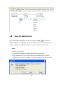
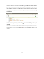
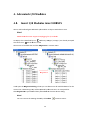
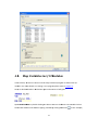
1
U User Manual Adva A antec ch CODE C ESYS S fo or AD DAM M-556 60 CONTENTS 2. 3. 4. 1. Introduction .......................................................................................................... 4 1.1. About This Manual ............................................................................................... 4 1.2. Organization of This Manual................................................................................ 4 Installations ....................................................................................................................... 7 2.1. CODESYS Installation ........................................................................................... 7 2.2. Add‐on Package Installation .............................................................................. 10 2.2.1 First‐time Installation............................................................................ 10 2.2.2 Updating the Package ........................................................................... 13 Create and run a project ................................................................................................. 16 3.1. Start CoDeSys ..................................................................................................... 16 3.2. Create a Project ................................................................................................. 17 3.3. Write a Program ................................................................................................ 19 3.4. Connect to the Target Device ............................................................................ 21 3.5. Run the Application ........................................................................................... 23 Advantech I/O Modules .................................................................................................. 26 4.1. Insert I/O Modules into CODESYS ...................................................................... 26 4.2. Map Variables to I/O Modules .......................................................................... 27 4.3. Support List ........................................................................................................ 29 4.4. Digital Input Modules ........................................................................................ 30 4.5. Digital Output Modules ..................................................................................... 32 4.6. Analog Input Modules ....................................................................................... 34 1 5. 4.7. Analog Output Modules .................................................................................... 35 4.8. Relay Output Modules ....................................................................................... 37 4.9. Counter/Frequency Modules............................................................................. 38 Diagnosis and Troubleshooting ...................................................................................... 44 5.1. Error Notification ............................................................................................... 44 5.2. Log Information ................................................................................................. 44 5.3. Error ID ............................................................................................................... 45 2 Chapter 3 1 1. Introduction 1.1. About This Manual This document describes the use of the CODESYS programming environment and the Wince runtime system for the Advantech ADAM‐5560 series products. Advantech provides add‐on package for CoDeSys which allows developers and end users to connected I/O modules, perform configurations, and simple testing of the I/O. This manual supplies information about how to apply CoDeSys to control Advantech ADAM‐5560, including software installation, writing a new program in CoDeSys to testing ADAM I/O modules. 1.2. Organization of This Manual This user manual is divided into the following sections: Introduction Installations Create and run a project Advantech I/O Modules Diagnosis and Troubleshooting Introduction This section gives the user a basic idea of this manual. 4 Installations This section provides instructions on how to install CoDeSys and Advantech Add‐on Package Create and run a project This section gives the new user a walk‐through in creating a simple program. Advantech I/O Modules This section introduces the detail configuration and mapping variables of Advantech ADAM I/O modules Diagnosis and Troubleshooting This section provides instructions on how to troubleshooting and diagnose operation mistakes or module errors. 5 Chapter 6 2 2. Installlations 1. 2.1 CO ODESYS S Installlation Step p1: Double click and execcute the “Settup_CODESY YSV<Version>.exe” to staart the instaallation assisstant and the en click Nextt to continue e. 7 Step p 2: You will then be prom mpted for thhe installation location. By B default, CooDeSys will instaall to C:\Proggram Files\3S CODESYS, but you can specify the location or foolder name of o yourr choice. Clicck Next to proceed. Step p 3: Select all features an nd then click Next to procceed.. 8 Step p 4: Complette to install CoDeSys C and you’ll see Co oDeSys icon the desktop. Clicck "Finish" to o close the innstallation wizard. w 9 whicch is available on 2.2 2. Ad dd‐on Packag P ge Insta allation n Now w that you haave CoDeSys on your systtem, you’ll want w to do a few steps too install add‐on packkage on yourr environment. 2.2 2.1 Firrst‐tim me Insta allation n Step p 1: Install th he latest verssion of the addd‐on package by double e‐clicking thee executable e “Advvantech ADA AM CODESYS ADD ON.ppackage”. Note! If you get an a error statiing “you musst have administrative rights in orderr to install orr uninstall a package” on n Window 7, you should turn UAC offf. 10 (a) Open User Account A Conttrol Settings by clicking the t Start button , and then clicking Conttrol Panel. In n the search box, type ua ac, and then click Changee User Accou unt Control setttings. N notify pposition, and d then click OK. O (b) Move the sliider to the Never If youu're prompte ed for an admin nistrator passsword or co nfirmation, type t the password or proovide confirmation n. You will ne eed to restarrt your comp puter for UAC to be turneed off. For more inform mation about notification options, ple ease refer to Microsoft w website. Step p 2: When yo ou are asked to choose seetup type, ch hoose the “T Typical setupp” and then click c Nextt. 11 Step p 3: Select all versions an nd then click next. Step p 4: After thee files have in nstalled, youu will see the e completion screen. Clic k "Finish" to o close the installaation wizard. 12 2.2 2.2 Up pdating g the Pa ackage It's h highly recom mmended that you uninsstall the prevvious version package beefore updating and installing ne ew add‐on package, p so yyou can acce ess to Contro ol Panel and uninstall the e prevvious version n package ma anually. Alteernatively, wee can start CoDeSys and perform com mmand Pack kage Manageer from th he men nu (Tools ‐> Package P Manager). Selecct the packagge you want to uninstall and then click “Uninstall”. Clickk "Close" to close c the pacckage managger. Afteer uninstalling the old pacckage successsfully, pleasse refer to First‐time Insttallation. 13 14 Chapter 15 3 3. Create e and ru un a prroject 1. 3.1 Sttart CoD DeSys Starrt CoDeSys byy double‐cliccking the CoD DeSys icon which is available on the deskttop. Alteernatively, yo ou can start the t CoDeSys programmin ng system with Starrt ‐> Program ms ‐> 3S Software ‐> CoD DeSys ‐> COD DESYS V<verssion> Wheen you start the program mming system m the first tim me after firstt installationn on the syste em, you will be asked to choose the default ccollection of settings and d features. Chhoose the “Pro ofessional” and a then click Start to prooceed. Befo ore creating a project, make sure thaat Advantech h ADAM add‐‐on package is installed succcessfully. Cho oose Package Manger fr om the Tools menu: If the Advantech h ADAM add‐‐on package didn’t show w in manager, please refeer to Chapterr 2 and update yourr package. 16 3.2 2. Cre eate a Project P t Step p 1: To createe a new project, choose command New N project from f the Filee menu: In th he New Projeect dialog select Standarrd project in the ‘Templates’ field andd enter a Name and a Location path p for the project p file. PPress OK to confirm. c 17 Step p 2: You will then be prom mpted for chhoosing devices. Choose device Advaantech ADA AM‐5560 WinCE V3 (ADV VANTECH) annd programm ming languag ge Structuredd Text (ST) (dep pend on deveeloper) for PLC_PRG. P Preess OK to ope en the new project. p 18 Step p 3: The project name no ow will appeaar in the title e bar of the CoDeSys C use r interface and the Devices wind dow. 3.3 3. Wrrite a Prrogram m In th he Devices window, w doub ble‐chick PLCC_PRG(PRG) and languag ge editor winndow will op pen. The editor consists of a decla aration part (upper) and a body part (lower), sepparated by a 19 screeen divider. The T declaratiion part show ws line numb bers at the le eft border annd the emb bracing keyw words "VAR" and "END_V VAR" for the variables v decclaration. Declaraation paart Body part D Device window w In th he declaratio on part of the e editor put the cursor behind VAR and press thee Return‐key. A neew empty lin ne will be displayed wherre you enter the declarattion of variabbles. Heree, we write a simple proggram to calc ulate the are ea of triangle e and circle, sso declare i_baase, i_heightt, i_radius wh hich are of tyype INTEGER R, d_area of type REAL: In th he body partt of the PLC_PRG editor pput the curso or in line 1 an nd enter the following lin nes: 20 We need to checck the program for syntaactic errors and a perform command BBuild from d ‐> Build) or press <F11>>: the menu (Build Note! ated in this caase. Error messages will be displayedd in the No code will be genera w whicch is placed at the lowerr part of the user interfacce per default. Messages window 3.4 4. Con nnect to t the T Target Device D In th his section, we w want to discuss how tto connect to o ADAM‐556 60. We need to set the t active ap pplication byy using Devicce editor. It displays d an iccon of proggramming deevice, the current gatewaay and the taarget device with their cconnection sttatus. The Device edito or opens by double clickiing the devicce name in th he device treee. 21 Clickk the Scan ne etwork butto on to search for available e devices in your y local neetwork. You will then n be prompteed for the de evice selectioon. Choose your y target device d and cl ick OK to procceed. In Device editor,, it will show w the connecttion status. Please P checkk that the collored status poin nts are all in green. Note! Meaning of the colored d status poinnt on the gateway and the device: Red: Conneection canno ot be establisshed Green: Con nnection esta ablished Black: Conn nection not defined d 22 3.5 5. Run the Applica A tion We can downloaad the appliccation by perrforming com mmand Login n from m the menu Alt+F8>. You will then be e prompted for choosing login options. (Onlline ‐> Login) or press <A Heree, we choosee “Login with h download”” for the first time and click OK to prooceed. Note! Meaning of login options: “Login with h online chan nge”: Only thhe modified objects will be loaded. “Login with h download””: The compl ete applicatiion will be lo oaded and in itialized completelyy. “Login with hout any chaange”: The laatest modificcations will nnot be loaded d. 23 We run the proggram by perfforming com mand Start from th he menu (De bug ‐> Start)) or ned: In the upper part a ttable shows the presss <F5>. The online view of PLC_PRG will be open watcch variables in applicatio on. In the low wer part you see the code lines as enttered in offliine mod de, supplemeented by the e little inline monitoring windows w beh hind each vaariable, show wing the actual value. Stop p the program m by perform ming commaand Stop from the me enu (Debug ‐> Stop) or press p <Shiift+F8>. g system fro If yo ou want to ch hange into th he offline moode and discconnect the programming p om the ttarget devicee, perform command Loggout fro om the menu u (Online ‐> Logout) or press p <Ctrrl+F8>. 24 Chapter 25 4 4. Advan ntech I/ /O Mod dules 1. 4.1 Inssert I/O O Modu ules into o CODE ESYS We can add and d configure Advantech A I/O O modules as objects in the t device trree. Note! ADAM‐556 60 does NOT support hott plugging for I/O module es. An eempty slot is identified by icon slot shows icon annd entry <Em mpty> (<Empty>). An alreeady occupie ed and the device d namee. Choose one of available slot and click Pluug Device in context men nu. PPlug Device It wiill open the Plug P Device dialog, wherre you can ch hoose one off available deevices for the currrent slot. Thee existing enttry will be reeplaced by th he new one in an occupieed slot. Clickk Plug Device e to proceed d and then prress Close to o close the de evice dialog.. Note! You can remove the exxisting devicee by click Dellete 26 in context c mennu. 4.2 2. Ma ap Varia ables to o I/O Modules M s In th his section, we w want to discuss how tto map variable of progra am to Advanntech I/O mod dules. For mo ore details on creating a new program m please refer to chapteer 3. Heree, we declaree bValue in declaration d ppart and set true t in body part. Opeen Module Ed ditor by double clicking tthe device naame in the device d tree. D Double‐click on the vvariable colu umn and cho oose mappin g variable byy clicking the e button 27 . In this exam mple, we ttry to map th he variable (b bValue) to chhannel 0, so we double‐cclick on the ffirst row of variaable column. It wiill open the Input I Assista ant Dialog, w where you caan choose on ne of availab le devices fo or the current slot. The existingg entry will bbe replaced by b the new one o in an occcupied slot. e to proceed d. Clickk Plug Device 28 Now w, we can download the application a bby performin ng command Login and t hen perform ming com mmand Start.. The channe el‐0 of I/O moodule will be e lit up. Note! If the Advaantech modu ules are correectly configured, it will sh how a green circle icon next to thee device nam me in the devvice tree. If itt shows a red d triangle , see the chapter 5 for f troublesh hooting. 4.3 3. Sup pport List L Advantech provides 21 types of ADAM‐55000 I/O mod dules for varrious applicattions so far. Follo owing table is the I/O mo odules suppoort list. In the e following section, s we w will introduce e I/O mod dules according to their types. t Mod dule Ana alog Input Ana alog Output Name Spec cification Reference ADAM-501 13 3-ch RTD Input Isolated ADAM-501 17 8-ch A AI Isolated ADAM-501 17P 8-ch A AI w/Indepen ndent Input Range R Isolated ADAM-501 17UH 8-ch Ultra High Speed AI (200 0KHz) Isolated ADAM-501 18 7-ch T TC Input Isolated ADAM-501 18P 7-ch T TC Input w/Independent Input Rangee Isolated ADAM-502 24 4-ch A AO Isolated ADAM-505 51 16-ch h DI Non-isolatted 29 Digital Input Digital Output ADAM-5051D 16-ch DI w/LED Non-isolated ADAM-5051S 16-ch Isolated DI w/LED Isolated ADAM-5052 8-ch Isolated DI w/LED Isolated ADAM-5053 32-ch Isolated DI Isolated ADAM-5056 16-ch DO Non-isolated ADAM-5056D 16-ch DO w/LED Non-isolated ADAM-5056S 16-ch Isolated DO w/LED Isolated ADAM-5056SO 16-ch Source Type Isolated DO w/LED Isolated ADAM-5057S 32-ch Isolated DO Isolated Digital I/O ADAM-5055S 16-ch Isolated DI/O w/LED Isolated Relay Output ADAM-5060 6-ch Relay Output Isolated ADAM-5069 8-ch Power Relay Output w/LED Isolated ADAM-5081 4-ch/8-ch High Speed Counter/Frequency Isolated Counter/ Frequency 4.4. Digital Input Modules In this section, we are going to introduce digital input modules. The Module editor opens by double clicking the device name in the device tree. It consists of three tab pages, that is, Status I/O Mapping, Status and Information. Status I/O Mapping: Show the I/O mapping status between variable to module channel. It consists of seven columns. Mapping: The mapping status of each variable. Note! There are two categories of variables: Channel values and Error ID. Channel values: The data type of each channel is in single bit. If the value is “true”, it means that the channel is on; “false” for off. For detailed variable mapping information, see chapter 4.2. 30 Error ID: This variable holds the status of I/O module and its data type is in Word (16 Bits). Get module error ID by mapping the last variable in table. For detailed error ID information, see chapter 5.3. Address: The starting physical address of the variables for this I/O group. The board shown below has 16 digital inputs. This will require either 16 Boolean addresses or 2 Byte addresses. Note! Meaning of address expression: % = Directly Mapped variable I = Physical Input X = Single bit $(N1). $(N2) = The starting address. The first number means the starting byte; the second number means the starting bit. Type: The data type of each variable. Description: The description of each variable. Status: The reserved page. Information: Provide the brief information to current module. 31 4.5 5. Dig gital Ou utput M Moduless In th his section, we w are going to introducee digital outp put modules. The Module editor opens byy double clic king the devvice name in the device trree. It consissts of threee tab pages,, that is, Stattus I/O Mappping, Status and Informa ation. Stattus I/O Mapp ping: Show the I/O mappping status between variable to moduule channel. It conssists of seven n columns. Mapping: The T mappingg status of eaach variable.. Note e! Theree are two cattegories of v ariables: Cha annel valuess and Error ID D. Channel values: The T data typee of each channel is in single bit. Set the value to o “true” for switching on the chhannel; “false e” for switch hing off. For detailed variable mappingg information n, see chapte er 4.2. Error ID: This variable holds thhe status of I/O module and its data type is in Word (16 Bits). Get mod dule error ID D by mappingg the last varriable in tablee. For detaile ed error ID informatiion, see chappter 5.3. 32 Address: The T starting physical p addrress of the vaariables for this t I/O grouup. The board d shown belo ow has 16 digital inputs. This will req quire either 16 1 Boolean aaddresses or 2 Byte addreesses. Note e! Mean ning of addre ess expressioon: % = Directly D Mapp ped variable Q = Physical Outp put X = Siingle bit $(N1)). $(N2) = The starting adddress. The first f number means the sstarting byte; the secon nd number means m the staarting bit. Type: The data d type of each variab le. Description n: The description of eacch variable. Stattus: The reseerved page. Info ormation: Pro ovide the briief informatiion to curren nt module. 33 4.6 6. Ana alog In nput Mo odules In th his section, we w are going to introducee analog inpu ut modules. The Module editor opens byy double clic king the devvice name in the device trree. It consissts of t is, Statu us Configurattion, Status I/O Mapping g, Status andd Informatio on. fourr tab pages, that Stattus Configuraation: Provid de the channnel status pagge for setting g channel ra nges. Dou uble‐click on the value column of the particular ch hannel. Note! For ADAM‐5013, ADAM M‐5017 and ADAM‐5018 8, all channe els are restriccted to the same s channel range and basse on the firsst channel (cch‐0). ping: Show the I/O mappping status between variable to moduule channel. Stattus I/O Mapp Mapping: The T mappingg status of eaach variable.. Note e! Theree are two cattegories of v ariables: Cha annel valuess and Error ID D. Channel values: The T data typee of each channel is in REAL. For detailed variable mappingg information n, see chapte er 4.2. Error ID: This variable holds thhe status of I/O module and its data type is in Word (16 Bits). Get mod dule error ID D by mappingg the last varriable in tablee. For detaile ed error ID informatiion, see chappter 5.3. 34 Address: The T starting physical p addrress of the vaariables for this t I/O grouup. The board d shown belo ow has 8 ana alog inputs. TThis will requ uire 8 DWOR RD addressess. Note e! Mean ning of addre ess expressioon: % = Directly D Mapp ped variable I = Ph hysical Input D = Double D word (32 Bits) $(N) = The startin ng address. Type: The data d type of each variab le. Description n: The description of eacch variable. Stattus: The reseerved page. Info ormation: Pro ovide the briief informatiion for current module. 4.7 7. Ana alog Ou utput M Module es In th his section, we w are going to introducee analog output moduless. The Module editor opens byy double clic king the devvice name in the device trree. It consissts of fourr tab pages, that t is, Statu us Configurattion, Status I/O Mapping g, Status andd Informatio on. Stattus Configuraation: Provid de the channnel status pagge for setting g channel ra nges. Dou uble‐click on the value column of the particular ch hannel. 35 Stattus I/O Mapp ping: Show the I/O mappping status between local variable to module chan nnel. Mapping: The T mappingg status of eaach variable.. Note e! Theree are two cattegories of v ariables: Cha annel valuess and Error ID D. Channel values: The T data typee of each channel is in REAL. For detailed variable mappingg information n, see chapte er 4.2. Error ID: This variable holds thhe status of I/O module and its data type is in Word (16 Bits). Get mod dule error ID D by mappingg the last varriable in tablee. For detaile ed error ID informatiion, see chappter 5.3. Address: The T starting physical p addrress of the vaariables for this t I/O grouup. The board d shown belo ow has 4 ana alog outputs . This will require 4 DWO ORD addressees. Note e! Mean ning of addre ess expressioon: % = Directly D Mapp ped variable Q = Physical Outp put D = Double D word (32 Bits) $(N) = The startin ng address. Type: The data d type of each variab le. Description n: The description of eacch variable. 36 Stattus: The reseerved page. Info ormation: Pro ovide the briief informatiion for current module. 4.8 8. Rellay Outtput Mo odules In th his section, we w are going to introducee relay outpu ut modules. The Module editor opens byy double clic king the devvice name in the device trree. It consissts of threee tab pages,, that is, Stattus I/O Mappping, Status and Informa ation. Stattus I/O Mapp ping: Show the t I/O mappping status between b loca al variable too module cha annel. It co onsists of sevven columns. Mapping: The T mappingg status of eaach variable.. Note e! Theree are two cattegories of v ariables: Cha annel valuess and Error ID D. Channel values: The T data typee of each channel is in single bit. Set the value to o “true” for switching on the chhannel; “false e” for switch hing off. For detailed variable mappingg information n, see chapte er 4.2. Error ID: This variable holds thhe status of I/O module and its data type is in Word (16 Bits). Get mod dule error ID D by mappingg the last varriable in tablee. For detaile ed error ID informatiion, see chappter 5.3. Address: The T starting physical p addrress of the vaariables for this t I/O grouup. The board d shown belo ow has 6 rela ay outputs. TThis will requ uire either 6 Boolean adddresses or 1 Byte address. 37 Note e! Mean ning of addre ess expressioon: % = Directly D Mapp ped variable Q = Physical Outp put X = Siingle bit $(N1)). $(N2) = The starting adddress. The first f number means the sstarting byte; the secon nd number means m the staarting bit. Type: The data d type of each variab le. Description n: The description of eacch variable. Stattus: The reseerved page. Info ormation: Pro ovide the briief informatiion to curren nt module. 4.9 9. Cou unter/F Freque ency Mo odules In th his section, we w are going to introducee counter/fre equency modules. The Module editor opens byy double clic king the devvice name in the device trree. It consissts of fourr tab pages, that t is, Statu us Configurattion, Status I/O Mapping g, Status andd Informatio on. Stattus Configuraation: Provid de the channnel status pagge for setting g channel ra nges. Dou uble‐click on the value column of the particular ch hannel. The module conttains counter chan nnels and DO O/Alarm channels as sho wn image be elow. 38 For counter chan nnels, we offfer five typess of countingg mode (Bi‐d direction, Up//Down, A/B Phasse) for differrent application purposess. The counter will countt up or downn according to t yourr application ns. This countting functionn helps us ob btain the most accurate ddata. Befo ore starting counting, c we e have to set Startup Value, i.e. Initia al value, and the default is 0. The data type off startup valu ue is in DWO ORD. evel minimum signal widdth to reduce e We can also set Digital Filterr (in us) for hhigh or low le noisse spike. Everry counter ch hannel can measure m the frequency of assigned time window and the rangge is from m 0.1Hz to 1M MHz. We can n assigned Frrequency Accquisition Tim me (in ms) too get counter num mber within the t time rangge. For DO/Alarm ch hannels, you u can change the setting by double‐clicking and seelecting an ittem from m the pull‐do own menus: Mode: Seleect "DO" or "Local " Alarm m Latch" Alarm Type e: Select "High" or "Low"", i.e. high alarm or low alarm. a Alarm Limiit: Set alarm limit value. High alarm limit Sendingg High alarm Initial value Sendingg Low alarm 39 m limit Low alarm Alarm Map pping: Selectt counter chaannel numbe er. Stattus I/O Mapp ping: Show the I/O mappping status between local variable to module chan nnel. Mapping: The T mappingg status of eaach variable.. For detailed d variable maapping information, see chapter 4.2. Note e! Theree are three categories of variables: Sttatus variablles, Setting vvariables and d Error ID. Statu us variables: These variabbles are read d‐only and ho old the moduule status. Name Data typpe Information Coun nting Number DWORD The e total countting number.. Coun nting Status Single Biit “true” for starting countingg; “false” for stop. Overflow Status Single Biit “true” for overfflow Latch h Status Single Biit “true” for reach h alarm latchh. Settin ng variables:: These variaables are read‐write. You can change the setting by changging the colu umn value. Name Data typpe Information DO value Single Biit Sett the value to o “true” for sswitching on n the channel; “false” for switching off. 40 Clear to Startup Single Bit Set “true” for set current counting number to startup counting number. Clear Overflow Single Bit Set “true” for clear overflow. Clear Alarm Latch Single Bit Set “true” for clear the alarm latch. For detailed variable mapping information, see chapter 4.2. Error ID: This variable holds the status of I/O module and its data type is in Word (16 Bits). Get module error ID by mapping the last variable in table. For detailed error ID information, see chapter 5.3. Address: The starting physical address of the variables for this I/O group. The board shown below has 4 counter inputs and 4 digital outputs. This will require 4 DWORD addresses for counter channel values and 4 Boolean addresses for digital outputs. Note! Meaning of address expression: % = Directly Mapped variable I = Physical Input Q = Physical Output X = Single bit D = Double word (32 Bits) $(N) = The starting address. Type: The data type of each variable. Description: The description of each variable. 41 42 Chapter 43 5 5. Diagno osis an nd Trou ublesho ooting 1. 5.1 Errror Nottificatio on In ch hapter 4, wee introduce how h to write a program to control Ad dvantech I/O modules. If the Advantech modules are corrrectly configuured, it will show s a green n circle icon he next to th deviice name in the t device trree after perrforming com mmand Login n and Start. I f it shows a red trian ngle , it means that I/O O module enncountered several s errors while runnning. 2. 5.2 Log g Inform mation n We can get log information from f Advanttech CoDeSyys or target machine, m i.e.. ADAM‐5560. In Advantech Co oDeSys devellopment envvironment, double click the device naame in the deviice tree to op pen Device editor. e Selectt the Log diaalog and it will display thee log of the Advantech I/O module. m A logg entry line ccontains the following information: egories: warnnings, errorss, exceptionss, informatio n. The displa ay of Seveerity: There are four cate the entries of eaach category can be switcched on or off o by using the corresponnding button n from m the bar abo ove the listin ng. Each buttton always contains the current c num mber of loggin ngs in th he respectivee category. Timee Stamp: Date and Time. Desccription: Desscription of the t event, foor example “Device not fo ound or not matched." 44 Com mponent: ID and name off the componnent Double click On ttarget machiine, we can also a get erro r ID from Co oDeSys WinCE runtime. In th he ADAM‐5560 environm ment, open ruuntime by do ouble‐clickin ng the runtim me icon whicch is availablle on the low wer‐right cor ner of the de esktop. Get error ID by performing p command c Er rors from the menu (Info o ‐> Errors). 5.3 3. Errror ID Follo owing table is the error ID for I/O moodules. Erro or ID Desscription 0x80000 The module didn’t exist or m match the setting module e. Makke sure that the setting m module matcches for the device that iis being pluggged and che eck your moddule is pluggged in ADAM‐5560 approopriately. 45 0x8001 The system failed to open the module. Please close all programs and reboot. If the system cannot returns to normal condition or the error occurred, please contact Advantech for technical support. 0x8002 The system was unable to complete configuration. Please power‐off the system and plug the module again. If the error occurred, please replace a new module and contact Advantech for technical support. 0x8003 The system failed to read value from the module. Please power‐off the system and plug the module again. If the error occurred, please replace a new module and contact Advantech for technical support. 0x8004 The system failed to write value to the module. Please power‐off the system and plug the module again. If the error occurred, please replace a new module and contact Advantech for technical support. 0x8005 For counter module, the system failed to start/stop counter. Please power‐off the system and plug the module again. If the error occurred, please replace a new module and contact Advantech for technical support. 0x8006 For counter module, the system failed to clear counting value. Please power‐off the system and plug the module again. If the error occurred, please replace a new module and contact Advantech for technical support. 0x8007 For counter module, the system failed to clear overflow flag. Please power‐off the system and plug the module again. If the error occurred, please replace a new module and contact Advantech for technical support. 0x8008 For counter module, the system failed to clear alarm flag. Please power‐off the system and plug the module again. If the error occurred, 46 please replace a new module and contact Advantech for technical support. 47