1
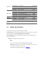
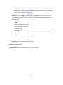
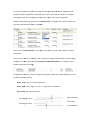
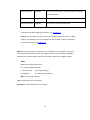
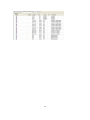
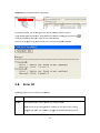
Clear to Startup Single Bit Set “true” for set current counting number to startup counting number. Clear Overflow Single Bit Set “true” for clear overflow. Clear Alarm Latch Single Bit Set “true” for clear the alarm latch. For detailed variable mapping information, see chapter 4.2. Error ID: This variable holds the status of I/O module and its data type is in Word (16 Bits). Get module error ID by mapping the last variable in table. For detailed error ID information, see chapter 5.3. Address: The starting physical address of the variables for this I/O group. The board shown below has 4 counter inputs and 4 digital outputs. This will require 4 DWORD addresses for counter channel values and 4 Boolean addresses for digital outputs. Note!
Meaning of address expression: % = Directly Mapped variable I = Physical Input Q = Physical Output X = Single bit D = Double word (32 Bits) $(N) = The starting address. Type: The data type of each variable. Description: The description of each variable. 41