1
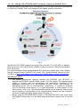
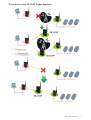
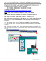
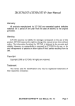
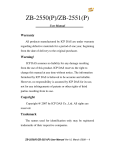
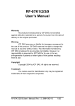
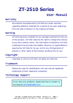
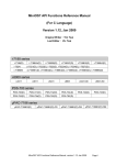
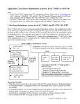
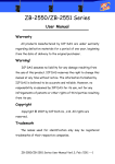
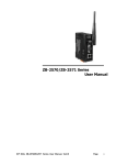
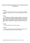
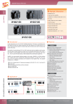
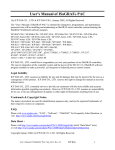
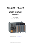
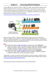
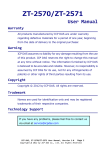
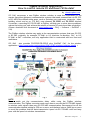
ZigBee Wireless Application:
How to control remote I/O and Read / Write data?
by [email protected]
ICP DAS announces a new ZigBee wireless solution to meet the requirement of the
remote (long/short distance) communication systems that need communicate via RS- 232
or RS- 485 in the difficult wiring areas, such as factories, non-rural areas, reservoirs, cities,
building, school and so on. ICP DAS new released ZB-2550P and ZB-2551P wireless
Converters, converting RS- 232/RS-485 to ZigBee, will help you to solve above problems,
reduce the wiring cost, and achieve the mission of remote I/O control and data acquisition.
(Please download this document at www.icpdas.com > FAQ > Software > ISaGRAF >
110)
The ZigBee wireless solution may apply to the communication systems that uses RS- 232
or RS- 485 originally, for example, PC/HMI to I/O, Machine to Machine, PAC to I/O,
PC/HMI to PAC controllers, and any application that is constructed with one Host and
multi-slave.
ICP DAS
also provides ZB-2550P/ZB-2551P plus ISaGRAF PAC for the wireless
application. ( http://www.icpdas.com/products/GSM_GPR S/wireless/solutions.htm#6 )
Fig-1
NOTE :
Please watch out the communication delay while using the ZigBee wireless
communication. The ZigBee converter needs more time to convert the RS- 232/485 signals
to wireless radio signals than pure RS- 232/485 communication. Recommend to set the
communication timeout setting as 250 ms or more, and the baud rate as 9600 bps or more
to avoid the problem that the data transmission speed via RS- 232/485 could not keep
pace with the speed via wireless transmission.
ICP DAS FAQ-110
1
1.1 : ISaGRAF PAC plus ZB-2550P/ZB-2551P wirelessly connect to I-7000 / I-87K /
ZB- 2000P series I/O modules or other Modbus RTU/ASCII slave devices
In the application of Fig-1 (previous page), we change the I/O data transmission method
from using RS- 485 to wireless (using Host:ZB-2550P + Slave:ZB-2551P ) to connect to I7000 series, RU-87P4/RU-87P8 + I-87K high profile I/O or I-87K4/5/8/9 + I-87K I/O
modules. By the same way, we can also replace the RS- 232/RS-485 by wireless (ZB2550P & ZB-2551P ) to connect to Modbus RTU slave or Modbus ASCII slave devices or
I/O modules.
One WP-8xx7 supports one of its COM2:RS- 485 or COM3: RS- 232/485 to connect to I7000 series, RU-87P4/RU-87P8 + I-87K high profile I/O or I-87K4/5/8/9 + I-87K I/O
modules. (For μPAC- 7186EG, supports COM2: RS- 485; for iP-8xx7, supports one of
COM2: RS- 485 or COM3: RS- 232/485; for VP-25W7 , supports one of COM2: RS- 485 or
COM3 )
For more information about ISaGRAF PAC connecting I-7000 series, RU-87P4/RU-87P8 +
I-87K high profile I/O or I-87K4/5/8/9 + I-87K I/O, please refer to the Chapter 6 of the
“User’s Manual of ISaGRAF PAC”. The file names are:
“user_manual_i_8xx7.pdf” & “user_manual_i_8xx7_appendix.pdf” at
WP-8xx7 CD- ROM: \Napdos\isagraf\wp-8xx7\english_manu\ or
I-8000 CD- ROM: \Napdos\isagraf\8000\english_manu\
or
VP-25W7 CD-ROM: \Napdos\isagraf\vp-25w7\english_manu\ or
http://www.icpdas.com/products/PAC/i-8000/getting_started_manual.htm
Please refer to the following web site for more application figures and detail specifications:
http://www.icpdas.com/products/PAC/i-8000/data%20sheet/data%20sheet.htm
NOTE :
Make sure the driver version of your ISaGRAF PAC is correct for using ZB-2550P / ZB2551P. ( http://www.icpdas.com/products/PAC/i-8000/isagraf-link.htm )
WP-8xx7 / 8xx6
: 1.09 or newer version
VP-25W7
: since the release date (about August, 2009)
iP-8xx7
: 1.03 or newer Version
μPAC- 7186EG
: 1.06 or newer Version
One WP-8xx7 (or VP-25W7) supports up to ten RS- 232/RS-485 ports to connect to
Modbus RTU slave or Modbus ASCII slave devices or I/O. (While iP-8xx7 or μPAC7186EG supports up to 2 ports). For more information about the ISaGRAF PAC using
Modbus RTU/ASCII Master COM ports to connect Modbus RTU slave or Modbus ASCII
slave devices, please refer to the Chapter 8 of the “User’s Manual of ISaGRAF PAC”.
IMPORTANT NOTE:
• The typical transmission distance between the ZB-2550P and ZB-2551P or
between the ZB-2550P and ZB-2000P series I/O is 700 meters. The communication
quality is concerns with the environment and atmospheric conditions. If the
application environment is in the situations of rains, snows, high humidity, or
precipitous terrain such as mountainsides, depressions, or around by obstacles
such as buildings, metal objects, or a signal transmitter, or other objects, or the
noise source…and so on, the communication quality can be reduced, when serious
can be unable to communicate or the communication distance can be shortened.
For those troubles shooting, please refer to Section 1.3 .
• Before using the ZB-2550P/2551P/2510P or ZB-2550/2551/2510, user must setup
the ZigBee configuration. please refer to Section 1.4 for detail setup instructions.
ICP DAS FAQ-110
2
1.2 : PC / HMI plus ZB-2550P/ZB-2551P wirelessly connect to ISaGRAF PACs
In the application of the below Fig-2, the original RS- 232/RS-485 connections between the
PC/HMI and ISaGRAF PACs are changed to be ZigBee wireless connection.
Fig-2
The WP-8xx7/VP-25W7 supports up to five COM ports (RS- 232 or RS- 485) as Modbus
RTU slave ports. The iP-8xx7/μPAC- 7186EG supports up to two COM ports as Modbus
RTU slave ports.
For more information about setting Modbus RTU slave port, please refer to the “Getting
Started” manual of each ISaGRAF PAC model. (The “Getting Started” manual is in the
CD- ROM or http://www.icpdas.com/products/PAC/i-8000/getting_started_manual.htm )
IMPORTANT NOTE:
• The typical transmission distance between the ZB-2550P and ZB-2551P or
between the ZB-2550P and ZB-2000P series I/O is 700 meters. The communication
quality is concerns with the environment and atmospheric conditions. If the
application environment is in the situations of rains, snows, high humidity, or
precipitous terrain such as mountainsides, depressions, or around by obstacles
such as buildings, metal objects, or a signal transmitter, or other objects, or the
noise source…and so on, the communication quality can be reduced, when serious
can be unable to communicate or the communication distance can be shortened.
For those troubles shooting, please refer to Section 1.3 .
• Before using the ZB-2550P/2551P/2510P or ZB-2550/2551/2510, user must setup
the ZigBee configuration. For the detail setup instructions, please refer to Section
1.4 .
ICP DAS FAQ-110
3
1.3 : How to select ZigBee series products
The ZigBee wireless product series by ICP DAS conforms to 2.4G IEEE802.15.4/the
ZigBee standard, the signal frequency is ISM 2.4GHz. The communication quality is
concerns with the environment and atmospheric conditions. If the application environment
is in the situations of rains, snows, high humidity, or precipitous terrain such as
mountainsides, depressions, or around by obstacles such as buildings, metal objects, or a
signal transmitter, or other objects, or the noise source…and so on, the communication
quality can be reduced, when serious can be unable to communicate or the
communication distance can be shortened. Therefore it is necessary to conduct a
preliminary test at the worksite. The problems occurred in every area will not be all the
same, some can be solved by adding the antenna to extend the communication distance;
some can be solved by adding ZigBee Repeater to bypass the disturbance objects(like
radio tower). The following is the product list for user selection.
ZigBee Converter and Repeater:
http://www.icpdas.com/products/GSM_GPR S/wireless/solutions.htm#6
Recommend to choose ZB-2550P, ZB-2551P & ZB-2510P for stronger signals.
Model Number
Description
ZB-2550P
RS- 485/232 to ZigBee Converter (Host), long distance (about 700 m)
ZB-2551P
RS- 485/232 to ZigBee Converter (Slave), long distance (about 700 m)
ZB-2510P
ZigBee Repeater, long distance (about 700 m)
ZB-2550
RS- 485/RS-232 to ZigBee Converter (Host), about 100 m
ZB-2551
RS- 485/RS-232 to ZigBee Converter (Slave), about 100 m
ZB-2510
ZigBee Repeater, about 100 m
Antenna: http://www.icpdas.com/products/GSM_GPR S/wireless/external_antenna.htm
- For ZB-2550P, ZB-2551P and ZB-2510P only to extend the wireless communication
distance. (Larger than 5 dBi at least)
- The ZB-2550/ZB-2551/ZB-2510 cannot use the following antennas. These ZigBee
products have no amplifier inside. The communication become worse if add below
antennas.
(NOTE: Adding an antenna does not guarantee to reach the maximum communication
distance. The communication distance can be shortened, if in the bad environment or
atmospheric conditions. Please conduct a preliminary test at the worksite to confirm the
actual communication state.)
Model Number
Description
ANT-8
Gain: 8 dBi , 1 Km external antenna (Omnidirectional)
ANT-15
Gain: 15 dBi , 9 Km external antenna (Omnidirectional)
ANT-18
Gain: 18 dBi , 12 Km external antenna (Directional)
ANT-21
Gain: 21 dBi , 15 Km external antenna (Directional)
ANT-15YG
Gain: 15 dBi , 9 Km external antenna (Directional)
If there is noise source in the worksite (like the radio tower), user can choose ZB-2510P to
bypass it. (This is not guaranteed for every case. It needs worksite test to confirm.) Please
see the two figures in the next page.
Please refer to the following website for more products information about ZigBee:
http://www.icpdas.com/products/GSM_GPR S/zigbee/zigbee_introduction.htm
ICP DAS FAQ-110
4
The occasions using ZB-2510P (ZigBee Repeater):
ICP DAS FAQ-110
5
1.4 : How to use ZB-255x-Utility to configure the ZB-2550P / ZB-2551P / ZB-2510P
User must complete the product configuration before using the ZB-2550P/2551P/2510P or
ZB-2550/2551/2510 products. Please install ZB-255x-Utility and ZB-257x-Utility to PC.
The Utilities are in the CD- ROM of ZigBee product case:
ZB-255x-Utility: \ZigBee\ZigBee_Converter\ZB_255x\Utility\
ZB-257x-Utility: \ZigBee\ZigBee_Converter\ZB_257x\Utility\
The Utilities download site:
ftp://ftp.icpdas.com/pub/cd/usbcd/napdos/zigbee/zigbee_converter/.
NOTE: Please use ZB-257x-utility to configure ZB-2510 / 2510P repeater.
First, unzip the .zip file then execute the .exe file inside it to install the utility to PC.
Next, power off the ZigBee, set Dip Switch to “ZBSET” , then power it on.
Next, connect the RS- 232 port of PC to the COM0: RS- 232 of ZigBee product by using the
cable CA-0915 or CA-0910N provided in the product case of the ZB-2550/2550P or ZB2551/2551P.
PC --- ZB-2550/ZB-2550P: CA-0915 cable (9-Pin Dsub Male to 9-Pin Dsub Female )
PC --- ZB-2551/ZB-2551P: CA-0910N cable (9-Pin Dsub Female to 9-Pin Dsub Female,
2,3 cross)
Next, run the “ZB-255x-Utility” on PC. Select the favorite langrage and the proper RS- 232
COM port number that PC used to connect to the ZigBee product, and then click “Connect”
and “OK”.
ICP DAS FAQ-110
6
Then, the configuration windows will display. Click “Config” button to configure the ZigBee
product. After finish the configuration, remember to turn off the power of ZigBee, set Dip
Switch to “Run”, and then power it on.
NOTE :
1. Each ZigBee network must include one (and only one) ZigBee Host: ZB-2550P, and
one or more ZigBee Slave: ZB-2551P, and may include some ZigBee Repeaters: ZB2510P. To communicate well, all ZigBee products in the same network must be set to
the same “Pan ID” and the same “RF Channel”.
2. When using ZigBee Slave: ZB-2551P, user must set “Node ID” (one extra setting than
ZB-2550P). The ZB-2551P and ZB-2510P in the same network must be set to the
different “Node ID”.
3. If two or more different ZigBee networks are very close to each others, then user must
set the different “Pan ID” or different “RF Channel” for them, otherwise these different
ZigBee networks can disturb mutually. For example of the Fig-1: There are two ZigBee
networks, one connect to I-7000 and I-87K I/O modules, another connect to Modbus
RTU salve devices. User can set the “Pan ID” as 0xFF01 and the “RF Channel” as 0
for the first ZigBee network, and then set the “Pan ID” as 0xFF01 but the “RF Channel”
as 1 for the second ZigBee network. (Also may set different “PAC ID”, such as one is
0xFF01, another is 0xAA02, but the “RF Channel” all set to be the same, for instance
all are 0.)
Please set the “Operating
Mode” as “Transparent” if the
ZigBee product is for
connecting to I-7000, I-87K
and ZB-2000P series I/O
modules.
Please set the “Operating
Mode” as “Modbus” if the
ZigBee product is for
connecting to Modbus RTU /
Modbus ASCII controllers,
devices or I/O modules.
ICP DAS FAQ-110
7