1
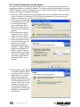
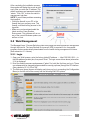
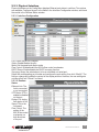
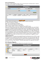
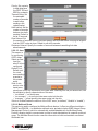
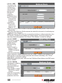
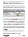
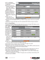
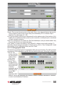
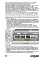
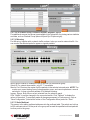
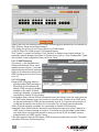
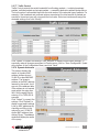
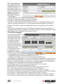
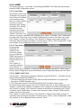
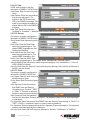
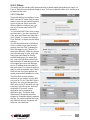
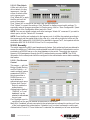
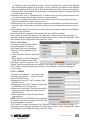
2.2.4 IP Interface
IP Interface on the Config Menu allows users to see the Layer 3 interface status in real time
and configure the interface in the following fields.
Interface: Select the interface to be configured (vlan1 is used by the system).
IP: This is the interface IP address
Mask: This is the interface subnet mask.
MAC: This is the MAC address of this interface.
Status: This is the up/down status of this interface.
DHCP IP Helper Address: This is the IP address of your DHCP server.
Select the corresponding interface and configure the interface parameters, then click “Modify.”
The field you changed will update the associated content in the display window. To save any
changes and make them effective immediately, click “Submit.” Click “Refresh” to refresh the display.
NOTE: There is one important thing to remember regarding DHCP and VLANs: Because each
VLAN is a separate IP subnet, you must configure your DHCP server to deliver IP addresses
that are appropriate for each subnet. With Windows 2000’s DHCP server, you do this by setting
up a separate DHCP realm for each VLAN. Not all DHCP servers have this capability. If your
existing DHCP server works only with flat LANs, you’ll probably have to upgrade to a more
sophisticated package.
SPECIAL NOTE: It is strongly recommended that each interface have its own VLAN; i.e, one
VLAN should not be assigned for two interfaces. Otherwise, it will create confusion while RIP
is enabled. It is also recommended that only one physical port be assigned to the VLAN used
for the L3 interface. When assigning multiple ports to one L3 interface, the L3 traffic will always
go through the the port with lowest ID. The traffic load sharing is not supported in this case.
2.2.5 Router Reports
Router Reports on the Config Menu displays the routing table of the switch.
16
WEB MANAGEMENT