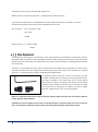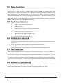
1
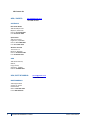
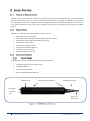
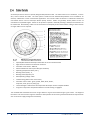
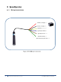
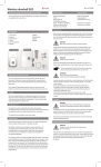
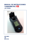
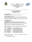
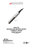
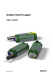
PENTAIR ENVIRONMENTAL SYSTEMS Version 1.1 ...................................................................................................................... 7 .................................................................................................. 8 ........................................................................................................................ 11 ........................................................................................................... 12 Thank you for purchasing the Greenspan Turbidity Sensor Model TS1000. This manual provides a guide to the configuration, operation and maintenance of the sensor to provide long term reliable and accurate monitoring. The TS1000 turbidity probes are designed for monitoring and process applications where turbidity levels of up to 1,000NTU may be encountered. Standard ranges are 100NTU, 400NTU and 1,000NTU. The TS1000 probes, with their integral wiper assembly, are designed for use where bio-fouling or sedimentation build-up is possible. The probes may be submerged to a depth of 100 meters (approx. 330 feet). The TS1000 probe use 90° optics and employs infrared light in accordance with ISO7027. The optical system transmits a beam at a wavelength of 860nm. The effective working area around the sensor is approximately 50mm forward and 50mm circumference. The sensor uses a modulation technique that ensures almost total rejection of ambient light conditions as well as a microprocessor controlled differential sample and hold circuit for enhanced performance particularly at low turbidity levels. Designed for applications where an analogue output is required. The sensor provides both a 4-20mA and a 0-2.5V output. The sensor requires power from a DC source between 8 and 30 Volts. The wiper is activated by connecting the wiper control wire to ground for a brief pulse. The sensor is packaged in an Acetal body, with Double O ring connections for the cable and sensor head. This fully submersible sensor design is rugged and well proven and can withstand the harsh conditions found in remote field applications. Along with this manual, there are several other documents that may assist in the successful configuration and operation of the Greenspan TS1000 Sensor. These should be maintained on file as a permanent reference as to the features, applications and use of the TS1000. Greenspan TS1000 – Specifications Brochure Greenspan TS1000 – Certificate of Conformance Greenspan TS1000 – Quick Start Guide Turbidity probes are assembled and tested in accordance with Greenspan’s ISO 9001 Quality Certified System. Each Sensor is individually manufactured and certified against a traceable Standard. Following calibration the sensors undergo a range of additional control processes to ensure that all specifications are consistent and documented. The instrument is visually inspected, marked and labelled. The complete sensor calibration record is archived for reference, and batch number information is kept on file for statistical analysis. An individual Certificate of Conformance is issued to the customer. All Greenspan Sensors are made to order and are individually calibrated and inspected. This ensures that they leave the factory in a working condition. On receipt, the customer should inspect the packaging and contents for any signs of damage during transportation. The customer should also check that all items on the delivery note have been received. Please contact the factory in case anything is missing or damaged. A full set of documentation including Certificate of Conformance, Quick Start Guide, and User Manual will be provided with all equipment – either in hard copy format or in electronic format on the USB shipped with the goods. Checking the Model Number and Range Before installing your Greenspan TS1000 sensor check the information on the label is correct to confirm you have received the instrument you have ordered. The label will look similar to this. MODEL TS1000 RANGE 0 – xxxx NTU S/N 012345 The customer is advised to keep a record of the serial numbers in case the sensor is lost or the label damage. Greenspan keeps records of all sensors sold including a calibration history. Greenspan warrants all new products against defects in materials and workmanship for 12 months from the date of invoice. Products that prove to be defective during the warranty period will be repaired or replaced at the discretion of Greenspan. Under Greenspan warranty conditions; it is the responsibility of the customer to cover shipping charges back to the factory. Upon repair/replacement Greenspan will cover the return shipping charges to the customer. This warranty does not apply to products or parts thereof which have been altered or repaired outside of the Greenspan factory or other authorised service centre; or products damaged by improper installation or application, or subjected to misuse, abuse neglect or accident. This warranty also excludes items such as reference electrodes and Dissolved Oxygen membranes that may degrade during normal use. Greenspan will not be liable for any incidental or consequential damage or expense incurred by the user due to partial or incomplete operability of its products for any reason whatsoever or due to inaccurate information generated by its products. All Warranty service will be completed as soon possible. If delays are unavoidable customers will be contacted immediately. Any sensor should not be dismantled unless under instruction from Greenspan Technical Service staff. Incorrect handling will void the warranty. The correct choice of sensor and assistance with field installation can be provided by Greenspan and their sales offices. A correct choice of equipment, together with technical advice and field experience should result in long term success in the field. Greenspan Technical Services is dedicated to customer support and provides assistance in the selection, installation, deployment and commissioning of sensors with a full range of consulting services. All Greenspan products are designed, developed and manufactured in Australia and can be supplied at short notice. If for some reason sensors are required to be returned to our factory or your sales representative, please note the model and serial number, Describe the problem, including how and under what conditions the instrument was being used at the time of malfunction. Clean the product and cable. Decontaminate thoroughly if used in toxic or hazardous environment. Carefully pack product in original packaging if possible & include a statement certifying product and cable have been decontaminated with supporting information. Products returned for repair must be accompanied by a completed GRA (Goods Return Advice) form. All sensors returned for service and repair work must be properly decontaminated prior to return. A cleaning charge may be applied to sensors that require further decontamination. Service work will not commence until the quotation has been accepted by the customer. A purchase order for all repair and service work will be required before work is carried out. 1.8 Contact Us ASIA / PACIFIC: [email protected] + 61 1300 797 246 AUSTRALIA New South Wales 268-292 Milperra Rd. Milperra, NSW 2214 Phone: +61 2 9792 0201 Fax: +61 2 9772 2960 Queensland 240 Lavarack Ave Eagle Farm, QLD 4009 Phone: +61 7 3866 7850 Fax: +61 7 3260 1916 Western Australia 70 Cleaver Tce Belmont, WA 6104 Phone: +61 8 9477 1188 Fax: +61 8 9479 6727 ASIA 390 Havelock Road, #04-01, King’s Centre, Singapore. 169662 Phone: +65 6869 8916 USA / REST OF WORLD: [email protected] + 1 407 886 3939 NORTH AMERICA 2395 Apopka Blvd. Apopka, FL 32703 United States Office: 1.407.992.5592 Fax: 1.866.260.0753 6 PENTAIR ENVIRONMENTAL SYSTEMS TS1000 USER MANUAL Turbidity is the measurement that indicates the clarity of water due to fine suspended particles. In the environment, turbidity is often due to clay or silt. These fine particles have the ability to scatter light. The TS1000 has a light source that is projected into the water. A detector measures the light that has been scattered at 90 degrees to the source. As the number of particles increase, more light is scattered and sensed by the detector and the higher the turbidity reading. Applications in which the Greenspan TS1000 can be used include: Monitoring of streams and rivers. Monitoring of water storage bodies including stratification studies. Intermediate and final effluent treatment monitoring. Hydrological run off studies. Ground and bore water analysis. Drinking water filtration efficiency. Industrial process monitoring. Sludge and dredge monitoring. The Greenspan TS Sensor consists of the following primary elements: Turbidity head with lens and integral wiper Acetal Body Material Double O-ring connections Data cable with moulded cable entry Turbidity Head Double O-ring connections Moulded cable entry Lens Wiper Turbidity Lens Power and Data Cable All Greenspan Sensors utilise a specially designed Polyurethane Cable. The cable contains 12 x conductors, 1 x drain wire, and an internal vent tube. The outer jacket is made from UV stabilized Polyurethane and is suitable for all external, underwater or harsh environment applications. This common cable construction is utilized for vented and non-vented sensors and all Greenspan Water Quality Sensors. Cables are generally factory fitted at time of manufacture in specified lengths. Cables can be joined or repaired in the field providing a waterproof connection can be maintained. Alternatively, cables can be terminated in waterproof junction boxes where cabling to other devices or longer cable runs are required. 6 5 4 6 3 2 1 Specially Manufactured Greenspan Cable with 12 cores and Internal Vent High chemical resilience and abrasive resistance Conductor cross section : AWG 24, Electrical Resistance 9 ohm per 100m (per conductor) Operating temperature: 85°C (max.), Bending radius (static) : 6 , Bending radius (dynamic) 12. Max Operating voltage : 250V Jacket Printing (white colour each meter) Conductor colour codes : green, yellow, white, black, brown, turquoise, violet, pink, red, blue, grey Tensile Strength is sufficient to self-suspend the Greenspan Sensor to depths of 300m. Long term creep due to temperature effects or tensile loading is negligible. The moulded cable is fitted to the sensor using a double o ring seal and located using 2 x grub screws. The length of the cable is not critical to the long term calibration and operation of the sensor (provided the electrical requirements such as minimum supply voltage are maintained). The sensor is assembled and calibrated to the required range in accordance with the Greenspan’s ISO9001:2008 Quality System. Sensors are calibrated using AMCO CLEAR® TURBIDITY STANDARD, for ANALITE ISO 7027 PROBES. An extensive range of final calibration and inspection tests are carried out on every sensor. The sensor is visually inspected and packed, ready for despatch. The complete calibration records, sensor history and batch number are placed on file and archived. 8-30VDC (+ve Supply) red Ground (-ve Supply) black Cable Shield yellow/green Signal Output 4-20mA blue Signal Output 0-2.5V brown Signal Ground (Gnd) green Wiper Control (5volt, pull to Gnd) white To maintain high quality control over monitoring programs, it is recommended turbidity calibration is checked every 3-6 months. The TS1000 has no facility to adjust the analogue outputs. If any gain or offset correction is required the factors should be entered into the datalogger or measuring device. Alternatively sensors may be returned to an authorised Greenspan agent for re-calibration. The sensor can be checked by use of known laboratory Turbidity standards. Sensors are calibrated using AMCO CLEAR® TURBIDITY STANDARD, for ANALITE ISO 7027 PROBES. The claimed advantages of these standards are Safe, non-toxic and disposable Easy-to-use/No dilutions or preparations Accurate to 1% lot-to-lot Available in a wide range of values Stable/does not settle out of suspension Guaranteed One Year Shelf Life N.I.S.T. Traceable 1. Remove the sensor from the water, ensure the sensor is clean. Dirty optics could be a key source of calibration errors. 2. Connect the sensor to a DC power source and a meter to measure the sensor output. 3. Place the sensor in clean water so that the sensor face is at least 50mm clear of the bottom of the container. Record the measured output value. 4. The Turbidity value should read Zero +/- 3% of the full scale range of the sensor (eg. 4mA +/- 0.48mA for the current output or 0V +/- 75mV for the voltage output). 5. Place the sensor in a full scale Turbidity solution so that the sensor face is at least 50mm clear of the bottom of the container. Record the measured output value. 6. The Turbidity value should read +/- 3% of the full scale range of the sensor (eg. 20mA +/- 0.48mA for the current output or 2.5V +/- 75mV for the voltage output). 7. This confirms that the sensor electronics has remained stable and no further action should be required if the sensor is within +/- 3 % FS. Most dataloggers or SCADA devices have the ability to enter gain (or multiplier) and offset factors to correct for small changes in the sensor output. If the quick check values are outside allowable tolerances, correction factors can be calculated and entered into the measuring device or used to post process any data recorded. The gain correction can be calculated with the formulaGain correction = (expected reading at Full Scale – expected reading at Zero) / (Reading at Full Scale – Reading at Zero) The offset correction can be calculated with the formula – Offset correction = expected value at Zero – (reading at Zero x Gain correction) E.g. A quick check was done on a TS1000 with the current output connected to an ammeter. The results recorded were 3.28 mA at Zero (clean water) and 18.96 mA at Full scale. Gain correction = (20 – 4) / (18.96 – 3.28) = 16 / 15.68 = 1.0204 Offset correction = 4 – (3.28 x 1.0204) = 0.653 The effectiveness of the wiper in maintaining a clean optical surface will eventually be compromised, the time being dependent on the water under investigation and the number of wiping cycles carried out. We recommend periodic inspection of the wiper pad to determine if the material is deteriorating or is impregnated with material from bio-fouling. The wiper is a consumable item and a spare is provided with each TS1000 sensor along with a hex key to loosen and fasten the wiper set screw. Wiper packs containing two wipers and a hex key are available as a standard accessory. The Greenspan part number is 5TW-001 (pictured below left) 5TW-001 Turbidity Wiper Kit To change the wiper, loosen the set screw in the wiper arm until the wiper assembly can be removed from the wiping shaft. Place a new wiper assembly on the shaft with the set screw aligned squarely with the flat on the wiping shaft. Gently press the wiper arm down until the wiper arm hits the stop on the shaft. The wiper pad should now be compressed to roughly one half its original thickness. Tighten the set screw - do not over tighten. NOTE: It is imperative that the set screw be fastened squarely aligned onto the flat on the shaft otherwise proper operation will be affected. CAUTION: Do not over tighten the set screw or manually attempt to rotate the wiper arm once set onto the shaft. Any attempt to manually rotate the wiper may cause gearbox damage and void the warranty. The sensor should always be completely submerged and positioned such that the possibility of air bubbles, becoming entrapped, which may cause errors, on the sensor face is minimised. The sensor head should be periodically inspected for fouling, and can be cleaned with fresh water and damp cloth. In marine environments crustaceans may need removal at regular intervals. Sensors should generally be installed such that they can be easily and safely removed for cleaning, servicing, replacement of the wiper etc. For environmental applications the sensor can often be mounted inside a section of PVC or steel pipe which enters the water body. The sensor can then be slid down inside the pipe until the sensor head just protrudes into the water body. This provides a high degree of protection for the sensor from environmental (sunlight, heat, flood debris etc) as well as from other influences such as Cattle, vandalism etc. Most sediment transport occurs during storm events and flood conditions. Protection from floating debris damage is an important consideration along with adequate tethering of sensors. Another widespread application of the sensors is to hang the sensors in the water body from a fixed structure or a floating buy or pontoon. Generally in lakes or estuary applications the sensor can hang on its own cable, and easily retrieved for routine servicing. The TS1000 wiper is activated by connecting the wiper control wire to ground. This is usually done by connecting the wiper control wire to a switching device e.g. Relay or FET. The switching device can be controlled by the datalogger or SCADA system. The recommended time to connect the wiper control to ground is between 50ms – 4S. The frequency of wiping will depend on the environmental conditions where the sensor is installed. Waters with high biological activity or high suspended organic or inorganic materials will require more frequent wiping to keep the optics clean. However, excessive wiping will increase power consumption and wear of the wiper. Care should be taken with installation and field servicing to ensure the cable is not subjected to persistent pulling snagging or severe compression. Cyclic loading of the cable should also be avoided through careful sensor deployment. Additional stilling wells or mounting brackets may be required to prevent sensor movement which may cause long term cable movement. Where cable runs are required which may be subject to environmental effects (heat, water movement, sunlight, flood debris etc.) it is advisable to protect the sensor cable inside a slightly larger diameter conduit such as PVC, steel or polyethylene. This also allows the sensor cable to be pulled out – should a sensor change-over be required at the site. Maximum cable runs up to several hundred meters are possible without affecting electrical signals. 1. Edge of river/stream/lake embankment. 2. Side of boat/vessel. 3. Mounted within a stilling well off stream from main flow. 4. Mounted within drainage channels/pipes. 5. Suspended from dam walls or floating pontoon. 6. Sensor anchored to bed of lake/stream. The sensor is anchored or held in position or located so it is not subject to any movement during normal operations. Sensor is protected from direct sunlight to avoid high temperature fluctuations Sensor is protected against high turbulence and possible debris loading during flow events Environmental compatibility should be checked before using the sensors and advice sought from Greenspan if any doubt exists. The sensor utilises some 316 stainless components that are suitable in a majority of situations but care should be taken against possible corrosion in high Chloride, Sulphate or Ferric solutions. The sensor should always be totally immersed under the water to ensure that the sensor is at water temperature and to also avoid any possible anodic/cathodic action taking place on the components at the water-air interface. If using clamps to mount the sensor – these should be of a type that evenly clamps the sensor body without excessive loading that could damage the sensor body. The sensor may be cleaned using a soft cloth, mild detergents and warm water. If the sensor shows signs of marine growth a light biocide can be used to clean and kill any biological growth on the sensor. Measurement Technique 90° Infra-red (ISO7027) Standard ranges available (factory set) 100NTU, 400NTU 1000NTU Resolution 0.1 NTU 0.2 NTU 0.3 NTU Linearity ± 1% ± 1% ± 3% Temperature Coefficient ±0.2%/°C ±0.1%/°C ±0.1%/°C Sensor Outputs 4-20mA and 0-2.5V DC Calibration Standard APS AEPA polymer solutions 100NTU, 400NTU, 1000NTU Cable Type Polyurethane sheathed cable, OD 8mm, aramid reinforced moulded entry, bare wire connection Cable Lengths 10, 20, 30, 50, 100, 150m (32, 65, 100, 165, 325, 490 FT) Non-standard cable lengths Yes (Extra cable moulding time may be required) Power Supply 8-30Vdc (at sensor) Power ESD Protection 2000 volts Current Consumption Sensor 15-40mA while operating Plus extra 30-35mA while wiping Sensor warm up time 10 seconds Wiper arrangement Disposable foam pad on PVC arm. Field replaceable Wiper Control Pull control wire to GND momentarily Pulse time required >50ms, and <4 sec Wiper Time < 8 seconds (1 revolution) Operating Temperature 0-50°C Depth rating (water column) 100m Storage Temperature -5°C - +60°C Weight 500g plus cable weight (665g per 10m length) Dimensions (L x OD) 400.5mm x 47mm (15.77” x 1.85”) Wetted Materials UPVC, acetal, 316 passivated stainless steel, polyurethane, viton