1
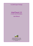
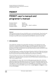
SU-320 & SU-3280
User's Manual
User's Manual
Content
Chapter 1 Product Overview ………………………… 1
Chapter 2 Safety Information ……………………… 1
Chapter 3 Appearance Description ……………… 2
3–1 SU-3280 Front Panel ………………………………………… 2
3–2 SU-3280 Side Panel …………………………………………… 2
3–3 SU-320 front Panel …………………………………………… 3
3-4 SU-320 Side Panel …………………………………………… 3
Chapter 4 Stand-along Operation
………………… 4
4–1 Turn on Page ………………………………………………… 4
4–2 System Mode Selection ……………………………………… 4
4–3 Project List …………………………………………………… 4
4–4 Project Information ………………………………………… 5
4–5 Project Execution & Option ………………………………… 5
4–6 IC Processing ………………………………………………… 6
4–7 IC Status on Socket …………………………………………… 6
Chapter 5 PC Software Operation ………………… 7
5–1 Installation …………………………………………………… 7
5–2 Software Interface …………………………………………… 8
5−2-1 Main Page ……………………………………………… 8
5−2-2 IC Status on Socket …………………………………… 10
5−2-3 Project Manager Pagee ………………………………… 12
5−2-4 Options Setting Page …………………………………… 12
Chapter 6 Tutorial
………………………………………… 17
6–1 PC Software Operation ……………………………………… 17
6–2 Stand-along Operation ……………………………………… 21
User's Manual
Chapter 1 Products Overview
SU-3280/320 is high speed programming for design engineering and small production. It
supports PC-based and Stand-along programming mode which through LCD and keypad download
the file to the inside 3.2GB memory. Moreover, SU-3280/320 adopts modular design. If with the
universal DIP module, you can just use general type adapter on the market for different package.
Chapter 2 Safety Information
All of operation, maintenance and service must adhere to the follow safety notes and
precautions. We shall not assume any responsibility for any unexpected results arising from misuse.
When wind blows on the All of operation, maintenance and service must adhere to the follow
safety notes and precautions. We shall not assume any responsibility for any unexpected results
arising from misuse. vanes of generator, generator creates electricity. Please see the form ula below.
1. Please turn off the power when change the socket module. Be careful to remove the original
socket module. Must pay attention to the direction of insertion. Moreover, check the pins of
connectors situation. Everything is OK, then turn on the power again.
2. Socket module is consumable. The Insertion IC times, delicate operation, and IC surface
cleanliness all affect the quantity of contact between the socket and DUT IC and
programming quantity. When the defect rate increased significantly, we need to consider
whether you replace the socket module.
3. When programming, the programer will provide voltage, if IC misplace or select wrong IC
part no, will damage IC likely.
4. For OTP (one time programming) IC, because can not program again, please must careful
operation.
5. Please pay attention to the master file version and parameter setting and programming
procedure
6. For each new production order, must do on-board test to avoid misuse for the master file.
7. During the mass production, must random inspect IC, included programming file, parameter
setting, security setting, and certain block setting.
8. Please use trained person to operation. Do not use no-experience person to operation.
9. Under the warranty, please do not repair or maintain except we agree.
–1–
User's Manual
10. If have problem, pleas stop programming at once.
11. We will disclaim any responsibility for any loss or damage because of the above misuse.
Chapter 3 Appearance Description
3-1 SU-3280 Front panelr
3-2 SU-3280 Side Panel
–2–
User's Manual
3-3 SU-320 Front panelr
3-4 SU-320 Side Panel
–3–
User's Manual
Chapter 4 Stand-alone Operation
4-1 Turn on Page
Line 1: GANG PROGRAMMER—Product description.
Line 2: Product model, SU-3280-- 4 socket modules, support IC up to 16.
SU-320-- 1 socket module, support IC up to 4.
Line 3: Show the system version and publish date.
Line 4: Press any key to system mode selection page.
4-2 System Mode Selection Page
Ver:1.0
SU-3280
►01.Project Select
02.Link to PC
▲
[▲]/[▼] Up/down
◄
►
►
SATRT
Line 1: Model name and Version.
Line 2: Execute Project select function
Line 3: Via USB to PC, execute remote function.
4-3 Project List
You can save up to 20 project File on SU-3280/320.
–4–
[► ]
Select current item
User's Manual
4-4 Project Information
Line 1: Project name within 16 character. You can save up to 20 project files on the menu withthe
total limit 2GB.
Line 2: Part no. 20 characters at most.
Line 3: The master file check sum, 8-digit HEX.
Line 4: Programming procedure, Erase/Blank Check/Program/Verify/Protect
4-5 Project Execution & Option
Line 1: Part no.
Line 2: 01. Run All - Execute programming procedure. Need to press Start button every time.
Line 3: 02. Auto Run – Execute auto run. Just press Start button once, after that, once new IC
insertion, will start to auto run.
Line 4: Clear counter for the pass quantity.
Line 5: Set the sensitivity of IC insertion for 'Auto Run' function
–5–
User's Manual
4-6 IC Processing
Line 1: IC part no.
Line 2: Check sum, programming procedure.
Line 3: PASS COUNTER, T9~T12 status, T13~T16 status
Line 4: Working Status, T1~T4 status, T5~8 status
4-7 IC Status on Socket
T1~T16( or T1~T4) Status symbol:
E → C → P → V → T: IC process, Erase/Blank Check/Program/Verify/
Protect
〝-〞 Socket Enable
〝 〞 Socket Disable
〝√ 〞 Under Auto Run, new IC place properly
〝?〞 Under Auto Run, new IC pin scan FAIL
〝O〞 PASS, IC still on the socket.
〝o〞 PASS, IC taken off
〝X〞 Process fail, IC still on the socket.
〝x〞 Process fail, IC taken off
–6–
User's Manual
Chapter 5 PC Software
5-1 Installation
Please make sure the Universal IC Writer II and DataBase have been installed.
When instal SU-320 USB drivers, will need to install 2 times. When install SU-3280, will
need to install 5 times. The USB drivers will be placed on the USBDrv automatically. The image
as below. If for SU-320, will only show one Universal IC Writer II.
–7–
User's Manual
5-2 Software Interface
5-2-1 Main Page
Software name and version
Project icon
Option icon
Current project name
Current model name
Project file information
–8–
User's Manual
Counter for record PARR, FAIL and
Total quantity.
Return to 0
Execute programming procedure,
STOP or START.
Execute Run All or Auto Run.
No click- After place ICs well, need
to press the button for each time
programming.Click- No need to
press the button each time.
Stop the Auto Run procedure. The
current procedure will complete
and stop.
Log : Show the current execute status and result.
Clear the log file
–9–
User's Manual
Save the log file
5-2-2 IC Status on Socket
Show each socket IC status. SU-3280 has 4 module adapters. Each module adapters process 4
devices at the same time. 1. UI detect
programmer ready
Under programming. Run All programming Run All programming
successful
status.
2. When Auto Run,
place new IC status.
– 10 –
Fail.
User's Manual
Auto run programming Auto Run
Programming PASS
Programming FAIL
successful. And inform programming fail.
and user can put
and user can put
user to remove IC.
next IC.
next IC.
And inform user to
remove IC.
After Auto Run
After Auto Run
programming finished, programming
user place IC but
finished, user place
without programming
IC but without
and remove IC. It will
programming and
prompt to put IC.
remove IC. It will
The green dotted
prompt to put IC.
line means the last
The red dotted line
time programming
means the last time
pass result, and user
programming fail
place IC but without
result, and user
programming and
place IC but without
remove IC.
programming and
remove IC.
– 11 –
User's Manual
5-2-3 Project Manager Page
You can do add, delete and load file on the page. The maximum projects are up to 20. The
highlight is the current programming project.
Add new project file on the programmer.
Delete the project file on the programmer.
Load the programming project file.
5-2-4 Options Setting Page
– 12 –
User's Manual
[Options->Log Setting]
[Message Box Clearing Selection] :
When [log] line exceed the setting range.
[Auto Clear]: clear the log if exceed the range.
[Auto Clear and Save]: Save and clear the log if exceed the range.
[Limitation of The Number of Rows for Message] :
Setting the range if the log exceed, then clear or save.
[Select Log Save Directory] :
If you set the auto-save log function, the log file will save in this file. If no, the default is
'History\MLOG'.
– 13 –
User's Manual
[Options->SelfTest]
You can click site for self-test or simple LED function. You can see the result on the Main log
or display.
[Options->Information]
You can read the programmer BIOS and serial no. on the page. There two BIOS on SU-3280/320.
[SU BIOS] Main system BIOS, the human-machine interface.
[LP BIOS] Programming BIOS
– 14 –
User's Manual
[Options->BIOS Update]
This is the function of BIOS update, [Display] shows the BIOS version which is came
with the DataBase.
When pressing the Execute, it will update the BIOS to this device.
PS: When you update the BIOS, Led will flash a while. After finishing the update, the device
will reboot automatically.
There's a certain risk for updating. So, do not turn off the power when updating. Otherwise,
the devise would not reboot.
– 15 –
User's Manual
[Options->Auto Run]
[Interval Time] : Set the interval time for Auto Run checking.
[Ignore Insert Detect] : Whether to ignore the Insert Detect result for IC processing.
[Options->SDCard]
[Quick Format] Clear all data on the SDCard
[Backup] Backup the project files (*.lpprj) on the SD card
[Recovery] Restore the project files (*.lpprj) back to the SD card
PS: Please Do not disconnect the programmer(s) during the process!
– 16 –
User's Manual
Chapter 6 Tutorial
6-1 PC Software Operation
<Step1> To Generate project files by single-operation software.
After generate the project file, close the single-operation software. Single-operation or
SU software can be only allowed one type to run at the same time. If both of them are open
at the same time, it will lead to disorder and not work.
<Step 2> Set the programmer to USB, link to PC.
Connect USB cable between PC and the programmer.
– 17 –
User's Manual
<Step3> Open SU software to load the project file
To load the project file, and the loaded file is not accepted to modify any more. If user
wants to modify it, user needs use single-operation software. If the project file on the file,
select it and click Load.
– 18 –
User's Manual
<Step4> Fine-tuning
To perform the Auto Run programming. User can set it following the path:
[Option] → [Auto Run].
<Step5> Start to program
To implement the [START] will begin to do programming. If you want to implement
Auto Run mode, remember to click Auto Run and implement START. If you would like to
finish Auto Run, just implement STOP.
PS. At this moment, the programming driver is using the project file not on the
DataBase.
– 19 –
User's Manual
<Step6> Programming results
Can view programming status and results of each Site on [Site Status]. Or check all of
the PASS / FAIL/Total number in the counter.
PS. When you are using 4 IC socket module, 4 ICs must placed well and start to program.
– 20 –
User's Manual
6-2 Stand-along Operation
Step 1. Repeat 5-1, step 1 to step 3. Close SU Remote software. The programmer will be return to
stand-along mode.
Step 2. Select <Auto Run> or <Run All> for stand-along programming.
Step 3. Place devices on each socket carefully and press <START> to process.
All of devices are complete. You can see the PASS/FAIL status on the LED on the socket module
or on T1~T16 symbol on the LCD.
Remove ICs. The symbol of T1~T16 will show the status in time.
There are 2 ways you can select. One is that to program all of the ICs after all of the ICs
exchanged. Another is asynchronous and concurrent by different socket module.
– 21 –
User's Manual
Step 4. Stop the programing procedure. You can press [◄] to return 'Project Execution &
Option' menu.
Auto Run mode:
Please press <START> button when the first time operation. After that, when you place IC, the
programmer will start auto run procedure.
– 22 –
Doc ume nt No :PME-1 2 1 0 1 9 - V- 1 . 1 ( B)
TEL:+886-2-2999-1860 #15
E-mail:[email protected]
WEB:www.leap.com.tw
www.leaptronix.com