1
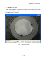
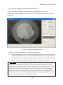
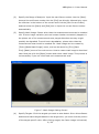
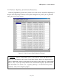
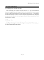
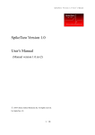
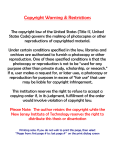
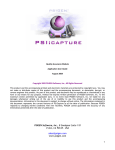
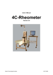
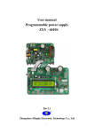
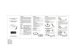
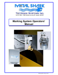
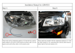
ABDigitizer Version 1.0
User Manual
(Manual Version 1.0.rev2)
© 2012 Chinou Jouhou Shisutemu Inc. All rights reserved.
For ABDigitizer 1.0.
[Table of Contents]
1 Introduction ............................................................................................. 1
2 Requirements ........................................................................................... 1
3 How to use ABDigitizer .............................................................................. 2
3.1 Start the Software ............................................................................... 2
3.2 Open Video File ................................................................................... 3
3.3 Calibration of Length ........................................................................... 5
3.4 Digitizing Settings (Coordinates Detection) ............................................. 7
3.5 Perform Digitizing (Coordinates Detection) ............................................ 11
3.6 Analysis — Trajectory and Heat-Map .................................................... 13
3.6.1 Trajectory ................................................................................... 13
3.6.2 Heat-Map ................................................................................... 15
3.7 Creating Mask Image and Marker Image............................................... 18
3.7.1 Creating Mask Image ................................................................... 18
3.7.2 Creating Marker Image ................................................................. 20
3.8 Analysis from Position Coordinates....................................................... 21
4 Other Operations .................................................................................... 22
4.1 Creating User-Defined Color Bar .......................................................... 22
4.2 Screen Size ...................................................................................... 22
5 Inquiry .................................................................................................. 23
i
ABDigitizer 1.0 User Manual
1 Introduction
ABDigitizer is a digitizing software which analyzes video images of animal behavior
experiments recorded with video camera, automatically retrieves position coordinates
of multiple target animals and output them as time series data.
ABDigitizer has the following features:
Extract multiple target position coordinates independently by color discrimination
method.
Output position coordinates not in pixels but in real length unit.
Split experiment spaces to grids and create heat-map of visit frequency of each
target.
Create trajectory chart of targets, with time markers of constant time interval if
you need.
Output target position coordinates, video with detected positions, heat-map and
trajectory chart.
You can create and save image mask which restricts experiment area.
You can draw any shapes on the heat-map freely.
2 Requirements
This software works with the following environment.
CPU: Intel® Core™ 2 Duo 1.2 GHz or above.
Memory: 2 GB or above. (Processable video size is dependent on the memory
capacity. PC with large amount of memory is recommended.)
OS: Microsoft Windows XP, Windows Vista, Windows 7 (32 bit version)
1 / 23
ABDigitizer 1.0 User Manual
3 How to use ABDigitizer
Usage of ABDigitizer is described below.
3.1 Start the Software
Click [Start]-[All Programs]-[ABDigitizer] from Windows' start menu. Then
ABDigitizer is started and the following screen (called "main screen") is displayed.
Figure 1. Main Screen (immediately after started)
2 / 23
ABDigitizer 1.0 User Manual
3.2 Open Video File
Click [File]-[Open Files]-[AVI] menu of the main screen to read input video file. The
[Video File Selection] screen is displayed. Select video file and push [Open] button.
Readable video file format is the AVI format (*.avi).
Figure 2. Video File Selection Screen
3 / 23
ABDigitizer 1.0 User Manual
After reading video file, video image is displayed in the [Video] tab of the main
screen.
Figure 3. Main Screen after video file was read.
You can play and stop the input video with the buttons placed in the bottom of [Video]
tab. Slide bar can be used to jump to any frame position of the input video. Frame
number is displayed on the right-hand side of the slide bar.
4 / 23
ABDigitizer 1.0 User Manual
3.3 Calibration of Length
Next, perform calibration of length to convert image length (pixels) to physical length
(real length). Click [Digitization]-[Calibration] menu of the main screen, then the
[Calibration] screen is displayed.
Figure 4. Calibration Screen
5 / 23
ABDigitizer 1.0 User Manual
Calibration of length can be performed by the following procedures:
(1)
Specify frame number to calibrate. Input the target frame number into the
[Displayed Frame] box.
(2)
Specify the known length on the calibration screen. Click the start-point of the
known length on the screen, then red line will be drawn. Move your mouse to
the end-point of the known length and click again.
(3)
Input the known length value into the [Length] box in the bottom of the screen.
Length unit can also be specified (default unit is [cm]).
(4)
To erase the drawn red line on the screen and redraw it, click [Reset] button.
(5)
If you succeeded to draw red line correctly, then push [OK] button.
Figure 5. Calibration with the Known Length
6 / 23
ABDigitizer 1.0 User Manual
3.4 Digitizing Settings (Coordinates Detection)
After calibration of length, you must configure digitizing settings. Click
[Digitization]-[Setting] menu of the main screen. The [Digitizing Settings] screen is
displayed.
Figure 6. Digitizing Settings Screen
Configure digitizing settings by the following procedures:
(1)
Specify Background Frame: Specify the background frame which contains no
targets. Background image is used for extracting target animals. If image with
no targets does not exists in the input video, please refer to the following `More
Detail` section and specify the head frame or any frame you want.
More Detail: This software takes difference between all frames (of the range
between frame numbers of [Start] and [End] box) and the background frame
specified in this settings screen to extract targets with improved accuracy. If this
input video has no frame of background-only image, and if you specified frame
between the frame numbers of [Start] and [End] box, then this software can't
extract targets of the specified background frame. In this case, specify the frame
number out of the rage between [Start] and [End].
7 / 23
ABDigitizer 1.0 User Manual
(2)
Specify the Range of Analysis: Input the start frame number into the [Start]
box and the end frame number into the [End] box directly. Alternatively, move
the slide bar in the bottom of the screen and click the [Set Current Frame]
buttons below the [Start] and [End] box to input the current frame number
automatically.
(3)
Specify Mask Image: Places other than the measurement area can be masked
out. If some image variation (such as human shadow movement) happens in
the places out of the measurement area, target detection accuracy might
possibly be degraded. To avoid such degradation, places other than the
measurement area should be masked out. Mask image can be created by
[Tools]-[Make Mask Image] menu, and can be saved by [File]-[Save
Files]-[Mask] menu of the main screen. How to create mask image is described
later. Now just click the [Open] button and select mask image. This process is
not necessary if you not need mask out measurement area.
Figure 7. Mask Image Setting Screen
(4)
Specify Targets: Click the targets you want to auto-detect. Since this software
detects and tracks targets based on the target color, you must click the portion
of the target-specific color. After clicking target, the frame image is binarized,
8 / 23
ABDigitizer 1.0 User Manual
that is, image is converted to black-and-white color (Figure 8). Move and adjust
the slide bar below the [Set] button to turn the target to white and others to
black. After adjusting the slide bar, click the [Set] button. The screen image will
switch to normal and selected target will be displayed in the [Binarize] table
(Figure 9). Mask image will not be displayed. To erase the registered target,
click the left-most column of the target row in the [Binarize] table to highlight
the row, and click [Remove] button.
Figure 8. Clicking the yellow target and adjusting the slide bar
9 / 23
ABDigitizer 1.0 User Manual
Figure 9. Three targets are registered: yellow, blue and pink.
(5)
Complete the Settings: Click the [OK] button.
10 / 23
ABDigitizer 1.0 User Manual
3.5 Perform Digitizing (Coordinates Detection)
Click the [Digitization]-[Execution] menu of the main screen to perform digitizing of
targets. After digitizing finished, showing tab changes from [Video] tab to [Position
Table] tab in the main screen.
Figure 10. Main Screen after Digitizing Finished
Important: Position coordinates shown in the [Position Table] tab assume the
origin to be the bottom-left corner of the frame image. When the target position
can't be detected, position coordinates of the target in that frame will be displayed
as (0.0, 0.0). If you get many frames which can't detect targets, adjust the slide
bar described in the section "3.4 Digitizing Settings " so that the white portion
expands, and perform digitizing again.
11 / 23
ABDigitizer 1.0 User Manual
Switching to the [Video] tab in the main screen, you can review the detected target
positions visually as video image. Detected target positions are indicated as circle with
the color of the specified target.
Figure 11. The [Video] tab of the Main Screen after Digitizing
Detected position coordinates (that is, the contents of the [Position Table] tab) can be
saved to file by clicking [File]-[Save Files]-[Position Table] menu of the main screen.
Saved file format is the CSV format.
Detected position video (that is, the contents of the [Video] tab) can be saved to file
by clicking [File]-[Save Files]-[AVI] menu of the main screen. Saved file format is the
AVI format.
12 / 23
ABDigitizer 1.0 User Manual
3.6 Analysis — Trajectory and Heat-Map
3.6.1 Trajectory
Click [Analysis]-[Trajectory] menu of the main screen to show the detected targets as
trajectory chart. The [Trajectory Settings] screen is displayed.
Figure 12. Trajectory Settings Screen
Setting items are described below:
Range: Configure minimum and maximum value of each axis. Setting [Auto]
checkbox of each axis on, drawing range of that axis will be set automatically.
Line: Configure drawing line width and color.
Time Marker: Draws time markers on the target trajectory with constant time
interval. Setting [Use Time Marker] checkbox on enables this drawing. Configure
time marker's shape, color and time interval.
Click the [OK] button, and you will see trajectory chart in the [Trajectory] tab of the
main screen.
13 / 23
ABDigitizer 1.0 User Manual
Figure 13. Trajectory Chart Screen ([Trajectory] Tab of the Main Screen)
Usage of [Trajectory] tab of the main screen is described below:
The [Target] drop-down list placed in the bottom-left of the chart changes trajectories
of the multiple targets. The up and down button placed in the bottom-right of the chart
changes the size of the time markers, in case you configured to draw them.
This trajectory chart can be saved to file by clicking [File]-[Save Files]-[Trajectory]
menu of the main screen. Saved file format can be selected from Enhanced Metafile
format (*.emf), Bitmap format (*.bmp) or PNG format (*.png).
14 / 23
ABDigitizer 1.0 User Manual
3.6.2 Heat-Map
Click [Analysis]-[Heat Map] menu of the main screen to split frame images to grids,
calculate visit frequency of each grid (in concrete, number of frames the target existed
in the grid) and create heat-map chart. The [Heat Map Settings] screen is displayed.
Figure 14. Heat Map Settings Screen
Setting items of this screen are described below:
Grid: Specify square grid size in pixels which split up the frame images. Grid
shape can only be square.
Color Bar: Specify color bar which is used for creating heat-map. The
[Background Color] label is background color which defaults to blue (Figure 14).
Click the blue label and select background color you want. Also, select color bar
from the drop-down list. User-defined color bar can be loaded. The range of the
color bar can be set automatically by setting [Auto] checkbox on, or input
minimum and maximum values manually by setting [Auto] checkbox off.
Click the [OK] button to see heat-map in the [Heat Map] tab of the main screen.
15 / 23
ABDigitizer 1.0 User Manual
Figure 15. Heat Map Screen ([Heat Map] tab of the main screen)
Usage of [Heap Map] tab of the main screen is described below:
The [Target] drop-down list placed in the bottom-left of the screen will change
the trajectories of multiple targets.
The [Gaussian Filter] slide bar applies Gaussian filter to the heat-map. Adjust the
slice bar and push [Gaussian Apply] button.
Freely drawn pictures can be superimposed on the heat-map as marker. Push the
[Marker Apply] button and select any marker images created by [Tools]-[Draw
Marker] menu of the main screen (this procedure is described for detail in the
subsequent section). The [Marker Apply] button is enabled when marker image
16 / 23
ABDigitizer 1.0 User Manual
was created by [Tools]-[Draw Marker] menu or when marker image was read by
[File]-[Open Files]-[Marker] menu.
Then [Marker Apply] button is enabled after the [Gaussian Apply] button was
clicked. If you don't want to apply Gaussian filter, set [Gaussian filter] slide bar to
the left-most position, push [Gaussian Apply] button and finally push [Marker
Apply] button.
Once the [Marker Apply] button is clicked, this button changes to the [Marker
Remove] button. To erase the marker superimposed on the heat-map, click the
[Marker Remove] button again.
In the bottom-right area of the screen, background color, color bar and these
value ranges used for the heat-map are displayed.
The created heat-map can be saved to file by clicking [File]-[Save Files]-[Heat
Map] menu of the main screen. Saved file format is Bitmap format (*.bmp).
The color bar used for the heat-map can be saved to file as image. Click
[File]-[Save Files]-[Color Bar] menu of the main screen. Saved file format is
Bitmap format (*.bmp).
17 / 23
ABDigitizer 1.0 User Manual
3.7 Creating Mask Image and Marker Image
3.7.1 Creating Mask Image
Click [Tools]-[Make Mask Image] menu of the main screen to draw mask image.
[Draw Mask] screen is displayed.
Figure 16. Draw Mask Screen
Input the frame number into the [Displayed Frame] box which is used for underlying
basis of mask image. The [Draw Mask] screen has five buttons of [Arrow], [Fill],
[Circle], [Square] and [Line].
[Arrow]: This button choices drawn shapes and moves them. Click drawn shape,
move it with your mouse, and click its new position again.
[Fill]: Click the position of the area you want to fill-in with black. Click again to
erase the filled-in area.
[Circle], [Square], [Line]: Click the start-point on the image, move your mouse,
and click the end-point again.
18 / 23
ABDigitizer 1.0 User Manual
Erase the Drawn Shapes: Click [Arrow] button and select shape you want to
erase, and push [Delete] button of your keyboard.
Created mask image can be saved to file by [File]-[Save Files]-[Mask] menu.
Figure 17. Mask Drawing Sample (Only fill-in elimination area in actual)
19 / 23
ABDigitizer 1.0 User Manual
3.7.2 Creating Marker Image
Click [Tools]-[Draw Marker] menu of the main screen to draw marker image. The
[Draw Marker] screen is displayed. In this screen, draw image you want to superimpose
specially on the heat-map such as the start position of the experiment animals.
図 18 Draw Marker Screen
Input the frame number into the [Displayed Frame] box which is used for underlying
basis of marker image. The [Draw Marker] screen has six buttons of [Arrow], [Fill],
[Circle], [Square], [Line] and [Color].
[Arrow]: This button choices drawn shapes and moves them. Click drawn shape,
move it with your mouse, and click its new position again.
[Color]: This button (below the [Square] button) selects drawing color. The
default color is black. Shape buttons such as square use the selected drawing
color. [Fill] button also uses the selected drawing color.
[Fill]: Click the position of the area you want to fill-in with the selected drawing
color. Click again to erase the filled-in area.
20 / 23
ABDigitizer 1.0 User Manual
[Circle], [Square], [Line]: Click the start-point on the image, move your mouse,
and click the end-point again.
Erase the Drawn Shapes: Click [Arrow] button and select shape you want to
erase, and push [Delete] button of your keyboard.
Created marker image can be saved to file by [File]-[Save Files]-[Marker] menu.
Figure 19. Marker Drawing Sample
3.8 Analysis from Position Coordinates
Click [File]-[Open Files]-[Position Text] menu of the main screen to load position
coordinates to the [Position Table] tab which were digitized in the past. Once you loaded
position coordinates, you can create trajectory chart and heat-map.
21 / 23
ABDigitizer 1.0 User Manual
4 Other Operations
4.1 Creating User-Defined Color Bar
Create horizontally long rectangle image with paint tool (e.g. 256 pixels in width and
10 pixels in height). Create the image so that the color changes from the left towards
the right. Create the height direction so that it becomes the same color. In this software,
left side of the color bar is used as minimum value and right side of the color bar is used
as maximum value. Save the color bar image to file as the Bitmap format (either 32-bit
format or 24-bit format).
4.2 Screen Size
Moving your mouse to the bottom-right corner of the main screen, your mouse
pointer shape will change to double arrow. Drag the mouse pointer in that state, and
the size of the main screen will change.
22 / 23
ABDigitizer 1.0 User Manual
5 Inquiry
Please tell us inquiry about ABDigitizer below:
Chinou Jouhou Shisutemu Inc. ABDigitizer Customer Support
TEL: +81-75-321-7300
FAX: +81-75-321-7305
E-mail:
Additional information might be published in our homepage:
ABDigitizer homepage URL:
http://www.abdigitizer.com/en/
23 / 23