1
MITSUBISHI ELECTRIC
Programmable Controller
User's Manual
Q66DA-G,
GX Configurator-DA
(SW2D5C-QDAU-E)
01 05 2008
SH (NA)-080648ENGVersion D
MITSUBISHI ELECTRIC
INDUSTRIAL AUTOMATION
SAFETY PRECAUTIONS
(Always read these instructions before using this equipment.)
Before using this product, please read this manual and the relevant manuals introduced in this manual
carefully and pay full attention to safety to handle the product correctly.
The instructions given in this manual are concerned with this product. For the safety instructions of the
programmable controller system, please read the user's manual for the CPU module to use.
In this manual, the safety instructions are ranked as "DANGER" and "CAUTION".
DANGER
Indicates that incorrect handling may cause hazardous conditions,
resulting in death or severe injury.
CAUTION
Indicates that incorrect handling may cause hazardous conditions,
resulting in medium or slight personal injury or physical damage.
Note that the
CAUTION level may lead to a serious consequence according to the circumstances.
Always follow the instructions of both levels because they are important to personal safety.
Please store this manual in a safe place and make it accessible when required. Always forward it to the end
user.
[DESIGN PRECAUTION]
DANGER
Do not write data into the "system area" of the buffer memory of intelligent function modules.
Also, do not use any "prohibited to use" signals as an output signal to an intelligent function
module from the programmable controller CPU.
Writing data into the "system area" or outputting a signal for "prohibited to use" may cause a
malfunction of the programmable controller system.
CAUTION
Do not bunch the control wires or communication cables with the main circuit or power wires, or
install them close to each other.
They should be installed 100mm(3.9inch) or more from each other.
Not doing so could result in noise that may cause malfunction.
At power ON/OFF, voltage or current may instantaneously be output from the output terminal of
this module. In such case, wait until the analog output becomes stable to start controlling the
external device.
A-1
[INSTALLATION PRECAUTIONS]
CAUTION
Use the programmable controller in an environment that meets the general specifications
contained in the user's manual of the CPU module to use.
Using this programmable controller in an environment outside the range of the general
specifications may cause electric shock, fire, malfunction, and damage to or deterioration of the
product.
While pressing the installation lever located at the bottom of module, insert the module fixing tab
into the fixing hole in the base unit until it stops.
Improper installation may result in malfunction, breakdown or the module coming loose and
dropping.
Securely hold the module with module fixing bracket.
Tighten the screws within the range of specified torque.
If the screws are loose, it may cause the module to fallout, short circuits, or malfunction.
If the screws are tightened too much, it may cause damage to the screw and/or the module,
resulting in fallout, short circuits or malfunction.
Be sure to shut off all phases of the external power supply used by the system before mounting or
removing the module.
Not doing so may cause damage to the module.
In the system where a CPU module supporting the online module change is used and on the
MELSECNET/H remote I/O stations, modules can be replaced online (during energizing).
However, there are some restrictions on replaceable modules and the replacement procedures
are predetermined for each module.
For details, refer to the chapter of the online module change in this manual.
Do not directly touch the conductive area or electronic components of the module.
Doing so may cause malfunction or failure in the module.
A-2
[WIRING PRECAUTIONS]
CAUTION
Always ground the FG terminal for the programmable controller.
There is a risk of electric shock or malfunction.
Tighten the terminal screws within the range of specified torque.
If the terminal screws are loose, it may result in short circuits or malfunction.
If the terminal screws are tightened too much, it may cause damage to the screw and/or the
module, resulting in short circuits or malfunction.
Be careful not to let foreign matter such as sawdust or wire chips get inside the module.
They may cause fires, failure or malfunction.
A-3
[WIRING PRECAUTIONS]
CAUTION
The top surface of the module is covered with protective film to prevent foreign objects such as
cable offcuts from entering the module when wiring.
Do not remove this film until the wiring is complete.
Before operating the system, be sure to remove the film to provide adequate ventilation.
[STARTING AND MAINTENANCE PRECAUTIONS]
CAUTION
Do not disassemble or modify the modules.
Doing so could cause failure, malfunction injury or fire.
Be sure to shut off all phases of the external power supply used by the system before mounting or
removing the module.
Not doing so may cause failure or malfunction of the module.
In the system where a CPU module supporting the online module change is used and on the
MELSECNET/H remote I/O stations, modules can be replaced online (during energizing).
However, there are some restrictions on replaceable modules and the replacement procedures
are predetermined for each module.
For details, refer to the chapter of the online module change in this manual.
Do not install/remove the module to/from the base unit more than 50 times after the first use of the
product. (IEC 61131-2 compliant)
Failure to do so may cause malfunctions.
Do not touch the connector while the power is on. Doing so may cause malfunction.
Switch off all phases of the externally supplied power used in the system when cleaning the
module or retightening the terminal or module fixing screws.
Not doing so may cause failure or malfunction of the module.
If the screws are loose, it may cause the module to fallout, short circuits, or malfunction.
If the screws are tightened too much, it may cause damages to the screws and/or the module,
resulting in the module falling out, short circuits or malfunction.
Always make sure to touch the grounded metal to discharge the electricity charged in the body,
etc., before touching the module.
Failure to do so may cause a failure or malfunctions of the module.
[DISPOSAL PRECAUTIONS]
CAUTION
When disposing of this product, treat it as industrial waste.
A-4
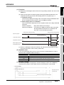
REVISIONS
* The manual number is given on the bottom left of the back cover.
Print Date
*Manual Number
Oct., 2006
SH (NA)-080648ENG-A
First printing
Revision
Jan.,2007
SH (NA)-080648ENG-B
Correction
Section3.2.1, Section4.6
Jan.,2008
SH (NA)-080648ENG-C
Correction
SAFETY PRECAUTIONS, About the Generic Terms and Abbreviations, Section
1.1, Section 2.1, Section 2.3, Section 4.1, Section 4.6, Section 5.2.1, Section
5.2.2, Section 7.3.3, Section 7.3.5, Section 8.1, Appendix 1, Appendix 1.1,
Appendix 1.2, Appendix 1.3
Addition
Section 2.2
May,2008
SH (NA)-080648ENG-D
Correction
SAFETY PRECAUTIONS, Compliance with the EMC and Low Voltage Directives, About the Generic Terms and Abbreviations, Section 2.1, 2.3, 4.1, 4.3,
5.1, 5.2.1, 5.2.2, 5.3.1, 5.3.3, Chapter 7, Section 7.1
Japanese Manual Version SH-080646-E
This manual confers no industrial property rights or any rights of any other kind, nor does it confer any patent
licenses. Mitsubishi Electric Corporation cannot be held responsible for any problems involving industrial
property rights which may occur as a result of using the contents noted in this manual.
2006 MITSUBISHI ELECTRIC CORPORATION
A-5
INTRODUCTION
Thank you for purchasing the MELSEC-Q series programmable controller.
Before using the equipment, please read this manual carefully to develop full familiarity with the functions
and performance of the Q series programmable controller you have purchased, so as to ensure
correct use.
Please forward a copy of this manual to the end user.
CONTENTS
SAFETY PRECAUTIONS .................................................................................................................................A - 1
REVISIONS.......................................................................................................................................................A - 5
INTRODUCTION...............................................................................................................................................A - 6
CONTENTS ......................................................................................................................................................A - 6
ABOUT MANUALS .........................................................................................................................................A - 10
RELATED MANUALS .....................................................................................................................................A - 10
Compliance with the EMC and Low Voltage Directives ..................................................................................A - 10
ABOUT THE GENERIC TERMS AND ABBREVIATIONS ..............................................................................A - 11
PRODUCT STRUCTURE ...............................................................................................................................A - 12
1 OVERVIEW
1.1
1 - 1 to 1 - 2
Features........................................................................................................................................... 1 - 1
2 SYSTEM CONFIGURATION
2 - 1 to 2 - 6
2.1
Applicable Systems ......................................................................................................................... 2 - 1
2.2
Precautions on System Configuration ............................................................................................. 2 - 4
2.3
How to Check the Function Version and Software Version ............................................................. 2 - 5
3 SPECIFICATIONS
3.1
Performance Specifications ............................................................................................................. 3 - 1
3.1.1
3.1.2
3.1.3
3.1.4
3.2
A-6
Analog output HOLD/CLEAR function .................................................................................. 3 - 11
Analog output test during programmable controller CPU STOP .......................................... 3 - 13
Warning output function........................................................................................................ 3 - 14
Rate control function............................................................................................................. 3 - 16
Scaling function .................................................................................................................... 3 - 18
I/O Signals for the Programmable Controller CPU ........................................................................ 3 - 21
3.3.1
3.3.2
3.4
Performance specifications list ............................................................................................... 3 - 1
I/O conversion characteristics ................................................................................................ 3 - 2
Accuracy ................................................................................................................................. 3 - 9
Conversion speed................................................................................................................... 3 - 9
Function List .................................................................................................................................. 3 - 10
3.2.1
3.2.2
3.2.3
3.2.4
3.2.5
3.3
3 - 1 to 3 - 38
List of I/O signals .................................................................................................................. 3 - 21
Details of I/O signals............................................................................................................. 3 - 22
Buffer Memory ............................................................................................................................... 3 - 27
3.4.1
3.4.2
3.4.3
3.4.4
3.4.5
3.4.6
3.4.7
3.4.8
3.4.9
3.4.10
3.4.11
3.4.12
3.4.13
3.4.14
3.4.15
3.4.16
3.4.17
3.4.18
3.4.19
Buffer memory assignment................................................................................................... 3 - 27
D/A conversion enable/disable setting (Un\G0).................................................................... 3 - 30
CH digital values (Un\G1 to Un\G6) ..................................................................................... 3 - 30
CH[ ]set value check codes (Un\G11 to Un\G16)................................................................. 3 - 31
Error codes (Un\G19) ........................................................................................................... 3 - 31
Setting range (Un\G20, Un\G21) .......................................................................................... 3 - 32
Offset/gain setting mode and offset/gain specification (Un\G22, Un\G23) ........................... 3 - 32
Offset/gain adjustment value specification (Un\G24) ........................................................... 3 - 33
Offset/gain range setting (Un\G25)....................................................................................... 3 - 33
Rate control enable/disable setting (Un\G46)....................................................................... 3 - 34
Warning output setting (Un\G47).......................................................................................... 3 - 34
Warning output flag (Un\G48)............................................................................................... 3 - 35
Scaling enable/disable setting (Un\G53) .............................................................................. 3 - 35
Scaling upper/lower limit value (Un\G54 to Un\G65)............................................................ 3 - 36
CH increase/decrease digital limit values (Un\G70 to Un\G81)............................................ 3 - 36
CH warning output upper limit value/lower limit value (Un\G86 to Un\G97)......................... 3 - 36
Mode switching setting (Un\G158, Un\G159) ....................................................................... 3 - 37
Save data classification setting (Un\G200)........................................................................... 3 - 37
Factory default setting and user range settings offset/gain values
(Un\G202 to Un\G225) ......................................................................................................... 3 - 38
4 SETUP AND PROCEDURES BEFORE OPERATION
4 - 1 to 4 - 15
4.1
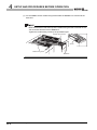
Handling Precautions...................................................................................................................... 4 - 1
4.2
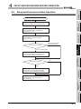
Setup and Procedures before Operation ......................................................................................... 4 - 3
4.3
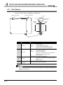
Part Names...................................................................................................................................... 4 - 4
4.4
Wiring............................................................................................................................................... 4 - 6
4.4.1
4.4.2
Wiring precautions.................................................................................................................. 4 - 6
External wiring ....................................................................................................................... 4 - 7
4.5
Intelligent Function Module Switch Setting ...................................................................................... 4 - 8
4.6
Offset/Gain Settings....................................................................................................................... 4 - 11
5 UTILITY PACKAGE (GX Configurator-DA)
5 - 1 to 5 - 34
5.1
Utility Package Functions ................................................................................................................ 5 - 1
5.2
Installing and Uninstalling the Utility Package ................................................................................. 5 - 2
5.2.1
5.2.2
5.3
Handling precautions.............................................................................................................. 5 - 2
Operating environment ........................................................................................................... 5 - 4
Utility Package Operation ................................................................................................................ 5 - 6
5.3.1
5.3.2
5.3.3
Common utility package operations ....................................................................................... 5 - 6
Operation overview................................................................................................................. 5 - 9
Starting the Intelligent function module utility ....................................................................... 5 - 11
5.4
Initial Setting .................................................................................................................................. 5 - 15
5.5
Auto Refresh Setting...................................................................................................................... 5 - 17
5.6
Monitoring/Test .............................................................................................................................. 5 - 20
5.6.1
5.6.2
5.6.3
Monitor/test screen ............................................................................................................... 5 - 20
Offset/gain setting operation................................................................................................. 5 - 23
Confirmation of Conversion Characteristic ........................................................................... 5 - 25
A-7
5.6.4
Pass data.............................................................................................................................. 5 - 27
5.7
FB Conversion of Initial Setting/Auto Refresh Setting ................................................................... 5 - 29
5.8
Usage of FB ................................................................................................................................... 5 - 31
5.8.1
5.8.2
5.8.3
Outline .................................................................................................................................. 5 - 31
Paste an FB to a Sequence Program ................................................................................... 5 - 33
Convert (Compile) a Sequence Program.............................................................................. 5 - 34
6 PROGRAMMING
6 - 1 to 6 - 18
6.1
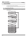
Programming Procedure.................................................................................................................. 6 - 1
6.2
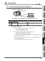
For Use in Normal System Configuration ........................................................................................ 6 - 2
6.2.1
6.2.2
6.2.3
6.3
Before creating a program ...................................................................................................... 6 - 3
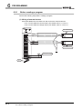
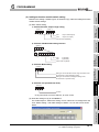
Program example using the utility package ............................................................................ 6 - 5
Programming example without using the utility package........................................................ 6 - 8
For Use on Remote I/O Network ................................................................................................... 6 - 10
6.3.1
6.3.2
Program example using the utility package .......................................................................... 6 - 12
Program example without using the utility package.............................................................. 6 - 15
7 ONLINE MODULE CHANGE
7 - 1 to 7 - 36
7.1
Online Module Change Conditions .................................................................................................. 7 - 2
7.2
Online Module Change Operations ................................................................................................. 7 - 3
7.3
Online Module Change Procedure .................................................................................................. 7 - 4
7.3.1
7.3.2
7.3.3
7.3.4
7.3.5
7.3.6
When industrial shipment setting is used and initial setting was made with
GX Configurator-DA ............................................................................................................... 7 - 4
When industrial shipment setting is used and initial setting was made with
sequence program.................................................................................................................. 7 - 9
When user range setting is used and initial setting was made with GX Configurator-DA
(other system is available) .................................................................................................... 7 - 14
When user range setting is used and initial setting was made with GX Configurator-DA
(other system is unavailable) ................................................................................................ 7 - 19
When user range setting is used and initial setting was made with sequence program
(other system is available) .................................................................................................... 7 - 25
When user range setting is used and initial setting was made with sequence program
(other system is unavailable) ................................................................................................ 7 - 30
7.4
Range Reference Table................................................................................................................. 7 - 35
7.5
Precautions for Online Module Change ......................................................................................... 7 - 36
8 TROUBLESHOOTING
8 - 1 to 8 - 7
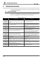
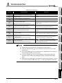
8.1
Error Code List................................................................................................................................. 8 - 1
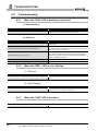
8.2
Troubleshooting ............................................................................................................................... 8 - 3
8.2.1
8.2.2
8.2.3
8.2.4
8.2.5
8.2.6
A-8
When the "RUN" LED is flashing or turned off........................................................................ 8 - 3
When the "ERR." LED is on or flashing .................................................................................. 8 - 3
When the "ALM" LED is turned on.......................................................................................... 8 - 3
When an analog output value is not output ............................................................................ 8 - 4
When the analog value is not within the reference accuracy of the theoretical value ............ 8 - 5
When analog output value is not “HOLD” ............................................................................... 8 - 5
8.2.7
APPENDIX
Checking the Q66DA-G status using GX Developer system monitor..................................... 8 - 6
App- 1 to App - 10
Appendix 1 Dedicated Instruction List and Available Devices..................................................................App- 1
Appendix 1.1 G(P).OFFGAN ................................................................................................................App- 2
Appendix 1.2 G(P).OGLOAD ................................................................................................................App- 4
Appendix 1.3 G(P).OGSTOR................................................................................................................App- 7
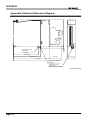
Appendix 2 External Dimension Diagram............................................................................................... App- 10
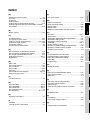
INDEX
Index - 1 Index - 2
A-9
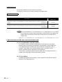
ABOUT MANUALS
The following manuals are also related to this product.
If necessary, order them by quoting the details in the tables below.
RELATED MANUALS
Manual Number
Manual Name
(Model Code)
GX Developer Version 8 Operating Manual
Describes the methods of using GX Developer to create a program and print out, monitor, and debug the
program.
(Sold separately)
GX Developer Version 8 Operating Manual (Function Block)
Describes the methods of using GX Developer to create a function block and print out the function block.
(Sold separately)
SH-080373E
(13JU41)
SH-080376E
(13JU44)
Remark
îR
If you would like to obtain a manual individually, printed matters are available separately. Order the manual by quoting the manual number on the table above
(model code).
COMPLIANCE WITH THE EMC AND LOW VOLTAGE DIRECTIVES
(1) For programmable controller system
To configure a system meeting the requirements of the EMC and Low Voltage
Directives when incorporating the Mitsubishi programmable controller (EMC and
Low Voltage Directives compliant) into other machinery or equipment, refer to
Chapter 9 "EMC AND LOW VOLTAGE DIRECTIVES" of the QCPU User's
Manual (Hardware Design, Maintenance and Inspection).
The CE mark, indicating compliance with the EMC and Low Voltage Directives, is
printed on the rating plate of the programmable controller.
(2) For the product
No additional measures are necessary for the compliance of this product with the
EMC and Low Voltage Directives.
A - 10
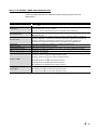
ABOUT THE GENERIC TERMS AND ABBREVIATIONS
Unless otherwise specified, this manual uses the following general terms and
abbreviations.
Abbreviation/general terms
DOS/V personal computer
Description of the abbreviation/general terms
IBM PC/AT or compatible computer with DOS/V.
Generic product name for the SWnD5C-GPPW-E, SWnD5C-GPPW-EA, SWnD5C-GPPW-EV and
GX Developer
SWnD5C-GPPW-EVA. ("n" is 4 or greater.)
"-A" and "-V" denote volume license product and upgraded product respectively.
GX Configurator-DA
Generic term for digital-analog conversion module setting and monitor tool GX Configurator-DA
(SW2D5C-QDAU-E).
Generic term for Q00JCPU, Q00CPU, Q01CPU, Q02CPU, Q02HCPU, Q06HCPU, Q12HCPU,
QCPU (Q mode)
Q25HCPU, Q02PHCPU, Q06PHCPU, Q12PHCPU, Q25PHCPU, Q12PRHCPU, Q25PRHCPU,
Q02UCPU, Q03UDCPU, Q04UDHCPU, Q06UDHCPU, Q13UDHCPU, Q26UDHCPU,
Q03UDECPU, Q04UDEHCPU, Q06UDEHCPU, Q13UDEHCPU and Q26UDEHCPU.
Process CPU
Generic term for Q02PHCPU, Q06PHCPU, Q12PHCPU and Q25PHCPU.
Personal computer
Generic term for DOS/V personal computer
Industrial shipment setting
Generic term for analog input ranges 0 to 5V, 1 to 5V, -10 to 10V, 0 to 20mA and 4 to 20mA.
FB
Abbreviation of function block.
Generic term for the following:
Windows Vista
Microsoft
Windows Vista
Home Basic Operating System,
Microsoft
Windows Vista
Home Premium Operating System,
Microsoft
Windows Vista
Business Operating System,
Microsoft
Windows Vista
Ultimate Operating System,
Microsoft
Windows Vista
Enterprise Operating System
Generic term for the following:
Windows
XP
Microsoft
Windows
XP Professional Operating System,
Microsoft
Windows
XP Home Edition Operating System
A - 11
PRODUCT STRUCTURE
The product structure of this product is given in the table below.
Model code
Product name
Quantity
Q66DA-G
Q66DA-G Model Channel Isolated Digital-Analog Converter module
SW2D5C-QDAU-E
GX Configurator-DA Version 2(1-license product)
(CD-ROM)
1
SW2D5C-QDAU-EA
GX Configurator-DA Version 2(Multiple-license product)
(CD-ROM)
1
A - 12
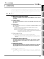
1
OVERVIEW
(1) Multi-channel analog input is available.
By using a single Q66DA-G, analog voltage or current outputs of 6 points (6 channels)
are available.
(2) Channel isolated
The module is isolated between the channels and between the external supply power
and channels.
3
SPECIFICATIONS
Features
*1: Accuracy attained at the ambient temperature when offset/gain setting has been made
*2: Accuracy per temperature change of 1°C
Example) Accuracy when the ambient temperature varies from 25°C to 30°C
0.1% (reference accuracy) + 0.008%/°C (temperature coefficient)
(temperature variation difference) = 0.14%
5°C
(4) Output range switching
The output range*1 switching can be set easily from GX Developer.
*1: The output range indicates the offset/gain setting type. Besides the generally often used output
ranges available as defaults, the user can make offset/gain settings and use the values. (Refer to
Section 4.5)
(4) Analog output HOLD/CLEAR function
This function is used to set whether the analog output value will be held or cleared
when the CPU module is in a STOP status or when a stop error occurs. (Refer to
Section 3.2.1)
5
UTILITY PACKAGE
(GX CONFIGURATORDA)
The reference accuracy*1 is as high as +0.1% and the temperature coefficient*2 is as
high as -80ppm/°C.
SETUP AND
PROCEDURES
BEFORE OPERATION
4
(3) High accuracy
6
PROGRAMMING
1.1
2
SYSTEM
CONFIGURATION
This User's Manual describes the specifications, handling and programming methods for
the Q66DA-G type channel isolated digital-analog converter module (hereinafter referred
to as the Q66DA-G) which are used in conjunction with MELSEC-Q series CPU module
(hereinafter referred to as the programmable controller CPU).
OVERVIEW
1
7
(5) Output monitor function
The analog output value output by D/A conversion is reconverted into a digital value
within the Q66DA-G and the result is stored into the buffer memory as an output
monitor value.
(6) Changing the resolution mode
The resolution mode can be changed according to the application, and digital value
resolution settings of 1/4000, 1/12000 or 1/16000 can be selected. (Refer to Section
4.5)
1.1 Features
1-1
ONLINE MODULE
CHANGE
1
OVERVIEW
8
TROUBLESHOOTING
1
1
OVERVIEW
(7) Warning output function
A warning is output if a digital input value falls outside the setting range. (Refer to
Section 3.2.4.)
(8) Rate control function
The increase and decrease in analog output values per 6ms *1 can be limited,
preventing rapid change of the values. (Refer to Section 3.2.4.)
*1 6ms is the conversion cycle per channel.
(9) Scaling function
The digital input value range can be changed to any given range between –32000 and
32000, and digital values within the range are converted to analog values. (Refer to
Section 3.2.5.)
(10)Online module change
The module can be changed without the system being stopped.
Further, the dedicated instruction (G(P). OGLOAD, G(P). OGSTOR), write to the
buffer memory, or turning ON the Y signal enables "inheritance of offset/gain settings
to the new Q66DA-G replacing the old one changed online" and "transfer of offset/
gain settings to the other Q66DA-G mounted on the other slot". (These apply to the
modules of the same model.) (Refer to Chapter 7.)
(11)Offset/gain setting
GX Configurator-DA, dedicated instruction (G(P). OFFGAN) or mode switching
setting allows a shift to the offset/gain setting mode easily. (Refer to Section 4.6.)
(12)Easy settings using the utility package
A utility package is sold separately (GX Configurator-DA).
The utility package is not a required item, however, it is useful for on-screen setting of
the intelligent function module parameters (initial setting/auto refresh setting). In
addition, FB*1 can be generated automatically from the intelligent function module
parameters that have been set up and used in a sequence program. (Refer to
Chapter 5.)
*1: FB is the function for making a circuit block used in a sequence program repeatedly a part (FB) to
use it in the sequence program.
This function can improve the efficiency of program development and minimize program bugs to
improve program qualities.
For the details of FB, refer to "GX Developer Version 8 Operating Manual (Function Block)."
1-2
1.1 Features
2
SYSTEM CONFIGURATION
1
OVERVIEW
SYSTEM CONFIGURATION
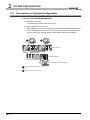
This chapter explains the system configuration of the Q66DA-G.
2
SYSTEM
CONFIGURATION
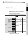
Applicable Systems
(1) Applicable modules and base units, and No. of modules
(a) When mounted with a CPU module
The table below shows the CPU modules and base units applicable to the
Q66DA-G and quantities for each CPU model.
Depending on the combination with other modules or the number of mounted
modules, power supply capacity may be insufficient.
Pay attention to the power supply capacity before mounting modules, and if the
power supply capacity is insufficient, change the combination of the modules.
Applicable CPU module
CPU type
No. of modCPU model
Q00JCPU
Basic model QCPU
Base unit*2
Q00CPU
Q01CPU
ules*1
Main base unit
Extension base
unit
Up to 16
Up to 24
Q02HCPU
Q06HCPU
UTILITY PACKAGE
(GX CONFIGURATORDA)
model QCPU
Up to 64
Q12HCPU
Q25HCPU
Q02PHCPU
Process CPU
Q06PHCPU
Q12PHCPU
Up to 64
6
Q25PHCPU
controller CPU
Redundant CPU
Q12PRHCPU
Q25PRHCPU
Q02UCPU
Up to 53
PROGRAMMING
Programmable
Up to 36
Q03UDCPU
Q04UDHCPU
Q06UDHCPU
QCPU
7
Q13UDHCPU
Q26UDHCPU
Q03UDECPU
Up to 64
ONLINE MODULE
CHANGE
Universal model
Q04UDEHCPU
Q06UDEHCPU
Q13UDEHCPU
Q26UDEHCPU
Safety CPU
C Controller module
QS001CPU
Q06CCPU-V
Q06CCPU-V-B
4
5
Q02CPU
High Performance
3
SPECIFICATIONS
This section describes the applicable systems.
SETUP AND
PROCEDURES
BEFORE OPERATION
2.1
8
N/A
Up to 64
: Applicable,
: N/A
*1 Limited within the range of I/O points for the CPU module.
*2 Can be installed to any I/O slot of a base unit.
2.1 Applicable Systems
2-1
TROUBLESHOOTING
2
2
SYSTEM CONFIGURATION
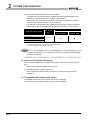
(b) Mounting to a MELSECNET/H remote I/O station
The table below shows the network modules and base units applicable to the
Q66DA-G and quantities for each network module model.
Depending on the combination with other modules or the number of mounted
modules, power supply capacity may be insufficient.
Pay attention to the power supply capacity before mounting modules, and if the
power supply capacity is insufficient, change the combination of the modules.
Applicable network module
Base unit*2
No. of mod*1
ules
Main base unit of
Extension base unit of
remote I/O station
remote I/O station
QJ72LP25-25
QJ72LP25G
QJ72LP25GE
Up to 64
QJ72BR15
: Applicable,
: N/A
*1 Limited within the range of I/O points for the network module.
*2 Can be installed to any I/O slot of a base unit.
Remark
The Basic model QCPU or C Controller module cannot create the MELSECNET/
H remote I/O network.
(2) Support of the multiple CPU system
When using the Q66DA-G in a multiple CPU system, refer to the following manual
first.
• QCPU User's Manual (Multiple CPU System)
(a) Intelligent function module parameters
Write intelligent function module parameters to only the control CPU of the
Q66DA-G.
(3) Compatibility with online module change
The Q66DA-G supports online module change (hot swapping).
For procedures of the online module change, refer to Chapter7.
2-2
2.1 Applicable Systems
SYSTEM CONFIGURATION
1
OVERVIEW
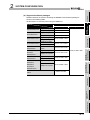
(4) Supported software packages
Software Version
GX Developer
GX Configurator-DA
Version 7 or later
Multiple CPU system
Version 8 or later
Q02/Q02H/Q06H/
Single CPU system
Version 4 or later
Q12H/Q25HCPU
Multiple CPU system
Version 6 or later
Q12PH/Q25PHCPU
Multiple CPU system
Single CPU system
Multiple CPU system
Q12PRH/
Redundant CPU
Q25PRHCPU
Q02U/Q03UD/
system
Q04UDH/
Q06UDHCPU
Version 8.68W or later
Version 7.10L or later
Version 8.45X or later
Single CPU system
Multiple CPU system
Q13UDH/
Single CPU system
Q26UDHCPU
Multiple CPU system
Q03UDE/
Single CPU system
3
SPECIFICATIONS
Q02PH/Q06PHCPU
Single CPU system
Version 2.06G or later
Version 8.48A or later
Version 8.62Q or later
5
Q13UDEH/
Multiple CPU system
UTILITY PACKAGE
(GX CONFIGURATORDA)
Q04UDEH/
Q06UDEH/
Version 8.68W or later
Q26UDEHCPU
Version 6 or later
6
PROGRAMMING
station
7
ONLINE MODULE
CHANGE
If installed in a MELSECNET/H remote I/O
4
SETUP AND
PROCEDURES
BEFORE OPERATION
Single CPU system
Q00J/Q00/Q01CPU
2
SYSTEM
CONFIGURATION
Relation between the system containing the Q66DA-G and software package is
shown in the following table.
GX Developer is necessary when using the Q66DA-G.
8
TROUBLESHOOTING
2
2.1 Applicable Systems
2-3
2
SYSTEM CONFIGURATION
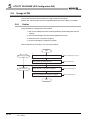
2.2
Precautions on System Configuration
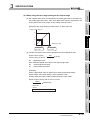
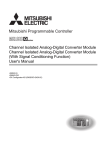
(1) For Use with Q12PRH/Q25PRHCPU
(a) Dedicated instruction
The dedicated instruction cannnot be used.
(b) GX Configurator-DA connection
GX Configurator-DA cannot be used when accessing the Q12PRH/Q25PRHCPU
via an intelligent function module on an extension base unit from GX Developer.
Connect a personal computer with a communication path indicated below.
1
2
Main base unit
Extension base unit
(GX Configurator-DA cannot be used.)
2-4
1
Direct connection to use the CPU
2
Direct connection to the CPU
2.2 Precautions on System Configuration
2
SYSTEM CONFIGURATION
1
This section describes how to check the function version of the Q66DA-G and the GX
Configuration-DA software version.
OVERVIEW
How to Check the Function Version and Software Version
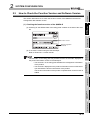
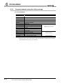
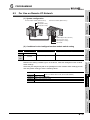
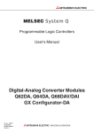
(a) Checking at "the SERIAL field of the rating plate" located on the side of the module
SYSTEM
CONFIGURATION
2
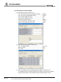
(1) Checking the function version of the Q66DA-G
SPECIFICATIONS
3
Function version
080810
Relevant regulation
standards
UTILITY PACKAGE
(GX CONFIGURATORDA)
5
6
PROGRAMMING
The serial No. on the rating plate may be different from the serial No. displayed on
the product information screen of GX Developer.
• The serial No. on the rating plate indicates the management information
of the product.
• The serial No. displayed on the product information screen of GX Developer indicates the function information of the product.
The function information of the product is updated when a new function is
added.
SETUP AND
PROCEDURES
BEFORE OPERATION
4
(b) To check the version using the GX Developer
Refer to Section 8.2.7 of this manual.
ONLINE MODULE
CHANGE
7
8
TROUBLESHOOTING
2.3
2.3 How to Check the Function Version and Software Version
2-5
2
SYSTEM CONFIGURATION
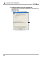
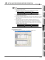
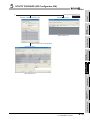
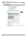
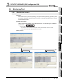
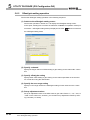
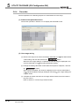
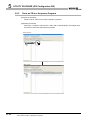
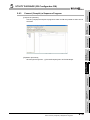
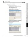
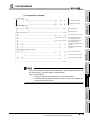
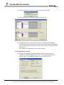
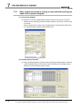
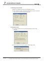
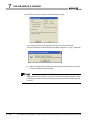
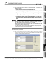
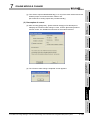
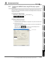
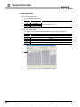
(2) Checking the software version of GX Configuration-DA
The software version of GX Configurator-DA can be checked in GX Developer's "Productinformation" screen.
[Operating procedure]
GX Developer
[Help]
[Product information]
Software version
(In the case of GX Developer Version 8)
2-6
2.3 How to Check the Function Version and Software Version
3
1
Performance Specifications
2
SYSTEM CONFIGURATION
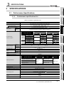
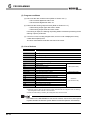
Performance specifications list
Table3.1 Performance specifications list
Item
Specifications
Number of analog outputs
6 points (6 channels)
16-bit signed binary (normal resolution mode:-4096 to 4095
high resolution mode: -12288 to 12287, -16384 to 16383)
Digital input
Voltage
-12 to 12VDC (External load resistance: 1k to 1M )
Current
0 to 20mADC (External load resistance: 0 to 600 )
0 to 22mADC (External load resistance: Please refer to Note 3)
Normal resolution mode
Analog output range
Digital input
value
0 to 5V
I/O characteristics
maximum resolution
Voltage
2.5mV
User range setting 3
0.375mV
0 to 20mA
5 A
0 to 4000
4 to 20mA
Reference
accuracy *1
0.1% (Voltage:
Temperature
coefficient *2
-12000 to 12000
0 to 12000
4 A
-4000 to 4000
1.5 A
-12000 to 12000
10mV, Current:
80ppm/
(0.008%/
Maximum
resolution
0.416mV
0.333mV
0.625mV
0.400mV
0.210mV
1.66 A
1.33 A
0.95 A
20 A)
)
6ms/ channels
Conversion speed
Absolute maximum
output
-16000 to 16000
0.75mV
-4000 to 4000
User range setting 1
Accuracy (Accuracy
relative to maximum
analog output value)
0 to 12000
1.0mV
-10 to 10V
User range setting 2
Current
Digital input
value
1.25mV
0 to 4000
1 to 5V
High resolution mode
Maximum
resolution
Voltage
13V
Current
23mA
Maximum number of writes to flash
memory
Available
Specific isolated area
Between external supply power and
analog output cannel
External wiring connection system
Applicable wire size
External device connection connector
Dielectric withstand
oltage
Isolation method
Between the output terminal and programmable controller power supply
Between analog output channels
Number of I/O occupied points
Insulation
resistance
500VAC rms, 1min
Transformer
isolation
1000VAC rms, 1min
500VDC
10M
or more
500VAC rms, 1min
16 points (I/O assignment: Intelligent 16 points)
40-pin connector
0.3 mm2 (AWG #22)
A6CON4 (Sold separately)
24VDC, +20%, -15%
External supply power
5
6
Up to 50,000 times
Output short-circuit protection
Isolation specifications
4
8
Ripple, spike within 500 mV p-p
Inrush current: 4.8A, within 400 s
0.62A
Weight
0.22kg
3.1 Performance Specifications
3.1.1 Performance specifications list
TROUBLESHOOTING
0.22A
Internal current consumption
(5 VDC)
7
ONLINE MODULE
CHANGE
Analog output
3
16-bit signed binary (-32768 to 32767)
UTILITY PACKAGE
(GX CONFIGURATOR-DA)
Using scaling function
SPECIFICATIONS
3.1.1
SETUP AND PROCEDURES BEFORE
OPERATION
3.1
OVERVIEW
SPECIFICATIONS
PROGRAMMING
3
SPECIFICATIONS
3-1
3
SPECIFICATIONS
*1: Accuracy of offset/gain setting at ambient temperature
Q66DA-G needs to be powered on 30 minutes prior to operation for compliance to the specification
(accuracy).
*2: Accuracy per temperature change of 1 °C
Example: Accuracy when temperature changes from 25 to 30 °C
0.1% (Reference accuracy) + 0.008%/ °C (temperature coefficient) 5 °C (temperature
change difference) = 0.14%
*3: The following indicates the external load resistance when output current is 20mA or more.
22mA
Output
current
20mA
500
600
External load resistance
Remark
See the user's manual for the CPU module being used for the general specifications for the Q66DA-G.
3.1.2
I/O conversion characteristics
I/O conversion characteristics are used for converting the digital value written from the programmable controller CPU to an analog output value (voltage or current output), and represented by inclined straight lines when offset and gain values are included.
Offset value
The offset value is the analog output value (voltage or current) when the digital input value
set from the programmable controller CPU is 0.
Gain value
The gain value is the analog output value (voltage or current) when the digital input value
set from the programmable controller CPU is
4000 (in normal resolution mode)
12000 (when 1 to 5V, 0 to 5V, 4 to 20 mA, 0 to 20 mA or the user range setting1 to 3 is
selected in high resolution mode),
16000 (when -10 to 10V is selected in high resolution mode).
3-2
3.1 Performance Specifications
3.1.2 I/O conversion characteristics
3
SPECIFICATIONS
1
2
SYSTEM CONFIGURATION
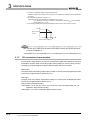
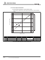
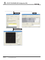
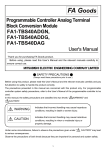
(a) Voltage output characteristic in normal resolution mode
Fig.3.1 shows a graph of the voltage output characteristic in normal resolution
mode.
OVERVIEW
(1) Voltage output characteristic
10
3)
3
1
2)
0
-5
4
SETUP AND PROCEDURES BEFORE
OPERATION
1)
SPECIFICATIONS
Practical analog output range
Analog output value(V)
5
5
-4096 -4000
-2000
-96
0
2000
UTILITY PACKAGE
(GX CONFIGURATOR-DA)
-10
4000 4095
Digital input value
Output range setting
Offset value
Gain value
1)
1 to 5 V
1V
5V
2)
0 to 5 V
0V
5V
3)
-10 to 10 V
0V
10 V
-
User range setting 2
*1
*1
-
User range setting 3
*2
*2
Digital input value
Maximum resolution
0 to 4000
1.0 mV
1.25 mV
2.5 mV
-4000 to 4000
6
PROGRAMMING
Number
0.75 mV
0.375 mV
7
ONLINE MODULE
CHANGE
Fig.3.1 Voltage output characteristic in normal resolution mode
TROUBLESHOOTING
8
3.1 Performance Specifications
3.1.2 I/O conversion characteristics
3-3
3
SPECIFICATIONS
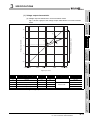
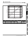
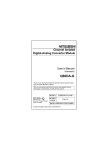
(b) Voltage output characteristic in high resolution mode
Fig.3.2 shows a graph of the voltage output characteristic in high resolution mode.
12
10
3)
Practical analog output range
Analog output value(V)
5
1)
1
2)
0
-5
-10
-12
-16384 -16000
-8000
-288
0
8000
12000 1600016383
12287
Digital input value
Number
Output range setting
Offset value
Gain value
1)
1 to 5 V
1V
5V
2)
0 to 5 V
0V
5V
3)
–10 to 10 V
0V
10 V
-
User range setting2
*1
*1
-
User range setting3
*2
*2
Digital input value
0 to 12000
-16000 to 16000
-12000 to 12000
Fig.3.2 Voltage output characteristic in high resolution mode
3-4
3.1 Performance Specifications
3.1.2 I/O conversion characteristics
Maximum resolution
0.333 mV
0.416 mV
0.625 mV
0.400 mV
0.210 mV
SPECIFICATIONS
Normal resolution mode
High resolution mode
3.0V
5.0V
<Value of A>
Normal resolution mode
High resolution mode
1.5V
2.6V
SYSTEM CONFIGURATION
SPECIFICATIONS
3
4
5
UTILITY PACKAGE
(GX CONFIGURATOR-DA)
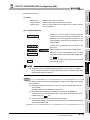
(4) Set the offset/gain values for the user range setting 3 *2 within a range in
which the following conditions are satisfied.
(a) Setting range is from -0.5 to 6 V.
(b) { (Gain value) - (Offset value) } > A
2
SETUP AND PROCEDURES BEFORE
OPERATION
(1) Set within the digital input range and analog output range for each output
range.
If these ranges are exceeded, the maximum resolution and accuracy may not
fall within the performance specifications. (Avoid using the dotted line area
shown in Figures 3.1 and 3.2.)
(2) In user range setting 2, the maximum and minimum output values are 6V and
-6V respectively. Obtain these values as follows using the gain and offset values.
Maximum analog output value = Gain value
Minimum analog output value = (Offset value - (Gain value - Offset value))
If a maximum or minimum value exceeds the output range, use user range
setting 3.
(3) Set the offset/gain values for the user range setting 2 *1 within a range in
which the following conditions are satisfied.
(a) Setting range is from -12 to 12 V.
(b) { (Gain value) - (Offset value) } > A
<Value of A>
OVERVIEW
1
PROGRAMMING
6
ONLINE MODULE
CHANGE
7
8
TROUBLESHOOTING
3
3.1 Performance Specifications
3.1.2 I/O conversion characteristics
3-5
3
SPECIFICATIONS
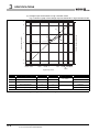
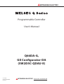
(2) Current output characteristic
(a) Current output characteristic in normal resolution mode
Fig.3.3 shows a graph of the current output characteristic in normal resolution
mode.
20
Practical analog output range
Analog output value(mA)
15
10
1)
2)
5
4
0
-96 0
4000 4095
2000
Digital input value
Number
Output range setting
Offset value
Gain value
1)
4 to 20 mA
4 mA
20 mA
2)
0 to 20 mA
0 mA
20 mA
-
User range setting1
*1
*1
Digital input value
0 to 4000
–4000 to 4000
Fig.3.3 Current output characteristic in normal resolution mode
3-6
3.1 Performance Specifications
3.1.2 I/O conversion characteristics
Maximum resolution
4 A
5 A
1.5 A
3
SPECIFICATIONS
(b) Current output characteristic in high resolution mode
Fig.3.4 shows a graph of the current output characteristic in high resolution mode.
22
15
1)
2)
3
SPECIFICATIONS
10
5
SYSTEM CONFIGURATION
2
Practical analog output range
4
SETUP AND PROCEDURES BEFORE
OPERATION
4
0
-288 0
6000
12000 12287
5
Digital input value
Number
Output range setting
Offset value
Gain value
1)
4 to 20 mA
4 mA
20 mA
2)
0 to 20 mA
0 mA
20 mA
-
User range setting1
*1
*1
Digital input value
Maximum resolution
0 to 12000
–12000 to 12000
1.33
A
1.66
A
0.95
A
UTILITY PACKAGE
(GX CONFIGURATOR-DA)
Analog output value(mA)
20
OVERVIEW
1
6
PROGRAMMING
Fig.3.4 Current output characteristic in high resolution mode
ONLINE MODULE
CHANGE
7
TROUBLESHOOTING
8
3.1 Performance Specifications
3.1.2 I/O conversion characteristics
3-7
3
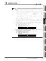
SPECIFICATIONS
(1) Set within the digital input range and analog output range for each output
range.
If these ranges are exceeded, the maximum resolution and accuracy may not
fall within the performance specifications. (Avoid using the dotted line area
shown in Figures 3.3 and 3.4.)
(2) Set the offset/gain values for the user range setting 1 *1 within a range in
which the following conditions are satisfied.
(a) Setting range is from 0 to 22 mA
(b) { (Gain value) - (Offset value) } > A
<Value of A>
3-8
Normal resolution mode
High resolution mode
6.0mA
11.5mA
3.1 Performance Specifications
3.1.2 I/O conversion characteristics
SPECIFICATIONS
1
The temperature coefficient is the accuracy per temperature variation of 1 .
The reference accuracy is the accuracy relative to the maximum value of the analog output value.
Even if the offset/gain setting or analog output range is changed to change the output
characteristic, the reference accuracy and temperature coefficient do not vary and are
kept within the ranges given in the performance specifications.
to 30
0.1% (reference accuracy) + 0.008%/
(temperature coefficient)
(difference in temperature variation) = 0.14%
Conversion speed
The conversion speed for the Q66DA-G is "6ms the number of conversion enabled
channels".
By setting the unused channels to D/A conversion disabled (Refer to Section 3.4.2), the
conversion speed can be increased.
4
UTILITY PACKAGE
(GX CONFIGURATOR-DA)
5
PROGRAMMING
6
7
ONLINE MODULE
CHANGE
3.1.4
3
5
SPECIFICATIONS
Example) Accuracy when the temperature varies from 25
2
SYSTEM CONFIGURATION
The reference accuracy is the accuracy at the ambient temperature for offset/gain setting.
OVERVIEW
Accuracy
SETUP AND PROCEDURES BEFORE
OPERATION
3.1.3
8
TROUBLESHOOTING
3
3.1 Performance Specifications
3.1.3 Accuracy
3-9
3
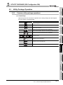
SPECIFICATIONS
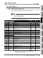
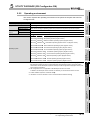
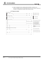
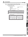
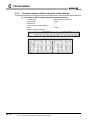
3.2
Function List
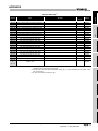
Table 3.2 shows the function of the Q66DA-G.
Table3.2 Function list
Item
Function
D/A conversion enable/
• Specifies whether to enable or disable the D/A conversion for each channel.
disable function
• Disabling D/A conversion of unused channels can increase the conversion speed.
Reference section
Section 3.4.2
• Specifies whether to output the D/A converted value or output the offset value for
D/A output enable/dis-
each channel.
able function
• Regardless of the output enable/disable setting, the conversion speed is “6ms x
Analog output HOLD/
• The output analog value can be retained when the programmable controller CPU is
Section 3.3.1
number of conversion-enabled channels”.
CLEAR function
placed in the STOP status or when an error occurs.
Analog output test during
programmable controller
CPU STOP
Warning output function
• When the CH
output enable/disable flag is forced ON during programmable con-
troller CPU STOP, the D/A converted analog value is output.
• A warning is output if a digital input value falls outside the setting range.
Section 3.2.1
Section 3.2.2
Section 3.2.3
• The increase and decrease in analog output values per conversion cycle of one staRate control function
tion (6ms) can be limited.
Section 3.2.4
• Using this function prevents rapid change of analog output values.
• The resolution mode can be changed according to the application, and a resolution
setting can be selected from 1/4000, 1/12000 and 1/16000.
Resolution mode
• The resolution mode setting is applicable to all channels in block.
• Refer to Section 3.1.1 for the digital input values and maximum resolution in normal
Section 3.1.1
Section 4.5
resolution mode and high resolution mode.
• The input range of digital values can be changed to any given range between -32000
Scaling function
and 32000.
Online module change
3 - 10
• The module can be changed without the system being stopped.
3.2 Function List
Section 3.2.5
Chapter 7
3
SPECIFICATIONS
1
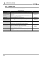
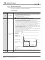
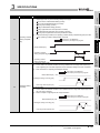
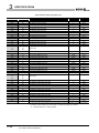
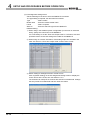
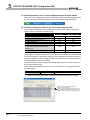
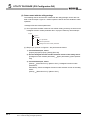
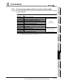
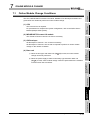
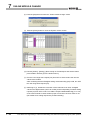
(2) Make the setting in the HOLD/CLEAR setting (Refer to Section4.5 (1).) of the intelligent function module switch.
(3) Depending on combinations of the HOLD/CLEAR setting, D/A conversion enable/disable setting (Un\G0), and CH output enable/disable flag (Y1 to Y6), the analog output status varies as shown in Table 3.3.
D/A conversion enable/disCH
Execution
status
output enable/
Enable
disable flags (Y1 to Y6)
HOLD/CLEAR setting
HOLD
CLEAR
Analog output status when programmable controller
Outputs analog values converted
CPU is RUN
from digital values.*2
Analog output status when programmable controller
CPU is STOP
Analog output status when a programmable controller
CPU stop error occurs
Analog output status when a watchdog timer error*1
Enable or disable
HOLD or CLEAR
HOLD or CLEAR
Offset
0 V/0 mA
4
Disable
Hold
Offset
Offset
0 V/0 mA
Hold
Offset
Offset
0 V/0 mA
0 V/0 mA
0 V/0 mA
0 V/0 mA
0 V/0 mA
*1 This occurs when program operations are not completed within the scheduled time due to a hardware problem of the Q66DA-G. When a watchdog timer error occurs, module READY (X0) turns
OFF and the Q66DA-G RUN LED turns off.
*2 The rate control function and the scaling function are operable.
5
PROGRAMMING
6
ONLINE MODULE
CHANGE
7
8
TROUBLESHOOTING
occurs in Q66DA-G
Disable
Enable
able setting ( Un\G0)
SETUP AND PROCEDURES BEFORE
OPERATION
Setting
combination
3
SPECIFICATIONS
Table3.3 Analog output status combination list
2
SYSTEM CONFIGURATION
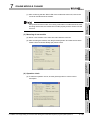
(1) For the case where the programmable controller CPU is placed in STOP or in a stop
error status, whether to hold (HOLD) or clear (CLEAR) the analog output value can be
set.
OVERVIEW
Analog output HOLD/CLEAR function
UTILITY PACKAGE
(GX CONFIGURATOR-DA)
3.2.1
3.2 Function List
3.2.1 Analog output HOLD/CLEAR function
3 - 11
3
SPECIFICATIONS
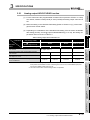
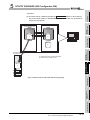
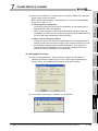
The following conditions should be satisfied when the analog output HOLD/
CLEAR function is used on a MELSECNET/H remote I/O station.
• The master module of function version D or later and the remote I/O module of function version D or later are required.
• Validate the station unit block guarantee of the send side cyclic data.
• The setting for holding the Q66DA-G output in the case of a link error
must be made in the "Error time output mode in the I/O assignment setting". (Refer to Section 4.5 (2).) The HOLD/CLEAR setting by the intelligent function module switch is invalid. This setting is validated on a permodule basis, and is not made on a per-channel basis. Therefore, to
make the output status at a stop error or STOP of the programmable controller CPU matched with the output status at a link error, set the same
.HOLD/CLEAR setting to all channels. (Refer to the table below.)
Error time output mode
Hold analog output
Clear analog output
(Output offset value)
HOLD/CLEAR setting
(Same setting to all channels)
Hold
HOLD
Clear
CLEAR
For the station unit block guarantee of the cyclic data, refer to the Q Corresponding MELSECNET/H Network System Reference Manual (Remote I/O Network).
3 - 12
3.2 Function List
3.2.1 Analog output HOLD/CLEAR function
3
SPECIFICATIONS
1
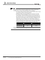
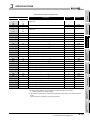
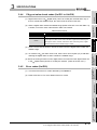
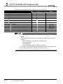
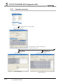
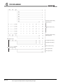
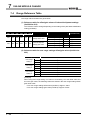
(a) Set D/A conversion enable/disable setting (Un\G0) of the channel to be tested to
enable.
(b) Switch the operating condition setting request (Y9) from OFF to ON to OFF.
(c) Sets the output enable/disable flag (Y1 to Y6) for the channel to be tested to
enable (OFF
ON).
(d) Write digital values equivalent to analog values that are to be output to the CH
digital value (Un\G1 to Un\G6).
Table3.4 List of analog output test
output enable/disable flags (Y1 to Y6)
Analog output test
Disable
Allowed
Not allowed
4
Disable
Enable
disable
Not allowed *1
*1 Perform the analog output test after changing the D/A conversion enable/disable setting (Un\G0) to
enable.
SETUP AND PROCEDURES BEFORE
OPERATION
CH
Enable
Enable
5
When the digital input value is set to be written to the CH digital value (Un\G1 to
Un\G6) from the CPU device at the automatic refresh setting of GX ConfiguratorDA, write digital input value to the CPU device where the setting is performed. The
automatic refresh can be performed while the programmable controller CPU is in
STOP.
PROGRAMMING
6
7
ONLINE MODULE
CHANGE
combination
D/A conversion enable/disable setting (Un\G0)
3
8
TROUBLESHOOTING
Setting
2
SYSTEM CONFIGURATION
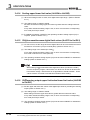
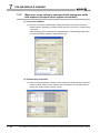
(2) To conduct an analog output test, perform the following on Device test of GX Developer or on the relevant test screens of Configurator-DA (Refer to Section 5.6.1.).
SPECIFICATIONS
(1) While the programmable controller CPU is in STOP, an analog output test as shown in
Table 3.4 can be performed.
OVERVIEW
Analog output test during programmable controller CPU STOP
UTILITY PACKAGE
(GX CONFIGURATOR-DA)
3.2.2
3.2 Function List
3.2.2 Analog output test during programmable controller CPU STOP
3 - 13
3
SPECIFICATIONS
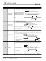
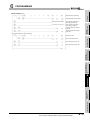
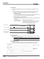
3.2.3
Warning output function
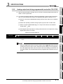
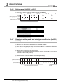
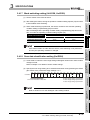
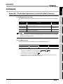
(1) If the digitat input value is equal to or greater than the warning output upper limit value
or equal to or less than the warning output lower limit value, the warning output flag
(Un\G48) and warning output signal (XE) turn ON to give a warning.
The warning is output for the D/A conversion enabled channel only.
(2) The analog output value of waring occurrence is the value converted from the digital
value at the warning output upper limit value or warning output lower limit value.
(3) The warning output flag (Un\G48) and warning output signal (XE) turn OFF when the
operating condition setting request (Y9) or warning output clear request (YE) turns
ON.
(4) To use this function, the following settings are required for each setting.
• Enable the warning output function: Warning output setting (Un\G47)
• Set the warning output upper and lower limit values: CH
lower limit values (Un\G86 to Un\G97)
warning output upper/
Digital input value
Digital input value
Analog output value
32000
Warning output
upper limit value
Warning output
lower limit value
-32000
CH1 warning output flag
(upper limit value)(Un\G48,b0)
OFF
CH1 warning output flag
(lower limit value)(Un\G48,b1)
OFF
Warning output signal(XE)
OFF
Warning output clear request(YE)
OFF
ON
OFF
ON
ON
OFF
ON
ON
OFF
(5) When the scaling function is used, input values converted within the scaling range are
checked for warning output.
3 - 14
3.2 Function List
3.2.3 Warning output function
SPECIFICATIONS
2
SYSTEM CONFIGURATION
(1) If the warning is output immediately after D/A conversion is enabled, make a
warning output clear request after writing the digital value that is less than the
warning output upper limit value and is greater than the warning output lower
limit value.
(2) During an analog output test, the warning output function is invalid.
OVERVIEW
1
SPECIFICATIONS
3
SETUP AND PROCEDURES BEFORE
OPERATION
4
UTILITY PACKAGE
(GX CONFIGURATOR-DA)
5
PROGRAMMING
6
ONLINE MODULE
CHANGE
7
8
TROUBLESHOOTING
3
3.2 Function List
3.2.3 Warning output function
3 - 15
3
SPECIFICATIONS
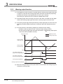
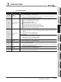
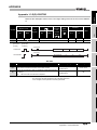
3.2.4
Rate control function
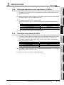
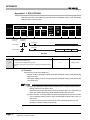
(1) The increase and decrease in analog output values per 6ms *1 can be limited, which
can prevent rapid change of the values.
*1 6ms is the D/A conversion cycle per channel.
(2) To use this function, the following settings are required for each setting.
• Enable the rate control function: rate control enable/disable setting (Un\G46)
• Set the increase/decrease of analog output value per 6ms: CH
decrease digital limit value (Un\G70 to Un\G81)
increase/
(3) Although values on a per-6ms basis are set in CH increase/decrease digital limit
value (Un\G70 to Un\G81), the actual cycle in which the Q66DA-G updates analog
values is (6ms x number of conversion-enabled channels).
Therefore, the maximum increase/decrease in analog output values under the rate
control is a D/A converted value of (Increase/decrease digital limit value x No. of conversion-enabled channels).
[Example Control of channel 3 when No. of conversion-enabled channels is 1 to 3]
• Output range: -10 to 10V
• Increase digital limit value: 100
• Decrease digital limit value: 100
Digital input value
Analog output value
Digital input value
Voltage of analog
output value (mV)
937.5
1500
0
Increase/derease
digital limit value
(100)
0
0.0
18
36
6ms
54
60
78
96
114
time(ms)
132
150 168
186
204
Update cycles of
analog output value (18ms)
When the digital input value changes, the analog output value increases or decreases
in update cycles as follows:
1st time: D/A converted value of the upper/lower digital limit value
2nd time or later: D/A converted value of (Increase/decrease digital limit value x No.
of conversion-enabled channels)
3 - 16
3.2 Function List
3.2.4 Rate control function
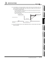
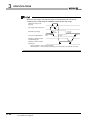
SPECIFICATIONS
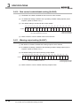
Rate control valid
Analog value converted
from digital input value
Analog output value
3
RUN
Programmable controller
CPU status
SPECIFICATIONS
Offse value
RUN
STOP(error)
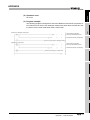
(5) When the scaling function is used, digital input values converted within the scaling
range are limited.
4
SETUP AND PROCEDURES BEFORE
OPERATION
Analog value converted
from digital input value
2
SYSTEM CONFIGURATION
(4) If the operation of the programmable controller CPU varies at the setting of D/A conversion enable, D/A output enable and analog output CLEAR, the rate control functions operate as indicated below.
• If the programmable controller CPU has switched from RUN to STOP (error):
Rate control does not function.
• If the programmable controller CPU has switched from STOP (error) to RUN:
Rate control functions.
OVERVIEW
1
UTILITY PACKAGE
(GX CONFIGURATOR-DA)
5
PROGRAMMING
6
ONLINE MODULE
CHANGE
7
8
TROUBLESHOOTING
3
3.2 Function List
3.2.4 Rate control function
3 - 17
3
SPECIFICATIONS
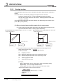
3.2.5
Scaling function
The digital input value range can be changed to any given range between -32000 and
32000.
To use this function, the following settings are required for each channel.
• Enable the scaling function: Scaling enable/disable setting (Un\G53)
• Set the scaling upper and lower limit values: Scaling upper/lower limit value
(Un\G54 to Un\G65)
The CH scaling upper/lower limit value settings vary depending on the output range.
(Refer to (1) and (2) below.)
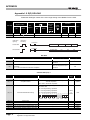
(1) When using the factory default setting for the output range
(a) As the scaling upper and lower limit values, set digital values equivalent to the
upper and lower limit values of analog output respectively.
[Example] When the output range is “0 to 5V” or “1 to 5V”
[Example] When the output range is “-10 to 10V”
Analog output value (V)
Analog output value (V)
10
5
0
1
Digital input value
0
Scaling lower
limit value
Digital input value
-10
Scaling upper
limit value
Scaling lower
limit value
Scaling upper
limit value
(b) The D/A conversion uses values calculated from the following formula.
DMax-DMin
Digital values actually used
=
for D/A conversion
SH-SL
DX
(DX-SL)+DMin
: Digital input value
DMax : Maximum digital input value of the output range used
DMin : Minimum digital input value of the output range used
SH
: Scaling upper limit value
SL
: Scaling lower limit value
[Example]
When a digital input value of 7000 is input under the following setting:
Output range: -10 to 10V, High resolution mode,
Scaling upper limit value: 14000, Scaling lower limit value: 2000
Digital values actually used for D/A conversion
16000-(-16000)
14000-2000
= -2666.66
= -2666
=
(7000-2000) + (-16000)
Fractional part is rounded down.
3 - 18
3.2 Function List
3.2.5 Scaling function
SPECIFICATIONS
1
2
SYSTEM CONFIGURATION
(a) Set a digital value, which is equivalent to the analog gain value to be output, as
the scaling upper limit value. Also, set a digital value, which is equivalent to the
analog offset value to be output, as the scaling lower limit value.
OVERVIEW
(2) When using the user range setting for the output range
[Example] User range setting 2, Offset value: 1V, Gain value: 8V
Analog output value (V)
8
3
SPECIFICATIONS
1
0
Digital input value
-6
Scaling upper
limit value
4
SETUP AND PROCEDURES BEFORE
OPERATION
Scaling lower
limit value
(b) The D/A conversion uses values calculated from the following formula.
Digital values actually
=
used for D/A conversion
DX
DMax
SH-SL
(DX-SL)
: Digital input value
5
UTILITY PACKAGE
(GX CONFIGURATOR-DA)
DMax: Maximum digital input value of the output range used
SH : Scaling upper limit value
: Scaling lower limit value
SL
[Example]
When a digital input value of 4000 is input under the following setting:
Output range: User range setting 2, High resolution mode,
Scaling upper limit value: 13000, Scaling lower limit value: 2000
PROGRAMMING
6
Digital values actually used for D/A conversion
12000
13000-2000
= 2181.81
= 2181
(4000-2000)
7
Fractional part is rounded down.
ONLINE MODULE
CHANGE
=
8
TROUBLESHOOTING
3
3.2 Function List
3.2.5 Scaling function
3 - 19
3
SPECIFICATIONS
(1) Even if the digital value input range is enlarged, the resolution will not be more
than the one applied when the scaling function is not used. As the digital
value input range is narrowed, the resolution is lowered.
(2) When a digital value input range not including zero (0), such as “1000 to
6000”, is specified, turn ON the output enable/disable flag after setting values
within the input range in the CH digital values (Un\G1 to Un\G6).
If the output enable/disable flag is turned ON with the default value (0) set in
the CH digital value, an error will occur and an error code will be stored in
the Error code (Un\G19).
(3) The check of the settable range is performed for “digital values actually used
for D/A conversion”.
(4) Depending on whether to use the scaling function or not, the analog output
value varies on the boundary between the inside and outside of the digital
input value setting range.
[Example 1]
Output range: 4 to 20mA, Normal resolution mode, and not using the scaling
function
By the conditions of the output range and resolution mode, the available
digital input value setting range is –96 to 4095.
When a digital value is the upper limit of the settable range, 4095 or higher, an
analog value equivalent to 4095 is output, which means the same analog
value is output for the digital values within and outside the setting range.
[Example 2]
Output range: 4 to 20mA, Normal resolution mode (same as Example 1), and
using the scaling function with:
Scaling upper limit value: 3000, Scaling lower limit value: 1000
When a digital value is the upper limit of the settable range, 3047 (4094 after
calculation), an analog value equivalent to 4094 is output.
On the other hand, if it is out of the settable range, which is 3048 or higher
(calculated value is 4096 or higher), an analog value equivalent to 4095 is
output.
As a result, the analog output value converted from the upper limit digital
value of the settable range is different from the one converted from the value
outside the settable range by 1 digit.
3 - 20
3.2 Function List
3.2.5 Scaling function
3
SPECIFICATIONS
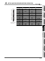
1
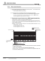
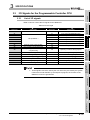
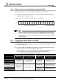
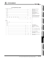
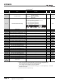
List of I/O signals
Q66DA-G
CPU module
Signal direction
CPU module
Q66DA-G
Device No
Signal name
Device No.
Signal name
X0
Module READY
Y0
Use prohibited *1
CH1 Output enable/disable flag
CH2 Output enable/disable flag
CH3 Output enable/disable flag
CH4 Output enable/disable flag
CH5 Output enable/disable flag
CH6 Output enable/disable flag
XD
XE
XF
completed flag
Offset/gain setting mode flag
Channel change completed flag
Set value change completed flag
Use prohibited *1
Warning output signal
Error flag
Use prohibited *1
Y9
Operating condition setting request
YA
YB
YC
User range writing request
Channel change request
Set value change request
YD
Use prohibited *1
Warning output clear request
Error clear request
YE
YF
*1 These signals cannot be used by the user since they are used by the system.
If these are turned ON/OFF by the sequence program, the function of the
Q66DA-G cannot be guaranteed.
4
5
6
PROGRAMMING
XA
XB
XC
External power supply READY
High resolution mode status flag
Operating condition setting
3
7
ONLINE MODULE
CHANGE
X9
Use prohibited
*1
Y1
Y2
Y3
Y4
Y5
Y6
Y7
Y8
8
TROUBLESHOOTING
X1
X2
X3
X4
X5
X6
X7
X8
SPECIFICATIONS
Table3.5 List of I/O signal
Signal direction
SYSTEM CONFIGURATION
2
Table 3.5 shows a list of the I/O signals for the Q66DA-G.
SETUP AND PROCEDURES BEFORE
OPERATION
3.3.1
OVERVIEW
I/O Signals for the Programmable Controller CPU
UTILITY PACKAGE
(GX CONFIGURATOR-DA)
3.3
3.3 I/O Signals for the Programmable Controller CPU
3.3.1 List of I/O signals
3 - 21
3
SPECIFICATIONS
3.3.2
Details of I/O signals
I/O signals for the Q66DA-G are explained in detail below.
(1) Input signals
Device No.
Signal name
Description
(1)
When the programmable controller CPU is powered on or reset, this signal turns ON when the
initial processings in the Q66DA-G are all completed.
X0
Module READY
(2)
When the Module READY (X0) signal is OFF, D/A conversion processing is not performed.
Module READY (X0) turns OFF in the following situations:
During offset/gain setting mode
When the Q66DA-G has a watchdog timer error
(1)
This signal turns on 100ms after turning on the external power supply.
(2)
In normal mode, when Module READY (X0) is OFF, this signal does not turn ON even if 100ms
have elapsed after turning on the external power supply.
In this case, as soon as Module READY (X0) turns ON, this signal (X7) turns ON.
(3)
In Offset/gain setting mode, when Offset/gain setting mode flag (XA) is OFF, this signal does
not turn on even if 100ms have elapsed after turning ON the external power supply.
In this case, as soon as Offset/gain setting mode flag (XA) turns on, this signal (X7) turns on.
(4)
D/A conversion is performed after the external power supply READY (X7) turns ON.
(5)
When the external power is not supplied or has been supplied for less than 100ms, X7 is OFF
and no D/A conversion is performed.
At this time, the analog output value is “0mA/0V” regardless of other settings, and no invalid
digital value error detection or no warning output is performed.
(6)
X7 might not turn ON when the external power supply does not meet the requirements shown
in the performance specifications (Refer to Table 3.1.).
(7)
The following time chart shows that the external power supply is turned ON after power-on of a
programmable controller CPU.
X7
ON
Power supply of a
programmable
controller CPU
External power supply READY
ON
In normal mode :(X0)
In offset/gain
setting mode :(XA)
ON
OFF
External power supply
100ms
ON
External power supply
READY(X7)
OFF
D/A conversion
is not performed
(8)
When performing D/A output, X0 and X7 must be ON as shown below.
Digital value
write command X0
X8
3 - 22
High resolution
mode status flag
(1)
D/A conversion
is performed
X7
This turns ON when in high resolution mode.
3.3 I/O Signals for the Programmable Controller CPU
3.3.2 Details of I/O signals
MOVP
K4000
U0\
G1
3
SPECIFICATIONS
1
This is used as an interlock condition for turning ON/OFF the operating condition setting
request (Y9) when any of the following settings is changed.
D/A conversion enable/disable setting (Un\G0)
Rate control enable/disable setting (Un\G46)
2
Warning output setting (Un\G47)
Scaling enable/disable setting (Un\G53)
Scaling upper/lower limit value (Un\G54 to Un\G65)
Increase/decrease digital limit value (Un\G70 to Un\G81)
Warning output upper/lower limit value (Un\G86 to Un\G97)
When operating condition setting request (Y9) is ON
Operating condition
X9
Under the following conditions, the operating condition setting completed flag (X9) turns OFF.
3
Performed by the Q66DA-G
Performed by the sequence program
setting completed
SPECIFICATIONS
flag
Module READY(X0)
Operating condition
setting completed flag(X9)
4
Operating codition
setting request(Y9)
[In offset/gain setting mode]
(1)
This is used as an interlock condition for turning ON/OFF the user range write request (YA)
when registering the value after adjustment of the offset/gain settings have been completed.
(2)
Refer to Section 4.6 regarding the offset/gain settings.
Performed by the Q66DA-G
Performed by the sequence program
Module READY(X0)
OFF
Offset/gain setting mode flag (XA)
SETUP AND PROCEDURES BEFORE
OPERATION
(2)
OVERVIEW
Description
(1)
SYSTEM CONFIGURATION
Signal name
5
UTILITY PACKAGE
(GX CONFIGURATOR-DA)
Device No.
6
[In normal mode]
(1)
This is used as an interlock condition to turn ON/OFF the User range write request (YA) when
(2)
Refer to Chapter 7 regarding the user range restoration.
the user range is restored.
Performed by the Q66DA-G
Performed by the sequence program
7
Module READY(X0) ON
ONLINE MODULE
CHANGE
mode flag
PROGRAMMING
Offset/gain setting
Offset/gain setting mode flag (XA)
User range write request (YA)
8
TROUBLESHOOTING
XA
User range write request (YA)
3.3 I/O Signals for the Programmable Controller CPU
3.3.2 Details of I/O signals
3 - 23
3
SPECIFICATIONS
Device No.
Signal name
Description
(1)
This is used as an interlock condition for turning ON/OFF the channel change request (YB)
when specifying the user range and channel to perform offset/gain settings.
(2)
Refer to Section 4.6 regarding the offset/gain settings.
Performed by the Q66DA-G
Performed by the sequence program
XB
Channel change
completed flag
Offset/gain setting mode, Offset/gain
specificaions (Un\G22, Un\G23)
Offset/gain range setting (Un\G25)
Channel change completed flag
(XB)
Channel change request (YB)
(1)
This is used as an interlock condition for turning ON/OFF the set value change request (YC)
when adjusting the offset/gain settings.
(2)
XC
Refer to Section 4.6 regarding the offset and gain settings.
Performed by the Q66DA-G
Performed by the sequence program
Set value change
completed flag
Set value change completed (XC)
Set value change request (YC)
(1)
This turns ON if the digital input value on any of the channels enabled for D/A conversion rises
to or above the warning output upper limit value or falls below the warning output lower limit
value.
(2)
Turning ON the warning output clear request (YE) or operating condition setting request (Y9)
turns OFF the warning output signal (XE).
XE
Performed by the Q66DA-G
Performed by the sequence program
Warning output signal
Warning output signal
(XE)
Warning output clear
request (YE)
(1)
(2)
The error flag (XF) turns ON when a write error occurs.
To turn the error flag (XF) OFF, remove the cause of the error and turn ON the error clear
request (YF).
The error code (Un\G19) changes to 0 and the ERR. LED turns off.
Performed by the Q66DA-G
Performed by the sequence program
XF
Error flag
Error code (Un\G19)
Error flag (XF)
Error clear request (YF)
3 - 24
3.3 I/O Signals for the Programmable Controller CPU
3.3.2 Details of I/O signals
Error occur
3
SPECIFICATIONS
1
CH
ON: D/A converted value OFF: Offset value
output enable/
disable flag
(2) The D/A conversion speed is 6ms X the number conversion-enabled channels regardless of
whether the output enable/disable flag is ON or OFF.
(1)
Turn ON this signal when changing any of the following settings and making the setting valid.
D/A conversion enable/disable setting (Un\G0)
Rate control enable/disable setting (Un\G46)
Y9
Warning output setting (Un\G47)
Operating condition
Scaling enable/disable setting (Un\G53)
setting request
3
Scaling upper/lower limit value (Un\G54 to Un\G65)
Increase/decrease digital limit value (Un\G70 to Un\G81)
Warning output upper/lower limit value (Un\G86 to Un\G97)
(2)
Refer to the X9 column for the ON/OFF timing.
[In offset/gain setting mode]
(1)
Turn ON this signal when the values for the adjusted offset/gain settings are registered in the
(2)
Refer to the XA column for ON/OFF timing.
Q66DA-G.
YA
User range write
request
4
Refer to Section 4.6 for offset/gain settings.
[In normal mode]
(1)
Turn ON this signal when restoring the user range.
(2)
Refer to the XA column for the ON/OFF timing.
Channel change
(1)
Turn ON this signal when specifying the user range and channel to perform offset/gain settings.
request
(2)
Refer to the XB column for the ON/OFF timing.
(1)
Turn ON/OFF this signal when increasing or decreasing the analog output value during adjust-
Refer to Chapter 7 for the user range restoration.
YB
YC
Set value change
request
ment of the offset/gain settings.
(2)
The analog output is incremented or decremented depending on the value set to the offset/gain
adjustment value specification (Un\G24).
request
Refer to the XE column for the ON/OFF timing.
(1)
Turn ON this signal when clearing a write error.
(2)
Refer to the XF column for ON/OFF timing.
6
PROGRAMMING
Error clear request
(2)
7
ONLINE MODULE
CHANGE
YF
Turn ON this signal when clearing the warning output.
5
8
TROUBLESHOOTING
YE
Warning output clear (1)
2
SPECIFICATIONS
Y1 to Y6
SYSTEM CONFIGURATION
Description
(1) Specify whether to output the D/A converted value or output the offset value for each channel.
SETUP AND PROCEDURES BEFORE
OPERATION
Signal name
UTILITY PACKAGE
(GX CONFIGURATOR-DA)
Device No.
OVERVIEW
(2) Output signals
3.3 I/O Signals for the Programmable Controller CPU
3.3.2 Details of I/O signals
3 - 25
3
SPECIFICATIONS
When the user range write request (YA) is turned ON with D/A conversion
enabled in the normal mode, the Q66DA-G restores the user range.
Offset/gain setting mode
flag (XA)
User range write request (YA)
During
restoration
Restoration processig
Conversion enable/disable
During conversion
enable
Restoration
completed
During conversion
disable
Operating condition change
completed flag (X9)
Operating condition change
request(Y9)
During restoration : D/A conversion disable
After restoration : D/A conversion processing can be executed in the restored user range
3 - 26
3.3 I/O Signals for the Programmable Controller CPU
3.3.2 Details of I/O signals
3
SPECIFICATIONS
1
Buffer memory assignment
16H
22
17H
23
18H
19H
1AH
to
2DH
2EH
2FH
30H
31H
To
34H
24
25
26
to
45
46
47
48
49
to
52
Read/write *2
003FH
0
0
0
0
0
0
R/W
R/W
R/W
R/W
R/W
R/W
R/W
System area
-
-
CH1 Set value check code
CH2 Set value check code
CH3 Set value check code
CH4 Set value check code
CH5 Set value check code
CH6 Set value check code
0
0
0
0
0
0
R
R
R
R
R
R
System area
-
-
Error code
Setting range (CH1 to CH4)
Setting range (CH5, CH6)
Offset/gain setting mode
0
0
0
R
R
R
0
R/W
D/A conversion enable/disable setting
CH1 Digital value
CH2 Digital value
CH3 Digital value
CH4 Digital value
CH5 Digital value
CH6 Digital value
Offset specification
Offset/gain setting mode
Gain specification
Offset/gain adjustment value specification
Offset/gain range setting
0
R/W
0
0
R/W
R/W
System area
-
-
003FH
003FH
0
R/W
R/W
R
-
-
Rate control enable/disable setting
Warning output setting
Warning output flag
System area
*1 This is the initial value set after the power is turned on or the programmable controller CPU is reset.
*2 Indicates whether reading from and writing to a sequence program are enabled.
R : Reading enabled W : Writing enabled
3.4 Buffer Memory
3.4.1 Buffer memory assignment
3 - 27
SPECIFICATIONS
Default *1
4
SETUP AND PROCEDURES BEFORE
OPERATION
Description
5
UTILITY PACKAGE
(GX CONFIGURATOR-DA)
Table3.6 Buffer memory assignment (1/3)
Address
Hexadecimal
Decimal
0H
0
1H
1
2H
2
3H
3
4H
4
5H
5
6H
6
7H
7
to
to
AH
10
BH
11
CH
12
DH
13
EH
14
FH
15
10H
16
11H
17
12H
18
13H
19
14H
20
15H
21
3
6
PROGRAMMING
Do not write data from system area or sequence program to the buffer memory
area where writing is disabled.
Doing so may cause malfunction.
SYSTEM CONFIGURATION
2
Table 3.6 indicates the buffer memory assignment of the Q66DA-G.
7
ONLINE MODULE
CHANGE
3.4.1
OVERVIEW
Buffer Memory
8
TROUBLESHOOTING
3.4
3
SPECIFICATIONS
Table 3.6 Buffer memory assignment (2/3)
Address
Description
Default *1
Read/write *2
Hexadecimal
Decimal
35H
53
Scaling enable/disable setting
003FH
R/W
36H
54
CH1 Scaling lower limit value
0
R/W
37H
55
CH1 Scaling upper limit value
0
R/W
38H
56
CH2 Scaling lower limit value
0
R/W
39H
57
CH2 Scaling upper limit value
0
R/W
3AH
58
CH3 Scaling lower limit value
0
R/W
3BH
59
CH3 Scaling upper limit value
0
R/W
3CH
60
CH4 Scaling lower limit value
0
R/W
3DH
61
CH4 Scaling upper limit value
0
R/W
3EH
62
CH5 Scaling lower limit value
0
R/W
3FH
63
CH5 Scaling upper limit value
0
R/W
40H
64
CH6 Scaling lower limit value
0
R/W
41H
65
CH6 Scaling upper limit value
0
R/W
42H
66
System area
-
-
to
to
45H
69
46H
70
CH1 Increase digital limit value
64000
R/W
47H
71
CH1 Decrease digital limit value
64000
R/W
48H
72
CH2 Increase digital limit value
64000
R/W
49H
73
CH2 Decrease digital limit value
64000
R/W
4AH
74
CH3 Increase digital limit value
64000
R/W
4BH
75
CH3 Decrease digital limit value
64000
R/W
4CH
76
CH4 Increase digital limit value
64000
R/W
4DH
77
CH4 Decrease digital limit value
64000
R/W
4EH
78
CH5 Increase digital limit value
64000
R/W
4FH
79
CH5 Decrease digital limit value
64000
R/W
50H
80
CH6 Increase digital limit value
64000
R/W
51H
81
CH6 Decrease digital limit value
64000
R/W
52H
82
System area
-
R/W
to
to
55H
85
56H
86
CH1 Warning output upper limit value
0
57H
87
CH1 Warning output lower limit value
0
R/W
58H
88
CH2 Warning output upper limit value
0
R/W
59H
89
CH2 Warning output lower limit value
0
R/W
5AH
90
CH3 Warning output upper limit value
0
R/W
5BH
91
CH3 Warning output lower limit value
0
R/W
5CH
92
CH4 Warning output upper limit value
0
R/W
5DH
93
CH4 Warning output lower limit value
0
R/W
5EH
94
CH5 Warning output upper limit value
0
R/W
5FH
95
CH5 Warning output lower limit value
0
R/W
60H
96
CH6 Warning output upper limit value
0
R/W
61H
97
CH6 Warning output lower limit value
0
R/W
*1 This is the initial value set after the power is turned on or the programmable controller CPU is reset.
*2 Indicates whether reading from and writing to a sequence program are enabled.
R : Reading enabled W : Writing enabled
3 - 28
3.4 Buffer Memory
3.4.1 Buffer memory assignment
3
SPECIFICATIONS
1
9EH
158
9FH
159
A0H
160
to
to
C7H
199
C8H
200
-
-
0
R/W
0
R/W
System area
-
-
Save data classification setting*3
0
R/W
System area
Mode switching setting
C9H
201
System area
-
-
CAH
202
CH1 Factory default setting offset value*3
0
R/W
CBH
203
CH1 Factory default setting gain value*3
CCH
204
CH2 Factory default setting offset value
CDH
205
CEH
206
0
R/W
0
R/W
CH2 Factory default setting gain value*3
0
R/W
CH3 Factory default setting offset value*3
0
R/W
*3
*3
CFH
207
D0H
208
CH4 Factory default setting offset value
D1H
209
D2H
210
0
R/W
0
R/W
CH4 Factory default setting gain value*3
0
R/W
CH5 Factory default setting offset value*3
0
R/W
CH3 Factory default setting gain value
*3
*3
D3H
211
D4H
212
CH6 Factory default setting offset value
D5H
213
D6H
0
R/W
0
R/W
CH6 Factory default setting gain value*3
0
R/W
214
CH1 User range settings offset value*3
0
R/W
D7H
215
CH1 User range settings gain value*3
D8H
216
CH2 User range settings offset value
D9H
217
DAH
218
CH5 Factory default setting gain value
*3
0
R/W
0
R/W
CH2 User range settings gain value *3
0
R/W
CH3 User range settings offset value*3
0
R/W
*3
*3
DBH
219
DCH
220
CH4 User range settings offset value
DDH
221
DEH
222
0
R/W
0
R/W
CH4 User range settings gain value *3
0
R/W
CH5 User range settings offset value*3
0
R/W
CH3 User range settings gain value
*3
*3
DFH
223
E0H
224
CH6 User range settings offset value
E1H
225
CH6 User range settings gain value *3
CH5 User range settings gain value
*3
0
R/W
0
R/W
0
R/W
*1 This is the initial value set after the power is turned on or the programmable controller CPU is reset.
*2 Indicates whether reading from and writing to a sequence program are enabled.
R : Reading enabled W : Writing enabled
*3 Areas used to restore the user range settings offset/gain values when online module change is
made.
Refer to Chapter 7 for details of online module change.
2
SYSTEM CONFIGURATION
157
3
SPECIFICATIONS
to
9DH
Read/write *2
4
SETUP AND PROCEDURES BEFORE
OPERATION
98
to
Default *1
5
UTILITY PACKAGE
(GX CONFIGURATOR-DA)
62H
Description
6
PROGRAMMING
Decimal
7
ONLINE MODULE
CHANGE
Address
Hexadecimal
OVERVIEW
Table 3.6 Buffer memory assignment (3/3)
TROUBLESHOOTING
8
3.4 Buffer Memory
3.4.1 Buffer memory assignment
3 - 29
3
SPECIFICATIONS
3.4.2
D/A conversion enable/disable setting (Un\G0)
(1) Set whether D/A conversion is enabled or disabled for each channel.
(2) To validate the settings, ON/OFF of the Operating condition setting request (Y9) is
required. (Refer to Section 3.3.2.)
(3) By default, all channels are set to D/A conversion disabled.
b15 b14 b13 b12
Un\G0
0
0
0
0
b11
b10
0
0
b9
b8
0
b7
0
0
b6
0
b5
b4
b3
b2
b1
b0
CH
CH
CH
CH
CH
CH
6
5
4
3
2
1
1: D/A connversion disabled
0: D/A conversion enabled
b6 to b15 information is fixed at 0.
Design the system so that the D/A conversion enable/disable setting (Un\G0)
changes to "Enable" after the external power (Refer to Section 4.3) is supplied.
Analog output may not be performed properly if the external power is not at the
specified voltage.
3.4.3
CH
digital values (Un\G1 to Un\G6)
(1) This area is used to write digital values from the programmable controller CPU as 16bit signed binary code.
(2) If a value outside the settable range is written, the upper or lower limit value of the
range is used for D/A conversion. (Refer to Table 3.7.)
Also, if this happens, a check code and an error code will be stored in the Set value
check code (Un\G11 to Un\G16) and Error code (Un\G19) respectively.
Table3.7 Output range settings and settable range
Normal resolution mode
Output range setting
Settable range
(practical range)
0: 4 to 20 mA
-96 to 4095
1: 0 to 20 mA
(Practical range:
2: 1 to 5 V
0 to 4000)
3: 0 to 5 V
Digital value that is set when
a value outside the settable
range is written
4096 or larger: 4095
-97 or smaller: -96
High resolution mode
Settable range
(practical range)
-288 to 12287
(Practical range:
0 to 12000)
-16384 to 16383
4: –10 to 10 V
-4096 to 4095
D: User range setting3
E: User range setting2
(Practical range:
-4000 to 4000)
(Practical range:
4096 or larger: 4095
-16000 to 16000)
-4097 or smaller: -4096
-12288 to 12287
F: User range setting1
3 - 30
3.4 Buffer Memory
3.4.2 D/A conversion enable/disable setting (Un\G0)
(Practical range:
-12000 to 12000)
Digital value that is set when
a value outside the settable
range is written
12288 or larger: 12287
-289 or smaller: -288
16384 or larger: 16383
-16385 or smaller: -16384
12288 or larger: 12287
-12289 or smaller: -12288
SPECIFICATIONS
1
Table3.8 Check code list
Check code
Description
000FH
A digital value exceeding the settable range is written.
00F0H
A digital value that falls short of the settable range is written.
A digital value that either falls short or exceeds the settable range was written.
00FFH
For example, the 00FFH check code is stored if a digital value exceeding the
valid range is written, and then, without the check code being reset, a digital
value that falls short of the settable range is written.
(3) Once a check code is stored, it will not be reset even if the digital value is within the
settable range.
(4) To reset the CH set value check code, set the error clear request (YF) to ON after
rewriting the digital value so that it is within the settable range.
(5) When the scaling function is used, digital values converted from the digital values set
in CH Digital values (Un\G1 to Un\G6) are checked. (Refer to Section 3.2.5.)
Error codes (Un\G19)
3
4
UTILITY PACKAGE
(GX CONFIGURATOR-DA)
5
(1) This area stores the error codes detected by the Q66DA-G.
(2) Refer to Section 8.1 for more details of the error codes.
PROGRAMMING
6
7
ONLINE MODULE
CHANGE
3.4.5
2
SYSTEM CONFIGURATION
(2) When a digital value outside the settable range (Refer to Section 3.4.3 and Table 3.7)
is written, one of the check codes listed in Table 3.8 is stored.
SPECIFICATIONS
(1) Digital values set in CH Digital value (Un\G1 to Un\G6) are checked and if any of
them is outside the settable range, the check result is stored in this area.
OVERVIEW
CH[ ]set value check codes (Un\G11 to Un\G16)
SETUP AND PROCEDURES BEFORE
OPERATION
3.4.4
8
TROUBLESHOOTING
3
3.4 Buffer Memory
3.4.4 CH[ ]set value check codes (Un\G11 to Un\G16)
3 - 31
3
SPECIFICATIONS
3.4.6
Setting range (Un\G20, Un\G21)
(1) This area is used to confirm the setting range of the Q66DA-G.
b15
b12
Un\G20
(setting range CH1 to CH4)
Un\G21
(setting range CH5, CH6)
b11
b8
b7
b4
b3
b0
CH4
CH3
CH2
CH1
0H
0H
CH6
CH5
b8 to b15 information is fixed at 0.
Output range
4 to 20 (mA)
0 to 20 (mA)
1 to 5 (V)
0 to 5 (V)
–10 to 10 (V)
User range setting 3
User range setting 2
User range setting 1
3.4.7
Storing value
0H
1H
2H
3H
4H
DH
EH
FH
Offset/gain setting mode and offset/gain specification (Un\G22,
Un\G23)
(1) Specifies the channel to be adjusted for the offset/gain settings.
(2) The channel change request (YB) must be turned ON/OFF to validate the offset/gain
setting. (Refer to Section 3.3.2.)
(3) Specification can be made for 1 channel only.
If more than one channel is set at the same time, an error occurs and an error code is
stored in the Error code (Un\G19).
(4) Refer to Section 4.6 for the details of the offset/gain settings.
b15 b14 b13 b12
Un\G22
(Offset specification)
0
Un\G23
(gain specification)
0
0
0
0
0
0
0
b11
0
0
b10
0
0
b9
0
0
b8
0
0
b6 to b15 information is fixed at 0.
3 - 32
3.4 Buffer Memory
3.4.6 Setting range (Un\G20, Un\G21)
b7
0
0
b6
0
0
b5
b4
b3
b2
b1
b0
CH
CH
CH
CH
CH
CH
6
5
4
3
2
1
CH
CH
CH
CH
CH
CH
6
5
4
3
2
1
1: Channel to be set
0: Invalid
SPECIFICATIONS
1
(2) Turning the set value change request (YC) from OFF to ON increments or decrements
the analog output value by the adjustment value.
(3) The settable input range is from -3000 to 3000.
When the set value is 1000, the analog output values can be adjusted by following
value.
Adjustment when set value is 1000
Approx. 0.86mA
User range setting2
Approx. 0.38V
User range setting3
Approx. 0.19V
(4) Refer to Section 4.6 for details of offset/gain setting.
Offset/gain range setting (Un\G25)
(1) This area is used to change the output range in the offset/gain setting mode. Turning
ON the channel change request (YB) changes the output range into the set one.
If any value outside the setting range is set, an error occurs and the corresponding
error code (Un\G19) is stored.
Output range
Set value
User range setting 1
000FH
User range setting 2
000EH
User range setting 3
000DH
SETUP AND PROCEDURES BEFORE
OPERATION
4
5
(2) The channel change request (YB) must be turned ON/OFF to validate the offset/gain
range setting. (Refer to Section 3.3.2.)
(3) Refer to Section 4.6 for details of offset/gain setting.
PROGRAMMING
6
7
ONLINE MODULE
CHANGE
3.4.9
3
SPECIFICATIONS
Output range
User range setting1
2
SYSTEM CONFIGURATION
(1) This area is used to set the amount of adjustment for analog output values in the offset/gain setting mode.
OVERVIEW
Offset/gain adjustment value specification (Un\G24)
UTILITY PACKAGE
(GX CONFIGURATOR-DA)
3.4.8
8
TROUBLESHOOTING
3
3.4 Buffer Memory
3.4.8 Offset/gain adjustment value specification (Un\G24)
3 - 33
3
SPECIFICATIONS
3.4.10 Rate control enable/disable setting (Un\G46)
(1) Set whether to enable or disable the rate control on each channel.
(2) To validate the settings, ON/OFF of the operating condition setting request (Y9) is
required. (Refer to Section 3.3.2.)
(3) The default setting is all-channel rate control disable.
b15 b14 b13 b12
Un\G46
0
0
0
0
b11
0
b10
0
b9
0
b8
0
b7
0
b6
0
b5
b4
b3
b2
b1
b0
CH
CH
CH
CH
CH
CH
6
5
4
3
2
1
1: Rate control disable
0: Rate control enable
b6 to b15 information is fixed at 0
(4) Refer to Section 3.2.4 for details of rate control function.
3.4.11 Warning output setting (Un\G47)
(1) Set whether to enable or disable the warning output on each channel.
(2) To validate the settings, ON/OFF of the operating condition setting request (Y9) is
required. (Refer to Section 3.3.2.)
(3) The default setting is all-channel warning output disable.
b15 b14 b13 b12
Un\G47
0
0
0
0
b11
0
b10
0
b9
0
b8
0
b7
0
b6
0
b5
b4
b3
b2
b1
b0
CH
CH
CH
CH
CH
CH
6
5
4
3
2
1
b6 to b15 information is fixed at 0
(4) Refer to Section 3.2.3 for details of warning output function.
3 - 34
3.4 Buffer Memory
3.4.10 Rate control enable/disable setting (Un\G46)
1: Warning output disable
0: Warning output enable
SPECIFICATIONS
1
(4) Turning ON the operating condition setting request (Y9) or warning output clear
request (YE) clears the warning output flag.
b10
b9
b8
b7
b6
b5
b4
b3
b2
b1
b0
Un\G48
0
0
0
0
lower upper lower upper lower upper lower upper lower upper lower upper
limit limit limit limit limit limit limit limit limit limit limit limit
value value value value value value value value value value value value
1: Warning output
0: Normal
b12 to b15 information is fixed at 0
(5) Refer to Section 3.2.3 for details of warning output function.
3.4.13 Scaling enable/disable setting (Un\G53)
5
(1) Set whether to enable or disable the scaling on each channel.
(2) To validate the settings, ON/OFF of the Operating condition setting request (Y9) is
required. (Refer to Section 3.3.2.)
(3) The default setting is all-channel scaling disable.
b15 b14 b13 b12
Un\G53
0
0
0
0
b11
0
b10
0
b9
0
b8
0
b7
0
b6
0
b5
b4
b3
b2
b1
b0
CH
CH
CH
CH
CH
CH
6
5
4
3
2
1
b6 to b15 information is fixed at 0
4
1: Scaling disable
0: Scaling enable
(4) Refer to Section 3.2.5 for details of warning output function.
UTILITY PACKAGE
(GX CONFIGURATOR-DA)
b11
CH6 CH6 CH5 CH5 CH4 CH4 CH3 CH3 CH2 CH2 CH1 CH1
3
6
PROGRAMMING
b15 b14 b13 b12
SYSTEM CONFIGURATION
(3) If the warning is detected on any of the channels enabled for conversion, the warning
output signal (XE) turns ON.
2
SPECIFICATIONS
(2) Whether the warning is the upper or lower limit value warning can be checked on each
channel.
SETUP AND PROCEDURES BEFORE
OPERATION
(1) When the digital input value falls outside the CH warning output upper limit value/
lower limit value (Un\G86 to Un\G97) range, the bit corresponding to each channel
turns to "1".
OVERVIEW
3.4.12 Warning output flag (Un\G48)
ONLINE MODULE
CHANGE
7
8
TROUBLESHOOTING
3
3.4 Buffer Memory
3.4.12 Warning output flag (Un\G48)
3 - 35
3
SPECIFICATIONS
3.4.14 Scaling upper/lower limit value (Un\G54 to Un\G65)
(1) When the scaling function is used, set a digital value input range. (Refer to Section
3.2.5.)
(2) The setting range is -32000 to 32000.
Set them so that the scaling upper limit value is greater than the scaling lower limit
value.
If any value outside the setting range is set, an error occurs and the corresponding
error code (Un\G19) is stored.
(3) To validate the settings, ON/OFF of the operating condition setting request (Y9) is
required. (Refer to Section 3.3.2.)
3.4.15 CH
increase/decrease digital limit values (Un\G70 to Un\G81)
(1) For rate control, set the range where the digital value can be incremented and decremented in a conversion cycle per channel (6ms). (Refer to Section 3.2.4.)
(2) The setting range is 0 to 64000 (0 to FA00H).
If any value outside the setting range is set, an error occurs and the corresponding
error code is stored in error code (Un\G19).
(3) The operating condition setting request (Y9) must be turned ON/OFF to validate the
settings. (Refer to Section 3.3.2.)
When setting CH increase/decrease digital limit values (Un\G70 to Un\G81)
from the sequence program, values from 0 to 32767 can be set as decimal numbers without change. Note that this is not applicable to 32768 to 65535. These
values must be converted to hexadecimal numbers before setting.
3.4.16 CH warning output upper limit value/lower limit value (Un\G86
to Un\G97)
(1) Set the upper and lower limit values of the digital input value for providing the warning
output. (Refer to Section 3.2.3.)
(2) The setting range is -32000 to 32000.
Make setting so that the upper limit value is greater than the lower limit value.
If any value outside the setting range is set, an error occurs and the corresponding
error code (Un\G19) is stored.
(3) The operating condition setting request (Y9) must be turned ON/OFF to validate the
settings. (Refer to Section 3.3.2.)
3 - 36
3.4 Buffer Memory
3.4.14 Scaling upper/lower limit value (Un\G54 to Un\G65)
SPECIFICATIONS
1
Normal mode
Offset/gain setting mode
If the values written are other than the above, mode switching is not performed
and only the operating condition is changed.
3.4.18 Save data classification setting (Un\G200)
(1) Areas used to restore the user range settings offset/gain values when online module
change is made.
Refer to Chapter 7 for details of online module change.
(2) Specify the user range setting to be saved/restored when saving/restoring the offset/
gain values of any of the user range settings 1 to 3.
b15 b14 b13 b12
Un\G200
0
0
0
0
b11
b10
CH6
b12 to b15 information is fixed at 0
b9
b8
CH5
b7
b6
CH4
b5
b4
CH3
b3
CH2
b2
b1
b0
CH1
00: User range setting 1 specification
01: User range setting 2 specification
10: User range setting 3 specification
SYSTEM CONFIGURATION
Set values
Buffer memory address 158 Buffer memory address 159
0964H
4144H
4144H
0964H
3
SPECIFICATIONS
Mode to be switched to
4
SETUP AND PROCEDURES BEFORE
OPERATION
(3) When mode switching is performed, this area is cleared to zero and the operating
condition setting completed flag (X9) turns OFF.
After confirming that the operating condition setting completed flag (X9) has turned
OFF, turn OFF the operating condition setting request (Y9)
2
5
UTILITY PACKAGE
(GX CONFIGURATOR-DA)
(2) After setting the values, turning the operation condition setting request (Y9) from OFF
to ON enables mode switching.
6
PROGRAMMING
(1) Set the values of the mode to switch.
OVERVIEW
3.4.17 Mode switching setting (Un\G158, Un\G159)
7
ONLINE MODULE
CHANGE
Refer to Section 4.6 for the offset/gain value setting method.
8
TROUBLESHOOTING
3
3.4 Buffer Memory
3.4.17 Mode switching setting (Un\G158, Un\G159)
3 - 37
3
SPECIFICATIONS
3.4.19 Factory default setting and user range settings offset/gain values (Un\G202 to Un\G225)
(1) Areas used to restore the user range settings offset/gain values when online module
change is made.
Refer to Chapter 7 for details of online module change.
(2) When the offset/gain values of the user range setting are restored, the used data are
stored.
The data are stored (saved) when:
• Initial setting write is performed by the utility;
• The operating condition is set (Y9 turns from OFF to ON );
• The offset/gain values are written in the offset/gain setting mode (YA turns from
OFF to ON).
*: The data are not saved when the set values have been written to the mode switch setting
(Un\G158, Un\G159).
(3) When restoring the offset/gain values of the user range setting, set the data saved in
this area similarly into the corresponding area of the module where the data will be
restored.
(4) Buffer memory saving record procedure for online module change
1) Set the save data classification setting (Un\G200).
2) Turn the operating condition setting request (Y9) from OFF to ON.
3) Compare the offset/gain values of the factory default setting and user range
settings (Un\G202 to Un\G217) with the range reference table. Refer to Section 7.4 for the range reference table.
4) If the values are proper, record the offset/gain values of the save data classification setting, factory default setting and user range settings.
Refer to Section 4.6 for the offset/gain value setting method.
3 - 38
3.4 Buffer Memory
3.4.19 Factory default setting and user range settings offset/gain values (Un\G202 to Un\G225)
4
SETUP AND PROCEDURES BEFORE OPERATION
1
Handling Precautions
(3) Be careful not to let foreign materials such as swarf or wire chips enter the module.
They may cause a fire, mechanical failure or malfunction.
(4) The top surface of the module is covered with a protective film to prevent foreign
materials such as wire chips from entering the module during wiring.
Do not remove this film until the wiring is completed. Before operating the system, be
sure to remove the film to provide adequate heat radiation.
(5) Tighten the screws such as module fixing screws within the following ranges.
4
Tightening torque range
0.36 to 0.48 N m
Connector screw (M2.6 screw)
0.20 to 0.29 N m
FG Terminal screw (M3 screw)
0.42 to 0.58 N m
(6) To mount the module on the base unit, fully insert the module fixing latch into the fixing hole in the base unit, using the module fixing hole as a fulcrum.
Improper installation may result in a module malfunction or failure, or may cause the
module to fall off.
5
UTILITY PACKAGE
(GX CONFIGURATORDA)
Screw location
SETUP AND
PROCEDURES
BEFORE OPERATION
Loose screws may cause short circuits, failures or malfunctions.
Module fixing screw (M3 screw)
3
SPECIFICATIONS
(2) Do not remove the PCB of the module from its case. Doing so may cause the module
failure.
SYSTEM
CONFIGURATION
2
(1) Do not drop the module case or subject it to heavy impact.
PROGRAMMING
6
7
ONLINE MODULE
CHANGE
4.1
OVERVIEW
SETUP AND PROCEDURES BEFORE OPERATION
8
TROUBLESHOOTING
4
4.1 Handling Precautions
4-1
4
SETUP AND PROCEDURES BEFORE OPERATION
(7) Fix the Q66DA-G with module fixing bracket after the Q66DA-G is mounted to the
base unit.
Make sure that the hook at the tip of the module fixing bracket is hooked on the
3rd slit viewed from the front of Q66DA-G.
Tighten the module fixing screw by the specified torque.
Module fixing bracket
3rd slit
Module fixing screw
Q66DA-G
4-2
4.1 Handling Precautions
4
SETUP AND PROCEDURES BEFORE OPERATION
1
OVERVIEW
Setup and Procedures before Operation
Start
2
SYSTEM
CONFIGURATION
Module mounting
Mounting the Q66DA-G in the specified slot
wiring
Wire external devices to the Q66DA-G
(see Section 4.3, 4.4)
SPECIFICATIONS
3
Intelligent functional module switch settings
Perform settings using GX Developer
(See setcion 4.5)
Use the factory default
setting output range
4
SETUP AND
PROCEDURES
BEFORE OPERATION
Use user range settings?
Use user range settings
Offset/gain setting
If user range settings are used, perform the
offset and gain settings (see Section 4.6)
UTILITY PACKAGE
(GX CONFIGURATORDA)
5
NO
Use the utility package?
YES
6
Initial setting and automatic refresh setting
PROGRAMMING
The program can be simplified if the utility
package is used for setting (see Chapter 5).
Programing and debugging
Create and check sequence program.
(see Chapter 6)
ONLINE MODULE
CHANGE
7
8
TROUBLESHOOTING
4.2
4.2 Setup and Procedures before Operation
4-3
4
SETUP AND PROCEDURES BEFORE OPERATION
4.3
Part Names
The name of each part in the Q66DA-G is listed below.
Module fixing screw
1)
Module fixing bracket
2)
3)
Q66DA-G
RUN
External device
connector
ALM
ERR.
D/A
Terminal
number
A1
Terminal
number
B1
B20
A20
Q66DA-G
(FG)
4)
Number
Name
Description
Displays the operating status of the Q66DA-G.
On
1)
RUN LED
: Normal operation
Flashing
: During offset/gain setting mode
Off
: 5V power switched off, watchdog timer error
occurred, or online module change enabled.
Displays the error status of the Q66DA-G.
On
2)
ERR. LED
Flashing
: Error (Refer to Section 8.1)
Error in switch settings
Switch No. 5 of the intelligent function module has
been set to a value other than zero "0".
Off
: Normal operation
Indicates the warning status of the Q66DA-G.
3)
4)
ALM LED
FG terminal L-Shaped
metal fitting
On
: During warning output occurrence (Refer to Section
Off
: Normal operation
3.2.3)
Metal fitting to wire for FG of the Q66DA-G
When two or more errors have occurred, the latest error found by the Q66DA-G is
displayed on the LED.
4-4
4.3 Part Names
SETUP AND PROCEDURES BEFORE OPERATION
CH1 I +
B2
-
A3
-
B3
-
A4
CH2 V +
B4
CH1 COM2
A5
CH2 I +
B5
-
A6
-
B6
-
A7
CH3 V +
B7
CH1 COM3
A8
CH3 I +
B8
-
A9
-
B9
-
A10
CH4 V +
B10
CH1 COM4
-
A11
CH4 I +
B11
A12
-
B12
-
A13
CH5 V +
B13
CH1 COM5
A14
CH5 I +
B14
-
A15
-
B15
-
A16
CH6 V +
B16
CH1 COM6
A17
CH6 I +
B17
-
A18
-
B18
-
A19
24VDC
B19
24VDC
A20
24GDC
B20
24GDC
2
SYSTEM
CONFIGURATION
CH1 COM1
A2
3
SPECIFICATIONS
Signal name
B1
SETUP AND
PROCEDURES
BEFORE OPERATION
4
5
UTILITY PACKAGE
(GX CONFIGURATORDA)
Seen from the front
of the module
Terminal number
CH1 V +
6
PROGRAMMING
B1
B2
B3
B4
B5
B6
B7
B8
B9
B10
B11
B12
B13
B14
B15
B16
B17
B18
B19
B20
Signal name
A1
7
ONLINE MODULE
CHANGE
A1
A2
A3
A4
A5
A6
A7
A8
A9
A10
A11
A12
A13
A14
A15
A16
A17
A18
A19
A20
Terminal number
OVERVIEW
1
8
TROUBLESHOOTING
4
4.3 Part Names
4-5
4
SETUP AND PROCEDURES BEFORE OPERATION
4.4
Wiring
The wiring precautions and examples of module connection are provided below.
4.4.1
Wiring precautions
In order to optimize the functions of the Q66DA-G and ensure system reliability, external
wiring that is protected from noise is required.
The following shows the precautions for external wiring.
(1) Use separate cables for the alternating-current control circuit and the external output
signals and external supply power of the Q66DA-G in order to avoid AC surges and
induction effects.
(2) Do not mount the cables close to or bundle them with the main circuit line, a high-voltage cable or a load cable from other than the programmable controller. This may
increase the effects of noise, surges and induction.
(3) Perform a one-point grounding for shielded lines and the shields of shielded cables.
(4) When the wiring of the module mounted right to the Q66DA-G is difficult, perform wiring after removing the Q66DA-G.
4-6
4.4 Wiring
4.4.1 Wiring precautions
SETUP AND PROCEDURES BEFORE OPERATION
1
(1) For voltage output
1
2
Motor driving
module etc.
1k
D/A
conversion
OVERVIEW
External wiring
2
SYSTEM
CONFIGURATION
V+
COM
GND
+15V
1M
24VDC
3
24V
SPECIFICATIONS
FG
A.G
-15V
*1 Use a twisted two-core shielded wire for the power wire.
*2 If there is noise or ripples in the external wiring, connect a 0.1 to 0.47 F25V capacitor between the
V+ terminal and COM terminal.
(2) For current output
1
2
Motor driving
module etc.
0
D/A
conversion
I+
COM
GND
+15V
600
24VDC
24G
PROGRAMMING
filter
5
6
24V
DC/DC
converter
4
SETUP AND
PROCEDURES
BEFORE OPERATION
filter
24G
UTILITY PACKAGE
(GX CONFIGURATORDA)
DC/DC
converter
FG
A.G
-15V
*1 Use a twisted two-core shielded wire for the power wire.
*2 If there is noise or ripples in the external wiring, connect a 0.1 to 0.47 F25V capacitor between the
I+ terminal and COM terminal.
Q66DA-G needs to be powered on 30 minutes prior to operation for compliance to
the specification (accuracy).
Similarly, power on 30 minutes prior to offset/gain setting or after online module
replacement.
4.4 Wiring
4.4.2 External wiring
4-7
7
ONLINE MODULE
CHANGE
4.4.2
8
TROUBLESHOOTING
4
4
SETUP AND PROCEDURES BEFORE OPERATION
4.5
Intelligent Function Module Switch Setting
The intelligent function module switch settings are performed using the I/O assignment
settings of GX Developer.
(1) Setting item
The intelligent function module switches consist of switches 1 to 5 and are set using
16 bit data. When the intelligent function module switches are not set, the default
value for switches 1 to 5 is 0.
Table4.1 Switch setting item for intelligent function module
Setting item
Output range
Switch 1
Analog output range
setting(CH1to CH4)
H
CH4 CH3 CH2 CH1
Output range setting value
4 to 20 mA
0H
0 to 20 mA
1H
1 to 5 V
2H
Output range setting
0 to 5 V
3H
(CH5, CH6)
-10 to 10 V
4H
User range setting3
DH
User range setting2
EH
User range setting1
FH
Switch 2
H
CH6 CH5
00H: Fixed
b15
Switch 3
b6 b5
b4
b3
b2
b1
b0
CH6 CH5 CH4 CH3 CH2 CH1
HOLD/CLEAR function setting
0: CLEAR
1: HOLD
0:Fixed
H
Switch 4
00H:Fixed
0H: Normal resolution mode
1 to FH(numeric value other than 0H) : Higih resolution mode
0H: Normal mode (D/A conversion processing)
1 to FH(numeric value other than 0H) : Offset/gain setting mode
Switch 5
0 : Fixed
* Setting any value within the setting range provides the same operation.
When the setting range is 1 to FH, set 1 for example.
4-8
4.5 Intelligent Function Module Switch Setting
SETUP AND PROCEDURES BEFORE OPERATION
OVERVIEW
1
(1) The switch 3 is set in binary.
Setting will be easy if the input format is changed to binary number.
[Example For setting CH3, CH5 and CH6 to HOLD.]
Hexadecimal
Setting value
00110100
34H
2
(2) If the offset/gain setting mode is set using intelligent function module switch 4,
resolution mode will be ignored.
(3) Perform the offset/gain settings after checking the RUN LED flashes in offset/
gain setting mode. If the RUN LED does not flash, check to see if the switch 4
setting is correct.
(4) Since the analog output value differs considerably depending on the
resolution mode setting, thoroughly check the settings for the intelligent
function module switches before performing the analog output processing.
[Example Analog output value when the setting range is -10 to 10V and the
digital input value is set to 4000.]
SETUP AND
PROCEDURES
BEFORE OPERATION
About 2.5 V
3
4
High resolution mode Normal resolution mode
Analog output value
SYSTEM
CONFIGURATION
Binary
SPECIFICATIONS
Input format
About 10.0 V
(2) Operating procedure
Start the settings with GX Developer I/O assignment setting screen.
UTILITY PACKAGE
(GX CONFIGURATORDA)
5
PROGRAMMING
6
ONLINE MODULE
CHANGE
7
8
TROUBLESHOOTING
4
4.5 Intelligent Function Module Switch Setting
4-9
4
SETUP AND PROCEDURES BEFORE OPERATION
(a) I/O assignment setting screen
Set the following for the slot in which the Q66DA-G is mounted.
The type setting is required; set other items as needed.
Type
:Select "intelli."
Model name
:Enter the module model name.
Points
:Select 16 points.
Start XY
:Enter the start I/O signal for the Q66DA-G.
Detailed setting :
1) When using in the standard system configuration (on the main or extension
base), specify the control CPU of the Q66DA-G.
It is unnecessary to set the "Error time output mode" or "H/W error time PLC
operation mode" since these settings are invalid for the Q66DA-G.
2) When using on a remote I/O station, if the analog output is to be held in the
case of a link error, "Error time output mode" must be set to "Hold".
3) Switch setting for intelligent function module screen
Click on [Switch setting] on the I/O assignment setting screen to display the
screen shown at the under, then set switches 1 to 5.
The switches can easily be set if values are entered in hexadecimal. Change
the entry format to hexadecimal and then enter the values.
4 - 10
4.5 Intelligent Function Module Switch Setting
4
SETUP AND PROCEDURES BEFORE OPERATION
1
(1) Offset/gain setting procedure
Start
3
3)
NO
Switch to the offset/gain
setting mode 1
Adjust gain?
YES
Verify that the mode is set to
offset/gain setting and the RUN
LED is flashing.
Set the gain setting
channel in buffer memory
address 23 (Un\G23).
Set buffer memory address
23 (Un\G23) to 0.
2)
Make offset/gain range setting
at Un\G25
Adjust other
channels?
YES
2)
4
Turn the channel change
request(YB) to ON.
Verify that the channel change
completed flag (XB) turns ON.
Verify that the channel
change completed flag (XB) is ON.
Set the user range writing
request (YA) to ON, and then
register the offset/gain settings
in the Q66DA-G.
YES
Error occurred?
3)
NO
1)
1)
Switch to the normal
setting mode. 1
Turn the channel change
request signal (YB) to OFF.
5
UTILITY PACKAGE
(GX CONFIGURATORDA)
Turn the channel change
request signal (YB) ON.
SETUP AND
PROCEDURES
BEFORE OPERATION
NO
Set the offset setting channel
in Un\G22.
Set the Un\G23 to 0
6
END
PROGRAMMING
Channel change completed
flag (XB) turns OFF.
Write the adjustment amount
for the analog output value in
buffer memory address 24
(Un\G24).
7
ONLINE MODULE
CHANGE
Turn the set value change
request signal (Y0C) ON.
Verify that set value change
completed flag (XC) turns ON after
the analog output value is changed,
and then turn the set value change
request signal (YC) OFF.
8
NO
TROUBLESHOOTING
Desired analog
output value?
2
SYSTEM
CONFIGURATION
When the user range setting is used, perform the offset and gain settings according to the
following procedure.
When the industrial shipment setting is used, offset/gain setting is not necessary.
If the utility package is installed, perform the offset/gain settings according to the procedure described in Section 5.6.2.
OVERVIEW
Offset/Gain Settings
SPECIFICATIONS
4.6
YES
4.6 Offset/Gain Settings
4 - 11
4
SETUP AND PROCEDURES BEFORE OPERATION
*1 The mode switching (normal mode to offset/gain setting mode to normal mode) method is given
below.
• Dedicated instruction (G(P).OFFGAN)............................Refer to Section 4.6 (2), (a)
• Setting made to mode switching setting (Un\G158, Un\G159) and turning the operation
condition setting request (Y9) from OFF to ON .......Refer to Section 4.6 (2), (b)
•Intelligent function module switch setting .................. Refer to Section 4.5, Section 4.6 (2), (c)
(After intelligent function module switch setting, reset the programmable controller CPU or switch
power OFF,
then ON.)
(1) Perform the offset/gain settings in the range that satisfies the conditions
specified in Section 3.1.2, (1) and (2).
When the setting exceeds this range, the maximum resolution or total
accuracy may not be within the range indicated in the performance
specification.
(2) Perform the offset/gain settings separately for each channel. If channels are
set in Un\G22 and Un\G23 at the same time, an error will occur and the ERR.
LED will be lit.
(3) After the offset and gain settings are completed, verify that the offset and gain
values have been set correctly under actual usage conditions.
(4) The offset and gain values are stored into the Flash memory and are not
erased at power-off.
(5) At the time of offset/gain setting, turn ON the user range write request (YA) to
write the values to the Flash memory.
Data can be written to the Flash memory up to 100 thousand times.
To prevent accidental write to the Flash memory, an error will occur and the
error code (Un\G19) will be stored if write is performed 26 consecutive times.
(6) If an error (error code: 40 *1) occurs during offset/gain setting, re-set the
correct offset/gain value.
The offset/gain value of the channel where the error has occurred is not
written to the Q66DA-G. (*1: indicates the corresponding channel number.)
(7) Module Ready (X0) turns from OFF to ON when the offset/gain setting mode
switches to the normal mode by the dedicated instruction (G(P).OFFGAN) or
the setting of the mode switching setting (Un\G158, Un\G159).
Note that initial setting processing will be executed if there is a sequence
program that makes initial setting when Module Ready (X0) turns ON.
(8) D/A conversion is discontinued if the mode is switched (from the normal mode
to the offset/gain setting mode or from the offset/gain setting mode to the
normal mode) by the dedicated instruction (G(P).OFFGAN) or the setting of
the mode switching setting (Un\G158, Un\G159).
(9) Un\G200, Un\G202 to Un\G217 are the areas used to restore the user range
settings offset/gain values when online module change is made.
Refer to Chapter 7 for details of online module change.
4 - 12
4.6 Offset/Gain Settings
SETUP AND PROCEDURES BEFORE OPERATION
1
OVERVIEW
(2) Program examples
• Channel selection..................................................................................... M0
• Offset/gain range setting.......................................................................... M1
2
• Offset setting ........................................................................................... M2
• Gain setting ............................................................................................. M3
SYSTEM
CONFIGURATION
The program in the dotted area of (a) is common to (a), (b) and (c).
In this example, the I/O signals for the Q66DA-G are X/Y0 to X/YF.
• Mode switching........................................................................................ M8
• Normal mode checking signal.................................................................. M50
• Channel designation storage device........................................................ D0
• Dedicated instruction (G(P).OFFGAN) setting storage device................. D2
• Offset/gain adjustment storage device..................................................... D1
3
SPECIFICATIONS
• Analog output value adjust command ..................................................... M6
• Offset/gain setting value write command to the module .......................... M7
4
SETUP AND
PROCEDURES
BEFORE OPERATION
• Channel change command ..................................................................... M4
• Writing the adjustment amount ............................................................... M5
UTILITY PACKAGE
(GX CONFIGURATORDA)
5
PROGRAMMING
6
ONLINE MODULE
CHANGE
7
8
TROUBLESHOOTING
4
4.6 Offset/Gain Settings
4 - 13
4
SETUP AND PROCEDURES BEFORE OPERATION
(a) When switching the mode using the dedicated instruction (G(P).OFFGAN)
The following sample program switches to the offset/gain setting mode with the
dedicated instruction (G(P).OFFGAN), changes the channel where offset/gain
setting will be made, adjusts the offset/gain values, and writes the offset/gain values to the Q66DA-G.
Switches to offset/gain setting mode
Stores setting of dedicated
instruction (G.OFFGAN) into D2.
Dedicated instruction (G.OFFGAN)
Switch to the channel where offset/gain settings will be performed
Stores channel where offset/
gain setting will be made into D0.
\
Offset/gain range setting.
\
Specifies offset setting channel.
Set the amount of each change within the range from .-3000 to 3000 during adjustment
\
Sets 0 to buffer memory
address 23.
\
Sets 0 to buffer memory
address 22.
\
Specifies gain setting channel.
Turns ON channel change
request (YB).
Turns OFF channel change
request (YB).
Set the amount of each change within the range from -3000 to 3000 during adjustment
Set offset value adjustment to D1.
\
Set D1 to buffer memory
address 24.
Adjust the analog output value
Turn ON Set value change
request (YC).
Turn OFF Set value change
request (YC).
Register the result of offset/gain settings in the module
Turns ON user range change
request (YA).
Turns OFF user range change
request (YA).
Switches to normal mode
Stores setting of dedicated
instruction (G.OFFGAN) into D2.
Dedicated instruction (G.OFFGAN)
Processing in normal mode
The program in the dotted area is a common program.
4 - 14
4.6 Offset/Gain Settings
4
SETUP AND PROCEDURES BEFORE OPERATION
(b) When switching the mode using the setting of the mode switching setting
(Un\G158, Un\G159) and operation condition setting request (Y9)
Normal mode initial setting
\
D/A conversion enable/disable
setting
2
Switches to offset/gain setting mode
\
Sets 4144H to buffer memory
address 158.
\
Sets 964H to buffer memory
address 159.
Turns ON operation condition
setting request (Y9).
3
SPECIFICATIONS
Turns ON operation condition
setting request (Y9).
SYSTEM
CONFIGURATION
3 Adding initial setting items
Sets 964H to buffer memory
address 158.
\
Sets 4144H to buffer memory
address 159.
Turns ON operation condition
setting request (Y9).
5
Switches to normal mode
Turns OFF operation condition
setting request (Y9).
UTILITY PACKAGE
(GX CONFIGURATORDA)
\
SETUP AND
PROCEDURES
BEFORE OPERATION
4
Common program
6
PROGRAMMING
1-second timer
\
Rate control
enable/disable setting
\
CH1 increase digital
limit value
\
8
CH1 decrease digital
limit value
(c) When switching the mode by making intelligent function module switch setting
Only the common program is necessary.
4.6 Offset/Gain Settings
7
ONLINE MODULE
CHANGE
When running this program together with the normal-mode D/A conversion program(shown
in Section 6.2.3), use *2 of this program as the initial setting program.
Note)When adding this program to the normal-mode D/A conversion program (shown
inSection 6.2.3), replace the existing initial setting program with the programmarked *2
*3 Example of adding initial setting items (Rate control funcion)
4 - 15
TROUBLESHOOTING
2
OVERVIEW
1
5
5
UTILITY PACKAGE (GX Configurator-DA)
UTILITY PACKAGE (GX Configurator-DA)
5.1
Utility Package Functions
Table 5.1 shows an overview of the utility package functions.
Table5.1 Utility package (GX Configurator-DA) function list
Item
Reference section
Description
(1) Set the following items that require initial setting.
• D/A conversion enable/disable setting
• Scaling enable/disable setting
• Scaling upper limit value/lower limit value
• Rate control enable/disable setting
• Increase/decrease digital limit values
Initial setting*1
• Disconnection detection setting
Section 5.4
• Warning output setting
• Warning output upper limit value/lower limit value
(2) The data for which initial setting has been completed is registered in the
parameters for the programmable controller CPU, and automatically written to the Q66DA-G when the programmable controller CPU changes to
RUN status.
(1) Sets automatic refresh for the Q66DA-G buffer memory.
Automatic refresh
setting*1
(2) The buffer memory that was set for automatic refresh is automatically read
and written to the specified device when the END command for the pro-
Section 5.5
grammable controller CPU is executed.
(1) Monitor/Test
The buffer memory and I/O signals for the Q66DA-G are monitored and
tested.
(2) Operating condition setting
Changes the D/A conversion enable/disable during operation.
(3) Offset/gain setting
Monitor/Test
When setting the offset/gain to a value selected by the user (when the
Section 5.6
analog output range setting is user range setting), the offset and gain can
be easily set while viewing the screen.
(4) Pass data
The pass data (pass data classification setting, industrial shipment settings offset/gain values, user range settings offset/gain values) can be
monitored and set.
FB conversion
5-1
Generates FB automatically from the intelligent function module parameter
(initial setting/auto refresh setting).
5.1 Utility Package Functions
Section 5.7
5
UTILITY PACKAGE (GX Configurator-DA)
1
For how to install or uninstall the utility package, refer to "Method of installing the MELSOFT Series" included in the utility package.
Since GX Configurator-DA is add-in software for GX Developer, read "Safety Precautions" and the basic operating procedures in the GX Developer Operating Manual.
(2) About installation
GX Configurator-DA is add-in software for GX Developer Version 4 or later. Therefore,
GX Configurator-DA must be installed on the personal computer that has already GX
Developer Version 4 or later installed.
(3) Screen error of Intelligent function module utility
Insufficient system resource may cause the screen to be displayed inappropriately
while using the Intelligent function module utility. If this occurs, close the Intelligent
function module utility, GX Developer (program, comments, etc.) and other applications, and then start GX Developer and Intelligent function module utility again.
3
SPECIFICATIONS
(1) For safety
4
SETUP AND
PROCEDURES
BEFORE OPERATION
The following explains the precautions on using the GX Configurator-DA:
SYSTEM
CONFIGURATION
2
Handling precautions
(b) Multiple Intelligent function module utilities can be started.
However, [Open parameters] and [Save parameters] operations under [Intelligent
function module parameter] are allowed for one Intelligent function module utility
only. Only the [Monitor/test] operation is allowed for the other utilities.
6
PROGRAMMING
(a) In GX Developer, select "QCPU (Q mode)" for PLC series and specify a project.
If any PLC series other than "QCPU (Q mode)" is selected, or if no project is specified, the Intelligent function module utility will not start.
UTILITY PACKAGE
(GX CONFIGURATORDA)
5
(4) To start the Intelligent function module utility
7
ONLINE MODULE
CHANGE
5.2.1
OVERVIEW
Installing and Uninstalling the Utility Package
8
TROUBLESHOOTING
5.2
5.2 Installing and Uninstalling the Utility Package
5.2.1 Handling precautions
5-2
5
UTILITY PACKAGE (GX Configurator-DA)
(5) Switching between two or more Intelligent function module utilities
When two or more Intelligent function module utility screens cannot be displayed side
by side, select a screen to be displayed on the top of others using the task bar.
(6) Number of parameters that can be set in GX Configurator-DA
When multiple intelligent function modules are mounted, the number of parameter
settings must not exceed the following limit.
When intelligent function modules are installed to:
Maximum number of parameter settings
Initial setting
Auto refresh setting
Q00J/Q00/Q01CPU
512
256
Q02/Q02H/Q06H/Q12H/Q25HCPU
512
256
Q02PH/Q06PH/Q12PH/Q25PHCPU
512
256
Q12PRH/Q25PRHCPU
512
256
Q02UCPU
2048
1024
4096
2048
512
256
Q03UD/Q04UDH/Q06UDH/Q13UDH/Q26UDH/
Q03UDE/Q04UDEH/Q06UDEH/Q13UDEH/
Q26UDEHCPU
MELSECNET/H remote I/O station
For example, if multiple intelligent function modules are installed to the MELSECNET/
H remote I/O station, configure the settings in GX Configurator so that the number of
parameter settings for all the intelligent function modules does not exceed the limit of
the MELSECNET/H remote I/O station.
Calculate the total number of parameter settings separately for the initial setting and
for the auto refresh setting.
The number of parameters that can be set for one module in GX Configurator-DA is
as shown below.
Target module
Q66DA-G
Initial setting
Auto refresh setting
5 (Fixed)
14 (Max.)
Example) Counting the number of parameter settings in Auto refresh setting
This one row is counted as one setting.
Blank rows are not counted.
Count up all the setting items on this screen, and
add the total to the number of settings for other
intelligent function modules to get a grand total.
5-3
5.2 Installing and Uninstalling the Utility Package
5.2.1 Handling precautions
5
UTILITY PACKAGE (GX Configurator-DA)
1
This section explains the operating environment of the personal computer that runs GX
Configurator-DA.
Windows
Display
Operating system
65 MB or more
20 MB or more
800
600 dots or more resolution*4
Microsoft
Windows
95 Operating System (English version)
Microsoft
Windows
98 Operating System (English version)
Microsoft
Windows
Millennium Edition Operating System (English version)
Microsoft
Windows NT
Microsoft
Windows
2000 Professional Operating System (English version)
Microsoft
Windows
XP Professional Operating System (English version)
Microsoft
Windows
XP Home Edition Operating System (English version)
Microsoft
Windows Vista
Home Basic Operating System (English version)
Microsoft
Windows Vista
Home Premium Operating System (English version)
Microsoft
Windows Vista
Business Operating System (English version)
Microsoft
Windows Vista
Ultimate Operating System (English version)
Microsoft
Windows Vista
Enterprise Operating System (English version)
3
SPECIFICATIONS
For operation
Refer to the next page "Operating system and performance required for personal computer".
Workstation Operating System Version 4.0 (English version)
4
SETUP AND
PROCEDURES
BEFORE OPERATION
space*3
-based personal computer
*1: Install the GX Configurator-DA in GX Developer Version 4 or higher in the same language.
GX Developer (English version) and GX Configurator-DA (Japanese version) cannot be used in
combination, and GX Developer (Japanese version) and GX Configurator-DA (English version) cannot be used in combination.
*2: GX Configurator-DA is not applicable to GX Developer Version 3 or earlier.
In addition, GX Developer Version 8 or later is necessary to use the FB conversion function.
*3: At least 15GB is required for Windows Vista .
5
6
*4: Resolution of 1024 X 768 dots or more is recommended for Windows Vista .
PROGRAMMING
Hard disk
CPU
Required memory
For installation
7
ONLINE MODULE
CHANGE
Computer
2
Add-in to GX Developer Version 4 (English version) or later*2
8
TROUBLESHOOTING
Installation (Add-in) target
Description
*1
SYSTEM
CONFIGURATION
Item
OVERVIEW
Operating environment
UTILITY PACKAGE
(GX CONFIGURATORDA)
5.2.2
5.2 Installing and Uninstalling the Utility Package
5.2.2 Operating environment
5-4
5
UTILITY PACKAGE (GX Configurator-DA)
Operating system and performance required for personal computer
Performance required for personal computer
CPU
Memory
Operating system
Windows
95
Pentium
133MHz or more
32MB or more
Windows
98
Pentium
133MHz or more
32MB or more
Windows
Me
Pentium
150MHz or more
32MB or more
Pentium
133MHz or more
32MB or more
Windows
2000 Professional
Pentium
133MHz or more
64MB or more
Windows
XP Professional (Service Pack 1 or more)
Pentium
300MHz or more
128MB or more
Windows
XP Home Edition (Service Pack 1 or more)
Pentium
300MHz or more
128MB or more
Windows NT
Workstation 4.0
Windows Vista
Home Basic
Pentium
1GHz or more
1GB or more
Windows Vista
Home Premium
Pentium
1GHz or more
1GB or more
Windows Vista
Business
Pentium
1GHz or more
1GB or more
Windows Vista
Ultimate
Pentium
1GHz or more
1GB or more
Windows Vista
Enterprise
Pentium
1GHz or more
1GB or more
(1) The functions shown below are not available for Windows
XP and Windows
Vista .
If any of the following functions is attempted, this product may not operate
normally.
•
•
•
•
Start of application in Windows compatible mode
Fast user switching
Remote desktop
Large fonts (Details setting of Display Properties)
Also, 64-bit version Windows
XP and Windows Vista
(2) Use a USER authorization or higher in Windows Vista .
5-5
5.2 Installing and Uninstalling the Utility Package
5.2.2 Operating environment
are not supported.
5
UTILITY PACKAGE (GX Configurator-DA)
1
(1) Control keys
Special keys that can be used for operation of the utility package and their applications are shown in the table below.
Key
Application
Cancels the current entry in a cell.
Closes the window.
2
SYSTEM
CONFIGURATION
Common utility package operations
3
Moves between controls in the window.
cells for test execution.
Deletes the character where the cursor is positioned.
When a cell is selected, clears all of the setting contents in the cell.
Deletes the character where the cursor is positioned.
SPECIFICATIONS
Used in combination with the mouse operation to select multiple
4
SETUP AND
PROCEDURES
BEFORE OPERATION
Moves the cursor.
Moves the cursor one page up.
Moves the cursor one page down.
5
UTILITY PACKAGE
(GX CONFIGURATORDA)
Completes the entry in the cell.
PROGRAMMING
6
7
ONLINE MODULE
CHANGE
5.3.1
OVERVIEW
Utility Package Operation
8
TROUBLESHOOTING
5.3
5.3 Utility Package Operation
5.3.1 Common utility package operations
5-6
5
UTILITY PACKAGE (GX Configurator-DA)
(2) Data created with the utility package
The following data or files that are created with the utility package can be also handled in GX Developer. Figure 5.1 shows respective data or files are handled in which
operation.
<Intelligent function module parameter>
(a) This represents the data created in Auto refresh setting, and they are stored in an
intelligent function module parameter file in a project created by GX Developer.
Project
Program
Parameter
PLC parameter
Network parameter
Intelligent function module parameter
(b) Steps 1) to 3) shown in Figure 5.1 are performed as follows:
1) From GX Developer, select:
[Project]
[Open project] / [Save]/ [Save as]
2) On the intelligent function module selection screen of the utility, select:
[Intelligent function module parameter]
ters]
[Open parameters] / [Save parame-
3) From GX Developer, select:
[Online] [Read from PLC] / [Write to PLC] "Intelligent function module
parameters"
Alternatively, from the intelligent function module selection screen of the utility,
select:
[Online]
5-7
[Read from PLC] / [Write to PLC]
5.3 Utility Package Operation
5.3.1 Common utility package operations
5
UTILITY PACKAGE (GX Configurator-DA)
1
(a) A text file can be created by clicking the Make text file button on the initial setting, Auto refresh setting, or Monitor/Test screen. The text files can be utilized to
create user documents.
OVERVIEW
<Text files>
2
GX Developer/
GX Configurator-DA
Project
SYSTEM
CONFIGURATION
Disk
Project
1)
2)
3
A
SPECIFICATIONS
A
Personal computer
B
Programmable
controller CPU
SETUP AND
PROCEDURES
BEFORE OPERATION
4
3)
A: Intelligent function module parameters
B: Data saved by "Make text file"
UTILITY PACKAGE
(GX CONFIGURATORDA)
5
A
6
PROGRAMMING
Fig5.1 Correlation chart for data created with the utility package
ONLINE MODULE
CHANGE
7
TROUBLESHOOTING
8
5.3 Utility Package Operation
5.3.1 Common utility package operations
5-8
5
UTILITY PACKAGE (GX Configurator-DA)
5.3.2
Operation overview
GX Developer screen
[Tools] - [Intelligent function utility] - [Start]
Screen for selecting a target
intelligent function module
Enter "Start I/O No.", and select "Module type"
and "Module model name".
1)
Initial setting
Initial setting screen
Refer to Section 5.4.
5-9
5.3 Utility Package Operation
5.3.2 Operation overview
Auto refresh
Auto refresh setting screen
Refer to Section 5.5.
5
UTILITY PACKAGE (GX Configurator-DA)
1)
[Online] - [Monitor/Test]
Selecting monitor/test module screen
<<FB support parameter>> tab
- FB conversion
FB conversion screen
OVERVIEW
1
SYSTEM
CONFIGURATION
2
3
SPECIFICATIONS
Refer to Section 5.7.
Select a module to be monitored/tested.
Monitor/Test screen
SETUP AND
PROCEDURES
BEFORE OPERATION
4
UTILITY PACKAGE
(GX CONFIGURATORDA)
5
Refer to Section 5.6.
PROGRAMMING
6
ONLINE MODULE
CHANGE
7
TROUBLESHOOTING
8
5.3 Utility Package Operation
5.3.2 Operation overview
5 - 10
5
UTILITY PACKAGE (GX Configurator-DA)
5.3.3
Starting the Intelligent function module utility
[Operating procedure]
Intelligent function module utility is started from GX Developer.
[Tools]
[Intelligent function utility]
[Start]
[Setting screen]
Display when the <<FB support parameter>> tab is selected
[Explanation of items]
(1) Activation of other screens
Following screens can be displayed from the intelligent function module utility screen.
Common operations to the <<Intelligent function module parameter>> tab and
<<FB support parameter>> tab
(a) Initial setting screen
"Start I/O No.*1"
"Module type"
"Module model name"
Initial setting
"Module model name"
Auto refresh
(b) Auto refresh setting screen
"Start I/O No.*1"
"Module type"
(c) Select monitor/test module screen
[Online]
[Monitor/Test]
*1 Enter the start I/O No. in hexadecimal.
On the <<FB support parameter>> tab
(a) FB conversion screen
<<FB support parameter>> tab
For details, refer to Section 5.7.
5 - 11
5.3 Utility Package Operation
5.3.3 Starting the Intelligent function module utility
FB conversion
UTILITY PACKAGE (GX Configurator-DA)
The <<FB support parameter>> tab is displayed when the project which is being
edited is a label project.
OVERVIEW
1
SYSTEM
CONFIGURATION
2
SPECIFICATIONS
3
SETUP AND
PROCEDURES
BEFORE OPERATION
4
UTILITY PACKAGE
(GX CONFIGURATORDA)
5
PROGRAMMING
6
ONLINE MODULE
CHANGE
7
8
TROUBLESHOOTING
5
5.3 Utility Package Operation
5.3.3 Starting the Intelligent function module utility
5 - 12
5
UTILITY PACKAGE (GX Configurator-DA)
(2) Command buttons
Common operations to the <<Intelligent function module parameter>> tab and
<<FB support parameter>> tab
Deletes the initial setting and auto refresh setting of the selected
module.
However, if initial setting and auto refresh setting have been prepared and the cell of initial setting or auto refresh setting is
selected and executed, only the setting of the selected cell is
deleted.
Closes this screen.
When the <<FB support parameter>> tab is selected
Moves the setting of the selected line to the <<Intelligent function
module parameter>> tab.
When the <<Intelligent function module parameter>> tab is selected
Moves the setting of the selected line to the <<FB support
parameter>> tab.
(3) Menu bar
(a) File menu
Intelligent function module parameters of the project opened by GX Developer are
handled.
[Open parameters]:
[Close parameters]:
Reads a parameter file.
Closes the parameter file. If any data are
modified, a dialog asking for file saving
will appear.
[Save parameters]:
Saves the parameter file.
[Delete parameters]:
Deletes the parameter file.
[Open FB support parame- Opens the FB support parameter file.
ters]:
[Save as FB support parame- Saves the FB support parameter file.
ters]:
[Exit]:
Closes this screen.
(b) Online menu
[Monitor/Test]:
[Read from PLC]:
[Write to PLC]:
5 - 13
5.3 Utility Package Operation
5.3.3 Starting the Intelligent function module utility
Activates the Select monitor/test module
screen.
Reads intelligent function module parameters from the CPU module.
Writes intelligent function module parameters to the CPU module.
UTILITY PACKAGE (GX Configurator-DA)
SYSTEM
CONFIGURATION
3
SPECIFICATIONS
(b) Set a target programmable controller CPU in GX Developer: [Online]
[Transfer setup].
(c) When the Q66DA-G is installed to the remote I/O station, use "Read from
PLC" and "Write to PLC".
(3) Checking the required utility
While the start I/O is displayed on the Intelligent function module utility setting
screen, "* " may be displayed for the model name.
This means that the required utility has not been installed or the utility cannot
be started from GX Developer.
Check the required utility, selecting [Tools] - [Intelligent function utility] - [Utility
list...] in GX Developer.
2
4
SETUP AND
PROCEDURES
BEFORE OPERATION
(1) Saving intelligent function module parameters in a file
Since intelligent function module parameters cannot be saved in a file by the
project saving operation of GX Developer, save them on the shown module
selection screen for intelligent function module parameter setting.
(2) Reading/writing intelligent function module parameters from/to a programmable controller CPU using GX Developer
(a) Intelligent function module parameters can be read from and written into
a programmable controller after having been saved in a file.
OVERVIEW
1
UTILITY PACKAGE
(GX CONFIGURATORDA)
5
PROGRAMMING
6
ONLINE MODULE
CHANGE
7
8
TROUBLESHOOTING
5
5.3 Utility Package Operation
5.3.3 Starting the Intelligent function module utility
5 - 14
5
UTILITY PACKAGE (GX Configurator-DA)
5.4
Initial Setting
[Purpose]
Set the following items in the initial setting parameters.
• D/A conversion enable/disable setting
• Rate control enable/disable setting
• Increase/decrease digital limit values
• Disconnection detection setting
• Warning output setting
• Warning output upper limit value/lower limit value
This initial setting makes sequence program setting unnecessary.
[Operating procedure]
"Start I/O No.*"
"Module type"
"Module model name"
Initial setting
* Enter the start I/O No. in hexadecimal.
[Setting screen]
[Explanation of items]
(1) Setting contents
Set the D/A conversion enable/disable setting, rate control enable/disable setting and
others for each channel.
5 - 15
5.4 Initial Setting
UTILITY PACKAGE (GX Configurator-DA)
1
Cancels the setting and ends the operation.
2
Initial settings are stored in an intelligent function module parameter file. After
being written to the CPU module, the initial setting is made effective by either (1)
or (2).
3
4
SETUP AND
PROCEDURES
BEFORE OPERATION
(1) Cycle the RUN/STOP switch of the CPU module: STOP RUN STOP
RUN.
(2) With the RUN/STOP switch set to RUN, turn off and then on the power or
reset the CPU module.
When using a sequence program to write the initial settings, when the CPU is
switched from STOP to RUN the initial settings will be written, So ensures that
programming is carried out to re-execute the initial settings.
SPECIFICATIONS
Creates a file containing the screen data in text file format.
SYSTEM
CONFIGURATION
Saves the set data and ends the operation.
OVERVIEW
(2) Command button
UTILITY PACKAGE
(GX CONFIGURATORDA)
5
PROGRAMMING
6
ONLINE MODULE
CHANGE
7
8
TROUBLESHOOTING
5
5.4 Initial Setting
5 - 16
5
UTILITY PACKAGE (GX Configurator-DA)
5.5
Auto Refresh Setting
[Purpose]
Configure the Q66DA-G's buffer memory for automatic refresh.
[Operating procedure]
"Start I/O No.*"
"Module type"
* Enter the start I/O No. in hexadecimal.
[Setting screen]
5 - 17
5.5 Auto Refresh Setting
"Module model name"
Auto refresh
UTILITY PACKAGE (GX Configurator-DA)
1
3
4
UTILITY PACKAGE
(GX CONFIGURATORDA)
5
PROGRAMMING
6
7
ONLINE MODULE
CHANGE
PLC side Device
" " indicates that data are loaded from the
buffer memory to the device.
: Enter a CPU module side device that is to be
automatically refreshed.
Applicable devices are X, Y, M, L, B, T, C, ST, D,
W, R, and ZR.
When using bit devices X, Y, M, L or B, set a
number that can be divided by 16 points (examples: X10, Y120, M16, etc.)
Also, buffer memory data are stored in a 16point area, starting from the specified device
number.
For example, if X10 is entered, data are stored
in X10 to X1F.
2
SYSTEM
CONFIGURATION
: Displays the buffer memory size of the setting
item (fixed at one word).
Module side Transfer word count : Displays the number of words to be transferred
to the CPU devices from the designated
address (fixed at one word).
Transfer direction
: " " indicates that data are written from the
device to the buffer memory.
SPECIFICATIONS
Module side Buffer size
SETUP AND
PROCEDURES
BEFORE OPERATION
(1) Items
OVERVIEW
[Explanation of items]
8
TROUBLESHOOTING
5
5.5 Auto Refresh Setting
5 - 18
5
UTILITY PACKAGE (GX Configurator-DA)
(2) Command buttons
Creates a file containing the screen data in text file format.
Saves the set data and ends the operation.
Cancels the setting and ends the operation.
The auto refresh settings are stored in an intelligent function module parameter
file.
The auto refresh settings become effective by performing STOP
RUN
STOP RUN operations for the CPU module, turning the power OFF and then
ON or resetting the CPU module after writing the intelligent function module
parameters to the CPU module.
The auto refresh settings cannot be changed from sequence programs.
However, processing equivalent to auto refresh can be added using the FROM/
TO instruction in the sequence program.
5 - 19
5.5 Auto Refresh Setting
5
UTILITY PACKAGE (GX Configurator-DA)
1
[Purpose]
Start buffer memory monitoring/testing, I/O signal monitoring/testing, operating condition setting, offset/gain settings (refer to Section 5.6.2) and pass data (refer to Section
5.6.3) from this screen.
[Operating procedure]
"Select monitor/test module" screen
"Start I/O No.*"
"Module type"
"Module
model name"
3
SPECIFICATIONS
* Enter the start I/O No. in hexadecimal.
The screen can also be started from System monitor of GX Developer Version 6 or later.
Refer to the GX Developer Operating Manual for details.
2
SYSTEM
CONFIGURATION
Monitor/test screen
[Setting screen]
SETUP AND
PROCEDURES
BEFORE OPERATION
4
1)
6
Operating setting
PROGRAMMING
X/Y monitor/test
UTILITY PACKAGE
(GX CONFIGURATORDA)
5
7
ONLINE MODULE
CHANGE
5.6.1
OVERVIEW
Monitoring/Test
8
TROUBLESHOOTING
5.6
5.6 Monitoring/Test
5.6.1 Monitor/test screen
5 - 20
5
UTILITY PACKAGE (GX Configurator-DA)
1)
Offset/gain setting
Conversion characteristic
5 - 21
5.6 Monitoring/Test
5.6.1 Monitor/test screen
Pass data
UTILITY PACKAGE (GX Configurator-DA)
1
Displays the current value of the item selected.
(This is used to check the text that cannot be displayed in the current value field. However, in this
utility package, all items can be displayed in the
display fields.)
Creates a file containing the screen data in text
file format.
/
Selects whether or not to monitor current values.
Performs a test on the selected items. To select
more than one item, select them while holding down
the
key.
Closes the currently open screen and returns to
the previous screen.
(1) Turning the output enable/disable flag ON/OFF or writing the CH digital
value during test operation changes the analog output, so perform these after
taking ample safety precautions.
SYSTEM
CONFIGURATION
(2) Command buttons
2
3
SPECIFICATIONS
: Displays buffer memory names.
: Monitors the present buffer memory values.
: Enter or select values to be written into the buffer memory
for test operation.
4
SETUP AND
PROCEDURES
BEFORE OPERATION
Setting item
Current value
Setting value
5
UTILITY PACKAGE
(GX CONFIGURATORDA)
(1) Items
OVERVIEW
[Explanation of items]
The selection test operation is explained below using the CH1 digital value writing
as an example.
(1) Change the setting value field for "Y01: CH1 output enable/disable flag" to
"ON: enable."
Nothing is written to the Q66DA-G at this point.
(2) Click and select the setting value field to be written in the Q66DA-G.
To write more than one setting item at the same time, select the items while
holding down the
key.
(3) Click the Execute test to execute the write operation.
Once writing has been completed, the value that was written will be displayed
in the present value field.
5.6 Monitoring/Test
5.6.1 Monitor/test screen
5 - 22
7
ONLINE MODULE
CHANGE
Remark
PROGRAMMING
6
8
TROUBLESHOOTING
5
5
UTILITY PACKAGE (GX Configurator-DA)
5.6.2
Offset/gain setting operation
Perform the offset/gain setting operation in the following sequence.
(1) Switch to the offset/gain setting screen
Perform the operation in Screen 5.6.1 to display the offset/gain setting screen.
At this point, a dialog box to confirm the transition of Q66DA-G’s operation mode (normal mode -> offset/gain setting mode) is displayed. Click the
button to transit to
the offset/gain setting mode.
(2) Specify a channel
Specify the target channel of offset setting or gain setting on the channel No. combo
box.
(3) Specify offset/gain setting
Specify either offset setting or gain setting on the channel specified on the channel
No. combo box using the radio button.
(4) Specify the user range setting
Specify a user range used for the offset/gain setting of each channel on the combo
box.
(5) Set up adjustment values
Set up an adjustment value of the offset value or gain value. Select "1," "10," "100," or
"1000" on the combo box, however, you can also set up adjustment values by entering a number (1 to 3000).
5 - 23
5.6 Monitoring/Test
5.6.2 Offset/gain setting operation
UTILITY PACKAGE (GX Configurator-DA)
1
button, the value of voltage output or current output
for the prepared adjustment value is finely adjusted.
2
(7) Write settings into Q66DA-G
SYSTEM
CONFIGURATION
Write the content set up by operations (2) to (6) into Q66DA-G by clicking the
button.
(8) Switch to the normal mode
When the offset/gain setting screen is closed by clicking the
button after the
setting operation has finished, Q66DA-G’s operation mode transits to the normal
mode.
If an error code is displayed while performing the setting operation, the details and
measure of the error can be confirmed by clicking the
button to the right
of the error code display area. In addition, the error code can be cleared by clickbutton.
4
UTILITY PACKAGE
(GX CONFIGURATORDA)
5
PROGRAMMING
6
7
ONLINE MODULE
CHANGE
ing the
3
SPECIFICATIONS
button or
SETUP AND
PROCEDURES
BEFORE OPERATION
By clicking the
OVERVIEW
(6) Fine adjustment of voltage output or current output
8
TROUBLESHOOTING
5
5.6 Monitoring/Test
5.6.2 Offset/gain setting operation
5 - 24
5
UTILITY PACKAGE (GX Configurator-DA)
5.6.3
Confirmation of Conversion Characteristic
[Purpose]
The converted value of digital-analog conversion can be confirmed according to the
tilt of the graph, based on the offset/gain setting.
[Operating procedure]
Monitor/Test screen
[Setting screen]
[Explanation of items]
(1) Items
I/O characteristic diagram: Displays the I/O conversion characteristic to the prepared
offset/gain setting.
(2) Setting details
Analog and Range setting
Analog:
Range setting:
Select the output (voltage/current) when a digital value is
converted to an analog value.
Select either "User range setting 2" or "User range setting
3. " However, if "Current" is selected for the "Analog" item,
only "User range setting 1" can be selected.
Offset/Gain setting
Offset value:
Gain value:
5 - 25
Enter an offset value to display the I/O characteristic diagram.
Enter a gain value to display the I/O characteristic diagram.
5.6 Monitoring/Test
5.6.3 Confirmation of Conversion Characteristic
UTILITY PACKAGE (GX Configurator-DA)
• The offset value is the analog output value (voltage or current) when a
digital entry value of 0 is set from the programmable controller CPU.
• The gain value is the analog value (voltage or current) output when the
digital input value set from the programmable controller CPU is as follows:
4000 (User range setting 1 to 3)
12000 (User range setting 1 to 3)
SYSTEM
CONFIGURATION
SPECIFICATIONS
3
4
5
(3) Command button
The entered offset/gain value is determined, and the I/O
characteristic diagram is updated.
6
PROGRAMMING
Conversion for the entered value is performed.
UTILITY PACKAGE
(GX CONFIGURATORDA)
Normal resolution mode
High resolution mode
2
SETUP AND
PROCEDURES
BEFORE OPERATION
Analog/digital conversion: Select a conversion type shown below for confirming
the correspondence between an analog value and a
digital value caused by the conversion characteristic.
•Digital Analog
•Analog Digital
Analog value:
<When converted to a digital value>
Enter an analog value to be converted to a digital value
<When converted to an analog value>
The analog value converted from a digital value is displayed.
Digital value:
<When converted to a digital value>
The digital value corresponding to an entered analog
value is displayed.
<When converted to an analog value>
Enter a digital value to be converted to an analog value.
OVERVIEW
1
ONLINE MODULE
CHANGE
7
8
TROUBLESHOOTING
5
5.6 Monitoring/Test
5.6.3 Confirmation of Conversion Characteristic
5 - 26
5
UTILITY PACKAGE (GX Configurator-DA)
5.6.4
Pass data
Perform operation in the following sequence to save/restore the user range.
(1) Switch to the pass data screen
Perform the operation in Section 5.6.1 to display the Pass data screen.
(2) User range saving
(a) Set the user range to be used in the Setting value field of CH
Pass data classifi-
cation setting, and click the Execute test
button.
When the user range setting is completed, the set user range is displayed in the
Current value field of CH
Pass data classification setting.
(b) Change the Setting value field of Pass data read request to "Request", and click
the
button.
When read is completed, the values are displayed in the Current value fields of
CH Industrial shipment settings offset/gain values/CH
set/gain values.
User range settings off-
(c) Compare the values with those in the range reference table, and record them if
they are correct.
Refer to Section 7.4 for the range reference table.
5 - 27
5.6 Monitoring/Test
5.6.4 Pass data
UTILITY PACKAGE (GX Configurator-DA)
1
cation setting, and click the
Pass data classifi-
button.
When the user range setting is completed, the set user range is displayed in the
Current value field of CH
Pass data classification setting.
(b) Set the recorded values in the Setting value fields of CH Industrial shipment settings offset/gain values/user range settings offset/gain values.
(c) Select all the Setting value fields of CH
Industrial shipment settings offset/gain
button.
3
(d) Change the Setting value field of Pass data write request to "Request", and click
4
When write is completed, the set values are displayed in the Current value fields
of CH Industrial shipment settings offset/gain values/CH
offset/gain values.
the
button.
Make sure that the indication in the Current value field of Pass data write request
changes from "Request" to "OFF" on completion of write.
SETUP AND
PROCEDURES
BEFORE OPERATION
User range settings
SPECIFICATIONS
values/user range settings offset/gain values, and click the
2
SYSTEM
CONFIGURATION
(a) Set the user range to be used in the Setting value field of CH
OVERVIEW
(3) User range restoration
UTILITY PACKAGE
(GX CONFIGURATORDA)
5
PROGRAMMING
6
ONLINE MODULE
CHANGE
7
8
TROUBLESHOOTING
5
5.6 Monitoring/Test
5.6.4 Pass data
5 - 28
5
UTILITY PACKAGE (GX Configurator-DA)
5.7
FB Conversion of Initial Setting/Auto Refresh Setting
[Purpose]
FB is generated automatically from the intelligent function module parameter (initial
setting/auto refresh setting).
[Operating procedure]
Intelligent Function Module Parameter Setting Module Selection Screen
<<FB Support Parameter>>
FB conversion
[Setting screen]
[Explanation of items]
(1) Items
Start I/O No
: The start I/O No. of the information which is set up on the
currently open intelligent function module parameter is displayed.
Module model name : The module model name of the information which is set up
on the currently open intelligent function module parameter
is displayed.
Initial setting
: Set up whether to apply FB conversion to the parameter or
not.
Check if you apply FB conversion to the parameter.
Auto refresh
: Set up whether to apply FB conversion to the parameter or
not.
Check if you apply FB conversion to the parameter.
5 - 29
5.7 FB Conversion of Initial Setting/Auto Refresh Setting
UTILITY PACKAGE (GX Configurator-DA)
Title
SYSTEM
CONFIGURATION
2
3
SPECIFICATIONS
: Set up the name of the converted FB program.
Up to six single-byte characters can be set up as an FB program name.
However, the characters and terms shown below cannot be
set up as FB program name.
Character:\, /, :, ;, *, ?, ", <, >, |, ,
Term:COM1 to COM9, LPT1 to LPT9, AUX, PRN, CON,
NUL, CLOCK$
In addition, I- is added for initial setting and A- is added for
auto refresh setting respectively to the top of the FB name
setting to be registered in GX Developer after FB conversion
is performed.
Ex.:If the FB program name is "ABCDE", the initial setting is
"I-ABCDE" and the auto refresh setting is "A-ABCDE".
: Set up a title on a converted FB program. Up to 32 singlebyte characters can be set up as a title.
4
(2) Command buttons
FB conversion is performed for the checked columns of initial setting
and auto refresh setting.
SETUP AND
PROCEDURES
BEFORE OPERATION
FB program name
OVERVIEW
1
UTILITY PACKAGE
(GX CONFIGURATORDA)
5
PROGRAMMING
6
ONLINE MODULE
CHANGE
7
8
TROUBLESHOOTING
5
5.7 FB Conversion of Initial Setting/Auto Refresh Setting
5 - 30
5
UTILITY PACKAGE (GX Configurator-DA)
5.8
Usage of FB
This section describes the procedure for using FB with GX Developer.
Refer to the "GX Developer Version 8 Operating Manual (Function Block)" for details.
5.8.1
Outline
The procedure for creating FB is shown below.
1) Set up the intelligent function module parameter (initial setting/auto refresh
setting).
2) Convert the intelligent function module parameter into FB.
3) Paste the FB to a sequence program.
4) Convert (compile) the sequence program.
Next, a flowchart of procedures 1) to 4) is shown below.
Start
1)
GX Configurator-DA
Set up the initial setting/auto refresh setting.
Refer to sections 5.4 and 5.5.
Convert the parameter into FB.
Refer to sections 5.7.
Paste the FB to a sequence program.
Refer to sections 5.8.2.
Convert (compile) the sequence program.
Refer to sections 5.8.3.
2)
3)
GX Developer
4)
End
5 - 31
5.8 Usage of FB
5.8.1 Outline
UTILITY PACKAGE (GX Configurator-DA)
*1: The following explains the case in which both of (1) and (2) are performed.
(a) Initial setting
FB setting given in (2) is valid.
(b) Auto refresh setting
• Both (1) and (2) are valid.
• At the time of FB execution and in the END processing of the sequence
program, automatic refresh is performed.
Therefore, an analog value corresponding to the specified digital value
is output at each auto refresh time.
SYSTEM
CONFIGURATION
3
SPECIFICATIONS
refresh setting of the intelligent function module by one of the methods above.*1
2
4
SETUP AND
PROCEDURES
BEFORE OPERATION
The initial setting/auto refresh setting of the intelligent function module can be performed by each of the following methods.
(1) Set intelligent function parameters (Initial setting/Auto refresh setting) and
write them to the programmable controller CPU.
(2) Create an FB of the intelligent function module parameter (initial setting/auto
refresh setting) and paste it to the sequence program.
In accordance with the specification of the system, perform the initial setting/auto
OVERVIEW
1
UTILITY PACKAGE
(GX CONFIGURATORDA)
5
PROGRAMMING
6
ONLINE MODULE
CHANGE
7
8
TROUBLESHOOTING
5
5.8 Usage of FB
5.8.1 Outline
5 - 32
5
UTILITY PACKAGE (GX Configurator-DA)
5.8.2
Paste an FB to a Sequence Program
[Purpose of operation]
Paste an FB in order to use it with a sequence program.
[Operation procedure]
Switch the <<Project>> tab into the <<FB>> tab on GX Developer, and drag & drop
the FB to be used onto the sequence program.
Before pasting
After pasting
5 - 33
5.8 Usage of FB
5.8.2 Paste an FB to a Sequence Program
UTILITY PACKAGE (GX Configurator-DA)
1
2
SYSTEM
CONFIGURATION
[Purpose of operation]
Convert (compile) the sequence program to which an FB was pasted so that it can be
executed.
OVERVIEW
Convert (Compile) a Sequence Program
SPECIFICATIONS
3
SETUP AND
PROCEDURES
BEFORE OPERATION
4
[Operation procedure]
[Convert/Compile] menu of GX Developer.
UTILITY PACKAGE
(GX CONFIGURATORDA)
5
6
PROGRAMMING
Click the [Convert] menu
7
ONLINE MODULE
CHANGE
5.8.3
8
TROUBLESHOOTING
5
5.8 Usage of FB
5.8.3 Convert (Compile) a Sequence Program
5 - 34
6
6
PROGRAMMING
PROGRAMMING
This chapter describes the programs of the Q66DA-G.
When applying any of the program examples introduced in this chapter to the actual system, verify the applicability and confirm that no problems will occur in the system control.
6.1
Programming Procedure
Create the program that will execute the digital-analog conversion of the Q66DA-G in the
following procedure.
Start
D/A conversion enable/disable setting
Will scaling function
be performed?
No
Yes
Scaling enable/disable setting
Scaling upper/lower limit value setting
Will rate control
be performed?
No
Initial setting
Yes
Rate control enable/disable setting
Increase/decrease digital limit value setting
Will warning output
be provided?
Warning output setting
Warning output upper/lower limit value setting
Disconnection detection setting
Digital value write
D/A output enable/disable setting
Processing for warning output and
Processing for error occurrence
End
6-1
6.1 Programming Procedure
No
6
PROGRAMMING
1
OVERVIEW
For Use in Normal System Configuration
(1) System configuration
QX10 (X/Y10 to X/Y1F)
QY10 (X/Y20 to X/Y2F)
SYSTEM
CONFIGURATION
2
CH1: 4 to 20mA output
CH2: 0 to 5V output
3
(2) Conditions for the intelligent function module switch setting
Input range setting
CH1
4 to 20mA
CH2
0 to 5V
HOLD/CLEAR function setting
Normal resolution mode/ High resolution mode
CLEAR
High resolution mode
-
-
CH3
not used
4
SETUP AND
PROCEDURES
BEFORE OPERATION
CH6
(3) Program conditions
(a) CH1 uses the rate control function (Refer to Section 3.2.4.)
• CH1 increase digital limit value: 100
• CH1 decrease digital limit value: 30
(b) CH2 uses the warning output function (Refer to Section 3.2.4.)
• CH2 warning output upper limit value: 10000
• CH2 warning output lower limit value: 3000
If a warning is output, the warning output flag status is read and processing for the
warning output is performed.
6
PROGRAMMING
(c) If an error occurs in writing a digital value, an error code is displayed in binary
coded decimal (BCD) form.
The error code shall be reset after removal of the cause.
5
UTILITY PACKAGE
(GX CONFIGURATORDA)
to
SPECIFICATIONS
Q66DA-G
(X/Y0 to X/YF)
ONLINE MODULE
CHANGE
7
8
TROUBLESHOOTING
6.2
6.2 For Use in Normal System Configuration
6-2
6
PROGRAMMING
6.2.1
Before creating a program
Perform the following steps before creating a program.
(1) Wiring of external devices
Mount the Q66DA-G on the base unit and connect the external devices.
• CH1: run the cables for current output. (For details, refer to “4.4.2 (2) .)
• CH2: run the cables for voltage output. (For details, refer to “4.4.2 (1) .)
CH1 external device
+
-
+
-
CH2 external device
External power supply
FG
6-3
6.2 For Use in Normal System Configuration
6.2.1 Before creating a program
PROGRAMMING
1
Based on the setting conditions given in Section6.2 (2), make the intelligent function
module switch settings.
(a) Each switch setting
2
0
0
<Switch 1>
0
H
CH6 CH5
0
0
3
0
H
CH4 CH3 CH2 CH1
CH1
:0H(4 to 20mA output)
CH2
:3H(0 to 5V output)
CH3 to CH6 :0H(Default)
3
SPECIFICATIONS
2) Switch3: HOLD/CLEAR setting function
<Switch 3>
0
0
0
H
b15
b6
b5
b4
b3
b2
b1
b0
0
0
0
0
0
0
0
0
4
CH6 CH5 CH4 CH3 CH2 CH1
0:Fixed
SETUP AND
PROCEDURES
BEFORE OPERATION
0
CH1
:0 (CLEAR)
CH2
:0 (CLEAR)
CH3 to CH6 :0 (Dfault)
3) Switch4: Mode setting
<Switch 4>
0
F
0
5
0 H
0:Fixed
Setting of normal resolution mode / high resolution mode
All Channels: FH(high resolution mode)
Setting of normal mode / offset/gain setting mode
All Channels: FH(normal mode)
UTILITY PACKAGE
(GX CONFIGURATORDA)
0
0:Fixed
SYSTEM
CONFIGURATION
1) Switch1,Switch2: output range setting
<Switch 2>
OVERVIEW
(2) Intelligent function module switch setting
6
4) Switch5: Use prohibited (0:fixed)
0
0
0 H
0:Fixed
* If any other than 0 is set to Switch 5, an error occurs.
(b) Write the settings in (a) to the Q66DA-G.
On GX Developer’s “Parameter setting” screen, select the “I/O assignment” tab,
click “Switch setting”, and make settings of Switch 1 to 5 on the screen shown
below.
7
ONLINE MODULE
CHANGE
0
PROGRAMMING
<Switch 5>
8
TROUBLESHOOTING
6
6.2 For Use in Normal System Configuration
6.2.1 Before creating a program
6-4
6
PROGRAMMING
6.2.2
Program example using the utility package
(1) List of devices
Device
Function
*1
CH1 Digital value
D12*1
CH2 Digital value
D11
*1
D16
Warning output flag
D17*1
Error code
M20,M21
CH1 Warning output flag*2
M22,M23
CH2 Warning output flag
X0
Module ready
X7
External power supply ready
XE
Warning output signal
XF
Error flag
YE
Warning output clear request
YF
Error clear request
X11
Output enable
X12
Digital value write signal
X14
Warning output reset signal
X15
Error code reset signal
Y20 to Y2B
Error code display (BCD 3 digits)
Q66DA-G (X/Y0 to X/YF)
QX10 (X10 to X1F)
QY10 (Y20 to Y2F)
*1: Devices used for the automatic refresh function of GX Configurator-DA.
*2: Although channel 1 does not use warning output, these devices are assigned to read out warning
output flag data of both channel 1 and 2 at a time.
6-5
6.2 For Use in Normal System Configuration
6.2.2 Program example using the utility package
PROGRAMMING
1
OVERVIEW
(2) Operation of utility package
(a) Initial settings (Refer to Section 5.4)
CH1, CH2 D/A conversion enable/disable setting "Enable"
CH1 rate control enable/disable setting "Enable"
CH1 increase digital limit value "100"
CH1 decrease digital limit value "30"
CH2 warning output setting "Enable"
CH2 warning output upper limit value "10000"
CH2 warning output lower limit value "3000"
SYSTEM
CONFIGURATION
2
SPECIFICATIONS
3
SETUP AND
PROCEDURES
BEFORE OPERATION
4
UTILITY PACKAGE
(GX CONFIGURATORDA)
5
(b) Automatic refresh setting (Refer to Section 5.5)
CH1, CH2 digital values D11, D12
Warning output D16
Error code D17
PROGRAMMING
6
ONLINE MODULE
CHANGE
7
8
TROUBLESHOOTING
6
6.2 For Use in Normal System Configuration
6.2.2 Program example using the utility package
6-6
6
PROGRAMMING
(c) Write of intelligent function module parameters (Refer to Section 5.3.3)
Write the intelligent function module parameters to the CPU module. Perform this
operation on the parameter setting module selection screen.
(3) Program example
Write digital values
CH1 digital value setting
CH2 digital value setting
Set analog output enable
CH1 output enable
CH2 output enable
Read warning output flag
Warning output channel check
Processing for warning output
CH2 warning output (upper
limit value) processing
Processing for warning output
CH2 warning output (lower
limit value) processing
Warning output clear request
(YE) ON
Warning output clear request
(YE) OFF
Error code display and reset processing
Error code output in BCD
Error clear request (YF) ON
Error clear request (YF) OFF
6-7
6.2 For Use in Normal System Configuration
6.2.2 Program example using the utility package
PROGRAMMING
1
OVERVIEW
Programming example without using the utility package
(1) List of devices
Function
CH2 Warning output flag
X0
Module ready
X7
External power supply ready
X9
Operating condition setting completed flag
XE
Warning output signal
XF
Error flag
Y9
Operating condition setting request
YE
Warning output clear request
YF
Error clear request
X11
Output enable
X12
Digital value write signal
X14
Warning output reset signal
X15
Error code reset signal
Y20 to Y2B
Error code display (BCD 3 digits)
2
SYSTEM
CONFIGURATION
M22,M23
Q66DA-G
(X/Y0 to X/YF)
3
QX10 (X10 to X1F)
QY10 (Y20 to Y2F)
*1: Although channel 1 does not use warning output, these devices are assigned to read out warning
output flag data of both channel 1 and 2 at a time.
SPECIFICATIONS
CH1 Warning output flag*1
4
SETUP AND
PROCEDURES
BEFORE OPERATION
Device
M20,M21
UTILITY PACKAGE
(GX CONFIGURATORDA)
5
PROGRAMMING
6
7
ONLINE MODULE
CHANGE
6.2.3
8
TROUBLESHOOTING
6
6.2 For Use in Normal System Configuration
6.2.3 Programming example without using the utility package
6-8
6
PROGRAMMING
(2) Program example
Initial setting
\
\
D/A conversion
enable/disable setting
Rate control enable/disable
setting
\
CH1 increase digital limit value
\
CH1 decrease digital limit value
\
Warningoutput setting
\
CH2 warning output upper limit
value setting
\
CH2 warning output lower limit
value setting
Operating condition setting
request (Y9) ON
Operating condition setting
request (Y9) OFF
Write digital values
\
CH1 digital value setting
\
CH2 digital value setting
Set analog output enable
CH1 output enable
CH2 output enable
Read warning output flag
\
Warning output channel check
Processing for warning output
CH2 warning output (upper
limit value) processing
Processing for warning output
CH2 warning output (lower
limit value) processing
Warning output clear request
(YE) ON
Warning output clear request
(YE) OFF
Error code display and reset processing
\
Error code output in BCD
Error clear request (YF) ON
Error clear request (YF) OFF
6-9
6.2 For Use in Normal System Configuration
6.2.3 Programming example without using the utility package
6
PROGRAMMING
1
OVERVIEW
For Use on Remote I/O Network
(1) System configuration
Remote master station (Network No.1)
Remote I/O station (Station No.1)
2
SYSTEM
CONFIGURATION
QJ71LP21
QX10(X20 to X2F)
QY10(Y30 to Y3F)
3
SPECIFICATIONS
Q66DA-G(X/Y120 to X/Y12F)
QY10 (Y110 to Y11F)
QX10 (X100 to X10F)
QJ71LP25
CH1
4 to 20mA
CH2
0 to 5V
HOLD/CLEAR function setting
Normal resolution mode/ High resolution mode
CLEAR
High resolution mode
-
-
CH3
to
not used
CH6
Based on the setting conditions given in the above, make the intelligent function module
switch settings.
Select the [I/O assignment] tab on the [Intelligent function module switch settings] screen,
and click [Switch setting] to set the following values.
Switch No.
Setting value
Switch 1
0030H
Switch 2
0000H
Switch 3
0000H (CH1,CH2: CLEAR)
Switch 4
0F00H (High resolution mode)
Switch 5
0000H (0: Fixed)
4
SETUP AND
PROCEDURES
BEFORE OPERATION
Input range setting
5
UTILITY PACKAGE
(GX CONFIGURATORDA)
(2) Conditions for the intelligent function module switch setting
6
PROGRAMMING
(CH1: 4 to 20mA, CH2: 0 to 5V, CH3 to CH6: Default)
ONLINE MODULE
CHANGE
7
8
TROUBLESHOOTING
6.3
6.3 For Use on Remote I/O Network
6 - 10
6
PROGRAMMING
(3) Program conditions
(a) CH1 uses the rate control function (Refer to Section 3.2.4.)
• CH1 increase digital limit value: 100
• CH1 decrease digital limit value: 30
(b) CH2 uses the warning output function (Refer to Section 3.2.3.)
• CH2 warning output upper limit value: 10000
• CH2 warning output lower limit value: 3000
If a warning is output, the warning output flag status is read and processing for the
warning output is performed.
(c) If an error occurs in writing a digital value, an error code is displayed in binary
coded decimal (BCD) form.
The error code shall be reset after removal of the cause.
(4) List of devices
Device
Function
*1
D11
CH1 Digital value
D12*1
CH2 Digital value
D16*1
Warning output flag
D17*1
Error code
M20,M21
CH1 Warning output flag*2
M22,M23
CH2 Warning output flag
X20
Initial setting request signal*3
X21
Output enable
X22
Digital value write signal
X24
Warning output reset signal
X25
Error code reset signal
Y30 to Y3B
Error code display (BCD 3 digits)
X120
Module ready
X127
External power supply ready
X129
Operating condition setting completed flag
X12E
Warning output signal
X12F
Error flag
Y129
Operating condition setting request
Y12E
Warning output clear request
Y12F
Error clear request
QX10 (X20 to X2F)
QY10 (Y30 to Y3F)
Q66DA-G
(X/Y120 to X/Y12F)
*1: Devices used for the automatic refresh function of GX Configurator-DA.
*2: Although channel 1 does not use warning output, these devices are assigned to read out warning
output flag data of both channel 1 and 2 at a time.
*3: When the initial setting is made by GX Configurator-DA, X20 is not used.
For details on the MELSECNET/H remote I/O network, refer to the Q Corresponding MELSECNET/H Network System Reference Manual (Remote I/O Network).
6 - 11
6.3 For Use on Remote I/O Network
PROGRAMMING
1
OVERVIEW
Program example using the utility package
(1) Operating GX Developer
2
: MNET/H (remote master)
: 0000H
:1
:1
: Online
:
SYSTEM
CONFIGURATION
(a) Network parameter setting
• Network type
• Head I/O No.
• Network No.
• Total number of (slave) stations
• Mode
• Network range assignment
SPECIFICATIONS
3
• Refresh parameters:
SETUP AND
PROCEDURES
BEFORE OPERATION
4
UTILITY PACKAGE
(GX CONFIGURATORDA)
5
PROGRAMMING
6
7
ONLINE MODULE
CHANGE
6.3.1
8
TROUBLESHOOTING
6
6.3 For Use on Remote I/O Network
6.3.1 Program example using the utility package
6 - 12
6
PROGRAMMING
(2) Operating the utility package
(a) Initial setting (Refer to Section 5.4)
CH1, CH2 D/A conversion enable/disable setting.....
CH1 rate control enable/disable setting ....................
CH1 increase digital limit value .................................
CH1 decrease digital limit value ................................
CH2 warning output setting.......................................
CH2 warning output upper limit value .......................
CH2 warning output lower limit value........................
"Enable"
"Enable"
"100"
"30"
"Enable"
"10000"
"3000"
(b) Auto refresh setting (Refer to Section 5.5)
CH1, CH2 digital values ............................................ W11, W12
Warning output .......................................................... W116
Error code ................................................................. W117
(c) Write of intelligent function module parameters (Refer to Section 5.3.3)
The intelligent function module parameters are written to the remote I/O station.
Perform this operation on the parameter setting module selection screen.
6 - 13
6.3 For Use on Remote I/O Network
6.3.1 Program example using the utility package
PROGRAMMING
1
CH2 digital value setting
2
CH1 output enable
CH2 output enable
Read warning output flag
Warning output channel check
Processing for warning output
CH2 warning output (upper
limit value) processing
Processing for warning output
CH2 warning output (lower
limit value) processing
Warning output clear request
(YE) ON
Warning output clear request
(YE) OFF
Error code display and reset processing
Error code output in BCD
Error clear request (YF) ON
Error clear request (YF) OFF
3
SPECIFICATIONS
Set analog output enable
4
SETUP AND
PROCEDURES
BEFORE OPERATION
Write digital values
SYSTEM
CONFIGURATION
CH1 digital value setting
OVERVIEW
(3) Programming example
6
PROGRAMMING
To write the intelligent function module parameters, set the target remote I/O station from [Online] - [Transfer setup] on GX Developer.
They can be written by:
• Directly connecting GX Developer to the remote I/O station.
• Connecting GX Developer to another device such as a CPU module and
passing through the network.
UTILITY PACKAGE
(GX CONFIGURATORDA)
5
ONLINE MODULE
CHANGE
7
8
TROUBLESHOOTING
6
6.3 For Use on Remote I/O Network
6.3.1 Program example using the utility package
6 - 14
6
PROGRAMMING
6.3.2
Program example without using the utility package
(1) Operation of GX Developer (Network parameter setting)
•
•
•
•
•
•
Network type
Head I/O No.
Network No.
Total number of (slave) stations
Mode
Network range assignment
• Refresh parameters
6 - 15
6.3 For Use on Remote I/O Network
6.3.2 Program example without using the utility package
: MNET/H (remote master)
: 0000H
:1
:1
: Online
:
:
6
PROGRAMMING
1
Master station baton pass
status check
Master station data link
status check
OVERVIEW
(2) Programming exaple
Remote I/O station operating status check
Remote I/O station data link
status check
Remote I/O station parameter
communication status check
3
SPECIFICATIONS
Master module status check
SYSTEM
CONFIGURATION
2
Remote I/O station baton
pass status check
Initial setting
CH1 increase digital limit value
CH1 decrease digital limit value
Warningoutput setting
CH2 warning output upper limit
value setting
CH2 warning output lower limit
value setting
5
UTILITY PACKAGE
(GX CONFIGURATORDA)
Rate control enable/disable
setting
SETUP AND
PROCEDURES
BEFORE OPERATION
4
D/A conversion
enable/disable setting
PROGRAMMING
6
ONLINE MODULE
CHANGE
7
TROUBLESHOOTING
8
6.3 For Use on Remote I/O Network
6.3.2 Program example without using the utility package
6 - 16
6
PROGRAMMING
Operating condition setting
request (Y9) ON
Write to buffer memory
Operating condition setting
request (Y9) OFF
Write digital values
CH1 digital value setting
CH2 digital value setting
Write to buffer memory
Set analog output enable
CH1 output enable
CH2 output enable
6 - 17
6.3 For Use on Remote I/O Network
6.3.2 Program example without using the utility package
6
PROGRAMMING
1
Warning output channel check
Processing for warning output
CH2 warning output (upper
limit value) processing
Processing for warning output
CH2 warning output (lower
limit value) processing
Warning output clear request
(YE) ON
Warning output clear request
(YE) OFF
Error code display and reset processing
2
SYSTEM
CONFIGURATION
Read warning output flag
OVERVIEW
Read warning output flag
3
Read error code
Error clear request (YF) ON
Error clear request (YF) OFF
SPECIFICATIONS
Error code output in BCD
SETUP AND
PROCEDURES
BEFORE OPERATION
4
UTILITY PACKAGE
(GX CONFIGURATORDA)
5
PROGRAMMING
6
ONLINE MODULE
CHANGE
7
TROUBLESHOOTING
8
6.3 For Use on Remote I/O Network
6.3.2 Program example without using the utility package
6 - 18
7
7
ONLINE MODULE CHANGE
ONLINE MODULE CHANGE
This chapter describes the specifications of an online module change.
(1) Perform an online module change by operating GX Developer.
(2) To ensure ease of offset/gain re-setting, there is a user range save/restoration function
that is performed by executing the dedicated instruction or read/write from/to buffer
memory.
(1) Perform an online module change after making sure that the system outside
the programmable controller will not malfunction.
(2) To prevent an electric shock and malfunction of operating modules, provide
means such as switches for powering off each of the external power supply
and external devices connected to the module to be replaced online.
(3) After the module has failed, data may not be saved properly. Referring to Section 3.4.18, therefore, prerecord the data to be saved (offset/gain values of
the industrial shipment settings and user range settings in the buffer memory).
(4) It is recommended to perform an online module change in the actual system
in advance to ensure that it would not affect the other modules by checking
the following:
• Means of cutting off the connection to external devices and its configuration are correct.
• Switching ON/OFF does not bring any undesirable effect.
(5) Do not install/remove the module to/from the base unit more than 50 times
after the first use of the product. (IEC 61131-2 compliant)
Failure to do so may cause malfunction.
(Note)
The dedicated instruction cannot be executed during an online module change. When
using the dedicated instruction to execute save/restoration, therefore, execute save/restoration in the other system*.
If the other system is unavailable, execute restoration by performing write to the buffer
memory.
* : If the module is mounted on the remote I/O station, execute save/restoration in the other system
mounted on the main base unit. (Save/restoration cannot be executed in the other system mounted
on the remote I/O station.)
7-1
7
ONLINE MODULE CHANGE
1
The CPU, MELSECNET/H remote I/O module, Q66DA-G, GX Developer and base unit
given below are needed to perform an online module change.
OVERVIEW
Online Module Change Conditions
The Process CPU is required.
For precautions for multiple CPU system configuration, refer to the QCPU User's
Manual (Multiple CPU System).
(2) MELSECNET/H remote I/O module
SYSTEM
CONFIGURATION
2
(1) CPU
3
SPECIFICATIONS
The module of function version D or later is necessary.
(3) GX Developer
GX Developer of Version 7.10L or later is necessary.
GX Developer of Version 8.18U or later is required to perform an online module
change on the remote I/O station.
1) When the slim type main base unit (Q3 SB) is used, an online module
change cannot be performed.
2) When the power supply module unnecessary type extension base unit
5
UTILITY PACKAGE
(GX CONFIGURATOR-DA)
(Q5 B) is used, online module change cannot be performed for the modules
on all the base units connected.
SETUP AND
PROCEDURES
BEFORE OPERATION
4
(4) Base unit
PROGRAMMING
6
ONLINE MODULE
CHANGE
7
8
TROUBLESHOOTING
7.1
7.1 Online Module Change Conditions
7-2
7
ONLINE MODULE CHANGE
7.2
Online Module Change Operations
The following gives the operations performed for an online module change.
CPU operation
X/Y
FROM/TO
refresh instruction *1
: Executed
Dedicated
instruction
: Not executed
GX Configurator
Initial
MoniDevice
test
setting
tor/
parameter
test
(User operation)
(Intelligent function
module operation)
(1) Conversion disable
Turn OFF all Y signals that
were turned ON by a
sequence program. *2
Module is operating as usual.
(2) Dismounting of module
Operate GX Developer to start
an online module change
Module stops operating.
RUN LED turns off.
Conversion disabled.
Analog output is 0V/0mA.
Click the [Execution] button
of GX Developer to make the
module dismountable.
Dismount the corresponding
module.
(3) Mounting of new module
Mount a new module.
*3
After mounting the module,
click the [Execution] button
of GX Developer.
X/Y refresh resumes and
the module starts.
RUN LED turns on.
Default operation
(X0 remains OFF)
When there are initial setting
parameters, operation is
performed according to the initial
setting parameters at this point.
Operation check before control start
(4) Operation check
Click the [Cancel] button of
GX Developer to leave the
online mode
Conduct an operation test on
the new module using
"Device test" of GX Developer
or "Monitor/test" of
GX Configurator.
Module operates according
to test operation *4
Perform user range restoration
processing by write to buffer
memory at this point.
Operation check completed
(5) Resumption of control
Operate GX Developer to
resume the online module
change mode, and click the
[Execution] button to resume
control.
X0 (Module Ready) turns ON.
Start is made when X0 turns
from OFF to ON.
Operation is performed
according to the initial setting
sequence. *4
*1: Access to the intelligent function module device (U \G ) is included.
*2: Operating the intelligent function module switches (*3) starts the module and resumes X/Y refresh.
When there are initial setting parameters, operation is performed according to the initial setting
parameters.
Hence, if the Y signals are not turned OFF, analog outputs will be provided at this point. Therefore,
always turn OFF the Y signals that were turned ON by the sequence program.
*4: In the absence of the operation marked *4, the operation of the intelligent function module is the
operation performed prior to that.
7-3
7.2 Online Module Change Operations
7
ONLINE MODULE CHANGE
1
7.3.1
Initial setting
Other system
Reference section
Industrial shipment setting
GX Configurator-DA
—
Section 7.3.1
Industrial shipment setting
Sequence program
—
Section 7.3.2
User range setting
GX Configurator-DA
Present
Section 7.3.3
User range setting
GX Configurator-DA
Absent
Section 7.3.4
User range setting
Sequence program
Present
Section 7.3.5
User range setting
Sequence program
Absent
Section 7.3.6
When industrial shipment setting is used and initial setting was
made with GX Configurator-DA
SYSTEM
CONFIGURATION
Range setting
2
3
SPECIFICATIONS
There are the following online module change procedures depending on whether the user
range setting has been made or not, whether the initial setting of GX Configurator-DA has
been made or not, and whether the other system exists or not.
OVERVIEW
Online Module Change Procedure
4
(1) Conversion disable
5
UTILITY PACKAGE
(GX CONFIGURATOR-DA)
(a) Set D/A Conversion enable/disable setting (Un\G0) for all channel conversion
disable and turn Operating condition setting request (Y9) from OFF to ON to stop
conversion.
After confirming that conversion has stopped with the actual analog output value,
turn OFF Operating condition setting request (Y9).
SETUP AND
PROCEDURES
BEFORE OPERATION
7.3
PROGRAMMING
6
ONLINE MODULE
CHANGE
7
TROUBLESHOOTING
8
7.3 Online Module Change Procedure
7.3.1 When industrial shipment setting is used and initial setting was made with GX Configurator-DA
7-4
7
ONLINE MODULE CHANGE
(2) Dismounting of module
(a) After choosing [Diagnosis] - [Online module change] on GX Developer to enter the
"Online module change" mode, double-click the module to be changed online to
display the "Online module change" screen.
(b) Click the "Execution" button to enable a module change.
If the following error screen appears, click the [OK] button, dismount the module
as-is, and mount a new module.
7-5
7.3 Online Module Change Procedure
7.3.1 When industrial shipment setting is used and initial setting was made with GX Configurator-DA
7
ONLINE MODULE CHANGE
Always dismount the module. If mounting confirmation is made without the module being dismounted, the module will not start properly and the "RUN" LED will
not be lit.
2
SYSTEM
CONFIGURATION
(c) After confirming that the "RUN" LED of the module has turned off, remove the
connector and dismount the module.
OVERVIEW
1
(a) Mount a new module to the same slot and install the connector.
(b) After mounting the module, click the [Execution] button and make sure that the
"RUN" LED is lit. Module Ready (X0) remains OFF.
SPECIFICATIONS
3
(3) Mounting of new module
SETUP AND
PROCEDURES
BEFORE OPERATION
4
UTILITY PACKAGE
(GX CONFIGURATOR-DA)
5
(4) Operation check
6
PROGRAMMING
(a) To make an operation check, click the [Cancel] button to cancel control
resumption.
ONLINE MODULE
CHANGE
7
TROUBLESHOOTING
8
7.3 Online Module Change Procedure
7.3.1 When industrial shipment setting is used and initial setting was made with GX Configurator-DA
7-6
7
ONLINE MODULE CHANGE
(b) Click the [OK] button to leave the "Online module change" mode.
(c) lick the [Close] button to close the System monitor screen.
(d) Set digital values to the digital values (Un\G1 to Un\G6) and turn Operating
condition setting request (Y9) from OFF to ON. Turn ON the output enable/disable
flag (Y1 to Y6) of the used channel to check whether proper conversion has been
made or not.
(Be careful since analog outputs are provided actually.)
(5) Resumption of control
(a) After choosing [Diagnosis] - [Online module change] on GX Developer to
redisplay the "Online module change" screen, click the [Execution] button to
resume control. The FROM/TO instruction for the module resumes.
7-7
7.3 Online Module Change Procedure
7.3.1 When industrial shipment setting is used and initial setting was made with GX Configurator-DA
7
ONLINE MODULE CHANGE
1
OVERVIEW
(b) The "Online module change completed" screen appears.
SYSTEM
CONFIGURATION
2
SPECIFICATIONS
3
SETUP AND
PROCEDURES
BEFORE OPERATION
4
UTILITY PACKAGE
(GX CONFIGURATOR-DA)
5
PROGRAMMING
6
ONLINE MODULE
CHANGE
7
TROUBLESHOOTING
8
7.3 Online Module Change Procedure
7.3.1 When industrial shipment setting is used and initial setting was made with GX Configurator-DA
7-8
7
ONLINE MODULE CHANGE
7.3.2
When industrial shipment setting is used and initial setting was
made with sequence program
(1) Conversion disable
(a) Set D/A Conversion enable/disable setting (Un\G0) for all channel conversion
disable and turn Operating condition setting request (Y9) from OFF to ON to stop
conversion.
After confirming that conversion has stopped with the actual analog output value,
turn OFF Operating condition setting request (Y9)
.
(2) Dismounting of module
(a) After choosing [Diagnosis] - [Online module change] on GX Developer to enter the
"Online module change" mode, double-click the module to be changed online to
display the "Online module change" screen
.
7-9
7.3 Online Module Change Procedure
7.3.2 When industrial shipment setting is used and initial setting was made with sequence program
7
ONLINE MODULE CHANGE
1
OVERVIEW
(b) Click the "Execution" button to enable a module change.
SYSTEM
CONFIGURATION
2
SPECIFICATIONS
3
4
SETUP AND
PROCEDURES
BEFORE OPERATION
If the following error screen appears, click the [OK] button, dismount the module
as-is, and mount a new module.
Always dismount the module. If mounting confirmation is made without the module
being dismounted, the module will not start properly and the "RUN" LED will not be
lit.
6
PROGRAMMING
(c) After confirming that the "RUN" LED of the module has turned off, remove the
connector and dismount the module.
UTILITY PACKAGE
(GX CONFIGURATOR-DA)
5
ONLINE MODULE
CHANGE
7
TROUBLESHOOTING
8
7.3 Online Module Change Procedure
7.3.2 When industrial shipment setting is used and initial setting was made with sequence program
7 - 10
7
ONLINE MODULE CHANGE
(3) Mounting of new module
(a) Mount a new module to the same slot and install the connector.
(b) After mounting the module, click the [Execution] button and make sure that the
"RUN" LED is lit. Module Ready (X0) remains OFF.
(4) Operation check
(a) To make an operation check, click the [Cancel] button to cancel control
resumption.
(b) Click the [OK] button to leave the "Online module change" mode.
7 - 11
7.3 Online Module Change Procedure
7.3.2 When industrial shipment setting is used and initial setting was made with sequence program
7
ONLINE MODULE CHANGE
1
OVERVIEW
(c) Click the [Close] button to close the System monitor screen.
SYSTEM
CONFIGURATION
2
SPECIFICATIONS
3
(e) Since the new module is in a default status, it must be initialized by a sequence
program after control resumption.
Before performing initialization, check whether the contents of the initialization
program are correct or not.
5
UTILITY PACKAGE
(GX CONFIGURATOR-DA)
(d) Referring to (1), enable the conversion of the channels to be used, set digital
values to the digital values (Un\G1 to Un\G6), and turn Operating condition setting
request (Y9) from OFF to ON. Turn ON the output enable/disable flag (Y1 to Y6)
of the used channel to check whether proper conversion has been made or not.
(Be careful since analog outputs are provided actually.)
SETUP AND
PROCEDURES
BEFORE OPERATION
4
6
2) When used on remote I/O network
Insert a user device that will execute initialization at any timing (initialization
request signal) into the sequence program. After control resumption, turn ON
the initialization request signal to perform initialization. (If the sequence
program performs initialization only one scan after a data link start of the
remote I/O network, initialization is not performed.)
7
ONLINE MODULE
CHANGE
PROGRAMMING
1) Normal system configuration
The sequence program should perform initialization on the leading edge of
Module READY (X9) of the Q66DA-G.
When control resumption is executed, Module READY (X0) turns ON and
initialization is performed. (If the sequence program performs initialization only
one scan after RUN, initialization is not performed.)
TROUBLESHOOTING
8
7.3 Online Module Change Procedure
7.3.2 When industrial shipment setting is used and initial setting was made with sequence program
7 - 12
7
ONLINE MODULE CHANGE
(5) Resumption of control
(a) After choosing [Diagnosis] - [Online module change] on GX Developer to
redisplay the "Online module change" screen, click the [Execution] button to
resume control. The FROM/TO instruction for the module resumes.
(b) The "Online module change completed" screen appears.
7 - 13
7.3 Online Module Change Procedure
7.3.2 When industrial shipment setting is used and initial setting was made with sequence program
7
ONLINE MODULE CHANGE
When user range setting is used and initial setting was made
with GX Configurator-DA (other system is available)
(1) Conversion disable
(a) Set D/A Conversion enable/disable setting (Un\G0) for all channel conversion
disable and turn Operating condition setting request (Y9) from OFF to ON to stop
conversion.
After confirming that conversion has stopped with the actual analog output value,
turn OFF Operating condition setting request (Y9).
2
SYSTEM
CONFIGURATION
7.3.3
OVERVIEW
1
SPECIFICATIONS
3
SETUP AND
PROCEDURES
BEFORE OPERATION
4
(a) After choosing [Diagnosis] - [Online module change] on GX Developer to enter the
"Online module change" mode, double-click the module to be changed online to
display the "Online module change" screen.
6
PROGRAMMING
(2) Dismounting of module
UTILITY PACKAGE
(GX CONFIGURATOR-DA)
5
ONLINE MODULE
CHANGE
7
TROUBLESHOOTING
8
7.3 Online Module Change Procedure
7.3.3 When user range setting is used and initial setting was made with GX Configurator-DA (other system
7 - 14
7
ONLINE MODULE CHANGE
(b) Click the "Execution" button to enable a module change.
If the following error screen appears, the user range cannot be saved.
Click the [OK] button, and perform the operation in Section 7.3.4 (2) (c) and later.
(c)
After confirming that the "RUN" LED of the module has turned off, remove the
connector and dismount the module.
Always dismount the module. If mounting confirmation is made without the module being dismounted, the module will not start properly and the "RUN" LED will
not be lit.
7 - 15
7.3 Online Module Change Procedure
7.3.3 When user range setting is used and initial setting was made with GX Configurator-DA (other system
7
ONLINE MODULE CHANGE
1
(c) Using the G(P).OGSTOR instruction, restore the user set values to the module.
Refer to Appendix 1.3 for the G(P).OGSTOR instruction.
(d) Dismount the new module from the other system, mount it to the slot from where
the old module was dismounted in the original system, and install the connector.
(e) After mounting the module, click the [Execution] button and make sure that the
"RUN" LED is lit. Module Ready (X0) remains OFF.
2
SYSTEM
CONFIGURATION
(b) Using the G(P).OGLOAD instruction, save the user set values to the CPU device.
Refer to Appendix 1.2 for the G(P).OGLOAD instruction.
3
SPECIFICATIONS
(a) Mount the dismounted module and new module to the other system.
OVERVIEW
(3) Mounting of new module
SETUP AND
PROCEDURES
BEFORE OPERATION
4
UTILITY PACKAGE
(GX CONFIGURATOR-DA)
5
6
(4) Operation check
PROGRAMMING
(a) To make an operation check, click the [Cancel] button to cancel control
resumption.
ONLINE MODULE
CHANGE
7
TROUBLESHOOTING
8
7.3 Online Module Change Procedure
7.3.3 When user range setting is used and initial setting was made with GX Configurator-DA (other system
7 - 16
7
ONLINE MODULE CHANGE
(b) Click the [OK] button to leave the "Online module change" mode.
(c) Click the [Close] button to close the System monitor screen.
(d) Set digital values to the digital values (Un\G1 to Un\G6) and turn Operating
condition setting request (Y9) from OFF to ON. Turn ON the output enable/disable
flag (Y1 to Y6) of the used channel to check whether proper conversion has been
made or not.
(Be careful since analog outputs are provided actually.)
(5) Resumption of control
(a) After choosing [Diagnosis] - [Online module change] on GX Developer to
redisplay the "Online module change" screen, click the [Execution] button to
resume control. The FROM/TO instruction for the module resumes.
7 - 17
7.3 Online Module Change Procedure
7.3.3 When user range setting is used and initial setting was made with GX Configurator-DA (other system
7
ONLINE MODULE CHANGE
1
OVERVIEW
(b) The "Online module change completed" screen appears.
SYSTEM
CONFIGURATION
2
SPECIFICATIONS
3
SETUP AND
PROCEDURES
BEFORE OPERATION
4
UTILITY PACKAGE
(GX CONFIGURATOR-DA)
5
PROGRAMMING
6
ONLINE MODULE
CHANGE
7
TROUBLESHOOTING
8
7.3 Online Module Change Procedure
7.3.3 When user range setting is used and initial setting was made with GX Configurator-DA (other system
7 - 18
7
ONLINE MODULE CHANGE
7.3.4
When user range setting is used and initial setting was made
with GX Configurator-DA (other system is unavailable)
(1) Conversion disable
(a) On the Operating condition setting screen of GX Configurator-DA, set "Disable" in
the Setting value field of CH
the
D/A conversion enable/disable setting, and click
button.
(b) After making sure that the indication in the Current value field of CH D/A
conversion enable/disable setting is "Disable", change the Setting value field of
Operating condition setting request to "Setting request", and click the
button to stop conversion.
Confirm that conversion has stopped with the actual analog output value.
7 - 19
7.3 Online Module Change Procedure
7.3.4 When user range setting is used and initial setting was made with GX Configurator-DA (other system
7
ONLINE MODULE CHANGE
4) If the values are proper, record the offset/gain values of the pass data
classification setting, industrial shipment settings and user range settings.
If the buffer memory values compared with the reference table are not proper,
save and restoration of the user range cannot be executed.
Before executing module control resumption, make offset/gain setting in the GX
Configurator-DA. (Refer to Section 5.6.2)
Note that if module control is resumed without offset/gain setting being made,
operation will be performed with the default values.
(2) Dismounting of module
(a) After choosing [Diagnosis] - [Online module change] on GX Developer to enter the
"Online module change" mode, double-click the module to be changed online to
display the "Online module change" screen.
SYSTEM
CONFIGURATION
3) Compare the current values of the industrial shipment settings and user
range settings offset/gain values with those of the range reference table.
Refer to Section 7.3.6 for the range reference table.
2
3
SPECIFICATIONS
2) Select the user range used for pass data classification setting, and make
a pass data read request. (Refer to Section 5.6.3.)
4
SETUP AND
PROCEDURES
BEFORE OPERATION
1) Display the pass data screen of GX Configurator-DA.
5
UTILITY PACKAGE
(GX CONFIGURATOR-DA)
(c) If the saved buffer memory contents are not yet prerecorded, record them in the
following procedure.
OVERVIEW
1
PROGRAMMING
6
ONLINE MODULE
CHANGE
7
TROUBLESHOOTING
8
7.3 Online Module Change Procedure
7.3.4 When user range setting is used and initial setting was made with GX Configurator-DA (other system
7 - 20
7
ONLINE MODULE CHANGE
(b) Click the "Execution" button to enable a module change.
If the following error screen appears, the user range cannot be saved.
Click the [OK] button, and perform the operation in Section (2)(c) and later.
(c) After confirming that the "RUN" LED of the module has turned off, remove the
connector and dismount the module.
Always dismount the module. If mounting confirmation is made without the module being dismounted, the module will not start properly and the "RUN" LED will
not be lit.
7 - 21
7.3 Online Module Change Procedure
7.3.4 When user range setting is used and initial setting was made with GX Configurator-DA (other system
7
ONLINE MODULE CHANGE
1
(a) Mount a new module to the same slot and install the connector.
2
SYSTEM
CONFIGURATION
(b) After mounting the module, click the [Execution] button and make sure that the
"RUN" LED is lit. Module Ready (X0) remains OFF.
OVERVIEW
(3) Mounting of new module
SPECIFICATIONS
3
SETUP AND
PROCEDURES
BEFORE OPERATION
4
(4) Operation check
(a) To make an operation check, click the [Cancel] button to cancel control
resumption.
UTILITY PACKAGE
(GX CONFIGURATOR-DA)
5
PROGRAMMING
6
ONLINE MODULE
CHANGE
7
(b) Click the [OK] button to leave the "Online module change" mode.
TROUBLESHOOTING
8
7.3 Online Module Change Procedure
7.3.4 When user range setting is used and initial setting was made with GX Configurator-DA (other system
7 - 22
7
ONLINE MODULE CHANGE
(c) Click the [Close] button to close the System monitor screen.
(d) On the pass data screen of GX Configurator-DA, set the prerecorded values and
make a pass data write request. (Refer to Section 5.6.3.)
(e) Referring to (1), change the D/A conversion enable/disable setting of the used
channel to conversion enable.
(f) On the monitor/test screen of GX Configurator-DA, set a value in the Setting value
field of CH
7 - 23
digital value of the used channel, and click the [Execute test] button.
7.3 Online Module Change Procedure
7.3.4 When user range setting is used and initial setting was made with GX Configurator-DA (other system
7
ONLINE MODULE CHANGE
(g) Turn ON the output enable/disable flag (Y1 to Y6) of the used channel and check
whether proper conversion has been made or not.
(Be careful since analog outputs are provided actually)
(5) Resumption of control
OVERVIEW
1
SYSTEM
CONFIGURATION
2
(a) After choosing [Diagnosis] - [Online module change] on GX Developer to
redisplay the "Online module change" screen, click the [Execution] button to
resume control. The FROM/TO instruction for the module resumes.
SPECIFICATIONS
3
SETUP AND
PROCEDURES
BEFORE OPERATION
4
UTILITY PACKAGE
(GX CONFIGURATOR-DA)
5
(b) The "Online module change completed" screen appears.
PROGRAMMING
6
ONLINE MODULE
CHANGE
7
TROUBLESHOOTING
8
7.3 Online Module Change Procedure
7.3.4 When user range setting is used and initial setting was made with GX Configurator-DA (other system
7 - 24
7
ONLINE MODULE CHANGE
7.3.5
When user range setting is used and initial setting was made
with sequence program (other system is available)
(1) Conversion disable
(a) Set D/A Conversion enable/disable setting (Un\G0) for all channel conversion
disable and turn Operating condition setting request (Y9) from OFF to ON to stop
conversion.
After confirming that conversion has stopped with the actual analog output value,
turn OFF Operating condition setting request (Y9).
(2) Dismounting of module
(a) After choosing [Diagnosis] - [Online module change] on GX Developer to enter the
"Online module change" mode, double-click the module to be changed online to
display the "Online module change" screen.
7 - 25
7.3 Online Module Change Procedure
7.3.5 When user range setting is used and initial setting was made with sequence program (other system is
7
ONLINE MODULE CHANGE
1
OVERVIEW
(b) Click the "Execution" button to enable a module change.
SYSTEM
CONFIGURATION
2
4
SETUP AND
PROCEDURES
BEFORE OPERATION
If the following error screen appears, the user range cannot be saved.
Click the [OK] button, and perform the operation in Section 7.3.6 (2) (c) and later.
SPECIFICATIONS
3
(c) After confirming that the "RUN" LED of the module has turned off, remove the
connector and dismount the module.
6
PROGRAMMING
Always dismount the module. If mounting confirmation is made without the module being dismounted, the module will not start properly and the "RUN" LED will
not be lit.
UTILITY PACKAGE
(GX CONFIGURATOR-DA)
5
ONLINE MODULE
CHANGE
7
TROUBLESHOOTING
8
7.3 Online Module Change Procedure
7.3.5 When user range setting is used and initial setting was made with sequence program (other system is
7 - 26
7
ONLINE MODULE CHANGE
(3) Mounting of new module
(a) Mount the dismounted module and new module to the other system.
(b) Using the G(P).OGLOAD instruction, save the user set values to the CPU device.
Refer to Appendix 1.2 for the G(P).OGLOAD instruction.
(c) Using the G(P).OGSTOR instruction, restore the user set values to the module.
Refer to Appendix 1.3 for the G(P).OGSTOR instruction.
(d) Dismount the new module from the other system, mount it to the slot from where
the old module was dismounted in the original system, and install the connector.
(e) After mounting the module, click the [Execution] button and make sure that the
"RUN" LED is lit. Module Ready (X0) remains OFF.
(4) Operation check
(a) To make an operation check, click the [Cancel] button to cancel control
resumption.
7 - 27
7.3 Online Module Change Procedure
7.3.5 When user range setting is used and initial setting was made with sequence program (other system is
7
ONLINE MODULE CHANGE
1
OVERVIEW
(b) Click the [OK] button to leave the "Online module change" mode.
SYSTEM
CONFIGURATION
2
(c) Click the [Close] button to close the System monitor screen.
SPECIFICATIONS
3
SETUP AND
PROCEDURES
BEFORE OPERATION
4
2) When used on remote I/O network
Insert a user device that will execute initialization at any timing (initialization
request signal) into the sequence program. After control resumption, turn ON
the initialization request signal to perform initialization. (If the sequence
program performs initialization only one scan after a data link start of the
remote I/O network, initialization is not performed.)
7.3 Online Module Change Procedure
7.3.5 When user range setting is used and initial setting was made with sequence program (other system is
7 - 28
PROGRAMMING
1) Normal system configuration
The sequence program should perform initialization on the leading edge of
Module READY (X9) of the Q66DA-G.
When control resumption is executed, Module READY (X0) turns ON and
initialization is performed. (If the sequence program performs initialization only
one scan after RUN, initialization is not performed.)
7
ONLINE MODULE
CHANGE
(e) Since the new module is in a default status, it must be initialized by a sequence
program after control resumption.
Before performing initialization, check whether the contents of the initialization
program are correct or not.
6
8
TROUBLESHOOTING
(d) Referring to (1), enable the conversion of the channels to be used, set digital
values to the digital values (Un\G1 to Un\G6), and turn Operating condition setting
request (Y9) from OFF to ON. Turn ON the output enable/disable flag (Y1 to Y6)
of the used channel to check whether proper conversion has been made or not.
(Be careful since analog outputs are provided actually.)
UTILITY PACKAGE
(GX CONFIGURATOR-DA)
5
7
ONLINE MODULE CHANGE
(5) Resumption of control
(a) After choosing [Diagnosis] - [Online module change] on GX Developer to
redisplay the "Online module change" screen, click the [Execution] button to
resume control. The FROM/TO instruction for the module resumes.
(b) The "Online module change completed" screen appears.
7 - 29
7.3 Online Module Change Procedure
7.3.5 When user range setting is used and initial setting was made with sequence program (other system is
7
ONLINE MODULE CHANGE
When user range setting is used and initial setting was made
with sequence program (other system is unavailable)
(1) Conversion disable
(a) Set D/A Conversion enable/disable setting (Un\G0) for all channel conversion
disable and turn Operating condition setting request (Y9) from OFF to ON to stop
conversion.
After confirming that conversion has stopped with the actual analog output value,
turn OFF Operating condition setting request (Y9).
2
SYSTEM
CONFIGURATION
7.3.6
OVERVIEW
1
SPECIFICATIONS
3
SETUP AND
PROCEDURES
BEFORE OPERATION
4
(b) If the saved buffer memory contents are not yet prerecorded, record them in the
following procedure.
1) Make the pass data classification setting (Un\G200).
If the buffer memory values compared with the reference table are not proper,
save and restoration of the user range cannot be executed.
Before executing module control resumption, follow the flowchart in Section 4.6
and make offset/gain setting in the device test of GX Developer.
Perform mode switching by making the setting of the mode switching setting
(Un\G158, Un\G159) and turning Operation Condition Setting Request (Y9) from
OFF to ON.
Note that if module control is resumed without offset/gain setting being made,
operation will be performed with the default values.
7 - 30
7
ONLINE MODULE
CHANGE
4) If the values are proper, record the offset/gain values of the pass data classification setting, industrial shipment settings and user range settings.
8
TROUBLESHOOTING
3) Compare the offset/gain values of the industrial shipment settings and user
range settings (Un\G214 to Un\G225) with the range reference table. Refer to
Section 7.4 for the range reference table.
PROGRAMMING
6
2) Turn Operation Condition Setting Request (Y9) from OFF to ON.
7.3 Online Module Change Procedure
7.3.6 When user range setting is used and initial setting was made with sequence program (other system is
UTILITY PACKAGE
(GX CONFIGURATOR-DA)
5
7
ONLINE MODULE CHANGE
(2) Dismounting of module
(a) After choosing [Diagnosis] - [Online module change] on GX Developer to enter the
"Online module change" mode, double-click the module to be changed online to
display the "Online module change" screen.
(b) Click the "Execution" button to enable a module change.
If the following error screen appears, the user range cannot be saved.
Click the [OK] button, and perform the operation in Section (2)(c) and later.
7 - 31
7.3 Online Module Change Procedure
7.3.6 When user range setting is used and initial setting was made with sequence program (other system is
7
ONLINE MODULE CHANGE
Always dismount the module. If mounting confirmation is made without the module being dismounted, the module will not start properly and the "RUN" LED will
not be lit.
(3) Mounting of new module
2
SYSTEM
CONFIGURATION
(c) After confirming that the "RUN" LED of the module has turned off, remove the
connector and dismount the module.
OVERVIEW
1
(b) After mounting the module, click the [Execution] button and make sure that the
"RUN" LED is lit. Module Ready (X0) remains OFF.
SPECIFICATIONS
3
(a) Mount a new module to the same slot and install the connector.
SETUP AND
PROCEDURES
BEFORE OPERATION
4
UTILITY PACKAGE
(GX CONFIGURATOR-DA)
5
(4) Operation check
6
PROGRAMMING
(a) To make an operation check, click the [Cancel] button to cancel control
resumption.
ONLINE MODULE
CHANGE
7
TROUBLESHOOTING
8
7.3 Online Module Change Procedure
7.3.6 When user range setting is used and initial setting was made with sequence program (other system is
7 - 32
7
ONLINE MODULE CHANGE
(b) Click the [OK] button to leave the "Online module change" mode.
(c) Click the [Close] button to close the System monitor screen.
(d) Choose [Online] - [Debug] - [Device test] on GX Developer and set the values
prerecorded in Section (2) to the buffer memory.
(e) Turn the user range write request (YA) from OFF to ON to restore the user set
values to the module.
After confirming that the offset/gain setting mode status flag (XA) is ON, turn OFF
the user range write request (YA).
(f) Referring to (1), enable the conversion of the channels to be used, set digital
values to the digital values (Un\G1 to Un\G6), and turn Operating condition setting
request (Y9) from OFF to ON. Turn ON the output enable/disable flag (Y1 to Y6)
of the used channel to check whether proper conversion has been made or not.
(Be careful since analog outputs are provided actually.)
7 - 33
7.3 Online Module Change Procedure
7.3.6 When user range setting is used and initial setting was made with sequence program (other system is
7
ONLINE MODULE CHANGE
2) When used on remote I/O network
Insert a user device that will execute initialization at any timing (initialization
request signal) into the sequence program. After control resumption, turn ON
the initialization request signal to perform initialization. (If the sequence
program performs initialization only one scan after a data link start of the
remote I/O network, initialization is not performed.)
2
SYSTEM
CONFIGURATION
1) Normal system configuration
The sequence program should perform initialization on the leading edge of
Module READY (X9) of the Q66DA-G.
When control resumption is executed, Module READY (X0) turns ON and
initialization is performed. (If the sequence program performs initialization only
one scan after RUN, initialization is not performed.)
3
SPECIFICATIONS
(g) Since the new module is in a default status, it must be initialized by a sequence
program after control resumption.
Before performing initialization, check whether the contents of the initialization
program are correct or not.
OVERVIEW
1
(a) After choosing [Diagnosis] - [Online module change] on GX Developer to
redisplay the "Online module change" screen, click the [Execution] button to
resume control. The FROM/TO instruction for the module resumes.
SETUP AND
PROCEDURES
BEFORE OPERATION
4
(5) Resumption of control
UTILITY PACKAGE
(GX CONFIGURATOR-DA)
5
PROGRAMMING
6
(b) The "Online module change completed" screen appears.
ONLINE MODULE
CHANGE
7
TROUBLESHOOTING
8
7.3 Online Module Change Procedure
7.3.6 When user range setting is used and initial setting was made with sequence program (other system is
7 - 34
7
ONLINE MODULE CHANGE
7.4
Range Reference Table
The range reference tables are given below.
(1) Reference table for offset/gain values of industrial shipment settings
(Un\G202 to 213)
The reference values change depending on the setting of the pass data classification
setting (Un\G200).
CH1
Address (Decimal)
CH2 CH3 CH4 CH5
Description
CH6
202
204
206
208
210
212
203
205
207
209
211
213
Industrial shipment
settings offset value
Industrial shipment
settings gain value
Pass data classification setting
User range setting 1
User range setting 2
User range setting 3
User range setting 1
User range setting 2
User range setting 3
0mA
0V
0V
20mA
10V
5V
Reference value
(Hexadecimal)
Approx. 7FFFH
Approx. 7FFFH
Approx. 7FFFH
Approx. 24A0H
Approx. E4C8H
Approx. E4C8H
(2) Reference table for user range settings offset/gain values (Un\G214 to
225)
Offset/gain value
User range
setting 1
User range
setting 2
User range
setting 3
Reference value
0mA
Approx. 7FFFH
4mA
Approx. 6DB9H
20mA
Approx. 24A0H
-10V
Approx. 1B36H
0V
Approx. 7FFFH
10V
Approx. E4C8H
0V
Approx. 7FFFH
1V
Approx. 9427H
5V
Approx. E4C8H
[Example]
When using User range setting 3 in channel 1 and setting 1V to the offset value and
5V to the gain value, the following values are stored in the User range setting offset/
gain value areas.
• CH1 user range settings offset value (Un\G214): Approx. 9427H
• CH1 user range settings gain value (Un\G215): Approx. E4C8H
7 - 35
7.4 Range Reference Table
7
ONLINE MODULE CHANGE
1
(1) Always perform an online module change in the correct procedure. A failure to do so
can cause a malfunction or failure.
(2) If an online module change is made with the user range setting, the accuracy after
that will fall to about less than three times of the accuracy before that.
Re-set the offset/gain values as necessary.
2
SYSTEM
CONFIGURATION
The following are the precautions for online module change.
OVERVIEW
Precautions for Online Module Change
SPECIFICATIONS
3
SETUP AND
PROCEDURES
BEFORE OPERATION
4
UTILITY PACKAGE
(GX CONFIGURATOR-DA)
5
PROGRAMMING
6
ONLINE MODULE
CHANGE
7
8
TROUBLESHOOTING
7.5
7.5 Precautions for Online Module Change
7 - 36
8
8
TROUBLESHOOTING
TROUBLESHOOTING
This chapter explains the types of errors that may occur when the Q66DA-G is used, and
how to troubleshoot such errors.
8.1
Error Code List
If an error occurs in Q66DA-G while reading/writing data from/to the programmable controller CPU, the applicable error code is written to error code (Un\G19).
Table8.1 Error code list (1/2)
Error code
Error description
(decimal)
Processing
The setting is outside the output range setting that can be
10
made by the intelligent function module switch of the GX
Reset to the correct parameter with GX Developer param-
Developer.
eter setting. (Refer to Section 4.5.)
indicates the incorrectly specified channel number.
Turn the power ON and OFF again. If the error occurs
111
Hardware error of the module.
again, the module may be malfunctioning. Contact the
nearest distributor or branch office with a description of the
problem.
112
The value set to the intelligent function switch 5 is other
Re-set the correct parameter value in the parameter set-
than 0.
ting of GX Developer. (Refer to Section 4.5.)
Perform the offset/gain setting again for all of the channels
120*3
An invalid value is set in the offset/gain setting. The number of the error channel cannot be identified.
that use the user range settings.
If the error occurs again, the module may be malfunctioning. Please consult your local Mitsubishi represeutative,
explaining a detailed descriptopm of the problem.
Perform the offset/gain setting again for the error channel.
12 *3
An invalid value is set in the offset/gain setting.
indicates the channel number set incorrectly.
If the error occurs again, the module may be malfunctioning. Please consult your local Mitsubishi represeutative,
explaining a detailed descriptopm of the problem.
161*4
The G(P).OGSTOR instruction was executed in the offset/
Do not execute the G(P).OGSTOR instruction in the offset/
gain setting mode.
gain setting mode.
• The G(P).OGSTOR instruction was executed consecu162*1
tively.
• At the time of offset/gain setting, a set value was written
to the flash memory 26 or more times consecutively.
The G(P).OGSTOR instruction was executed for the model
163*1
that differs from the model for which the G(P).OGLOAD
instruction had been executed.
• Execute the G(P).OGSTOR instruction only once for one
module.
• At the time of offset/gain setting, write a set value only
once at one time.
Execute the G(P).OGLOAD and G(P).OGSTOR instructions for the same model.
The value set to the G(P).OGLOAD instruction,
164*1
G(P).OGSTOR instruction or save data classification setting (Un\G200) is outside the range.
8-1
8.1 Error Code List
Set the value within the range.
8
TROUBLESHOOTING
1
Set the correct value in offset/ gain setting mode(Un\G22,
offset/gain settings.
Un\G23).
indicates the channel number where the error occurred.
The warning output upper/lower limit value setting is out-
Correct the contents of the warning output upper limit
side the range -32000 to 32000.
value/lower limit value (Un\G86 to 97) to within the range -
The warning output lower limit value is equal to or greater
than the warning output upper limit value.
indicates the channel number incorrectly set.
700*1
The analog adjustment output in the offset/gain setting
mode is outside the specified value range.
The increase/decrease digital limit value setting is outside
80 *1
the range 0 to 64000.
indicates the channel number incorrectly set.
The scaling upper/lower limit value is set outside the range
90
*1
of –32000 to 32000.
indicates the channel number set incorrectly.
91 *1
Set a value that is within the range.
32000 to 32000.
Make setting so that the warning output upper limit value is
3
greater than the warning output lower limit value.
Change the contents of offset/gain adjustment value specification (Un\G24) so that it is within the range from –3000
to 3000.
Correct the contents of the increase/decrease digital limit
values (Un\G70 to Un\G81) to within the range 0 to 64000.
Correct the scaling upper/lower limit value (Un\G54 to
Un\G65) within the range of –32000 to 32000.
The scaling lower limit value is equal to or greater than the
Set CH
scaling upper limit value.
Un\G65) so that the scaling upper limit value is greater
indicates the channel number set incorrectly.
2
scaling upper/lower limit value (Un\G54 to
than the scaling lower limit value.
SPECIFICATIONS
The specified digital value is outside the range.
indicates the channel number incorrectly set.
62 *1
value.
More than one channel was set at the same time during
4
SETUP AND PROCEDURES BEFORE
OPERATION
61 *
1
Reset so that the offset value is smaller than the gain
5
(1) When two or more errors occur, the latest error code is stored.
(2) The error described with 1 can be cleared by turning ON the error clear
request (YF).
(3) If the error marked 2 occurs continuously, it is added to the error history of
GX Developer in each conversion cycle.
(4) If an error marked 3 occurs, D/A conversions on all channels will stop.
Therefore, after correcting the offset/gain setting, make the initial setting
again.
(5) Error code 161 marked 4 is not stored in the Error code (Un\G19). It is written to the Completion status area, (S) + 1, of the G(P).OGSTOR instruction.
UTILITY PACKAGE
(GX CONFIGURATOR-DA)
60 *2
indicates the channel number causing the error.
6
7
ONLINE MODULE
CHANGE
500*1
The offset value is equal to or larger than the gain value.
8
TROUBLESHOOTING
40 *1
Processing
SYSTEM CONFIGURATION
Error description
(decimal)
PROGRAMMING
Error code
OVERVIEW
Table8.2 Error code list (2/2)
8.1 Error Code List
8-2
8
TROUBLESHOOTING
8.2
Troubleshooting
8.2.1
When the "RUN" LED is flashing or turned off
(1) When flashing
Check item
Is the mode set to the offset/gain setting mode?
Corrective action
Reset switch 4 of the intelligent function module switch setting for GX
Developer to the normal mode (Refer to Section 4.5).
(2) When off
Check item
Corrective action
Confirm that the supply voltage for the power supply module is within
Is power being supplied?
the rated range.
Calculate the current consumption of the CPU module, I/O module
Is the capacity of the power supply module adequate?
and intelligent function module mounted on the base unit to see if the
power supply capacity is adequate.
Reset the programmable controller CPU and verify that it is lit. If the
Has a watchdog timer error occurred?
RUN LED does not light even after doing this, the module may be
malfunctioning. Please consult your local Mitsubishi representative,
explaining a detailed description.
Is the module correctly mounted on the base unit?
Check the mounting condition of the module.
Is a module change enabled during an online module change?
Refer to Chapter 7 and take corrective action.
8.2.2
When the "ERR." LED is on or flashing
(1) When on
Check item
Corrective action
Confirm the error code and take corrective action described in Sec-
Is an error being generated?
tion 8.1.
(2) When flashing
Check item
Is intelligent function module setting switch 5 set to "other than 0"?
8.2.3
Corrective action
Using GX Developer parameter setting, set intelligent function module setting switch 5 to "0" (Refer to Section 4.5).
When the "ALM" LED is turned on
Check item
Has the warning output occurred?
8-3
Corrective action
Check the warning output flag (Un\G48).
8.2 Troubleshooting
8.2.1 When the "RUN" LED is flashing or turned off
8
TROUBLESHOOTING
1
supply terminals (between terminals No. A19 and A20 or B19 and
B20).
Is there any fault with the analog signal lines such as broken or dis- Check for any abnormality on the signal lines by a visual check and a
connected line?
continuity check.
Is the CPU module in the STOP status?
Set the CPU module to the RUN status.
Verify that the offset/gain settings are correct (Refer to sections 4.6
and 5.6.2).
Are the offset/gain settings correct?
If the user range setting is being used, switch to a different default
input range and check if D/A conversion is correctly performed. If it is
correctly performed, redo the offset/gain settings.
Verify setting range (Un\G20, Un\G21) in GX Developer monitor. If
Is the output setting range correct?
the output range setting is incorrect, redo GX Developer intelligent
function module switch settings (Refer to Section 4.5).
Check the ON/OFF status of the high resolution mode status flag (X8)
in GX Developer system monitor.
Is the resolution mode setting correct?
If the resolution mode setting is incorrect, redo the GX Developer
intelligent function module switch setting. (Refer to Section 4.5).
Is the D/A conversion enable/disable setting for the channel to be
output set to Disable?
Check the D/A conversion enable/disable setting (Un\G0) in GX
Developer monitor and set it to Enable using the sequence program
or utility package (Refer to Section 3.4).
Verify ON/OFF for the C output enable/disable flags (Y1 to Y6) in GX
Is the D/A output enable/disable setting for the channel to be output
Developer monitor.
set to Disable?
If the output enable/disable flags are OFF, review the initial setting for
the sequence program or utility package (Refer to Section 3.3).
Is the digital value being written to the channel to be output?
Verify CH
digital value (Un\G1 to Un\G6) in GX Developer monitor
(Refer to Section 3.4).
Set the operating condition setting request (Y9) from ON to OFF from
Has the operating condition setting request (Y9) been executed?
GX Developer and check to Refer to if the analog output is normal.
If normal analog output is obtained, review the initial setting for the
sequence program or utility package (Refer to Section 3.3).
2
SYSTEM CONFIGURATION
“External power supply (X7)” is OFF.)
3
SPECIFICATIONS
Is 24VDC being supplied from the external power supply? (If not,
4
SETUP AND PROCEDURES BEFORE
OPERATION
Action to be taken
Verify that 24VDC voltage is being supplied to the external power
5
UTILITY PACKAGE
(GX CONFIGURATOR-DA)
Check item
OVERVIEW
When an analog output value is not output
6
If the analog output value is not output after the proper corrective action is taken in
accordance with the above check item, the possible cause is a module failure.
Please consult your local Mitsubishi representative, explaining a detailed description of the problem.
PROGRAMMING
8.2.4
ONLINE MODULE
CHANGE
7
TROUBLESHOOTING
8
8.2 Troubleshooting
8.2.4 When an analog output value is not output
8-4
8
TROUBLESHOOTING
8.2.5
When the analog value is not within the reference accuracy of
the theoretical value
Check item
Action to be taken
If observed, because a voltage drop due to the wiring impedance and
load current is large and the voltage applied to the external device is
When using voltage output, is a small load resistance of the con-
low, the factory default range setting may not satisfy the reference
nected external device and a long wiring distance observed?
accuracy.
In this case, use User range setting and adjust the offset and gain
values after wiring.
8.2.6
When analog output value is not “HOLD”
Check item
Is the HOLD/CLEAR setting correct?
Is the Q66DA-G used on a MELSECNET/H remote I/O station?
8-5
Action to be taken
Check the Switch 3 setting of the intelligent function module switch
setting on GX Developer.
Take action, referring to POINT (2) in Section 3.2.1.
8.2 Troubleshooting
8.2.5 When the analog value is not within the reference accuracy of the theoretical value
TROUBLESHOOTING
Checking the Q66DA-G status using GX Developer system
monitor
(1) Operating the GX Developer
[Diagnostics]
[System monitor]
2
SYSTEM CONFIGURATION
When the Q66DA-G detail information is selected in GX Developer system monitor, function version, error code, LED ON status and status of the intelligent function module switch
setting can be checked.
"Select Q66DA-G"
3
(b) Checking the error code
The error code stored in buffer memory address 19 (Un\G19) of the Q66DA-G is
displayed in the Present Error field.
(When the button
is pressed, the contents displayed in the
Present Error field are displayed in the No.1 field.)
Function version
4
SETUP AND PROCEDURES BEFORE
OPERATION
(a) Checking the function version
The function version of the Q66DA-G is displayed in the product information field.
SPECIFICATIONS
(2) Module Detailed Information
UTILITY PACKAGE
(GX CONFIGURATOR-DA)
5
PROGRAMMING
6
7
ONLINE MODULE
CHANGE
8.2.7
OVERVIEW
1
8
TROUBLESHOOTING
8
8.2 Troubleshooting
8.2.7 Checking the Q66DA-G status using GX Developer system monitor
8-6
8
TROUBLESHOOTING
(3) H/W information
(a) H/W LED information
The LED status is displayed.
No.
LED name
1)
RUN LED
2)
ERR. LED
3)
ALM LED
Status
0000H : Indicates that LED is unlit.
0001H : Indicates that LED is lit
(b) H/W SW information
The status of the intelligent function module switch setting is displayed.
1)
2)
No.
Switch setting for intelligent function module
1
Switch 1
2
Switch 2
3
Switch 3
4
Switch 4
5
Switch 5
3)
(In the case of GX Developer Version 8)
8-7
8.2 Troubleshooting
8.2.7 Checking the Q66DA-G status using GX Developer system monitor
APPENDIX
Appendix 1 Dedicated Instruction List and Available Devices
APPENDIX
APPENDIX
(1) Dedicated instruction list
Instruction
Reference
Description
section
Switches to the offset/gain setting mode.
G(P).OFFGAN
Appendix 1.1
Switches to the normal mode.
Reads the offset/gain values of the user range setting to the
G(P).OGLOAD
CPU.
Restores the offset/gain values of the user range setting stored
G(P).OGSTOR
in the CPU to the Q66DA-G.
Appendix 1.2
Appendix 1.3
When the module is mounted to a MELSECNET/H remote station, the dedicated
instructions cannot be used.
(2) Available devices
The following devices are available for the dedicated instructions:
Internal devices
Bit
*1
Word
X, Y, M, L, F, V, B
T, ST, C, D, W
File register
Constant*2
R, ZR
K, H
*1Word device bit designation can be used as bit data.
Word device bit designation is done by designating Word device
(Designation of bit numbers is done in hexadecimal.)
. Bit No. .
For example, bit 10 of D0 is designated as DO.A .
However, there can be no bit designation for timers (T), retentive timers (ST) and counters (C).
*2Available devices are given in each of the Constant field.
Appendix 1 Dedicated Instruction List and Available Devices
App - 1
INDEX
The following table lists the dedicated instructions that can be used with the Q66DAG.
APPENDIX
Appendix 1.1 G(P).OFFGAN
Switches the mode of the Q66DA-G. (Normal mode to offset/gain setting mode, offset/gain
setting mode to normal mode)
Usable devices
Link direct device
Internal device
(System, user)
Set data
Bit
Intelligent func-
J \
Word
File
tion
register
module
Bit
Word
device
Constant
Index
register
Z
Other
K, H
S
—
—
U \G
(S)
—
[lnstruction
symbol]
—
—
[Execution
condition]
Command
G.OFFGAN
G.OFFGAN
Un
( S)
GP.OFFGAN
Un
( S)
Comannd
GP.OFFGAN
Set data
Device
Un
Description
Start I/O number of the module
Setting range
Data type
0 to FEH
Binary 16 bits
0 ,1
Binary 16 bits
Mode switching
0: Switching to normal mode
(S)
1: Switching to offset/gain setting mode
The setting of any other value results in "switching to offset/gain setting
mode".
(1) Function
Switches the mode of the Q66DA-G.
• Normal mode to offset/gain setting mode (the offset/gain setting mode status flag
(XA) turns ON)
• Offset/gain setting mode to normal mode (the offset/gain setting mode status flag
(XA) turns OFF)
(1) When the offset/gain setting mode is switched to the normal mode, Module
Ready (X0) turns from OFF to ON.
Note that initial setting processing will be executed if there is a sequence program that makes initial setting when Module Ready (X0) turns ON.
(2) D/A conversion is discontinued if the mode is switched (from the normal mode
to the offset/gain setting mode or from the offset/gain setting mode to the normal mode).
To resume D/A conversion, switch to the normal mode and then turn ON
Operating condition setting request (Y9).
App - 2
Appendix 1 Dedicated Instruction List and Available Devices
Appendix 1.1 G(P).OFFGAN
APPENDIX
APPENDIX
(2) Operation error
No errors.
(3) Program example
Switches to offset/gain setting mode
Stores setting of dedicated
instruction (G.OFFGAN) into D1.
Dedicated instruction (G.OFFGAN)
Performs processing for offset/gain setting
Switches to normal mode
Stores setting of dedicated
instruction (G.OFFGAN) into D1.
Dedicated instruction (G.OFFGAN)
Performs processing for normal mode
Appendix 1 Dedicated Instruction List and Available Devices
Appendix 1.1 G(P).OFFGAN
App - 3
INDEX
The following program is designed to switch the Q66DA-G mounted in the position of
I/O number X/Y0 to X/YF to the offset/gain setting mode when M10 is turned ON, and
to return it to the normal mode when M10 is turned OFF.
APPENDIX
Appendix 1.2 G(P).OGLOAD
Reads the offset/gain values of the user range setting of the Q66DA-G to the CPU.
Usable devices
Link direct device
Internal device
(System, user)
File
tion
register
module
Set data
Bit
Intelli-
Word
Bit
Constant
gent func-
J \
Word
Index
register
Other
K, H
S
—
—
—
—
—
—
—
—
Z
device
U \G
(S)
—
(D)
[lnstruction
symbol]
[Execution
condition]
Command
G.OGLOAD
G.OGLOAD
Un
(S)
(D)
GP.OGLOAD
Un
(S)
(D)
Comannd
GP.OGLOAD
Set data
Device
Description
Un
Start I/O number of the module
(S)
Start number of the device in which control data is stored.
Data type
0 to FEH
Binary 16 bits
Within the range of the speci-
Device name
fied device
Device that is turned ON 1 scan on completion of dedicated instruction
(D)
Setting range
processing.
Within the range of the speci-
Bit
fied device
(D) + 1 also turns ON at an abnormal completion.
Control data (1/2) *1
Device
Item
(S)
System area
Setting
Set data
range
-
Set by
-
-
-
System
Stores the status when the instruction is complete.
(S) + 1
Completion status
0
: Normal completion
Other than 0: Abnormal completion
Specify the user range setting where offset/gain values will be read.
00H: Use range setting 1 specified
01H: Use range setting 2 specified
(S) + 2
Pass data classification setting
0000H
10H: Use range setting 3 specified
b15
b12 b11 b10 b9
0:Fixed
CH6
b8
CH5
b7
b6
CH4
b5
to
b4
CH3
b3
b2
CH2
b1
b0
User
0AAAH
CH1
(S) + 3
System area
-
-
-
(S) + 4
CH1 Industrial shipment settings offset value
-
-
System
(S) + 5
CH1 Industrial shipment settings gain value
-
-
System
(S) + 6
CH2 Industrial shipment settings offset value
-
-
System
(S) + 7
CH2 Industrial shipment settings gain value
-
-
System
App - 4
Appendix 1 Dedicated Instruction List and Available Devices
Appendix 1.2 G(P).OGLOAD
APPENDIX
Item
Set data
Setting
range
Set by
(S) + 7
CH2 Industrial shipment settings gain value
-
-
System
(S) + 8
CH3 Industrial shipment settings offset value
-
-
System
(S) + 9
CH3 Industrial shipment settings gain value
-
-
System
(S) + 10
CH4 Industrial shipment settings offset value
-
-
System
(S) + 11
CH4 Industrial shipment settings gain value
-
-
System
(S) + 12
CH5 Industrial shipment settings offset value
-
-
System
(S) + 13
CH5 Industrial shipment settings gain value
-
-
System
(S) + 14
CH6 Industrial shipment settings offset value
-
-
System
(S) + 15
CH6 Industrial shipment settings gain value
-
-
System
(S) + 16
CH1 User range settings offset value
-
-
System
(S) + 17
CH1 User range settings gain value
-
-
System
(S) + 18
CH2 User range settings offset value
-
-
System
(S) + 19
CH2 User range settings gain value
-
-
System
(S) + 20
CH3 User range settings offset value
-
-
System
(S) + 21
CH3 User range settings gain value
-
-
System
(S) + 22
CH4 User range settings offset value
-
-
System
(S) + 23
CH4 User range settings gain value
-
-
System
(S) + 24
CH5 User range settings offset value
-
-
System
(S) + 25
CH5 User range settings gain value
-
-
System
(S) + 26
CH6 User range settings offset value
-
-
System
(S) + 27
CH6 User range settings gain value
-
-
System
System area
-
-
System
(S) + 28
to
(S) + 35
*1 Set only the pass data classification setting (S)+2. If data is written to the area set by the system, the
offset/gain values will not be read properly.
*2 The set value of the Pass data classification setting, (S) + 2, varies depending on the module. Attention must be paid.
*3 An area of 36 words is required for (S).
Appendix 1 Dedicated Instruction List and Available Devices
Appendix 1.2 G(P).OGLOAD
App - 5
INDEX
Device
APPENDIX
Control data (2/2) *1
APPENDIX
(1) Functions
(a) Reads the offset/gain values of the user range setting of the Q66DA-G to the
CPU.
(b) There are two types of interlock signals for the G(P).OGLOAD instruction: the
completion device (D) and the status display device at completion (D) + 1.
1) Completion device
Turns ON in the END processing of the scan where the G(P).OGLOAD instruction is completed, and turns OFF in the next END processing.
2) Status display device at completion
Turns ON and OFF depending on the completion status of the G(P).OGLOAD
instruction.
Normal completion
: Stays OFF and does not change.
Abnormal completion : Turns ON in the END processing of the scan where
the G(P).OGLOAD instruction is completed, and
turns OFF in the next END processing.
END processing END processing
END processing END processing
Sequence program
Execution completion of
the G.OGLOAD instruction
ON
G.OGLOAD instruction
OFF
ON
Completion device (D) OFF
ON Abnormal
completion
Status display device
at completion (D)+1
Normal completion
OFF
1 scan
(2) Operation error
In the following case, an error occurs and the corresponding error code is stored into
the completion status area (S)+1.
Error code
164
Case resulting in operation error
The value set to the pass data classification setting (S)+2 is outside the range.
(3) Program example
The following program is designed to read the offset/gain values of the Q66DA-G
mounted in the position of I/O number X/Y0 to X/YF when M11 is turned ON.
Control data setting
Specifies user range setting1
Offset/gain value read
Dedicated instruction
(GP.OGLOAD)
Performs processing at abnormal completion
App - 6
Appendix 1 Dedicated Instruction List and Available Devices
Appendix 1.2 G(P).OGLOAD
APPENDIX
Restores the offset/gain values of the user range setting stored in the CPU to the Q66DAG.
APPENDIX
Appendix 1.3 G(P).OGSTOR
Usable devices
(System, user)
Set data
Bit
Word
Intelligent func-
J \
File
tion
register
module
Bit
Word
device
Constant
Index
register
Other
K, H
Z
S
INDEX
Link direct device
Internal device
U \G
(S)
—
(D)
[lnstruction
symbol]
—
—
—
—
—
—
—
—
[Execution
condition]
Command
G.OGSTOR
G.OGSTOR
Un
(S)
(D)
GP.OGSTOR
Un
(S)
(D)
Comannd
GP.OGSTOR
Set data
Device
Un
(S)*1
Description
Start I/O number of the module
Start number of the device in which control data is stored.
Device that is turned ON 1 scan on completion of dedicated instruction
(D)
processing.
(D) + 1 also turns ON at an abnormal completion.
Setting range
Data type
0 to FEH
Binary 16 bits
Within the range of the
specified device
Device name
Within the range of the
specified device
Bit
*1 When executing the G(P).OGLOAD instruction, specify the device designated in (S).
Do not change the data read with the G(P).OGLOAD instruction.
If it is changed, normal operation cannot be guaranteed.
Appendix 1 Dedicated Instruction List and Available Devices
Appendix 1.3 G(P).OGSTOR
App - 7
APPENDIX
Control data *1
Device
Item
(S)
System area
Setting
Set data
range
-
Set by
-
-
-
System
-
User
Stores the status when the instruction is complete.
(S) + 1
Completion status
0
: Normal completion
Other than 0: Abnormal completion
(error code)
The value set to pass data classification setting (S)+2
using the G(P).OGLOAD instruction is stored.
00H: Use range setting 1 specified
01H: Use range setting 2 specified
(S) + 2
Pass data classification setting
10H: Use range setting 3 specified
b15
b12 b11 b10 b9
0:Fixed
CH6
b8
CH5
b7
b6
CH4
b5
b4
CH3
b3
b2
CH2
b1
b0
CH1
(S) + 3
System area
-
-
-
(S) + 4
CH1 Industrial shipment settings offset value
-
-
System
(S) + 5
CH1 Industrial shipment settings gain value
-
-
System
(S) + 6
CH2 Industrial shipment settings offset value
-
-
System
(S) + 7
CH2 Industrial shipment settings gain value
-
-
System
(S) + 8
CH3 Industrial shipment settings offset value
-
-
System
(S) + 9
CH3 Industrial shipment settings gain value
-
-
System
(S) + 10
CH4 Industrial shipment settings offset value
-
-
System
(S) + 11
CH4 Industrial shipment settings gain value
-
-
System
(S) + 12
CH5 Industrial shipment settings offset value
-
-
System
(S) + 13
CH5 Industrial shipment settings gain value
-
-
System
(S) + 14
CH6 Industrial shipment settings offset value
-
-
System
(S) + 15
CH6 Industrial shipment settings gain value
-
-
System
(S) + 16
CH1 User range settings offset value
-
-
System
(S) + 17
CH1 User range settings gain value
-
-
System
(S) + 18
CH2 User range settings offset value
-
-
System
(S) + 19
CH2 User range settings gain value
-
-
System
(S) + 20
CH3 User range settings offset value
-
-
System
(S) + 21
CH3 User range settings gain value
-
-
System
(S) + 22
CH4 User range settings offset value
-
-
System
(S) + 23
CH4 User range settings gain value
-
-
System
(S) + 24
CH5 User range settings offset value
-
-
System
(S) + 25
CH5 User range settings gain value
-
-
System
(S) + 26
CH6 User range settings offset value
-
-
System
(S) + 27
CH6 User range settings gain value
-
-
System
System area
-
-
System
(S) + 28
to
(S) + 35
*1 When executing the G.OGLOAD instruction, specify the device designated in (S).
Do not change the data read with the G.OGLOAD instruction.
If it is changed, normal operation cannot be guaranteed.
*2 The set value of the Pass data classification setting, (S) + 2, varies depending on the module.
Attention must be paid.
*3 An area of 36 words is required for (S).
App - 8
Appendix 1 Dedicated Instruction List and Available Devices
Appendix 1.3 G(P).OGSTOR
APPENDIX
(a) Restores the offset/gain values of the user range setting stored in the CPU to the
Q66DA-G.
(b) There are two types of interlock signals for the G(P).OGSTOR instruction: the
completion device (D) and the status display device at completion (D) + 1.
APPENDIX
(1) Functions
2) Status display device at completion
Turns ON and OFF depending on the completion status of the G(P).OGSTOR
instruction.
Normal completion
: Stays OFF and does not change.
Abnormal completion : Turns ON in the END processing of the scan where
the G(P).OGSTOR instruction is completed, and
turns OFF in the next END processing.
END processing END processing
END processing END processing
Sequence program
ON
G.OGSTOR instruction
Execution completion of
the G.OGSTOR instruction
OFF
ON
Completion device (D) OFF
ON Abnormal
completion
Status display device
at completion (D)+1
Normal completion
OFF
1 scan
(c) When the offset/gain values are restored, the reference accuracy falls to about
less than three times of the accuracy before that.
(2) Operation error
In any of the following cases, an error occurs and the corresponding error code is
stored into the completion status area (S)+1.
Error code
Case resulting in operation error
161
The G(P).OGSTOR instruction was executed in the offset/gain setting mode.
162
The G(P).OGSTOR instruction was executed consecutively.
The G(P).OGSTOR instruction was executed for the model that differs from the
163
model for which the G(P).OGLOAD instruction had been executed.
164
The value set to the pass data classification setting (S)+2 is outside the range.
(3) Program example
The following program is designed to read the offset/gain values of the Q66DA-G
mounted in the position of I/O number X/Y0 to X/YF when M11 is turned ON.
Control data setting
Offset/gain value restoration
Dedicated instruction
(GP.OGSTOR)
Performs processing at abnormal completion
Appendix 1 Dedicated Instruction List and Available Devices
Appendix 1.3 G(P).OGSTOR
App - 9
INDEX
1) Completion device
Turns ON in the END processing of the scan where the G(P).OGSTOR instruction is completed, and turns OFF in the next END processing.
APPENDIX
Appendix 2 External Dimension Diagram
Q66DA-G
RUN
ALM
ERR.
102 (4.02)
D/A
-12 12V
0 22mA
Q66DA-G
FG terminal screw
(M3 screw)
(0.3)
7.5
(FG)
89 (3.50)
97.5 (3.84)
130 (5.12)
47 (1.85)
27.4 (1.08)
177 (8.97)
FG terminal L-Shaped
metal fitting
FG terminal screw
(M3 screw)
(Unit: mm (inch))
App - 10
Appendix 2 External Dimension Diagram
INDEX
[B]
Buffer memory ..................................................... 3-27
[C]
CH digital values.................................................. 3-30
CH set value check codes ................................... 3-31
Channel change completed flag .................. 3-21,3-24
Channel change request ..................................... 3-25
Conversion speed.................................................. 3-1
Current output characteristic ................................. 3-6
[D]
D/A conversion enable/disable function .............. 3-10
D/A conversion enable/disable setting ................ 3-30
D/A output enable/disable function...................... 3-10
Dedicated Instruction......................................... App-1
Digital input............................................................ 3-1
[E]
ERR. LED .............................................................. 4-4
Error clear request............................................... 3-21
Error code list ........................................................ 8-1
Error codes .......................................................... 3-31
Error flag.............................................................. 3-21
External Dimension Diagram........................... App-10
External supply power ........................................... 3-1
[F]
Function Version.................................................... 2-5
[G]
G(P).OFFGAN ................................................... App-2
G(P).OGLOAD................................................... App-4
G(P).OGSTOR .................................................. App-7
GX Configurator-DA .............................................. 2-3
GX Developer ................................................A-11,2-3
[H]
Handling Precautions ............................................ 4-1
[I]
Installing ................................................................ 5-2
Internal current consumption ................................. 3-1
List of I/O signals ................................................. 3-21
[M]
APPENDIX
Absolute maximum output ..................................... 3-1
Accuracy.......................................................... 3-1,3-9
ALM LED ............................................................... 4-4
Analog output ........................................................ 3-1
Analog output HOLD/CLEAR function................. 3-10
Analog output test during programmable controller
CPU STOP .......................................................... 3-10
[L]
Maximum resolution............................................... 3-1
Mode switching setting ........................................ 3-29
Module ready ....................................................... 3-21
Monitor/Test........................................................... 5-1
Multiple programmable controller system .............. 2-2
[O]
OFFGAN............................................................ App-1
Offset value............................................................ 3-2
Offset/gain adjustment value specification .......... 3-27
Offset/gain setting mode...................................... 3-27
Offset/gain setting mode flag ............................... 3-21
OGSTOR ........................................................... App-7
Online module change........................................... 7-1
Operating condition setting completed flag.......... 3-23
Operating condition setting request ..................... 3-25
Operating environment .......................................... 5-4
[P]
Part Identification Nomenclature............................ 4-4
Part identification nomenclature ............................ 4-4
Pass data classification setting............................ 3-37
Pass data............................................................. 5-27
Programming ......................................................... 6-1
[Q]
QCPU (Q mode) ..................................................A-11
[R]
Rate control enable/disable setting...................... 3-27
Rate control function............................................ 3-10
RUN LED ............................................................... 4-4
[S]
Set value change completed flag......................... 3-21
Set value change request .................................... 3-25
Setting range ....................................................... 3-27
Setup and Procedures before Operation ............... 4-1
[T]
Troubleshooting ..................................................... 8-1
[U]
Uninstalling ............................................................ 5-2
User range writing request................................... 3-21
[V]
Voltage output characteristic ................................. 3-3
Index - 1
INDEX
[A]
[W]
Warning output clear request .............................. 3-21
Warning output flag ............................................. 3-27
Warning output function....................................... 3-10
Warning output signal .......................................... 3-21
Weight ................................................................... 3-1
Index - 2
Warranty
Please confirm the following product warranty details before using this product.
1. Gratis Warranty Term and Gratis Warranty Range
If any faults or defects (hereinafter "Failure") found to be the responsibility of Mitsubishi occurs during use of the
product within the gratis warranty term, the product shall be repaired at no cost via the sales representative or
Mitsubishi Service Company.
However, if repairs are required onsite at domestic or overseas location, expenses to send an engineer will be
solely at the customer's discretion. Mitsubishi shall not be held responsible for any re-commissioning,
maintenance, or testing on-site that involves replacement of the failed module.
[Gratis Warranty Term]
The gratis warranty term of the product shall be for one year after the date of purchase or delivery to a designated
place.
Note that after manufacture and shipment from Mitsubishi, the maximum distribution period shall be six (6) months,
and the longest gratis warranty term after manufacturing shall be eighteen (18) months. The gratis warranty term of
repair parts shall not exceed the gratis warranty term before repairs.
[Gratis Warranty Range]
(1) The range shall be limited to normal use within the usage state, usage methods and usage environment, etc.,
which follow the conditions and precautions, etc., given in the instruction manual, user's manual and caution
labels on the product.
(2) Even within the gratis warranty term, repairs shall be charged for in the following cases.
1. Failure occurring from inappropriate storage or handling, carelessness or negligence by the user. Failure
caused by the user's hardware or software design.
2. Failure caused by unapproved modifications, etc., to the product by the user.
3. When the Mitsubishi product is assembled into a user's device, Failure that could have been avoided if
functions or structures, judged as necessary in the legal safety measures the user's device is subject to or
as necessary by industry standards, had been provided.
4. Failure that could have been avoided if consumable parts (battery, backlight, fuse, etc.) designated in the
instruction manual had been correctly serviced or replaced.
5. Failure caused by external irresistible forces such as fires or abnormal voltages, and Failure caused by force
majeure such as earthquakes, lightning, wind and water damage.
6. Failure caused by reasons unpredictable by scientific technology standards at time of shipment from
Mitsubishi.
7. Any other failure found not to be the responsibility of Mitsubishi or that admitted not to be so by the user.
2. Onerous repair term after discontinuation of production
(1) Mitsubishi shall accept onerous product repairs for seven (7) years after production of the product is
discontinued.
Discontinuation of production shall be notified with Mitsubishi Technical Bulletins, etc.
(2) Product supply (including repair parts) is not available after production is discontinued.
3. Overseas service
Overseas, repairs shall be accepted by Mitsubishi's local overseas FA Center. Note that the repair conditions at
each FA Center may differ.
4. Exclusion of loss in opportunity and secondary loss from warranty liability
Regardless of the gratis warranty term, Mitsubishi shall not be liable for compensation of damages caused by any
cause found not to be the responsibility of Mitsubishi, loss in opportunity, lost profits incurred to the user by Failures
of Mitsubishi products, special damages and secondary damages whether foreseeable or not , compensation for
accidents, and compensation for damages to products other than Mitsubishi products, replacement by the user,
maintenance of on-site equipment, start-up test run and other tasks.
5. Changes in product specifications
The specifications given in the catalogs, manuals or technical documents are subject to change without prior notice.
6. Product application
(1) In using the Mitsubishi MELSEC programmable controller, the usage conditions shall be that the application will
not lead to a major accident even if any problem or fault should occur in the programmable controller device,
and that backup and fail-safe functions are systematically provided outside of the device for any problem or
fault.
(2) The Mitsubishi programmable controller has been designed and manufactured for applications in general
industries, etc. Thus, applications in which the public could be affected such as in nuclear power plants and
other power plants operated by respective power companies, and applications in which a special quality
assurance system is required, such as for Railway companies or Public service purposes shall be excluded
from the programmable controller applications.
In addition, applications in which human life or property that could be greatly affected, such as in aircraft,
medical applications, incineration and fuel devices, manned transportation, equipment for recreation and
amusement, and safety devices, shall also be excluded from the programmable controller range of
applications.
However, in certain cases, some applications may be possible, providing the user consults their local
Mitsubishi representative outlining the special requirements of the project, and providing that all parties
concerned agree to the special circumstances, solely at the users discretion.
Microsoft, Windows, Windows NT, and Windows Vista are registered trademarks of Microsoft Corporation in the
United States and other countries.
Pentium and Celeron are trademarks of Intel Corporation in the United States and other countries.
Ethernet is a registered trademark of Xerox Corporation in the United States.
Other company names and product names used in this document are trademarks or registered trademarks of
respective companies.
SPREAD
Copyright (c) 1996 FarPoint Technologies, Inc.
SH (NA)-080648ENG-D
MITSUBISHI ELECTRIC
HEADQUARTERS
EUROPEAN REPRESENTATIVES
EUROPEAN REPRESENTATIVES
MITSUBISHI ELECTRIC EUROPE B.V.
EUROPE
German Branch
Gothaer Straße 8
D-40880 Ratingen
Phone: +49 (0)2102 / 486-0
Fax: +49 (0)2102 / 486-1120
MITSUBISHI ELECTRIC EUROPE B.V. CZECH REPUBLIC
Czech Branch
Avenir Business Park, Radlická 714/113a
CZ-158 00 Praha 5
Phone: +420 (0)251 551 470
Fax: +420 (0)251-551-471
MITSUBISHI ELECTRIC EUROPE B.V.
FRANCE
French Branch
25, Boulevard des Bouvets
F-92741 Nanterre Cedex
Phone: +33 (0)1 / 55 68 55 68
Fax: +33 (0)1 / 55 68 57 57
MITSUBISHI ELECTRIC EUROPE B.V.
IRELAND
Irish Branch
Westgate Business Park, Ballymount
IRL-Dublin 24
Phone: +353 (0)1 4198800
Fax: +353 (0)1 4198890
MITSUBISHI ELECTRIC EUROPE B.V.
ITALY
Italian Branch
Viale Colleoni 7
I-20041 Agrate Brianza (MI)
Phone: +39 039 / 60 53 1
Fax: +39 039 / 60 53 312
MITSUBISHI ELECTRIC EUROPE B.V.
SPAIN
Spanish Branch
Carretera de Rubí 76-80
E-08190 Sant Cugat del Vallés (Barcelona)
Phone: 902 131121 // +34 935653131
Fax: +34 935891579
MITSUBISHI ELECTRIC EUROPE B.V.
UK
UK Branch
Travellers Lane
UK-Hatfield, Herts. AL10 8XB
Phone: +44 (0)1707 / 27 61 00
Fax: +44 (0)1707 / 27 86 95
JAPAN
MITSUBISHI ELECTRIC CORPORATION
Office Tower “Z” 14 F
8-12,1 chome, Harumi Chuo-Ku
Tokyo 104-6212
Phone: +81 3 622 160 60
Fax: +81 3 622 160 75
MITSUBISHI ELECTRIC AUTOMATION, Inc.
USA
500 Corporate Woods Parkway
Vernon Hills, IL 60061
Phone: +1 847 478 21 00
Fax: +1 847 478 22 53
GEVA
AUSTRIA
Wiener Straße 89
AT-2500 Baden
Phone: +43 (0)2252 / 85 55 20
Fax: +43 (0)2252 / 488 60
TEHNIKON
BELARUS
Oktyabrskaya 16/5, Off. 703-711
BY-220030 Minsk
Phone: +375 (0)17 / 210 46 26
Fax: +375 (0)17 / 210 46 26
Koning & Hartman b.v.
BELGIUM
Woluwelaan 31
BE-1800 Vilvoorde
Phone: +32 (0)2 / 257 02 40
Fax: +32 (0)2 / 257 02 49
INEA BH d.o.o.
BOSNIA AND HERZEGOVINA
Aleja Lipa 56
BA-71000 Sarajevo
Phone: +387 (0)33 / 921 164
Fax: +387 (0)33/ 524 539
AKHNATON
BULGARIA
4 Andrej Ljapchev Blvd. Pb 21
BG-1756 Sofia
Phone: +359 (0)2 / 817 6004
Fax: +359 (0)2 / 97 44 06 1
INEA CR d.o.o.
CROATIA
Losinjska 4 a
HR-10000 Zagreb
Phone: +385 (0)1 / 36 940 - 01/ -02/ -03
Fax: +385 (0)1 / 36 940 - 03
AutoCont C.S. s.r.o.
CZECH REPUBLIC
Technologická 374/6
CZ-708 00 Ostrava-Pustkovec
Phone: +420 595 691 150
Fax: +420 595 691 199
B:TECH A.S.
CZECH REPUBLIC
U Borové 69
CZ-58001 Havlíčkův Brod
Phone: +420 (0)569 777 777
Fax: +420 (0)569-777 778
Beijer Electronics A/S
DENMARK
Lykkegårdsvej 17, 1.
DK-4000 Roskilde
Phone: +45 (0)46/ 75 76 66
Fax: +45 (0)46 / 75 56 26
Beijer Electronics Eesti OÜ
ESTONIA
Pärnu mnt.160i
EE-11317 Tallinn
Phone: +372 (0)6 / 51 81 40
Fax: +372 (0)6 / 51 81 49
Beijer Electronics OY
FINLAND
Jaakonkatu 2
FIN-01620 Vantaa
Phone: +358 (0)207 / 463 500
Fax: +358 (0)207 / 463 501
UTECO A.B.E.E.
GREECE
5, Mavrogenous Str.
GR-18542 Piraeus
Phone: +30 211 / 1206 900
Fax: +30 211 / 1206 999
MELTRADE Ltd.
HUNGARY
Fertő utca 14.
HU-1107 Budapest
Phone: +36 (0)1 / 431-9726
Fax: +36 (0)1 / 431-9727
Beijer Electronics SIA
LATVIA
Vestienas iela 2
LV-1035 Riga
Phone: +371 (0)784 / 2280
Fax: +371 (0)784 / 2281
Beijer Electronics UAB
LITHUANIA
Savanoriu Pr. 187
LT-02300 Vilnius
Phone: +370 (0)5 / 232 3101
Fax: +370 (0)5 / 232 2980
ALFATRADE Ltd.
MALTA
99, Paola Hill
Malta- Paola PLA 1702
Phone: +356 (0)21 / 697 816
Fax: +356 (0)21 / 697 817
INTEHSIS srl
MOLDOVA
bld. Traian 23/1
MD-2060 Kishinev
Phone: +373 (0)22 / 66 4242
Fax: +373 (0)22 / 66 4280
HIFLEX AUTOM.TECHNIEK B.V.
NETHERLANDS
Wolweverstraat 22
NL-2984 CD Ridderkerk
Phone: +31 (0)180 – 46 60 04
Fax: +31 (0)180 – 44 23 55
Koning & Hartman b.v.
NETHERLANDS
Haarlerbergweg 21-23
NL-1101 CH Amsterdam
Phone: +31 (0)20 / 587 76 00
Fax: +31 (0)20 / 587 76 05
Beijer Electronics AS
NORWAY
Postboks 487
NO-3002 Drammen
Phone: +47 (0)32 / 24 30 00
Fax: +47 (0)32 / 84 85 77
MPL Technology Sp. z o.o.
POLAND
Ul. Krakowska 50
PL-32-083 Balice
Phone: +48 (0)12 / 630 47 00
Fax: +48 (0)12 / 630 47 01
Sirius Trading & Services srl
ROMANIA
Aleea Lacul Morii Nr. 3
RO-060841 Bucuresti, Sector 6
Phone: +40 (0)21 / 430 40 06
Fax: +40 (0)21 / 430 40 02
Craft Con. & Engineering d.o.o.
SERBIA
Bulevar Svetog Cara Konstantina 80-86
SER-18106 Nis
Phone:+381 (0)18 / 292-24-4/5
Fax: +381 (0)18 / 292-24-4/5
INEA SR d.o.o.
SERBIA
Izletnicka 10
SER-113000 Smederevo
Phone: +381 (0)26 / 617 163
Fax: +381 (0)26 / 617 163
AutoCont Control s.r.o.
SLOVAKIA
Radlinského 47
SK-02601 Dolny Kubin
Phone: +421 (0)43 / 5868210
Fax: +421 (0)43 / 5868210
CS MTrade Slovensko, s.r.o.
SLOVAKIA
Vajanskeho 58
SK-92101 Piestany
Phone: +421 (0)33 / 7742 760
Fax: +421 (0)33 / 7735 144
INEA d.o.o.
SLOVENIA
Stegne 11
SI-1000 Ljubljana
Phone: +386 (0)1 / 513 8100
Fax: +386 (0)1 / 513 8170
Beijer Electronics AB
SWEDEN
Box 426
SE-20124 Malmö
Phone: +46 (0)40 / 35 86 00
Fax: +46 (0)40 / 35 86 02
Econotec AG
SWITZERLAND
Hinterdorfstr. 12
CH-8309 Nürensdorf
Phone: +41 (0)44 / 838 48 11
Fax: +41 (0)44 / 838 48 12
GTS
TURKEY
Bayraktar Bulvari Nutuk Sok. No:5
TR-34775 Yukari Dudullu-Umraniye-ISTANBUL
Phone: +90 (0)216 526 39 90
Fax: +90 (0)216 526 3995
CSC Automation Ltd.
UKRAINE
4-B, M. Raskovoyi St.
UA-02660 Kiev
Phone: +380 (0)44 / 494 33 55
Fax: +380 (0)44 / 494-33-66
MITSUBISHI
ELECTRIC
FACTORY AUTOMATION
EURASIAN REPRESENTATIVES
Kazpromautomatics Ltd.
Mustafina Str. 7/2
KAZ-470046 Karaganda
Phone: +7 7212 / 50 11 50
Fax: +7 7212 / 50 11 50
KAZAKHSTAN
MIDDLE EAST REPRESENTATIVES
ILAN & GAVISH Ltd.
ISRAEL
24 Shenkar St., Kiryat Arie
IL-49001 Petah-Tiqva
Phone: +972 (0)3 / 922 18 24
Fax: +972 (0)3 / 924 0761
TEXEL ELECTRONICS Ltd.
ISRAEL
2 Ha´umanut, P.O.B. 6272
IL-42160 Netanya
Phone: +972 (0)9 / 863 39 80
Fax: +972 (0)9 / 885 24 30
CEG INTERNATIONAL
LEBANON
Cebaco Center/Block A Autostrade DORA
Lebanon - Beirut
Phone: +961 (0)1 / 240 430
Fax: +961 (0)1 / 240 438
AFRICAN REPRESENTATIVE
CBI Ltd.
Private Bag 2016
ZA-1600 Isando
Phone: + 27 (0)11 / 928 2000
Fax: + 27 (0)11 / 392 2354
SOUTH AFRICA
Mitsubishi Electric Europe B.V. /// FA - European Business Group /// Gothaer Straße 8 /// D-40880 Ratingen /// Germany
Tel.: +49(0)2102-4860 /// Fax: +49(0)2102-4861120 /// [email protected] /// www.mitsubishi-automation.com