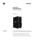
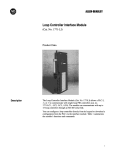
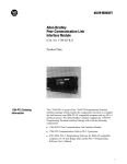
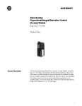
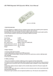
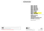
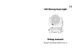
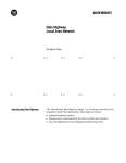
1
Looking for more information?
Visit us on the web at http://www.artisan-scientific.com for more information:
• Price Quotations • Drivers· Technical Specifications. Manuals and Documentation
Artisan Scientific is You~ Source for: Quality New and Certified-Used/Pre:-awned ECJuiflment
• Fast Shipping and DelIve1y
• Tens of Thousands of In-Stock Items
• Equipment Demos
• Hundreds of Manufacturers Supported
• Leasing / Monthly Rentals
Service Center Repairs
Experienced Engineers and Technicians on staff in our
State-of-the-art Full-Service In-House Service Center Facility
• Consignment
InstraView Remote Inspection
Remotely inspect equipment before purchasing with our
Innovative InstraView-website at http://www.instraview.com
We bUy used equipment! We also offer credit for Buy-Backs and Trade-Ins
Sell your excess. underutilized. and idle used equipment. Contact one of our Customer Service Representatives todayl
Talk to a live person: 88EM38-S0URCE fB88-887-68721 I Contact us by email: [email protected] I Visit our website: http://www.artisan-scientific.com
Product Data
Absolute Encoder Module
Absolute Encoder Module
(Cat. No. 1771-DE)
Product Data
Description
The Absolute Encoder Module (cat. no. 1771-DE) is an intelligent module
that provides high-speed response to machine position independently of the
programmable controller scan.
The module is usually used when the following features are required:
absolute-position feedback
high-speed position response based on encoder values
immunity to loss of position from power loss or power interruptions
The absolute encoder module can:
monitor the position of an absolute encoder that has up to 12 bits of
resolution
1
Product Data
Absolute Encoder Module
control up to eight high-current outputs based on comparisons between
encoder position and your preset values
2
Product Data
Absolute Encoder Module
provide throughput of all eight outputs in less than 200 mS
communicate with the programmable controller through block transfers
report the position of an absolute encoder and status of outputs to the
programmable controller
In addition, the module can switch 2A DC per output with no derating
when all outputs are on, allowing 16A continuous per module.
Figure 1 shows the major hardware components on the module.
1
Absolute Encoder Module (cat. no. 1771DE)
You can use the absolute encoder module with any Allen-Bradley
programmable controller that uses block transfer programming in local and
remote 1771 I/O systems.
3
Product Data
Absolute Encoder Module
Some Allen-Bradley programmable controllers compatible with the
module are:
Mini-PLC-2 (cat. no. 1772-LN3)
PLC-2/20 (cat. no. 1772-LP1, -LP2)
PLC-2/30 (cat. no. 1772-LP3)
Mini-PLC-2/15 (cat. no. 1772-LV)
Mini-PLC-2/05 (cat. no. 1772-LS, -LSP)
PLC-3 (cat. no. 1775-L1, -L2)
You can use Allen-Bradley absolute encoders that use up to 12 bits with
the absolute encoder module. Allen-Bradley encoders with the following
bulletin numbers are compatible with the absolute encoder module:
Bulletin 845A
Bulletin 845B
Bulletin 845C
The module is also compatible with absolute encoders that have the
following specifications:
single-ended or differential output
TTL-compatibility (output drivers)
capability of sinking 11 mA (single-ended) or 18 mA (differential) per
channel
natural binary, BCD, or standard Gray code format
We recommend the use of differential output encoders because of their
higher immunity to noise than single-ended output encoders.
Feature Selection
By setting configuration plugs on the left board of the absolute encoder
module you can select:
BCD, natural binary, or standard Gray encoder format
single-ended or differential encoder output signals
direction of shaft rotation that corresponds to increments in the absolute
position of Gray encoders
A configuration plug on the right board lets you select the state of the
outputs if the module loses input power. The plug allows the outputs to:
turn off
remain in their state at loss of input power
4
Product Data
Absolute Encoder Module
Status Indicators
The module has 10 LED indicators (figure 1):
Eight output status indicators (one per output) light when the
corresponding output circuitry is energized
One green ACTIVE indicator lights when the module is powered and
functioning
One red FAULT indicator lights when the module detects a fault and
momentarily lights at power-up
Power Supplies
You need a minimum of two external power supplies: one to power input
circuitry and one to power output devices.
The input circuits of the module require a maximum of 300 mA from a
+5V DC supply. You can also use this +5V supply to power the encoder.
To supply power to the eight outputs, you need at least one +5 to +24V DC
power supply. If you need two different load supply voltages to power your
outputs, you can connect an additional +5 to +24V DC supply to the
module.
Terminal Identification
The encoder signal lines and the power supply for the input circuits are
connected to the terminals on the left board and terminals 17 through 21 on
the right board. The output power supply(ies) and output devices are
connected to terminals 1 through 15 of the right board (figure 2).
5
Product Data
Absolute Encoder Module
2
Terminal Identification
6
Product Data
Absolute Encoder Module
Cabling
We recommend the following Belden cable or its equivalent to connect the
encoder to the module. Use extra twisted pair(s) of wire to connect power
to the encoder.
Encoder Bits
Belden Cable No.
18 AWG
20 AWG
8
9
9775
9875
10
11
9976
12
9776
9877
15
9777
9879
12
Module/Processor
Communication
No. of twisted pairs
in cable
The absolute encoder module and the processor communicate through
block-transfer programming.
Blocktransferwrite Data
You write data to the module in blocks. You can write 5, 10, 15, or 20
words in one block-transfer operation. Each block is associated with two
outputs and is identical to the other blocks in format:
words 1–5
words 6–10
words 11–15
words 16–20
outputs 0 and 1
outputs 2 and 3
outputs 4 and 5
outputs 6 and 7
The first word of each block is a control word. The last four words are
preset words. The format of the write-data words and control word 1 is
shown in figure 3.
7
Product Data
Absolute Encoder Module
3
Format of Blocktransferwrite Data
You can send a maximum of 20 words (four blocks of five words) in one
block-transfer operation. The number of words you send to the module
determines how many outputs it controls.
8
Product Data
Absolute Encoder Module
Control Words
The lower byte of control word 1 is associated with output 0.Its format is
as follows:
Bits 0 through 2 are the comparison bits for output 0, preset A (greater
than, less than, or equal to)
Bits 3 through 5 are the comparison bits for output 0, preset B
Bit 6 is the zero transition (ZT) bit. Set this bit when you want an output
energized during a transition through 0.
Bit 7 is the output enable (OE) bit. This bit is examined along with
comparison bits 0 through 5 and the absolute position of the encoder in
turning on a module’s output. Although comparisons for both presets
may be true, if you don’t set this bit the output is not turned on.
The upper byte of control word 1 is associated with output 1. The format of
this byte is similar to the format of the lower byte:
Bits 10 through 12 are the comparison bits for output 1, preset A.
Bits 13 through 15 are the comparison bits for output 1, preset B.
Bit 16 is the ZT bit.
Bit 17 is the OE bit.
The remaining control words and their corresponding outputs are:
word 6 – outputs 2 and 3
word 11 – outputs 4 and 5
word 16 – outputs 6 and 7
Preset Words
Preset words define the values you choose for turn-on and turn-off points
of the corresponding output. You program them in BCD. Each block of
four preset words is associated with two outputs and is identical in format
to that for outputs 0 and 1:
word 2 – preset A for output 0
word 3 – preset B for output 0
word 4 – preset A for output 1
word 5 – preset B for output 1
9
Product Data
Absolute Encoder Module
Blocktransferread Data
The processor reads data from the module and transfers it to its data table
in two read-data words (figure 4):
The upper byte of word 1 indicates the status of the eight outputs. The
module sets each bit when the corresponding output is turned on.
The format of the lower byte of word 1 (by bit) is:
Bit 7 is the loss-of-input-power bit. It is set when input power is lost; it
is reset when power is restored and bit 6 is reset.
Bit 6 is the write-data-valid bit. It is set at power-up and when the
processor changes from the program to run mode; it is reset when the
module receives valid data in a block transfer-write operation.
Bit 5 is unused.
Bit 4 is the non-BCD preset flag. It is set when any preset is in
non-BCD format.
Bits 3 through 0 make up a code that indicates which preset is not in
BCD format. Refer to the User’s Manual of the module, publication
number 1771-6.5.32, for details of these bits.
Word 2 indicates the current absolute position of the encoder in BCD.
4
Format of BlockTransferRead Data
10
Product Data
Absolute Encoder Module
Maximum Encoder
Shaft Speed
The absolute encoder module can control outputs within a one count
resolution (turn an output on at position 065 and off at position 066) if
shaft speed does not exceed a certain limit. This speed limit depends on the
number of outputs and the number of counts on the encoder. It can be
found from:
S= K/N
where S = maximum shaft speed for one-count resolution; K = a constant;
and N = number of counts on the encoder. The value of K depends on
whether you want to express shaft speed in revolutions per second (rps) or
revolutions per minute (rpm).
If you control:
Then K =
OR
K=
(for rps)
(for rpm)
8 outputs
6 outputs
4 outputs
2 outputs
5000
6493
9009
14,084
300,000
389,610
540,540
845,070
For example, if you control eight outputs with a 0 to 359-count encoder,
and the encoder shaft speed is given in revolutions per minute, the equation
is:
S = 300,000 360
= 833 rpm
The maximum encoder shaft speed at which you can control eight outputs
within a one-count resolution is 833 rpm.
Refer to the User’s Manual for the absolute encoder module (publication
1771-6.5.32) for details on operating the encoder at its maximum speed.
11
Product Data
Absolute Encoder Module
Specifications
Module Location
• Any 1771 I/O chassis;
any 2slot I/O group
Number of Inputs
• Up to 12 encoder input bits per module
Encoder Formats
• BCD
• Natural binary
• Standard Gray
Digital Resolution
• Up to one part in 4,095 with natural binary
and standard Gray encoders
• Up to one part in 999 with BCD encoders
Hightrue Logic
• From totem pole, open collector, or
differential line drivers
• Can select direction of rotation of increasing
position for Gray code encoders
Input Voltage Range and Logic State
Current Requirement (maximum)
• 300 mA
• Number of Outputs
• 8
Output Current Rating
• 2A sourced per output (no derating with all
outputs on)
VA Rating
• 48W per output
• 384W per module
Surge Rating
• 4A for 10ms
Input and Output Isolation
• 1500V RMS
• Logic 1: 2.4V to 5.0V DC
• Logic 0: 0.0V to 0.6V DC
• Selectable: +5 to +24V DC
Input Current per Channel
(sunk by encoder device)
• 800 mA at 5V DC
• 11 mA for singleended drivers
• 18 mA for differential drivers
Maximum Input Frequency
• 50 KHz
Encoder Data Settling Time
• 100ns
New Position Throughput Time
• 200ms
New Writedata Throughput Time
• 3 ms
12
Input Power Supply
• +5V DC "0.25V (total output voltage
tolerance includes line regulation, load
regulation, drift, and ripple)
Output Power Supply
Backplane Current
Output Fuses
• 3A rectifier fuses (Littelfuse 322003,
Buss GBB003, or equivalent)
Environmental Conditions
• Operating Temperature
0 to 60° C (32 to 140°F)
• Storage Temperature
40 to 85° C (40 to 185° F)
• Relative Humidity
5 to 95% (without condensation)
Keying (for slot 0 only)
• Between 2 and 4
• Between 26 and 28
Product Data
Absolute Encoder Module
With offices in major cities worldwide
WORLD
HEADQUARTERS
Allen-Bradley
1201 South Second Street
Milwaukee, WI 53204 USA
Tel: (1) 414 382-2000
Telex: 43 11 016
FAX: (1) 414 382-4444
EUROPE/MIDDLE
EAST/AFRICA
HEADQUARTERS
Allen-Bradley Europe B.V.
Amsterdamseweg 15
1422 AC Uithoorn
The Netherlands
Tel: (31) 2975/43500
Telex: (844) 18042
FAX: (31) 2975/60222
Publication 1771-2.80 — November, 1985
As a subsidiary of Rockwell International, one of the world’s largest technology
companies — Allen-Bradley meets today’s challenges of industrial automation with over
85 years of practical plant-floor experience. More than 11,000 employees throughout the
world design, manufacture and apply a wide range of control and automation products
and supporting services to help our customers continuously improve quality, productivity
and time to market. These products and services not only control individual machines but
integrate the manufacturing process, while providing access to vital plant floor data that
can be used to support decision-making throughout the enterprise.
ASIA/PACIFIC
HEADQUARTERS
Allen-Bradley (Hong Kong)
Limited
Room 1006, Block B, Sea
View Estate
28 Watson Road
Hong Kong
Tel: (852) 887-4788
Telex: (780) 64347
FAX: (852) 510-9436
CANADA
HEADQUARTERS
Allen-Bradley Canada
Limited
135 Dundas Street
Cambridge, Ontario N1R
5X1
Canada
Tel: (1) 519 623-1810
FAX: (1) 519 623-8930
LATIN AMERICA
HEADQUARTERS
Allen-Bradley
1201 South Second Street
Milwaukee, WI 53204 USA
Tel: (1) 414 382-2000
Telex: 43 11 016
FAX: (1) 414 382-2400
PN 955096-77
Printed in USA
13
Looking for more information?
Visit us on the web at http://www.artisan-scientific.com for more information:
• Price Quotations • Drivers· Technical Specifications. Manuals and Documentation
Artisan Scientific is You~ Source for: Quality New and Certified-Used/Pre:-awned ECJuiflment
• Fast Shipping and DelIve1y
• Tens of Thousands of In-Stock Items
• Equipment Demos
• Hundreds of Manufacturers Supported
• Leasing / Monthly Rentals
Service Center Repairs
Experienced Engineers and Technicians on staff in our
State-of-the-art Full-Service In-House Service Center Facility
• Consignment
InstraView Remote Inspection
Remotely inspect equipment before purchasing with our
Innovative InstraView-website at http://www.instraview.com
We bUy used equipment! We also offer credit for Buy-Backs and Trade-Ins
Sell your excess. underutilized. and idle used equipment. Contact one of our Customer Service Representatives todayl
Talk to a live person: 88EM38-S0URCE fB88-887-68721 I Contact us by email: [email protected] I Visit our website: http://www.artisan-scientific.com