1
Programmable Terminal
NA-series
Software
User’s Manual
NA5-15W101
NA5-12W101
NA5-9W001
NA5-7W001
V118-E1-02
OMRON, 2014
All rights reserved. No part of this publication may be reproduced, stored in a retrieval system, or transmitted, in
any form, or by any means, mechanical, electronic, photocopying, recording, or otherwise, without the prior written
permission of OMRON.
No patent liability is assumed with respect to the use of the information contained herein. Moreover, because
OMRON is constantly striving to improve its high-quality products, the information contained in this manual is
subject to change without notice. Every precaution has been taken in the preparation of this manual. Nevertheless, OMRON assumes no responsibility for errors or omissions. Neither is any liability assumed for damages
resulting from the use of the information contained in this publication.
Trademarks
• Sysmac and SYSMAC are trademarks or registered trademarks of OMRON Corporation in Japan and other
countries for OMRON factory automation products.
• Windows, Windows XP, Windows Vista, Windows 7, Windows 8, Excel, and Visual Basic are either registered
trademarks or trademarks of Microsoft Corporation in the USA and other countries.
• EtherCAT® is registered trademark and patented technology, licensed by Beckhoff Automation GmbH, Germany.
• ODVA, CIP, CompoNet, DeviceNet, and EtherNet/IP are trademarks of ODVA.
• The SD and SDHC logos are trademarks of SD-3C, LLC.
• Portions of this software are copyright 2014 The FreeType Project (www.freetype.org). All rights reserved.
Other company names and product names in this document are the trademarks or registered trademarks of their
respective companies.
Introduction
Introduction
Thank you for purchasing an NA-series Programmable Terminal.
This manual contains information that is necessary to use the NA-series Programmable Terminal.
Please read this manual and make sure you understand the functionality and performance of the
NA-series Programmable Terminal before you attempt to use it in a control system.
Keep this manual in a safe place where it will be available for reference during operation.
Intended Audience
This manual is intended for the following personnel, who must also have knowledge of electrical systems (an electrical engineer or the equivalent).
• Personnel in charge of introducing FA systems.
• Personnel in charge of designing FA systems.
• Personnel in charge of installing and maintaining FA systems.
• Personnel in charge of managing FA systems and facilities.
Applicable Products
This manual covers the following products.
• NA-series Programmable Terminals
NA Series Programmable Terminal Software User’s Manual (V118)
1
Relevant Manuals
Relevant Manuals
The basic information required to use an NA-series PT is provided in the following three manuals.
• NA-series Programmable Terminal Hardware User’s Manual (Cat. No. V117)
• NA-series Programmable Terminal Software User’s Manual (Cat. No. V118)
• NA-series Programmable Terminal Device Connection User’s Manual (Cat. No. V119)
Operations are performed from the Sysmac Studio Automation Software.
Refer to the Sysmac Studio Version 1 Operation Manual (Cat. No. W504) for information on the Sysmac Studio.
Other manuals are necessary for specific system configurations and applications.
The following manual is also available to walk you through installations and operations up to starting
actual operation using simple examples.
Refer to it as required.
• NA-series Programmable Terminal Startup Guide Manual (Cat. No. V120)
2
NA Series Programmable Terminal Software User’s Manual (V118)
Manual Structure
Manual Structure
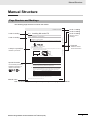
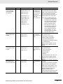
Page Structure and Markings
The following page structure is used in this manual.
Installing NA-series PTs
Level 1 heading
Level 2 heading
Level 3 heading
Installation in a Control Panel
Give the current
headings.
3 Installation and Wiring
Level 2 heading
3-3-1
Installation in a Control Panel
The NA-series PT is installed by embedding it in a control panel. Panel Mounting Brackets and a Phillips screwdriver are
required to mount the NA-series PT. The required number of Panel Mounting Brackets are included with the NA-series PT.
3-3 Installing NA-series PTs
Level 3 heading
3-3
3
Panel Mounting Bracket
Use the following installation procedure.
1
Open a hole in which to embed the NA-series PT with the following dimensions and insert the
NA-series PT from the front side of the panel.
Indicates a procedure.
Vertical
Horizontal
3-3-1 Installation in a Control Panel
A step in a procedure
Phillips screwdriver
Page tab
Gives the number
of the main section.
Recommended panel thickness: 1.6 to 6.0 mm
Model
NA5-15W
392 +1/-0 × 268 +1/-0 mm (horizontal × vertical)
NA5-12W
310 +1/-0 × 221 +1/-0 mm (horizontal × vertical)
NA5-9W
261 +1/-0 × 166 +1/-0 mm (horizontal × vertical)
NA5-7W
197 + 0.5/-0 × 141 +0.5/-0 mm (horizontal × vertical)
Special information
Icons indicate precautions,
additional information, or
reference information.
Dimensions
Additional Information
You can use an NS-USBEXT-1M USB Relay Cable to extend the USB slave connector on the
back panel of the NA-series PT to the front surface of a control panel. If you use the USB Relay
Cable, open a hole with the following dimensions and install the Cable.
2
Attach the panel mounting brackets from the back of the panel as shown in the following figure.
The number of mounting brackets depends on the size of the NA-series PT, as shown in the following
table. Refer to Bracket Mounting Locations for Different NA-series PT Sizes on page 3-8, below.
Model
NA5-15W
NA5-12W
NA5-9W
NA5-7W
Number of Panel Mounting Brackets
8 locations
6 locations
4 locations
4 locations
Catch the brackets in the mounting holes in the NA-series PT, pull forward lightly, and then use
a Phillips screwdriver to tighten the screws and secure the NA-series PT to the panel, which will
be held between the mounting brackets and the NA-series PT.
Manual name
NA Series Programmable Terminal Hardware User’s Manual (V117)
3-5
Note This illustration is provided only as a sample. It may not literally appear in this manual.
NA Series Programmable Terminal Software User’s Manual (V118)
3
Manual Structure
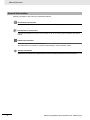
Special Information
Special information in this manual is classified as follows:
Precautions for Safe Use
Precautions on what to do and what not to do to ensure safe usage of the product.
Precautions for Correct Use
Indicates precautions on what to do and what not to do to ensure proper operation and performance.
Additional Information
Additional information to read as required.
This information is provided to increase understanding or make operation easier.
Version Information
Information on differences in specifications and functionality with different versions is given.
4
NA Series Programmable Terminal Software User’s Manual (V118)
Sections in this Manual
Sections in this Manual
1
Introduction to the NA-series
Programmable Terminals
10
Connecting to HMIs
from External Devices
2
Basic Sysmac Studio
Operations
11
Other Functions
3
HMI Configuration
and Setup
A
Appendices
4
Creating the HMI
Application
I
5
Objects
6
Connecting to the HMI
1
10
2
11
3
A
4
I
5
Index
6
7
8
9
7
Debugging
8
Synchronizing Projects
9
Reusing Objects
NA Series Programmable Terminal Software User’s Manual (V118)
5
Sections in this Manual
6
NA Series Programmable Terminal Software User’s Manual (V118)
CONTENTS
Introduction .............................................................................................................. 1
Relevant Manuals..................................................................................................... 2
Manual Structure...................................................................................................... 3
Sections in this Manual ........................................................................................... 5
Terms and Conditions Agreement ........................................................................11
Safety Precautions................................................................................................. 13
Precautions for Safe Use ...................................................................................... 15
Precautions for Correct Use ................................................................................. 18
Regulations and Standards .................................................................................. 19
Related Manuals..................................................................................................... 21
Terminology............................................................................................................ 25
Revision History..................................................................................................... 26
Section 1
1-1
Introduction to the NA-series Programmable Terminals
NA-series Programmable Terminals .................................................................................... 1-2
1-1-1
1-2
How HMIs Operate................................................................................................................. 1-4
1-2-1
1-2-2
1-2-3
1-2-4
1-2-5
1-2-6
1-2-7
1-2-8
1-2-9
1-3
HMI Software Configuration........................................................................................................ 1-4
HMI Projects ............................................................................................................................... 1-4
Pages ......................................................................................................................................... 1-4
Objects........................................................................................................................................ 1-5
Memory Specifications for Connected Devices .......................................................................... 1-6
Events......................................................................................................................................... 1-7
Subroutines................................................................................................................................. 1-8
Functions Shared by the Entire HMI Project............................................................................... 1-9
Data That Retained When Power Is Turned OFF....................................................................... 1-9
Operating Procedure for HMIs ........................................................................................... 1-10
1-3-1
1-3-2
Section 2
2-1
Features...................................................................................................................................... 1-2
Overall Procedure..................................................................................................................... 1-10
Procedure Details ......................................................................................................................1-11
Basic Sysmac Studio Operations
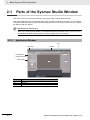
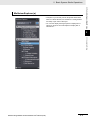
Parts of the Sysmac Studio Window ................................................................................... 2-2
2-1-1
Application Window .................................................................................................................... 2-2
2-2
Menu Command Structure.................................................................................................... 2-6
2-3
Basic Editing Operations...................................................................................................... 2-8
NA Series Programmable Terminal Software User’s Manual (V118)
7
2-4
Sysmac Studio Settings and Operations .......................................................................... 2-10
2-4-1
2-4-2
2-4-3
2-4-4
2-4-5
2-4-6
2-4-7
2-5
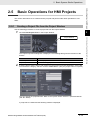
Basic Operations for HMI Projects..................................................................................... 2-13
2-5-1
2-5-2
2-5-3
Section 3
3-1
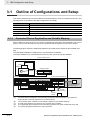
Outline of Configurations and Setup ................................................................................... 3-2
Types of Connected Devices ...................................................................................................... 3-3
Connected Devices in the Current Project .................................................................................. 3-3
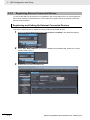
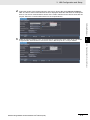
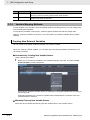
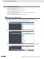
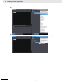
Registering External Connected Devices.................................................................................... 3-4
Mapping Variables ................................................................................................................. 3-7
3-3-1
3-3-2
3-3-3
3-4
Connected Device Registration and Variable Mapping............................................................... 3-2
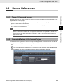
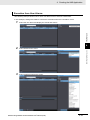
Device References................................................................................................................. 3-3
3-2-1
3-2-2
3-2-3
3-3
Creating a Project File from the Project Window ...................................................................... 2-13
Adding an HMI to an Existing Project........................................................................................ 2-14
Changing Devices ..................................................................................................................... 2-15
HMI Configuration and Setup
3-1-1
3-2
Setting Parameters ................................................................................................................... 2-10
Programming............................................................................................................................. 2-10
Library Functions....................................................................................................................... 2-11
Operations for Debugging ......................................................................................................... 2-11
Communications ....................................................................................................................... 2-11
Security Measures .................................................................................................................... 2-11
Online Help ............................................................................................................................... 2-12
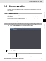
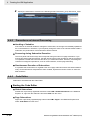
Mapping Variables....................................................................................................................... 3-7
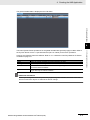
Opening the Variable Mapping Tab Page and Tab Page Parts ................................................... 3-7
Variable Mapping Methods.......................................................................................................... 3-8
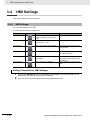
HMI Settings......................................................................................................................... 3-10
3-4-1
3-4-2
3-4-3
3-4-4
3-4-5
3-4-6
3-4-7
HMI Settings.............................................................................................................................. 3-10
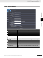
Device Settings ......................................................................................................................... 3-11
TCP/IP Settings......................................................................................................................... 3-12
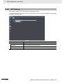
FTP Settings ............................................................................................................................. 3-13
NTP Settings ............................................................................................................................. 3-14
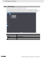
FINS Settings ............................................................................................................................ 3-15
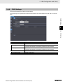
VNC Settings............................................................................................................................. 3-16
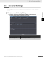
3-5
Security Settings ................................................................................................................. 3-17
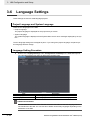
3-6
Language Settings .............................................................................................................. 3-18
3-7
HMI Clock ............................................................................................................................. 3-19
3-8
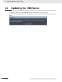
Updating the HMI Name ...................................................................................................... 3-20
3-9
Write Protecting the HMI ..................................................................................................... 3-21
3-10 Clear All Memory ................................................................................................................. 3-22
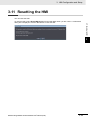
3-11 Resetting the HMI ................................................................................................................ 3-23
Section 4
4-1
Creating the HMI Application
Registering Variables ............................................................................................................ 4-2
4-1-1
4-1-2
4-1-3
4-1-4
4-1-5
4-1-6
4-2
Creating Pages .................................................................................................................... 4-11
4-2-1
4-2-2
4-2-3
4-2-4
8
Variables ..................................................................................................................................... 4-2
Registering Global Variables....................................................................................................... 4-2
Registering External Variables .................................................................................................... 4-4
Attributes and Entry Methods for Global Variables ..................................................................... 4-5
System-defined Variables ........................................................................................................... 4-8
Subroutine Variables ................................................................................................................. 4-10
Displaying Pages ...................................................................................................................... 4-12
Registering Pages..................................................................................................................... 4-12
Page Property Settings ............................................................................................................. 4-14
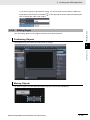
Editing Pages ............................................................................................................................ 4-15
NA Series Programmable Terminal Software User’s Manual (V118)
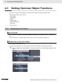
4-3
Setting Common Object Functions ................................................................................... 4-18
4-3-1
4-3-2
4-3-3
4-3-4
4-3-5
4-3-6
4-3-7
4-4
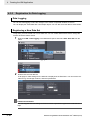
Registering User Alarms........................................................................................................... 4-18
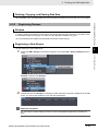
Registration for Data Logging ................................................................................................... 4-20
Registering Recipes.................................................................................................................. 4-21
Setting Global Events and Corresponding Actions................................................................... 4-22
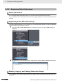
Registering Global Subroutines ................................................................................................ 4-24
Setting Up Resources............................................................................................................... 4-25
Setting Up IAG Resources........................................................................................................ 4-26
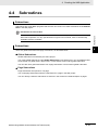
Subroutines.......................................................................................................................... 4-27
4-4-1
4-4-2
4-4-3
4-4-4
Subroutine Execution................................................................................................................ 4-28
Precautions on Internal Processing .......................................................................................... 4-32
Code Editor............................................................................................................................... 4-32
Differences in Language Specifications.................................................................................... 4-33
4-5
Search and Replace ............................................................................................................ 4-34
4-6
Building ................................................................................................................................ 4-35
4-6-1
4-6-2
4-7
Offline Comparison ............................................................................................................. 4-36
Section 5
5-1
Objects
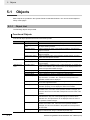
Objects ................................................................................................................................... 5-2
5-1-1
5-1-2
5-1-3
5-2
Building ..................................................................................................................................... 4-35
Build Operation ......................................................................................................................... 4-35
Object List................................................................................................................................... 5-2
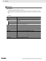
Object Attributes ......................................................................................................................... 5-3
Using Objects ............................................................................................................................. 5-7
Examples of Using Objects ................................................................................................ 5-11
5-2-1
5-2-2
5-2-3
5-2-4
Section 6
Displaying a PDF File ................................................................................................................5-11
Displaying a User Alarm ........................................................................................................... 5-13
Displaying a Trend Graph......................................................................................................... 5-15
Using a Recipe ......................................................................................................................... 5-17
Connecting to the HMI
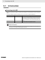
6-1
Introduction............................................................................................................................ 6-2
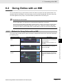
6-2
Going Online with an HMI ..................................................................................................... 6-3
6-2-1
6-2-2
6-2-3
6-2-4
6-2-5
6-2-6
Section 7
7-1
Methods for Going Online with an HMI....................................................................................... 6-3
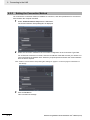
Setting the Connection Method .................................................................................................. 6-4
Online Connection ...................................................................................................................... 6-5
Going Online after Checking the Connection Method ................................................................ 6-6
Going Offline............................................................................................................................... 6-6
Confirming Serial IDs.................................................................................................................. 6-7
Debugging
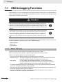
HMI Debugging Functions .................................................................................................... 7-2
7-1-1
7-1-2
7-1-3
7-1-4
7-1-5
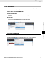
Watch Tab Page ......................................................................................................................... 7-2
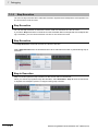
Breakpoints................................................................................................................................. 7-3
Step Execution............................................................................................................................ 7-4
Offline Debugging with Only the HMI Simulator ......................................................................... 7-6
Offline Debugging with the Controller Simulator......................................................................... 7-7
NA Series Programmable Terminal Software User’s Manual (V118)
9
Section 8
Synchronizing Projects
8-1
Synchronizing Projects......................................................................................................... 8-2
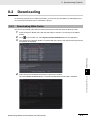
8-2
Downloading .......................................................................................................................... 8-5
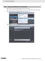
8-2-1
8-2-2
8-3
Downloading While Online .......................................................................................................... 8-5
Using Storage Media for Downloading........................................................................................ 8-6
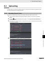
Uploading ............................................................................................................................... 8-9
8-3-1
8-3-2
8-3-3
Section 9
Uploading Projects Online........................................................................................................... 8-9
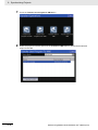
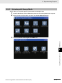
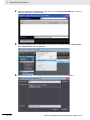
Uploading with Storage Media .................................................................................................. 8-11
Relinking Internal Devices......................................................................................................... 8-15
Reusing Objects
9-1
Reusing Objects .................................................................................................................... 9-2
9-2
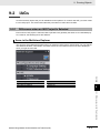
IAGs ........................................................................................................................................ 9-3
9-2-1
9-2-2
9-2-3
9-3
Differences when an IAG Project Is Selected ............................................................................. 9-3
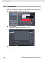
Creating an IAG .......................................................................................................................... 9-8
Using IAGs ................................................................................................................................ 9-11
Custom Objects ................................................................................................................... 9-14
9-3-1
9-3-2
9-3-3
9-3-4
Section 10
Objects That You Can Register as Custom Objects ................................................................. 9-14
Creating Custom Objects .......................................................................................................... 9-14
Deleting Custom Objects .......................................................................................................... 9-17
Using Custom Objects .............................................................................................................. 9-18
Connecting to HMIs from External Devices
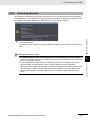
10-1 Accessing an HMI from an External Device ...................................................................... 10-2
10-1-1 VNC........................................................................................................................................... 10-2
10-1-2 FTP ........................................................................................................................................... 10-3
Section 11
Other Functions
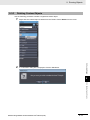
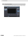
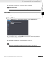
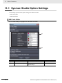
11-1 Sysmac Studio Option Settings ......................................................................................... 11-2
Appendices
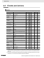
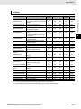
A-1 Events and Actions ...............................................................................................................A-2
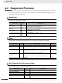
A-2 Supported Formats................................................................................................................A-4
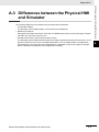
A-3 Differences between the Physical HMI and Simulator .......................................................A-5
A-4 Version Upgrade History.......................................................................................................A-6
A-4-1
A-4-2
A-4-3
Version Upgrade History for Sysmac Studio and Runtime..........................................................A-6
Version Upgrade History for Sysmac Studio Only.......................................................................A-6
Sysmac Studio Corresponding Versions .....................................................................................A-6
Index
10
NA Series Programmable Terminal Software User’s Manual (V118)
Terms and Conditions Agreement
Terms and Conditions Agreement
Warranty, Limitations of Liability
Warranties
Exclusive Warranty
Omron’s exclusive warranty is that the Products will be free from defects in materials and workmanship for a period of twelve months from the date of sale by Omron (or such other period expressed in
writing by Omron). Omron disclaims all other warranties, express or implied.
Limitations
OMRON MAKES NO WARRANTY OR REPRESENTATION, EXPRESS OR IMPLIED, ABOUT
NON-INFRINGEMENT, MERCHANTABILITY OR FITNESS FOR A PARTICULAR PURPOSE OF
THE PRODUCTS. BUYER ACKNOWLEDGES THAT IT ALONE HAS DETERMINED THAT THE
PRODUCTS WILL SUITABLY MEET THE REQUIREMENTS OF THEIR INTENDED USE.
Omron further disclaims all warranties and responsibility of any type for claims or expenses based
on infringement by the Products or otherwise of any intellectual property right.
Buyer Remedy
Omron’s sole obligation hereunder shall be, at Omron’s election, to (i) replace (in the form originally
shipped with Buyer responsible for labor charges for removal or replacement thereof) the non-complying Product, (ii) repair the non-complying Product, or (iii) repay or credit Buyer an amount equal
to the purchase price of the non-complying Product; provided that in no event shall Omron be
responsible for warranty, repair, indemnity or any other claims or expenses regarding the Products
unless Omron’s analysis confirms that the Products were properly handled, stored, installed and
maintained and not subject to contamination, abuse, misuse or inappropriate modification. Return of
any Products by Buyer must be approved in writing by Omron before shipment. Omron Companies
shall not be liable for the suitability or unsuitability or the results from the use of Products in combination with any electrical or electronic components, circuits, system assemblies or any other materials or substances or environments. Any advice, recommendations or information given orally or in
writing, are not to be construed as an amendment or addition to the above warranty.
See http://www.omron.com/global/ or contact your Omron representative for published information.
Limitation on Liability; Etc
OMRON COMPANIES SHALL NOT BE LIABLE FOR SPECIAL, INDIRECT, INCIDENTAL, OR CONSEQUENTIAL DAMAGES, LOSS OF PROFITS OR PRODUCTION OR COMMERCIAL LOSS IN ANY
WAY CONNECTED WITH THE PRODUCTS, WHETHER SUCH CLAIM IS BASED IN CONTRACT,
WARRANTY, NEGLIGENCE OR STRICT LIABILITY.
Further, in no event shall liability of Omron Companies exceed the individual price of the Product on
which liability is asserted.
NA Series Programmable Terminal Software User’s Manual (V118)
11
Terms and Conditions Agreement
Application Considerations
Suitability of Use
Omron Companies shall not be responsible for conformity with any standards, codes or regulations
which apply to the combination of the Product in the Buyer’s application or use of the Product. At
Buyer’s request, Omron will provide applicable third party certification documents identifying ratings
and limitations of use which apply to the Product. This information by itself is not sufficient for a complete determination of the suitability of the Product in combination with the end product, machine, system, or other application or use. Buyer shall be solely responsible for determining appropriateness of
the particular Product with respect to Buyer’s application, product or system. Buyer shall take application responsibility in all cases.
NEVER USE THE PRODUCT FOR AN APPLICATION INVOLVING SERIOUS RISK TO LIFE OR
PROPERTY WITHOUT ENSURING THAT THE SYSTEM AS A WHOLE HAS BEEN DESIGNED TO
ADDRESS THE RISKS, AND THAT THE OMRON PRODUCT(S) IS PROPERLY RATED AND
INSTALLED FOR THE INTENDED USE WITHIN THE OVERALL EQUIPMENT OR SYSTEM.
Programmable Products
Omron Companies shall not be responsible for the user’s programming of a programmable Product, or
any consequence thereof.
Disclaimers
Performance Data
Data presented in Omron Company websites, catalogs and other materials is provided as a guide for
the user in determining suitability and does not constitute a warranty. It may represent the result of
Omron’s test conditions, and the user must correlate it to actual application requirements. Actual performance is subject to the Omron’s Warranty and Limitations of Liability.
Change in Specifications
Product specifications and accessories may be changed at any time based on improvements and other
reasons. It is our practice to change part numbers when published ratings or features are changed, or
when significant construction changes are made. However, some specifications of the Product may be
changed without any notice. When in doubt, special part numbers may be assigned to fix or establish
key specifications for your application. Please consult with your Omron’s representative at any time to
confirm actual specifications of purchased Product.
Errors and Omissions
Information presented by Omron Companies has been checked and is believed to be accurate; however, no responsibility is assumed for clerical, typographical or proofreading errors or omissions.
12
NA Series Programmable Terminal Software User’s Manual (V118)
Safety Precautions
Safety Precautions
Definition of Precautionary Information
The following notation is used in this manual to provide precautions required to ensure safe usage of
the NA-series Programmable Terminal. The safety precautions that are provided are extremely important to safety. Always read and heed the information provided in all safety precautions.
The following notation is used.
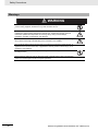
WARNING
Caution
Indicates a potentially hazardous situation which, if
not avoided, could result in mild or moderate injury or
at the worst, serious injury or death. Additionally,
there may be severe property damage.
Indicates a potentially hazardous situation which, if not
avoided, may result in minor or moderate injury, or
property damage.
Precautions for Safe Use
Indicates precautions on what to do and what not to do to ensure safe usage of the product.
Precautions for Correct Use
Indicates precautions on what to do and what not to do to ensure proper operation and performance.
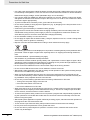
Symbols
The circle and slash symbol indicates operations that you must not do.
The specific operation is shown in the circle and explained in text.
This example indicates prohibiting disassembly.
The triangle symbol indicates precautions (including warnings).
The specific operation is shown in the triangle and explained in text.
This example indicates a general precaution.
NA Series Programmable Terminal Software User’s Manual (V118)
13
Safety Precautions
Warnings
WARNING
Do not attempt to take the NA Unit apart and do not touch the product inside while the
power is being supplied. Otherwise it may result in electric shock.
Always ensure that the personnel in charge confirm that installation, inspection, and
maintenance were properly performed for the NA Unit. “Personnel in charge” refers to
individuals qualified and responsible for ensuring safety during machine design,
installation, operation, maintenance, and disposal.
Ensure that installation and post-installation checks are performed by personnel in charge
who possess a thorough understanding of the machinery to be installed.
Do not use the input functions such as the touch panel or function keys of the NA Unit, in
applications that involve human life, in applications that may result in serious injury, or for
emergency stop switches.
Do not attempt to disassemble, repair, or modify the NA Unit. It may cause NA Unit to lose
its safety function.
Never press two points or more on the touch panel of the NA Unit at a time. Touching two
points or more interrupts normal touch panel operations.
14
NA Series Programmable Terminal Software User’s Manual (V118)
Precautions for Safe Use
Precautions for Safe Use
• When unpacking the NA Unit, check carefully for any external scratches or other damages. Also,
shake the NA Unit gently and check for any abnormal sound.
• The NA Unit must be installed in a control panel.
• The mounting panel must be between 1.6 and 6.0 mm thick. Tighten the Mounting Brackets evenly to
a torque of between 0.5 and 0.6 N·m to maintain water and dust resistance. If the tightening torque
exceeds the specified value, or the tightening is not even, deformation of the front panel may occur.
What is more, make sure the panel is not dirty or warped and that it is strong enough to hold the NA
Unit.
• Do not let metal particles enter the NA Unit when preparing the panel.
• Turn OFF the power supply before connecting or disconnecting cables.
• Periodically check the installation conditions in applications where the NA Unit is subject to contact
with oil or water.
• Be certain to use the cables with lock mechanism such as serial cable or the Ethernet cable after
confirming if it is securely locked.
• Do not touch the packaging part of the circuit board with your bare hands. Discharge any static electricity from your body before handling the board.
• Do not use volatile solvents such as benzene and thinners or chemical cloths.
• Water and oil resistance will be lost if the front sheet is torn or is peeling off. Do not use the NA Unit,
if the front sheet is torn or is peeling off.
• As the rubber packing will deteriorate, shrink, or harden depending on the operating environment,
periodical inspection is necessary.
• Confirm the safety of the system before turning ON or OFF the power supply, or pressing the reset
switch.
• The whole system may stop depending on how the power supply is turned ON or OFF. Turn ON/OFF
the power supply according to the specified procedure.
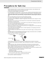
• Operate DIP switch according to the following way.
Correct technique
Incorrect technique
Back of the case
DIP switch
The DIP switch may break if it is levered with a tool against the case as shown in the figure.
• Once the DIP switch settings are changed, reset by pressing the reset switch, or restart the power
supply.
• Initialize the project, after confirming that existing project is backed up at the Sysmac Studio.
• When changing the password, do not reset or turn OFF the power supply until the writing is completed. A failure to store the password may cause the project to fail to function.
• While uploading or downloading a project or a system program, do not perform the operations as follows. Such operations may corrupt the project or the system program:
• Turning OFF the power supply of the NA Unit
• Resetting the NA Unit.
• Removing the USB devices or SD card.
• Disconnecting the cable between a support tool and the NA Unit.
• Do not connect an AC power supply to the DC power terminals.
• Do not perform a dielectric strength test.
NA Series Programmable Terminal Software User’s Manual (V118)
15
Precautions for Safe Use
• Use a DC power with a slight voltage fluctuation and that will provide a stable output even if the input
is momentarily interrupted for 10 ms. Also use the one with reinforced insulation or double insulation.
Rated Power Supply Voltage: 24VDC (Allowable range 19.2 to 28.8VDC)
• Use a power cable with AWG#12 to #22 thick (0.35mm2 to 3.31mm2). Peel the coating 7mm length
and tighten the terminal screw with the torque in the range of 0.5 to 0.6 N·m. Also confirm if the terminal screw is tighten appropriately.
• To prevent malfunctions caused by noise, ground the NA Unit correctly.
• Do not use any battery if strong impact is applied to it (e.g. by dropping on the floor) because such a
battery may cause a leakage.
• Confirm the type of the battery to install the battery properly.
• Apply power for at least five minutes before changing the battery. Mount a new battery within five
minutes after turning OFF the power supply. If power is not supplied for at least five minutes, the
clock data may be lost. Check the clock data after changing the battery.
• Do not dismantle a battery nor let it short-circuit.
• Do not apply an impact with the lithium battery, charge it, dispose it into a fire, or heat it. Doing either
of them may cause an ignition or a bursting.
• Dispose of the NA Units and batteries according to local ordinances as they apply.
• The following precaution must be displayed on all products containing lithium primary batteries with a
perchlorate content of 6ppb or higher when exporting them to or shipping them through California,
USA.
Perchlorate Material - special handling may apply.
See www.dtsc.ca.gov/hazardouswaste/perchlorate
The NA-Series contains a lithium primary battery with a perchlorate content of 6ppb or higher. When
exporting a product containing the NA-Series to or shipping such a product through California, USA,
label all packing and shipping containers appropriately.
• Do not connect the USB devices in the environment subject to the strong vibration.
• Do not connect USB devices which are not allowed to connect to NA Unit.
• Start actual system application only after checking normal operation of the system including storage
devices such as USB memory and SD card.
• When connecting peripheral devices which do not meet the performance level of the NA Unit for
noise and static electricity, ensure sufficient countermeasures against noise and static electricity during installation of the peripheral devices to the NA Unit.
• Do not carry out the following operations when accessing USB devices or SD card:
• Turning OFF the power supply of the NA Unit
• Press the Reset switch of the NA Unit
• Pull out the USB devices or SD card
• When using the No. 6 pin of the serial port connector for a voltage of DC+5V, make sure the supply
equipment's current capacity is below 250mA before using it. The DC+5V voltage output of the NA
Unit is +5V±5%, and the maximum current is 250mA.
• To ensure the system's safety, make sure to incorporate a program that call periodically signals during the operation at connected device side and can confirm the normal functionality of the NA Unit
before running the system.
• Start actual system application only after sufficiently checking project, subroutine and the operation of
the program at the connected device side.
• To use numeric input functions safely, always make maximum and minimum limit settings.
• Do not press the touch panel with a force greater than 30 N.
• Do not use hard or pointed objects to operate or scrub the screen, otherwise the surface of the
screen may be damaged.
16
NA Series Programmable Terminal Software User’s Manual (V118)
Precautions for Safe Use
• The deterioration over time may cause the touch points to move on the touch panel. Calibrate the
touch panel periodically.
• A touch position detection error of approximately 20 pixels may occur due to the precision of the
touch panel. Always take this into account when positioning objects on the panel so adjoining objects
will not be activated by mistake.
• Confirm the safety of the system before pressing the touch panel.
• Do not accidentally press the touch panel when the backlight is not lit or when the display does not
appear or is too dark to identify visually.
• You can change the brightness by changing the setting such as in the system menu or by downloading project.
If the brightness is set to very dark, it causes flickering or unreadable screen. Additionally, the brightness can be restored by transferring the project again after setting the property of the brightness
appropriately.
In a case of the applications where end users can control the brightness, create the applications so
as keeping on operations by such as assigning the function which restores the brightness to one of
function keys, if necessary.
• Signals from the touch panel may not be entered if the touch panel is pressed consecutively at high
speed. Make sure to go on the next operation after confirming that the NA Unit has detected the input
of the touch panel.
• The function keys have the restrictions as follows:
• Using both anti-reflection sheet and protective cover interrupts the normal function key operation.
Do not use them together.
• When you use gloves or others, the function keys may not work correctly depending on the material and thickness of the gloves. Take actual conditions of the gloves usage into considerations
prior to the system startup to perform the confirmation.
• The function keys do not work when covered with water. Remove the water completely before
use.
NA Series Programmable Terminal Software User’s Manual (V118)
17
Precautions for Correct Use
Precautions for Correct Use
Do not install or store the NA Unit in any of the following locations:
• Locations subject to severe changes in temperature
• Locations subject to temperatures or humidity outside the range specified in the specifications
• Locations subject to condensation as the result of high humidity
• Locations subject to corrosive or flammable gases
• Locations subject to strong shock or vibration
• Locations outdoors subject to direct wind and rain
• Locations subject to strong ultraviolet light
• Locations subject to dust
• Locations subject to direct sunlight
• Locations subject to splashing oil or chemicals
Take appropriate and sufficient countermeasures when installing systems in
the following locations:
• Locations subject to static electricity or other forms of noise
• Locations subject to strong electric field or magnetic field
• Locations close to power supply lines
• Locations subject to possible exposure to radioactivity
18
NA Series Programmable Terminal Software User’s Manual (V118)
Regulations and Standards
Regulations and Standards
Conformance to EC Directives
Applicable Directives
• EMC Directive
Concepts
EMC Directive
OMRON devices that comply with EC Directives also conform to the related EMC standards so that
they can be more easily built into other devices or the overall machine. The actual products have
been checked for conformity to EMC standards.*
Whether the products conform to the standards in the system used by the customer, however, must
be checked by the customer. EMC-related performance of the OMRON devices that comply with EC
Directives will vary depending on the configuration, wiring, and other conditions of the equipment or
control panel on which the OMRON devices are installed. The customer must, therefore, perform
the final check to confirm that devices and the overall machine conform to EMC standards.
*
Applicable EMC (Electromagnetic Compatibility) standards are as follows:
EMS (Electromagnetic Susceptibility): EN 61131-2:2007
EMI (Electromagnetic Interference): EN 61131-2:2007
Conformance to EC Directives
The NA-series PTs comply with EC Directives. To ensure that the machine or device in which the
NA-series PT is used complies with EC Directives, the NA-series PT must be installed as follows:
• The NA Unit must be installed within a control panel.
• You must use reinforced insulation or double insulation for the DC power supplies connected to
the NA Unit.
• NA-series PTs that comply with EC Directives also conform to the Common Emission Standard
(EN 61000-6-4). Radiated emission characteristics (10-m regulations) may vary depending on the
configuration of the control panel used, other devices connected to the control panel, wiring, and
other conditions.
You must therefore confirm that the overall machine or equipment complies with EC Directives.
• This is a Class A product (for industrial environments). In a residential environment, it may cause
radio interference, in which case the user may be required to take appropriate measures.
NA Series Programmable Terminal Software User’s Manual (V118)
19
Regulations and Standards
Conformance to KC Standards
Observe the following precaution if you use NA-series PTs in Korea.
Class A Device (Broadcasting Communications Device for Business Use)
This device obtained EMC registration for office use (Class A), and it is intended to be used in places
other than homes. Sellers and/or users need to take note of this.
20
NA Series Programmable Terminal Software User’s Manual (V118)
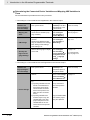
Related Manuals
Related Manuals
The following manuals are related to the NA-series PTs. Use these manuals for reference.
Manual name
Cat. No.
V117
NA-series Programmable Terminal Hardware User’s Manual
Models
NA5-W
NA-series Programmable Terminal Software User’s Manual
V118
NA5-W
NA-series Programmable Terminal
Device Connection
User’s Manual
V119
NA5-W
NA-series Programmable Terminal
Startup Guide
V120
NA5-W
NJ-series CPU Unit
Hardware User’s
Manual
W500
NJ501-
NJ301-
Applications
Learning the specifications and settings required to
install an NA-series
PT and connect
peripheral devices.
Learning about
NA-series PT
pages and object
functions.
Learning the specifications required
to connect devices
to an NA-series
PT.
Learning in concrete terms information required to
install and start the
operation of an
NA-series PT.
Learning the basic
specifications of
the NJ-series CPU
Units, including
introductory information, designing,
installation, and
maintenance.
Mainly hardware
information is provided.
Description
Information is provided on NA-series
PT specifications, part names, installation procedures, and procedures to
connect an NA Unit to peripheral
devices.
Information is also provided on maintenance after operation and troubleshooting.
NA-series PT pages and object functions are described.
Information is provided on connection procedures and setting procedures to connect an NA-series PT to
a Controller or other device.
The part names and installation procedures are described followed by
page creation and transfer procedures with the Sysmac Studio. Also
operation, maintenance, and inspection procedures after the project is
transferred are described. Sample
screen captures are provided as
examples.
An introduction to the entire
NJ-series system is provided along
with the following information on a
Controller built with a CPU Unit.
• Features and system configuration
• Introduction
• Part names and functions
• General specifications
• Installation and wiring
• Inspection and maintenance
Use this manual together with the
NJ-series CPU Unit Software User’s
Manual (Cat. No. W501).
NA Series Programmable Terminal Software User’s Manual (V118)
21
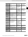
Related Manuals
Manual name
NJ-series CPU Unit
Software User´s
Manual
CJ Series Programmable Controllers
Operation Manual
Cat. No.
W501
Models
NJ501-
NJ301-
W393
CJ1H-CPUH-R
CJ1G/H-CPUH
CJ1G-CPUP
CJ1M-CPU
CJ1G-CPU
CS/CJ/NSJ Series
Programmable Controllers Operation
Manual
W394
CS1G/H-CPUH
CS1G/H-CPU-V1
CS1D-CPUH
CS1D-CPUS
Applications
Learning how to
program and set
up an NJ-series
CPU Unit.
Description
Provides the following information on
a Controller built with an NJ-series
CPU Unit.
Mainly software
information is provided.
• CPU Unit features
Learning the basic
specifications of
the CJ-series
PLCs, including
introductory information, designing,
installation, and
maintenance.
Learning about the
functions of the
CS/CJ-series and
NSJ-series PLCs.
• CPU Unit operation
• Initial settings
• Programming based on IEC
61131-3 language specifications
Use this manual together with the
NJ-series CPU Unit Hardware
User’s Manual (Cat. No. W500).
The following information is provided
on a CJ-series PLC.
• Introduction and features
• System configuration design
• Installation and wiring
• I/O memory allocation
• Troubleshooting
Use this manual together with the
Programming Manual (Cat. No.
W394).
The following information is provided
on a CS/CJ-series or NSJ-series
PLC.
• Programming
• Master function
CJ1H-CPUH-R
• File memory
CJ1G/H-CPUH
• Other functions
CJ1G-CPUP
Use this manual together with the
Operation Manual (CS-series PLCs:
W339, CJ-series PLCs: W393).
CJ1M-CPU
CJ1G-CPU
NSJ-(B)-G5D
CS/CJ/NJ-series
Instructions Reference Manual
W340
NSJ-(B)-M3D
CS1□-CPU--
CJ1□-CPU--
CJ2H-CPU--
NSJ--
CS/CJ Series Programming Consoles
Operation Manual
W341
CQM1H-PRO01
CQM1-PRO01
C200H-PRO27
+CS1W-KS001
22
Learning detailed
information on programming instructions.
Learning the operating procedures
of the Programming Consoles.
Instructions are described in detail.
When programming, use this manual
together with the Operation Manual
(CS-series PLCs: W339, CJ-series
PLCs: W393) and the Programming
Manual (W394).
The operating procedures of the Programming Consoles are described.
When programming, use this manual
together with the Operation Manual
(CS-series PLCs: W339, CJ-series
PLCs: W393), the Programming
Manual (W394), and the Instructions
Reference Manual (W340).
NA Series Programmable Terminal Software User’s Manual (V118)
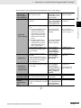
Related Manuals
Manual name
CS/CJ/NSJ Series
Communications
Commands Reference Manual
Cat. No.
W342
Models
CS1G/H-CPUH
CS1G/H-CPU-V1
CS1D-CPUH
CS1D-CPUS
CS1W-SCU-V1
CS1W-SCB-V1
CJ1G/H-CPUH
Applications
Learning detailed
specifications on
the communications instructions
addressed to
CS/CJ-series CPU
Units and
NSJ-series PLCs.
CJ1G-CPUP
CJ1M-CPU
CJ1G-CPU
CJ1W-SCU-V1
CJ-series CJ2 CPU
Unit Hardware User’s
Manual
W472
CJ2H-CPU6-EIP
CJ2H-CPU6
CJ2M-CPU
Learning the hardware specifications of CJ2 CPU
Units.
Description
1) C-mode commands and 2) FINS
commands are described in detail.
Refer to this manual for information
on communications commands
(C-mode commands and FINS commands) addressed to CPU Units.
Note This manual describes communications commands that
are addressed to a CPU Unit.
The communications path is
not relevant. (The communications commands can be
sent through the serial communications port of the CPU
Unit, the communications
port of a Serial Communications Board/Unit, or a communications port on another
Communications Unit.)
The following information is provided
on a CJ2 CPU Unit.
• Introduction and features
• Basic system configuration
• Part names and functions
• Installation and setting procedures
• Troubleshooting
CJ-series CJ2 CPU
Unit Software User’s
Manual
W473
CJ2H-CPU6-EIP
CJ2H-CPU6
CJ2M-CPU
Learning the software specifications of CJ2 CPU
Units.
Use this manual together with the
Software User’s Manual (Cat. No.
W473).
The following information is provided
on a CJ2 CPU Unit.
• CPU Unit operation
• Internal memory
• Programming
• Settings
• Functions built into the CPU Unit
Ethernet Units Operation Manual Construction of Networks
W420
CS1W-ETN21
CJ1W-ETN21
Learning how to
use an Ethernet
Unit.
Use this manual together with the
Hardware User’s Manual (Cat. No.
W472).
Information is provided on the Ethernet Units.
Information is provided on the basic
setup and FINS communications.
Refer to the Communications Commands Reference Manual (Cat. No.
W342) for details on FINS commands that can be sent to
CS/CJ-series CPU Units when using
the FINS communications service.
NA Series Programmable Terminal Software User’s Manual (V118)
23
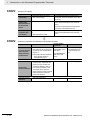
Related Manuals
Manual name
Ethernet Units Operation Manual Construction of
Applications
Cat. No.
W421
CS/CJ-series EtherNet/IP™ Units Operation Manual
W465
Models
CS1W-ETN21
CJ1W-ETN21
CJ2H-CPU6-EIP
CJ2M-CPU3
CS1W-EIP21
CJ1W-EIP21
Sysmac Studio Version 1 Operation
Manual
W504
SYSMAC-SE2
CX-Programmer
Operation Manual
W446
CXONE-ALC-V4
24
CXONE-ALD-V4
Applications
Learning how to
use an Ethernet
Unit.
Learning how to
use the built-in
EtherNet/IP port of
the CJ2 CPU
Units.
Description
Information is provided on constructing host applications, including functions for sending/receiving mail,
socket service, automatic clock
adjustment, FTP server functions,
and FINS communications.
Information is provided on the built-in
EtherNet/IP port and EtherNet/IP
Units.
Basic settings, tag data links, FINS
communications, and other functions
are described.
The operating procedures of the
Sysmac Studio are described.
Learning about the
operating procedures and functions of the
Sysmac Studio.
Learning about the The operating procedures of the
CX-Programmer are described.
CX-Programmer
except for information on function
blocks, ST programming, and
SFC programming.
NA Series Programmable Terminal Software User’s Manual (V118)
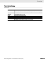
Terminology
Terminology
Term
HMI
PT
NA Series
HMI Project
NA Unit
Download
Upload
IAG collection
Description
A general term for interface devices that indicates both hardware and software elements. In
this manual, “HMI” refers to an OMRON Sysmac-brand product unless otherwise specified.
The hardware elements of the HMI.
The NA Series of Programmable Terminals and peripheral devices.
A Sysmac Studio project for an HMI.
An NA-series Programmable Terminal.
Transferring data from the Sysmac Studio to an HMI.
Transferring the project from an HMI to the Sysmac Studio.
When you provide IAGs, you provide them as IAG collections. IAGs are also imported as
IAG collections. An IAG collection contains one or more IAGs.
NA Series Programmable Terminal Software User’s Manual (V118)
25
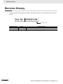
Revision History
Revision History
A manual revision code appears as a suffix to the catalog number on the front and back covers of the
manual.
Cat. No. V118-E1-02
Revision code
Revision code
01
02
26
Date
June 2014
October 2014
Revised content
Original production
Made revisions accompanying version upgrade.
NA Series Programmable Terminal Software User’s Manual (V118)
1
Introduction to the NA-series Programmable Terminals
This section describes the features, basic system configuration, specifications, and
overall operating procedure of the NA-series Programmable Terminals.
1-1 NA-series Programmable Terminals . . . . . . . . . . . . . . . . . . . . . . . . . . . . . . 1-2
1-1-1
Features . . . . . . . . . . . . . . . . . . . . . . . . . . . . . . . . . . . . . . . . . . . . . . . . . . . . . . 1-2
1-2 How HMIs Operate . . . . . . . . . . . . . . . . . . . . . . . . . . . . . . . . . . . . . . . . . . . . . 1-4
1-2-1
1-2-2
1-2-3
1-2-4
1-2-5
1-2-6
1-2-7
1-2-8
HMI Software Configuration . . . . . . . . . . . . . . . . . . . . . . . . . . . . . . . . . . . . . . .
HMI Projects . . . . . . . . . . . . . . . . . . . . . . . . . . . . . . . . . . . . . . . . . . . . . . . . . . .
Pages . . . . . . . . . . . . . . . . . . . . . . . . . . . . . . . . . . . . . . . . . . . . . . . . . . . . . . . .
Objects . . . . . . . . . . . . . . . . . . . . . . . . . . . . . . . . . . . . . . . . . . . . . . . . . . . . . . .
Memory Specifications for Connected Devices . . . . . . . . . . . . . . . . . . . . . . . .
Events . . . . . . . . . . . . . . . . . . . . . . . . . . . . . . . . . . . . . . . . . . . . . . . . . . . . . . . .
Subroutines . . . . . . . . . . . . . . . . . . . . . . . . . . . . . . . . . . . . . . . . . . . . . . . . . . . .
Functions Shared by the Entire HMI Project . . . . . . . . . . . . . . . . . . . . . . . . . . .
1-4
1-4
1-4
1-5
1-6
1-7
1-8
1-9
1-3 Operating Procedure for HMIs . . . . . . . . . . . . . . . . . . . . . . . . . . . . . . . . . . 1-10
1-3-1
1-3-2
Overall Procedure . . . . . . . . . . . . . . . . . . . . . . . . . . . . . . . . . . . . . . . . . . . . . . 1-10
Procedure Details . . . . . . . . . . . . . . . . . . . . . . . . . . . . . . . . . . . . . . . . . . . . . . .1-11
NA Series Programmable Terminal Software User’s Manual (V118)
1-1
1 Introduction to the NA-series Programmable Terminals
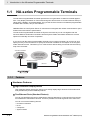
1-1
NA-series Programmable Terminals
The NA-series Programmable Terminals represent the next generation of HMIs for industrial applications. They display information on FA manufacturing sites and function as control interfaces while providing safety, reliability, and maintainability. They provide all of the functions of traditional programmable
terminals with a clearer, easy-to-use interface.
OMRON offers the new Sysmac Series of control devices designed with unified communications specifications and user interface specifications.
The NA-series Programmable Terminals are Sysmac devices that you can use together with the
NJ-series Machine Automation Controllers and the Sysmac Studio Automation Software to achieve
optimum functionality and ease of operation.
If you connect an NA-series Programmable Terminal to an NJ-series Controller, all you have to do to
specify memory in the Controller is to specify the Controller variables for the objects on the Programmable Terminal screens. This allows you to create screens without being concerned with the memory
map of the Controller.
Automation Software
NA-series PT
Sysmac Studio
Programming with
Variables to Eliminate
Worrying about the
Memory Map
Specifications with Only
Variables from Objects on
Screens
NJ-series Controller
Ethernet
1-1-1
Features
Hardware Features
High-resolution Display Panels
High-resolution display panels are used to more clearly display large amounts of information than
was possible with previous OMRON products.
Two Ethernet Ports (Standard Feature)
You can use both Ethernet ports to separate the segment attached to control devices from the segment attached to maintenance devices. Access is possible from both segments at the same time.
You can connect the following devices.
• NJ-series Controllers
• PLCs
• Computers
• Sysmac Studio
1-2
NA Series Programmable Terminal Software User’s Manual (V118)
1 Introduction to the NA-series Programmable Terminals
You can use an SD Memory Card inserted in the NA Unit to automatically transfer the project you
created on the Sysmac Studio to the NA Unit, to update the system program in the NA Unit, or to
save the log data from the NA Unit.
Software Features
1
Specifications with Variables for Superior Reusability
Program with Visual Basic
You can use Microsoft’s Visual Basic to program advanced functions that you cannot achieve with
standard objects.
A Wealth of Security Features
The many security features of the NA-series PTs include operation authority settings and execution
restrictions with IDs.
Use the Integrated Development Environment of Sysmac Studio Automation
Software
You use the Sysmac Studio to create applications for the NA-series Programmable Terminals.
The Sysmac Studio provides an integrated development environment that covers not only the
NA-series Programmable Terminal, but also the Controller and devices on EtherCAT as well.
You can use consistent procedures for all devices regardless of differences in the devices. The Sysmac Studio supports all phases of Controller application, from page creation and sequence design
through debugging, simulations, commissioning, and changes during operation.
A Wealth of Simulation Features
You can perform simulations using a virtual HMI on the Sysmac Studio. And you can also perform
online debugging with a virtual NJ-series Controller.
1-3
1-1-1 Features
If you connect to an NJ-series Controller, all you have to do to specify memory in the Controller is to
specify the Controller variables. This allows you to create objects that are not dependent on specific
devices or memory maps. This in turn makes the objects much more reusable than they were with
previous PTs.
NA Series Programmable Terminal Software User’s Manual (V118)
1-1 NA-series Programmable
Terminals
Standard-feature SD Memory Card Slot
1 Introduction to the NA-series Programmable Terminals
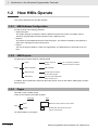
1-2
How HMIs Operate
This section describes how the HMI operates.
1-2-1
HMI Software Configuration
An HMI consists of the following software.
• System Program
The system program is required to start the HMI and execute the runtime. For details, refer to
NA-series Programmable Terminal Hardware User’s Manual (V117).
• Runtime
The runtime is the middleware that executes the project. The runtime is started by the system program and it manages execution of the project.
• Project
You use the Sysmac Studio to create your applications. The applications are executed on the runtime.
1-2-2
HMI Projects
An HMI project contains mainly the following data.
Project
Pages
Pages consist of
objects.
Global variables
HMI variables
Global events
Events that are shared
by the entire project
Subroutines
You can start subroutines
when events occur.
You can specify variables,
and the actions for events.
In addition, there is data that is shared by the entire project, such as user alarms, data logging, recipes,
and resources.
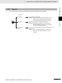
1-2-3
Pages
One HMI screen is called a page.
There are the following two types of pages.
Page type
Size
Main
Maximum screen size for each model
Popup
Smaller than the maximum screen
size for each model
Page
You paste objects on the pages.
1-4
NA Series Programmable Terminal Software User’s Manual (V118)
1 Introduction to the NA-series Programmable Terminals
1-2 How HMIs Operate
1-2-4
Objects
The objects that you paste on HMI pages consist of the following three elements.
Element
Properties
Object
These are static properties.
Example: Names and other general properties, colors,
positioning, and other display properties, and
assigned condition expressions or variables
Operating properties for condition expressions
Example: Operating specifications, such as flashing,
enabling/disabling operation, size/coordinate
changes, and displaying/hiding.
Events and
Actions
You can specify events and the actions to perform when the
events occur.
Example: You can specify subroutines to execute, e.g.,
when a function key is pressed or a value
changes.
NA Series Programmable Terminal Software User’s Manual (V118)
1-2-4 Objects
Animations
1
1-5
1 Introduction to the NA-series Programmable Terminals
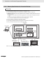
1-2-5
Memory Specifications for Connected Devices
Overview
You use HMI global variables to specify memory in a Controller or PLC.
You assign HMI global variables to connected device variables in advance to map them.
1) Variables for connected devices are registered to device variables in the HMI project with one of the
following methods.
a) Variables for connected devices that are registered in the same project are registered automatically.
b) You can copy and paste variables from another project using the clipboard.
c) You can import variables from the external connected device.
2) Devices variables are assigned to HMI global variables.
3) The assigned HMI global variables are specified in the properties of the objects.
4) Then, you transfer the project that you created to the HMI.
Sysmac Studio
project
Sysmac Studio
HMI project
Device registered in the project
(NJ-series Controller)
HMI settings
Global variables
a) Automatic registration
Global variables 3) Variables
specified in
Pages
properties
Object
1)
Device variables
b) Pasted from
clipboard.
Different project, i.e.,
in Sysmac Studio
2) Assigned.
4) Transferred.
c) Importing
HMI
Physical NJ-series
Controller or other device
Controller
Global variables
P
Refer to 4-1 Registering Variables on page 4-2 for the details on HMI variables.
1-6
NA Series Programmable Terminal Software User’s Manual (V118)
1 Introduction to the NA-series Programmable Terminals
1-2 How HMIs Operate
1-2-6
Events
Events are triggers that activate actions.*1
*1. Actions are various operations that can be directly assigned to events.
Events occur when the common page status or object status meets certain conditions.
Events are classified into three groups as shown below.
Group
Global events
Events that occur for shared project status.
Page and object events
Events that occur for specific page or object status.
User alarm events
Events that occur for user alarm status.
NA Series Programmable Terminal Software User’s Manual (V118)
1-2-6 Events
Events
1
Description
1-7
1 Introduction to the NA-series Programmable Terminals
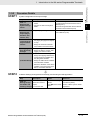
1-2-7
Subroutines
You can execute user-created subroutines in the HMI based on the following three types of conditions.
• When global events occur
• When events occur on pages or for objects
• When user alarm events occur
There are two types of subroutines that you can create.
• Global Subroutines
You create these subroutines under the global subroutine item of the HMI project.
• Page Subroutines
You create these subroutines with the page code editor.
You can use Visual Basic to write both the global subroutines and the page subroutines.
Sysmac Studio project
• Global events (i.e., events shared by all pages)
[0]: Event: F1 Key Click
Action: CallSubroutine
Events
[1]: Event: Interval
Action: IncreaseVariable
Called.
Global
subroutine
Executed.
Coded in Visual Basic
• Object event
Called. Object action
Page
subroutine
Press
Action: CallSubroutine
Page
Object
Called.
• User Alarm Event
[0]: Event: Raised
Action: CallSubroutine
[1]: Event: Acknowledged
Action: IncreaseVariable
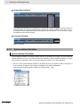
• You can call a global subroutine by executing the CallSubroutine action when a global event occurs.
1-8
NA Series Programmable Terminal Software User’s Manual (V118)
1 Introduction to the NA-series Programmable Terminals
• You can call a global subroutine by executing the CallSubroutine action when a user alarm event
occurs.
You can also call a global subroutine from another global subroutine or a page subroutine.
1-2-8
1
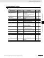
Functions Shared by the Entire HMI Project
Alarms
Alarms notify the user when certain conditions are met in the HMI.
The following alarms are supported.
• User alarms
Data Logging
You can log data to store the changes in the values of specified variables over time.
You can display the saved data with Trend Graph objects. You can also save this data to external files.
Recipes
A recipe is used to write data (numeric data or text strings) that was set in advance in the project to all
of the specified variables as a group or to read all of the specified variables as a group.
You can manipulate the registered recipe data with Recipe Viewer objects.
Resources
You can manage resources, such as the text strings, movies, still images, and documents that are displayed for objects and alarms on pages.
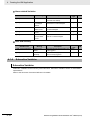
Data That Retained When Power Is Turned OFF
The following data is retained when the power supply is turned OFF.
With No Battery or Low Battery Voltage
• Project data
• Log data that is not written to the SD Memory Card
• User alarm history
• Values of variables with Retain attribute
• Calibration information for touch panel
With Good Battery (in addition to the above)
• Clock information
NA Series Programmable Terminal Software User’s Manual (V118)
1-9
1-2-8 Functions Shared by the Entire HMI Project
In addition to global events, the following functions are shared by the entire HMI project.
1-2-9
1-2 How HMIs Operate
• You can call a global subroutine or page subroutine by executing the CallSubroutine action when an
event occurs on the page or for an object.
1 Introduction to the NA-series Programmable Terminals
1-3
Operating Procedure for HMIs
This section gives the operating procedure for an HMI and then describes it in more detail.
1-3-1
Overall Procedure
The overall procedure to use an HMI is given below.
STEP1
System Configuration and Project Design
Design the system configurations and project.
STEP 1-1 Designing the System Configurations
STEP 1-2 Designing the Project (Pages, Variables, Subroutines, etc.)
STEP2
Software Settings (Configurations and Setup) and Creating the HMI Application
Create the system configurations that you designed in step 1 on the Sysmac Studio. Also create
the project (pages, variables, subroutines, etc.), build the project, and debug it with simulation
and other functions.
Determining the Connected Device Variables
and Mapping HMI Variables to Them (We recommend this as the basic procedure.)
STEP 2-1 Starting the Sysmac Studio and Creating
a Project
STEP 2-2 Software Settings (Configurations and
Setup)
STEP 2-3 Creating the HMI Application
STEP 2-4 Building the HMI
STEP 2-5 Offline Debugging
STEP3
Setting HMI Variables First and Then Mapping
Them to Connected Device Variables
STEP 2-1 Starting the Sysmac Studio and Creating
a Project
STEP 2-2 Creating the HMI Application
STEP 2-3 Software Settings (Configurations and
Setup)
STEP 2-4 Building the HMI
STEP 2-5 Offline Debugging
Mounting and Wiring
Mount the HMI.
Connect the connected device and computer (Sysmac Studio) to the HMI.
STEP4
Confirming Operation and Starting Actual System Operation
Download the project from the Sysmac Studio.
Make the settings on the System Menu, check operation on the physical devices, and start
operation.
1 - 10
NA Series Programmable Terminal Software User’s Manual (V118)
1 Introduction to the NA-series Programmable Terminals
STEP1
Procedure Details
System Configuration and Project Design
Step
STEP 1-1
Designing the
System Configurations
1) Designing the
Pages and Subroutines
2) Designing
Items Shared by
All Pages
• Connect an HMI to the Sysmac
Studio.
Design the project as given below.
Reference
Section 2 Configuration Units in NA Series
Programmable Terminal Hardware User’s
Manual (V117)
NA-series Programmable Terminal Device
Connection User’s Manual (V119)
NA Series Programmable Terminal Software
User's Manual (V118)
• Design the contents to display on
the pages (the pages and objects
to use).
• Design the execution methods
and contents of the subroutines.
• Design the global events.
• Design the alarms, recipes, data
logging, and other functions.
• HMI external variable design:
Design the mappings between the
connected device variables and
the HMI global variables.
3) Variable Design • Design the HMI internal variables
and subroutine variables.
• Define the attributes of the above
variables, such as the Data Type,
Name, and Retain attributes.
STEP2
Software Settings (Configurations and Setup) and Creating the HMI Application
Step
Description
STEP 2-1
Starting the Sysmac Studio and
Creating a Project
1. Start the Sysmac
Studio and create a
project.
2. Insert the HMI.
NA Series Programmable Terminal Software User’s Manual (V118)
Sysmac Studio operations
Press the New Project
Button.
Use HMI on the Insert
Menu.
Reference
Sysmac Studio Version 1 Operation Manual (W504)
Section 2 Basic Sysmac Studio
Operations
1 - 11
1
1-3-2 Procedure Details
STEP 1-2
Designing the
Project (Pages,
Variables, Subroutines, Etc.)
Description
• Connect an HMI to the external
device.
1-3 Operating Procedure for
HMIs
1-3-2
1 Introduction to the NA-series Programmable Terminals
Determining the Connected Device Variables and Mapping HMI Variables to
Them
We recommend this procedure as the basic procedure.
• Connecting to a Connected Device Registered in the Current Project
STEP 2-2
Software Settings (Configurations and Setup)
• Mapping Variables
• HMI Settings
• Security Settings and Language Settings
Make the initial software settings
on the Sysmac Studio.
• Assign global variables to connected device variables (mapping variables).
• Set the parameters related to
the HMI.
Startup Page, Brightness Settings, IP Address, FTP Settings,
NTP Settings, FINS Settings,
VNC Settings, etc.
• Set the operation rights to the
HMI and the language to display
on the HMI.
Use Configurations
and Setup in the Multiview Explorer of the
Sysmac Studio.
Map the variables
under Configurations and Setup −
Variable Mapping.
Make the settings
under Configurations and Setup −
HMI Settings.
Section 3 HMI Configuration and Setup
Make the settings
under Configurations and Setup −
Security Settings and
Configurations and
Setup − Language
Settings.
3-5 Security Settings
on page 3-17
3-3 Mapping Variables on page 3-7
3-4 HMI Settings on
page 3-10
3-6 Language Settings on page 3-18
• Connecting to a Connected Device Not Registered in the Current Project
STEP 2-2
Software Settings (Configurations and Setup)
Make the initial software settings
on the Sysmac Studio.
• Register the external connected
devices.
• Device Settings
1 - 12
• You can do either of the following.
a) Importing Variables from the
Actual Connected Device:
Place the Sysmac Studio
online with the connected
device and import the variables from the connected
device.
b) Importing Variables from
Another Project: Copy the
variable table in the other
project and paste it in the
variable table for the connected device to import the
variables.
Use Configurations
and Setup in the
Multiview Explorer of
the Sysmac Studio.
Add the connected
device under Configurations and Setup −
Device References.
Section 3 HMI Configuration and Setup
3-2 Device References
on page 3-3
Set up communications and import the
variables.
Copy the variable table
from another project
using the clipboard.
NA Series Programmable Terminal Software User’s Manual (V118)
1 Introduction to the NA-series Programmable Terminals
• HMI Settings
STEP 2-3
Creating the HMI
Application
1) Registering
Variables
2) Creating Pages
• Set the parameters related to
the HMI.
Startup Page, Brightness Settings, IP Address, FTP Settings,
NTP Settings, FINS Settings,
VNC Settings, etc.
• Set the operation rights to the
HMI and the language to display
on the HMI.
Create the application (pages,
variables, subroutines, etc.) with
the Sysmac Studio.
• Register the variables in the HMI
global variable table with the
Sysmac Studio.
Map the variables
under Configurations and Setup −
Variable Mapping.
Make the settings
under Configurations and Setup −
HMI Settings.
1
Make the settings
under Configurations and Setup −
Security Settings and
Configurations and
Setup − Language
Settings.
3-5 Security Settings
on page 3-17
Use HMI in the Multiview Explorer of the
Sysmac Studio.
Use the editor for HMI
− Data − Global Variables
Section 4 Creating the
HMI Application
Note: Variables that were mapped
in step 2-2 are automatically registered in the HMI global variables
table.
• Paste the objects on each page Use the editor for HMI
− Pages.
and set the object properties
and other settings.
• Create the subroutines.
You can create the following.
• Global subroutines
Section 3 HMI Configuration and Setup and
3-3 Mapping Variables on page 3-7
3-4 HMI Settings on
page 3-10
Subroutines shared by
the entire project:
Select HMI − Global
Subroutine.
Page subroutines: Use
HMI − Pages | Page
Name and select View
Code from the individual pages.
Use HMI − User
Alarms, HMI − Recipes, etc.
3-6 Language Settings on page 3-18
4-1 Registering Variables on page 4-2
4-2 Creating Pages on
page 4-11
Section 5 Objects
4-4 Subroutines on
page 4-27
3) Creating Subroutines
• Page subroutines
4) Settings
Shared by All
Pages
• Make the settings that are
shared by the project: alarms,
recipes, data logging, global
events, etc.
STEP 2-4
Building the HMI
• Convert the HMI project into a
form that the HMI can execute.
Use Build HMI on the
Project Menu.
• Check the operation of the
pages on the Simulator (a virtual
HMI).
Use Start NA Simula- Section 7 Debugging
tion or Run with Controller Simulator on
the Simulation Menu.
STEP 2-5
Offline Debugging
NA Series Programmable Terminal Software User’s Manual (V118)
4-3 Setting Common
Object Functions on
page 4-18
4-6 Building on page
4-35
1 - 13
1-3-2 Procedure Details
• Security Settings and Language Settings
Assign global variables to connected device variables (mapping
variables).
1-3 Operating Procedure for
HMIs
• Mapping Variables
1 Introduction to the NA-series Programmable Terminals
Setting HMI Variables First and Then Mapping Them to Connected Device
Variables
STEP 2-2
Creating the HMI
Application
1) Registering
Variables
2) Creating Pages
3) Creating Subroutines
4) Settings
Shared by All
Pages
Create the application (pages,
variables, subroutines, etc.)
with the Sysmac Studio.
Register the variables in the
HMI global variable table with
the Sysmac Studio.
Paste the objects on each
page and set the object properties.
Use HMI in the Multiview
Explorer of the Sysmac Studio.
HMI − Data − Global Variables
Table
Section 4 Creating the
HMI Application
Use the editor for HMI −
Pages.
4-2 Creating Pages on
page 4-11
Create the subroutines.
Subroutines shared by the
entire project: Select HMI −
Add Global Subroutine.
Page subroutines: Use HMI −
Pages and select View Code
from the individual pages.
Use HMI − User Alarms, HMI
− Recipes, etc.
You can create the following.
• Global subroutines
• Page subroutines
Make the settings that are
shared by the project: alarms,
recipes, data logging, global
events, etc.
4-1 Registering Variables on page 4-2
Section 5 Objects
4-4 Subroutines on
page 4-27
4-3 Setting Common
Object Functions on
page 4-18
• Connecting to a Connected Device Registered in the Current Project
STEP 2-3
Software Settings (Configurations and Setup)
• Mapping Variables
• HMI Settings
• Security Settings and Language Settings
1 - 14
Make the initial software settings
on the Sysmac Studio.
• Assign global variables to connected device variables (mapping variables).
• Set the parameters related to
the HMI.
Startup Page, Brightness Settings, IP Address, FTP Settings,
NTP Settings, FINS Settings,
VNC Settings, etc.
• Set the operation rights to the
HMI and the language to display
on the HMI.
Use Configurations
and Setup in the Multiview Explorer of the
Sysmac Studio.
Map the variables
under Configurations and Setup −
Variable Mapping.
Make the settings
under Configurations and Setup −
HMI Settings.
Section 3 HMI Configuration and Setup
Make the settings
under Configurations and Setup −
Security Settings and
Configurations and
Setup − Language
Settings.
3-5 Security Settings
on page 3-17
3-3 Mapping Variables on page 3-7
3-4 HMI Settings on
page 3-10
3-6 Language Settings on page 3-18
NA Series Programmable Terminal Software User’s Manual (V118)
1 Introduction to the NA-series Programmable Terminals
STEP2-3
Software Settings (Configurations and Setup)
Make the initial software settings
on the Sysmac Studio.
• Register the external connected
devices.
• HMI Settings
• Security Settings and Language Settings
STEP 2-4
Building the HMI
STEP2-5
Offline Debugging
Set up communications and import the
variables.
Section 3 HMI Configuration and Setup
3-2 Device References
on page 3-3
1
3-2-2 Connected
Devices in the Current
Project on page 3-3
Copy the variable table
from another project
using the clipboard.
Map the variables
under Configurations and Setup −
Variable Mapping.
Make the settings
under Configurations and Setup −
HMI Settings.
3-3 Mapping Variables on page 3-7
Make the settings
under Configurations and Setup −
Security Settings and
Configurations and
Setup − Language
Settings.
3-5 Security Settings
on page 3-17
• Convert the HMI project into a
form that the HMI can execute.
Use Build HMI on the
Project Menu.
4-6 Building on page
4-35
• Check the operation of the
pages on the Simulator (a virtual
HMI).
Use Start NA Simula- Section 7 Debugging
tion or Run with Controller Simulator on
the Simulation Menu.
• Set the parameters related to
the HMI.
Startup Page, Brightness Settings, IP Address, FTP Settings,
NTP Settings, FINS Settings,
VNC Settings, etc.
• Set the operation rights to the
HMI and the language to display
on the HMI.
NA Series Programmable Terminal Software User’s Manual (V118)
3-4 HMI Settings on
page 3-10
3-6 Language Settings on page 3-18
1 - 15
1-3-2 Procedure Details
• Connected
Device Settings
• You can do either of the following.
a) Importing Variables from the
Unit Connected Device:
Place the Sysmac Studio
online with the connected
device and import the variables from the connected
device.
b) Importing Variables from
Another Project: Copy the
variable table in the other
project and paste it in the
device variable table.
• Assign global variables to connected device variables (mapping variables).
Use Configurations
and Setup in the Multiview Explorer of the
Sysmac Studio.
Add the connected
device under Configurations and Setup −
Device References.
1-3 Operating Procedure for
HMIs
• Connecting to a Connected Device Not Registered in the Current Project
1 Introduction to the NA-series Programmable Terminals
STEP3
Mounting and Wiring
Step
Description
• Mount the HMI to the panel.
1) Mounting
• Wire Power Supply.
2) Wiring the
Ethernet Cable to
the Connected
Device
3) Connecting the
Computer (Sysmac Studio)
STEP4
• Wire the Ethernet cables.
• Wire the USB cable.
or
• Wire the Ethernet cable.
NA-series Programmable Terminal Device
Connection User’s Manual (V119)
2-4 Support Software in NA Series Programmable Terminal Hardware User's Manual
(V117)
Confirming Operation and Starting Actual System Operation
Step
Description
• Turn ON the power supply to the
HMI and place the Sysmac Stu1) Online Connecdio online. Then, download the
tion to Sysmac
project.*1
Studio and Proj*1.Use
the Synchronize operation
ect Download
of the Sysmac Studio to
download the project.
2) Operation
Check on NA Unit
3) Actual System
Operation
1 - 16
Reference
3-3 Installing NA Units in NA Series Programmable Terminal Hardware User's Manual (V117)
3-4 Wiring Method in NA Series Programmable Terminal Hardware User's Manual
(V117)
Sysmac Studio
operations
Use Communications Setup on the
HMI Menu.
Use Synchronization on the HMI
Menu.
• Integrate the NA Unit into the
actual system, manipulate the
project that you created and
confirm the following: that correct values are written to the
connected device, that the
pages change correctly, and that
values set at the connected
device are updated.
---
• Start actual operation.
---
Reference
Section 6 Connecting
to the HMI and Section
8 Synchronizing Projects
Section 7 Debugging
---
NA Series Programmable Terminal Software User’s Manual (V118)
2
Basic Sysmac Studio Operations
This section describes basic operations on the Sysmac Studio.
2-1 Parts of the Sysmac Studio Window . . . . . . . . . . . . . . . . . . . . . . . . . . . . . . 2-2
2-1-1
Application Window . . . . . . . . . . . . . . . . . . . . . . . . . . . . . . . . . . . . . . . . . . . . . 2-2
2-2 Menu Command Structure . . . . . . . . . . . . . . . . . . . . . . . . . . . . . . . . . . . . . . 2-6
2-3 Basic Editing Operations . . . . . . . . . . . . . . . . . . . . . . . . . . . . . . . . . . . . . . . 2-8
2-4 Sysmac Studio Settings and Operations . . . . . . . . . . . . . . . . . . . . . . . . . . 2-10
2-4-1
2-4-2
2-4-3
2-4-4
2-4-5
2-4-6
2-4-7
Setting Parameters . . . . . . . . . . . . . . . . . . . . . . . . . . . . . . . . . . . . . . . . . . . . . 2-10
Programming . . . . . . . . . . . . . . . . . . . . . . . . . . . . . . . . . . . . . . . . . . . . . . . . . 2-10
Library Functions . . . . . . . . . . . . . . . . . . . . . . . . . . . . . . . . . . . . . . . . . . . . . . .2-11
Operations for Debugging . . . . . . . . . . . . . . . . . . . . . . . . . . . . . . . . . . . . . . . . .2-11
Communications . . . . . . . . . . . . . . . . . . . . . . . . . . . . . . . . . . . . . . . . . . . . . . . .2-11
Security Measures . . . . . . . . . . . . . . . . . . . . . . . . . . . . . . . . . . . . . . . . . . . . . .2-11
Online Help . . . . . . . . . . . . . . . . . . . . . . . . . . . . . . . . . . . . . . . . . . . . . . . . . . . 2-12
2-5 Basic Operations for HMI Projects . . . . . . . . . . . . . . . . . . . . . . . . . . . . . . . 2-13
2-5-1
2-5-2
2-5-3
Creating a Project File from the Project Window . . . . . . . . . . . . . . . . . . . . . . 2-13
Adding an HMI to an Existing Project . . . . . . . . . . . . . . . . . . . . . . . . . . . . . . . 2-14
Changing Devices . . . . . . . . . . . . . . . . . . . . . . . . . . . . . . . . . . . . . . . . . . . . . . 2-15
NA Series Programmable Terminal Software User’s Manual (V118)
2-1
2 Basic Sysmac Studio Operations
2-1
Parts of the Sysmac Studio Window
This section gives the names and functions of the parts of the Sysmac Studio Window.
This manual describes only functions that apply when an HMI is selected for the device. For information
on Sysmac Studio functions not described in this manual, refer to the Sysmac Studio Version 1 Operation Manual (Cat. No. W504).
Precautions for Correct Use
When you use the Sysmac Studio, use the standard Windows desktop theme. If you do not use
the standard Windows desktop theme, part of the display may not be correct.
2-1-1
Application Window
Tab
Toolbar
Menu bar
Configurations
and Setup Header
HMI Header
(b)
(c)
(a)
Number
(a)
(b)
(c)
Name
Multiview Explorer
Edit Pane
Toolbox
The functions of these parts are described starting on the next page.
2-2
NA Series Programmable Terminal Software User’s Manual (V118)
2 Basic Sysmac Studio Operations
• This pane is your access point for all Sysmac Studio data.
When an HMI is selected, it is divided into a Configurations
and Setup Layer and an HMI Layer.
• You can also display the Page Explorer to display lists of
objects on pages or the Code Explorer to display lists of
subroutines.
2-1 Parts of the Sysmac Studio Window
Multiview Explorer (a)
2
2-1-1 Application Window
NA Series Programmable Terminal Software User’s Manual (V118)
2-3
2 Basic Sysmac Studio Operations
Layers and Items in the Multiview Explorer
Configurations and Setup
Device References
Variable Mapping
HMI Settings
Security Settings
Language Settings
HMI
Page
Pages
User Alarms
Groups
Data Logging
DataSet
Recipes
Data
Global Variables
Global Events
Global Subroutines
Subroutine Groups
Resources
IAG Resources
Precautions for Correct Use
You cannot download the data to the HMI if an error icon is displayed.
Page Explorer
The Page Explorer displays a list of objects on a page. If you click an object in the
Page Explorer, the object will be selected on the Edit Pane.
To change the attributes for grouped objects or for individual objects in IAGs, select
the individual objects on the Page Explorer.
Code Explorer
The Code Explorer displays the subroutines in the project. You can double-click a
subroutine to edit it.
Edit Pane (b)
The basic Sysmac Studio operations on the Edit Pane generally apply to HMIs. If an HMI is selected,
you can edit pages and set up the HMI.
2-4
NA Series Programmable Terminal Software User’s Manual (V118)
2 Basic Sysmac Studio Operations
• The Toolbox shows the objects that you can use to edit the page that is displayed in
the Edit Pane.
You can also display the Properties Window, Animations Window, and Events and
Actions Window to make the settings of the objects.
2-1 Parts of the Sysmac Studio Window
Toolbox (c)
2
2-1-1 Application Window
NA Series Programmable Terminal Software User’s Manual (V118)
2-5
2 Basic Sysmac Studio Operations
2-2
Menu Command Structure
The menu commands that are displayed when an HMI is selected as the device are listed below.
Menu
File
Edit
View
Insert
2-6
Submenu/command
Close
Save
Save As
Save As New Number
―
Import
Export
Exit
Undo
Redo
Cut
Copy
―
Paste
Delete
Select All
Search and Replace
Multiview Explorer
Toolbox
Output Tab Page
Watch Tab Page
Build Tab Page
―
Search and Replace Results Tab Page
Page Explorer
Code Explorer
Properties
Animations
Events and Actions
Smart Project Search
―
Recently Closed Windows
―
Clear Recently Closed Windows History
Zoom
Zoom In
Zoom Out
Zoom to Fit
Zoom Reset
Reset Window Layout
―
Controller
NJ301
NJ501
HMI
NA5
Measurement Sensor
ZW
Vision Sensor
FQ-M
FH
Slave Terminal
Ethernet/IP Coupler
External Device
Page
Page Group
―
User Alarm Group
Data Set
Recipe
Global Subroutine Group
NA Series Programmable Terminal Software User’s Manual (V118)
2 Basic Sysmac Studio Operations
HMI
Simulation
Tools
Help
Submenu/command
Build HMI
Abort Build
IAG Collections Manager
Communications Setup
Change Device
Online
Offline
Synchronization
Transfer to Media Device
HMI Clock
Update HMI Name
Security
Clear All Memory
Reset HMI Device
Start NA Simulation
Stop NA Simulation
Step Execution
Step In
Step Out
Continue
Set/Clear Breakpoint
Clear All Breakpoints
Run with Controller Simulator
Option
Help Contents
Keyboard Mapping Reference
Online Registration
About Sysmac Studio
NA Series Programmable Terminal Software User’s Manual (V118)
2-2 Menu Command Structure
Menu
Project
―
―
2
HMI Write Protection
―
―
―
―
2-7
2 Basic Sysmac Studio Operations
2-3
Basic Editing Operations
This section describes differences in basic Sysmac Studio operation when an HMI is selected as the
device.
Entry Assistance
There are some differences in the standard operation of the Sysmac Studio when an HMI is selected as
the device. This section describes those differences.
Entering Variable Names and Data Types
• Entering variable names, e.g., when setting properties
• Entering data types in variable tables
Example: When you enter a variable name as a property, the variable names that you can enter are
displayed in a list.
2-8
NA Series Programmable Terminal Software User’s Manual (V118)
2 Basic Sysmac Studio Operations
Entering Text in the Code Editor
• When you enter text in the Code Editor, the cursor moves to the first item in the list that starts with
the character that you entered.
2-3 Basic Editing Operations
• When you press the Tab Key after entering the first part of the keyword (“in” in this example), the
rest of the keyword is automatically entered.
2
NA Series Programmable Terminal Software User’s Manual (V118)
2-9
2 Basic Sysmac Studio Operations
2-4
Sysmac Studio Settings and Operations
This section lists the operations of the Sysmac Studio that can be used only when an HMI is selected.
2-4-1
Setting Parameters
Item
HMI Settings
Device References
Internal Device
External Device
Variable Mapping
2-4-2
Reference
Section 3 HMI Configuration
and Setup
If you connect an HMI to a device (e.g., Control- 3-2 Device References on
ler or PLC) that is not registered in the current
page 3-3
HMI project, the connected external device will
be added.
Controllers registered in the project are displayed.
You can set up communications and import variables for connected devices that have been
added.
You can associate variables in the connected
3-3 Mapping Variables on
devices with variables in the HMI.
page 3-7
Programming
Item
Toolbox
Properties
Animations
Events and Actions
Page Explorer
Code Explorer
Page Editor
Code Editor
2 - 10
Description
You can make settings for an HMI.
Description
The Toolbox displays a list of the objects that
you can use.
You can search for the required objects and
drag them to the Page Editor to position the
objects.
You can set the static attributes of the pages
and objects.
You can set the operations for object condition
expressions.
You can set the actions to perform when events
occur.
The Page Explorer displays a list of objects on a
page. You can select objects or change the
order of the display.
The Code Explorer displays lists of subroutines
in the project. You can double-click a subroutine
to edit it.
You can position objects and create pages. You
can also use the Page Editor to make settings
for objects.
You can use Visual Basic to create subroutines.
Reference
Section 5 Objects
4-2 Creating Pages on page
4-11
4-4 Subroutines on page 4-27
NA Series Programmable Terminal Software User’s Manual (V118)
2 Basic Sysmac Studio Operations
Build
Build HMI
Abort Build
2-4-3
IAG
Operations for Debugging
Item
Description
Reference
You can monitor variables during project execu- Section 7 Debugging
tion.
Monitoring
Changing the Present Values
of Variables
You can monitor the present values of HMI
global variables. You use the Watch Tab Page
for monitoring.
You can change the present values of global
variables and system-defined variables.
Controlling Execution with
Breakpoints and Step Execution
You can do this on a Watch Tab Page.
You can control simulation execution to monitor
the program or to check operation.
Step execution and pausing are also possible.
Section 7 Debugging
Section 7 Debugging
Communications
Item
Going Online with an HMI
2-4-6
Reference
Section 9 Reusing Objects
Description
You can place the computer online with an HMI
to synchronize the project.
Reference
Section 6 Connecting to the
HMI
Security Measures
Prevention of
Incorrect Connections
Item
Confirming HMI
device Names and
Serial IDs
Preventing Incorrect Operation
Prevention of the
Theft of Assets
Operation Authority Verification
Password Protection for Project
Files
Description
If the device name or the serial ID is different
between the project and the HMI when an
online connection is established, a confirmation
dialog box is displayed.
You can use operation authorities to restrict the
ability to perform operations or display data.
You can set password protection for project files
to protect your assets.
NA Series Programmable Terminal Software User’s Manual (V118)
2
2-4-3 Library Functions
Description
You can register objects that you have created
and then reuse them.
You can output an IAG that you created in an
IAG project as an IAG collection, to use it in
another project.
Toolbox
2-4-5
Reference
4-5 Search and Replace on
page 4-34
4-6 Building on page 4-35
Library Functions
Item
2-4-4
Description
You can search and replace strings in subroutine data.
Convert the project into a form that the HMI can
execute.
You can abort a build operation.
2-4 Sysmac Studio Settings and Operations
Item
Search and Replace
Reference
3-5 Security Settings
on page 3-17
2 - 11
2 Basic Sysmac Studio Operations
2-4-7
Online Help
Item
Sysmac Studio Help System
Description
You can access Sysmac Studio operating procedures.
Keyboard Mapping Reference You can display a list of convenient shortcut
keys that you can use on the Sysmac Studio.
2 - 12
Reference
NA Series Programmable Terminal Software User’s Manual (V118)
2 Basic Sysmac Studio Operations
Basic Operations for HMI Projects
This section describes how to create and save projects and perform other basic operations to use
HMIs.
2-5-1
Creating a Project File from the Project Window
Use the following procedure to create a project file from the Project Window.
1
2
Click the New Project Button in the Project Window.
The Project Properties Dialog Box is displayed. The following table gives the functions of the
buttons.
2
Description
Creates a project file.
Opens an existing project file.
Enter the project name, author, and comment in the Project Properties Dialog Box, select HMI
from the device category, and then click the Create Button. (Only the project name is required.)
You can change the properties later. Refer to the Sysmac Studio Version 1 Operation Manual
(Cat. No. W504).
A project file is created and the following window is displayed.
NA Series Programmable Terminal Software User’s Manual (V118)
2 - 13
2-5-1 Creating a Project File from the Project Window
Project Window
Menu command
New Project Button
Open Project Button
2-5 Basic Operations for HMI Projects
2-5
2 Basic Sysmac Studio Operations
A project file is created with the specified device already inserted.
2-5-2
Adding an HMI to an Existing Project
Right-click the Controller Icon and select Add Device from the menu.
Or, select the device directly from the Insert Menu.
Example: HMI - NA5: The Add Device Dialog Box is displayed.
Select the device and then click the OK Button. The device is added to the project.
2 - 14
NA Series Programmable Terminal Software User’s Manual (V118)
2 Basic Sysmac Studio Operations
2-5-3
Changing Devices
Right-click the HMI Icon and select Change Device from the menu. Or, select Change Device from the
HMI Menu.
2-5 Basic Operations for HMI Projects
To change the target device, select a device from the list.
2
The Change Device Dialog Box is displayed.
2-5-3 Changing Devices
Select the device and then click the OK Button. The device is changed.
Precautions for Correct Use
• If you change the device, the settings for functions that are not supported by the new model
will be lost.
• If you change to a model that has a different display size, the objects will be enlarged or
reduced according to the new display size. However, elements other than objects, such as
font sizes, will not change.
HMI Versions
Set the version when you create a new HMI project or when you add an HMI to an existing project.
You can set the version to the runtime version of the HMI that you are using. You can program and
make settings within the ranges that are supported for the runtime version. If you attempt to use functions that are not supported by the runtime version that you set, you will not be able to use them or
errors will occur.
Additional Information
Sysmac Studio version 1.10 is required to use HMI version 1.00. If you open a project that was
created for HMI version 1.00 on Sysmac Studio version 1.11 or higher, the HMI version will be
changed to version 1.01.
NA Series Programmable Terminal Software User’s Manual (V118)
2 - 15
2 Basic Sysmac Studio Operations
2 - 16
NA Series Programmable Terminal Software User’s Manual (V118)
HMI Configuration and Setup
3
This section describes how to configure and set up HMIs on the Sysmac Studio, including mapping variables with connected devices and HMI settings.
3-1 Outline of Configurations and Setup . . . . . . . . . . . . . . . . . . . . . . . . . . . . . . 3-2
3-1-1
Connected Device Registration and Variable Mapping . . . . . . . . . . . . . . . . . . . 3-2
3-2 Device References . . . . . . . . . . . . . . . . . . . . . . . . . . . . . . . . . . . . . . . . . . . . . 3-3
3-2-1
3-2-2
3-2-3
Types of Connected Devices . . . . . . . . . . . . . . . . . . . . . . . . . . . . . . . . . . . . . . 3-3
Connected Devices in the Current Project . . . . . . . . . . . . . . . . . . . . . . . . . . . . 3-3
Registering External Connected Devices . . . . . . . . . . . . . . . . . . . . . . . . . . . . . 3-4
3-3 Mapping Variables . . . . . . . . . . . . . . . . . . . . . . . . . . . . . . . . . . . . . . . . . . . . . 3-7
3-3-1
3-3-2
3-3-3
Mapping Variables . . . . . . . . . . . . . . . . . . . . . . . . . . . . . . . . . . . . . . . . . . . . . . 3-7
Opening the Variable Mapping Tab Page and Tab Page Parts . . . . . . . . . . . . . 3-7
Variable Mapping Methods . . . . . . . . . . . . . . . . . . . . . . . . . . . . . . . . . . . . . . . . 3-8
3-4 HMI Settings . . . . . . . . . . . . . . . . . . . . . . . . . . . . . . . . . . . . . . . . . . . . . . . . . 3-10
3-4-1
3-4-2
3-4-3
3-4-4
3-4-5
3-4-6
3-4-7
HMI Settings . . . . . . . . . . . . . . . . . . . . . . . . . . . . . . . . . . . . . . . . . . . . . . . . . . 3-10
Device Settings . . . . . . . . . . . . . . . . . . . . . . . . . . . . . . . . . . . . . . . . . . . . . . . . .3-11
TCP/IP Settings . . . . . . . . . . . . . . . . . . . . . . . . . . . . . . . . . . . . . . . . . . . . . . . 3-12
FTP Settings . . . . . . . . . . . . . . . . . . . . . . . . . . . . . . . . . . . . . . . . . . . . . . . . . . 3-13
NTP Settings . . . . . . . . . . . . . . . . . . . . . . . . . . . . . . . . . . . . . . . . . . . . . . . . . . 3-14
FINS Settings . . . . . . . . . . . . . . . . . . . . . . . . . . . . . . . . . . . . . . . . . . . . . . . . . 3-15
VNC Settings . . . . . . . . . . . . . . . . . . . . . . . . . . . . . . . . . . . . . . . . . . . . . . . . . 3-16
3-5 Security Settings . . . . . . . . . . . . . . . . . . . . . . . . . . . . . . . . . . . . . . . . . . . . . 3-17
3-6 Language Settings . . . . . . . . . . . . . . . . . . . . . . . . . . . . . . . . . . . . . . . . . . . . 3-18
3-7 HMI Clock . . . . . . . . . . . . . . . . . . . . . . . . . . . . . . . . . . . . . . . . . . . . . . . . . . . 3-19
3-8 Updating the HMI Name . . . . . . . . . . . . . . . . . . . . . . . . . . . . . . . . . . . . . . . . 3-20
3-9 Write Protecting the HMI . . . . . . . . . . . . . . . . . . . . . . . . . . . . . . . . . . . . . . . 3-21
3-10 Clear All Memory . . . . . . . . . . . . . . . . . . . . . . . . . . . . . . . . . . . . . . . . . . . . . 3-22
3-11 Resetting the HMI . . . . . . . . . . . . . . . . . . . . . . . . . . . . . . . . . . . . . . . . . . . . . 3-23
NA Series Programmable Terminal Software User’s Manual (V118)
3-1
3 HMI Configuration and Setup
3-1
Outline of Configurations and Setup
This section describes how to set up HMIs and connected devices, such as Controllers and PLCs. The
following items are provided in the HMI Configurations and Setup.
Item
Description
Device References
You can set up connected devices and import variables.
Variable Mapping
HMI Settings
Security Settings
Language Settings
You can assign HMI variables to the variables in the connected devices.
These are the parameters related to the HMI.
You can set up restrictions to operations on HMIs.
You can make settings for multi-language projects.
3-1-1
Connected Device Registration and Variable Mapping
Device references must be set only to connect to external devices that are not registered in the current
project. They are not necessary to connect to a Controller that is registered in the current project.
The following figure shows the relationship between connected device references and variable mapping.
The HMI global variables are mapped to the connected device variables.
To access variables in the connected devices from an HMI, you must map the variables.
Sysmac Studio Project
Pages
Page 1
Page 0
Object Properties
Object
Behaviour
Expression Controller0_aaa
(E) Selectable
HMI Global Variable Table
Variable name Data type
Boolean
Integer
■ Connected Device References
Global variables of connected devices
■ Variable Map
(C)Mapping
Position Port Data type Variable name
Controller0 aaa Boolean
bbb Integer
(D) Automatic registration
Selectable
(A)
(B)
(C)
(D)
(E)
3-2
Variable name Data type
Boolean
aaa
bbb
Integer
External device
Variables copied through the clipboard from other
projects or variables imported by accessing the
physical device (PLC or Controller)
Importing connected
device variables
(B) Automatic registration
Variables automatically imported from Controllers in the project
Internal
device
Connected device variables are a) automatically imported from the same project or b) copied from
another project or manually imported from an external device.
The connected device variables are automatically registered in the variable mappings.
The HMI global variables are mapped to the connected device variables.
The mapped HMI global variables are automatically registered in the global variable table of the HMI.
You specify HMI global variables in the object properties.
NA Series Programmable Terminal Software User’s Manual (V118)
3 HMI Configuration and Setup
3-2
Device References
This section describes how to set up HMIs and connected devices, such as Controllers and PLCs.
Types of Connected Devices
Different operations are used to connect to Controllers that are registered and Controllers that are not
registered in the current project.
• Controllers that are already registered in the current project are automatically registered in the HMI
project as internal connected devices.
• To connect to a device that is not registered in the current HMI project, you must register the device
as an external connected device.
3-2 Device References
3-2-1
3
Additional Information
3-2-2
Connected Devices in the Current Project
Controllers that are registered in the current project are displayed as connected devices. Use the following procedure to display the device settings if you need to check them.
1
2
3
Click Device References under Configurations and Setup in the Multiview Explorer.
The Controllers that are registered in the current project are displayed under Internal Device.
Double-click the project to display the following Device Configuration Tab Page.
NA Series Programmable Terminal Software User’s Manual (V118)
3-3
3-2-1 Types of Connected Devices
If you upload a project that includes Controllers registered as internal connected devices to a
project in which the Controllers are not registered, the devices are registered as internal connected devices that do not have links to Controllers. Refer to 8-1 Synchronizing Projects on
page 8-2 for details.
3 HMI Configuration and Setup
3-2-3
Registering External Connected Devices
To connect the HMI to a device that is not registered in the current HMI project, you must register the
device as an external connected device. The procedures to register and set up external connected
devices are given below.
Registering and Setting Up External Connected Devices
This section describes how to register and set up external connected devices.
1
2
3
3-4
Right-click Device References under Configurations and Setup in the Multiview Explorer.
Select Add - ExternalDevice. The device is added as ExternalDevice, where is a serial
number starting from 0.
Double-click the new ExternalDevice.
NA Series Programmable Terminal Software User’s Manual (V118)
3 HMI Configuration and Setup
4
Select the vendor of the required device in the Device Vendor Box under Device Configuration. The device series of the selected vendor is displayed. Make the selections for the required
device. The device communications drivers of the vendor selected for the device series are displayed. Select the communications driver for the required device.
3-2 Device References
5
Make the required settings in the Communications Configuration Area. Refer to the NA-series
Programmable Terminal Device Connection User’s Manual (Cat. No. V119) for details.
3
3-2-3 Registering External Connected Devices
NA Series Programmable Terminal Software User’s Manual (V118)
3-5
3 HMI Configuration and Setup
Importing External Connected Device Variables
To connect the HMI to a device that is not registered in the current HMI project, you must import the
variables from the external connected device.
There are two ways to import external connected device variables.
• Importing device variables online from the actual external connected device
• Copying variables from the variable table in another project
Importing Device Variables Online from the Actual External Connected
Device
Click the Import Variables Button. The variables are imported from the external connected device.
Refer to the NA-series Programmable Terminal Device Connection User’s Manual (Cat. No. V119)
for details.
Copying Variables from the Variable Table in Another Project
You can use the clipboard to copy the required variables from the Support Software for the connected device and paste them in the device variables table for the external connected device. However, you cannot copy connected device variables if they are structure variables.
Refer to the NA-series Programmable Terminal Device Connection User’s Manual (Cat. No. V119)
for details.
Updating Device Variables
If you change the variables on a device, update the device variables in the HMI project as required.
There are two ways to update device variables.
• Updating device variables online from the actual external connected device
• Copying variables from the variable table in another project
Updating Device Variables Online from the Actual External Connected Device
Click the Update Variables Button. The differences between the variables on the external connected device and the device variables in the HMI project are displayed. Select the variables to
update.
Copying Variables from the Variable Table in Another Project
You can use the clipboard to copy the required variables from the Support Software for the connected device and paste them in the device variables table for the external connected device.
3-6
NA Series Programmable Terminal Software User’s Manual (V118)
3 HMI Configuration and Setup
3-3
Mapping Variables
This section describes the settings required to access variables in connected devices through HMI
global variables.
Mapping Variables
Mapping variables refers to assigning variables in devices connected to the HMI (called device variables) to global variables in the HMI. Device variables are used on the HMI by assigning them to HMI
global variables.
Therefore, mapping variables is required. Not accessing device variables directly allows you to reuse
projects simply by changing the variable mappings.
3-3 Mapping Variables
3-3-1
3
Global variables that are assigned to device variables are called external variables.
3-3-1 Mapping Variables
3-3-2
Opening the Variable Mapping Tab Page and Tab Page Parts
1
Double-click Variable Mapping under Configurations and Setup.
The Variable Mapping Tab Page is displayed.
Parts of the Window
No
1
2
3
Item
Position
Port
Data Type
Description
Displays the IP addresses of the connected devices.
Displays the connected devices and device variables in a tree structure.
The data types of the device variables are displayed.
NA Series Programmable Terminal Software User’s Manual (V118)
3-7
3 HMI Configuration and Setup
3-3-3
No
4
Item
Variable
5
Variable Comment
Description
You can set the name of a HMI global variable. You can use entry assistance to
select from a list of previously registered HMI global variables.
You can set comments for the HMI global variables. These comments are also
applied to the global variable table.
Variable Mapping Methods
To map variables, you can either create new global variables and assign them or you can assign previously created global variables.
To increase the reusability of the project, create the global variables first and then assign them.
However, if a device variable is a structure, you must create a new external variable during variable
mapping.
Creating New External Variables
You can create a new global variable and assign it to a device variable.
When you create an external variable, you can either have the name generated automatically or you
can create it manually.
Automatically Creating New Variable Names
Use the following procedure.
1
Select one or more device variables in the variable mappings, right-click, and select Create
Device Variable from the popup menu.
Automatically generated variable names are registered in the global variable table according to
the following rule.
Automatic generation rule: The device variable name is added after the controller name and
separated with an underline.
Manually Entering New Variable Names
Select the device variable and directly enter the variable name in the Variable column.
3-8
NA Series Programmable Terminal Software User’s Manual (V118)
3 HMI Configuration and Setup
Selecting Previously Registered Global Variables and Mapping
Them
You can select global variables that are already registered in the global variable table and assign them
to device variables.
3-3 Mapping Variables
For example, this method can be used to map external variables in the following cases.
• Setting an HMI global variable first and then assigning it to a device variable
• Creating a common project first and specifying connected devices later
Use the following procedure.
1
2
Register the global variables in the global variable table in advance.
When you map variables, you can select global variables from lists of variables that are already
registered in the global variable table and assign them to device variables.
3
3-3-3 Variable Mapping Methods
NA Series Programmable Terminal Software User’s Manual (V118)
3-9
3 HMI Configuration and Setup
3-4
HMI Settings
This section describes the HMI settings.
3-4-1
HMI Settings
You can make settings for an HMI.
The following table lists the setting items.
Item
Device Settings
Description
There are page, screen saver,
brightness settings, and other settings.
These are the Ethernet settings for
Ethernet ports 1 and 2.
When setting is required
These settings are always required.
FTP Settings
These are the FTP server settings.
These settings are required to use
the FTP server.
NTP Settings
These are the NTP client settings.
These settings are required when
you use an NTP client.
FINS Settings
These are the settings for FINS com- These settings are required when
munications.
using FINS communications with a
CJ-series PLC.
These are the VNC settings.
These settings are required to use
VNC.
TCP/IP Settings
VNC Settings
Icon
These settings are always required.
Setting Procedure for HMI Settings
1
2
3 - 10
Double-click HMI Settings under Configurations and Setup in the Multiview Explorer. The
HMI Settings Tab Page is displayed in the Edit Pane.
Click the icons on the left to display the corresponding dialog boxes.
NA Series Programmable Terminal Software User’s Manual (V118)
3 HMI Configuration and Setup
3-4-2
Device Settings
These are the device settings.
3-4 HMI Settings
3
3-4-2 Device Settings
Item
Startup Page
Page name
Startup Language
Startup language
USB Keyboard
Key layout
Security
Automatically log out user
after period of inactivity.
Inactivity period
Screen Saver
Screen saver type
Active after
Screen Brightness
Screen brightness
System Menu
Double-tap Interval
Detectable corner
Description
Sets the page to display first when the HMI is started.
Sets the project language to use when the HMI is started.
Sets the layout of a USB keyboard.
Select this check box to automatically log out the user after a specified
period of inactivity.
Specify the time of inactivity before the user is logged out automatically.
Sets the type of screen saver.
Sets the time after the screen is touched before the screen saver is started.
Sets the brightness of the screen.
Sets the interval to use to detect double taps.
Select the corners in which to detect the operation to display the System
Menu.
NA Series Programmable Terminal Software User’s Manual (V118)
3 - 11
3 HMI Configuration and Setup
3-4-3
TCP/IP Settings
These are the settings for TCP/IP.
The following settings are provided for Ethernet port 1 and Ethernet port 2.
Item
Ethernet Port 1 - Settings
IP Address
Subnet mask
Default gateway
Primary DNS server
Secondary DNS server
Primary WINS server
Secondary WINS server
Ethernet Port 2 - Settings
Direct connection with Sysmac Studio
IP Address
Subnet mask
Default gateway
Primary DNS server
Secondary DNS server
Primary WINS server
Secondary WINS server
3 - 12
Description
Sets the local IP address.
Sets the subnet mask.
Sets the IP address of the default gateway. This setting is not required when
a default gateway is not used.
Sets the IP address of the primary DNS server.
Sets the IP address of the secondary DNS server.
Sets the IP address of the primary WINS server.
Sets the IP address of the secondary WINS server.
Select this check box to connect Ethernet port 2 directly to the Sysmac Studio without going through an Ethernet switch. If you select this check box,
the IP addresses and other settings for Ethernet port 2 are ignored.
Sets the local IP address.
Sets the subnet mask.
Sets the IP address of the default gateway. This setting is not required when
a default gateway is not used.
Sets the IP address of the primary DNS server.
Sets the IP address of the secondary DNS server.
Sets the IP address of the primary WINS server.
Sets the IP address of the secondary WINS server.
NA Series Programmable Terminal Software User’s Manual (V118)
3 HMI Configuration and Setup
3-4-4
FTP Settings
These are the FTP server settings.
3-4 HMI Settings
3
3-4-4 FTP Settings
Item
FTP Settings
FTP server
Login name
Password
Description
Specifies whether to use the FTP server of the HMI.
Sets the login name to externally connect to Ethernet port 1 or 2 on the HMI
via FTP. You can use up to 12 alphanumeric characters.
Sets the password to use to externally connect to Ethernet port 1 or 2 via FTP.
You can use 8 to 32 alphanumeric characters.
NA Series Programmable Terminal Software User’s Manual (V118)
3 - 13
3 HMI Configuration and Setup
3-4-5
NTP Settings
These are the settings for an NTP (Network Time Protocol) client.
The HMI gets the clock information from the specified NTP server at the specified interval and updates
the built-in clock information.
Item
NTP Settings
Synchronize with an Internet
time server
NTP server
Interval
3 - 14
Description
Select this check box to synchronize the built-in clock in the HMI with the
clock information from the NTP server.
Sets the IP address of the NTP server.
Sets the interval at which to get the clock information from the NTP server.
NA Series Programmable Terminal Software User’s Manual (V118)
3 HMI Configuration and Setup
3-4-6
FINS Settings
These are the settings for FINS communications.
These settings are required when FINS communications are used between the HMI and a CJ-series
PLC.
3-4 HMI Settings
3
3-4-6 FINS Settings
Item
FINS Address
Ethernet port #1
Ethernet port #2
Description
Sets the FINS network address of Ethernet port 1.
The FINS node address is automatically created from the IP address.
Sets the FINS network address of Ethernet port 2.
The FINS node address is automatically created from the IP address.
FINS/UDP
FINS/UDP port no
Remote Network Table
Displays the port number used for FINS/UDP.
Sets the routing table.
NA Series Programmable Terminal Software User’s Manual (V118)
3 - 15
3 HMI Configuration and Setup
3-4-7
VNC Settings
These are the settings for VNC (Virtual Network Computing).
VNC implements a remote desktop to allow remote control of a computer located on a network.
You must enable the server functionality on the HMI to control. You can start the client software on the
computer from which to perform remote control, connect to the HMI, and then control it remotely.
Item
VNC Settings
Enable VNC
Port No.
Mode
Password
3 - 16
Description
Specifies whether to use VNC.
Sets the port number.
Sets the operations to enable from the VNC client.
Sets the password.
NA Series Programmable Terminal Software User’s Manual (V118)
3 HMI Configuration and Setup
3-5
Security Settings
These settings are used to restrict the operations that can be performed on the HMI and register
accounts.
3-5 Security Settings
Setting Procedure for Security Settings
1
Double-click Security under Configurations and Setup in the Multiview Explorer.
The Security Settings Tab Page is displayed in the Edit Pane.
3
Item
User Accounts
Roles and Access Levels
Security Settings
Description
Registers user accounts.
Sets the access level for each role.
Sets the level of operations to permit from the System Menu.
NA Series Programmable Terminal Software User’s Manual (V118)
3 - 17
3 HMI Configuration and Setup
3-6
Language Settings
These settings are used for multi-language projects.
Project Language and System Language
There are two languages on the HMI.
• Project Language
The project language is displayed for the project that you create.
• System Language
The system language is displayed for the System Menu and for error messages displayed by the system.
The two language settings are managed as pairs. If you change the project language, the paired system language will also change.
Language Setting Procedure
1
Double-click Language Settings under Configurations and Setup in the Multiview Explorer.
The Language Settings Tab Page is displayed in the Edit Pane.
Item
Default language
Other languages
Description
Sets the language that is displayed by default.
Sets the languages to add in addition to the default languages.
Additional Information
You can clear the selection of the Transfer to Device Check Box so that the language files are
not transferred to the HMI. You can use this to delete unnecessary languages depending on the
destination of the HMI.
3 - 18
NA Series Programmable Terminal Software User’s Manual (V118)
3 HMI Configuration and Setup
3-7
HMI Clock
To set the clock in the HMI, select HMI Clock from the HMI Menu when you are online. Set the required
items and click the Apply Button to update the information in the HMI.
3-7 HMI Clock
3
Item
Time Zone
Computer
HMI
Automatically adjust clock for
DST
Date and time
Computer
Synchronize with computer
HMI
Description
Displays the time zone of the computer.
Sets the time zone of the HMI
Select this check box to enable automatically adjusting for daylight savings
time.
Displays the current date and time on the computer.
Updates the clock information on the HMI with the clock information from the
computer.
Set the clock information on the HMI.
NA Series Programmable Terminal Software User’s Manual (V118)
3 - 19
3 HMI Configuration and Setup
3-8
Updating the HMI Name
To change the HMI name, select HMI Name from the HMI Menu when you are online.
A confirmation dialog box is displayed. To update the HMI name that is set in the project, click the Yes
Button.
3 - 20
NA Series Programmable Terminal Software User’s Manual (V118)
3 HMI Configuration and Setup
3-9
Write Protecting the HMI
A confirmation dialog box is displayed. Click the Yes Button to write-protect the HMI.
3
Only the project is write-protected. The project can still log data and write other data.
NA Series Programmable Terminal Software User’s Manual (V118)
3-9 Write Protecting the HMI
To write-protect the HMI, select Security - HMI Write Protection from the HMI Menu when you are
online.
3 - 21
3 HMI Configuration and Setup
3-10 Clear All Memory
You can initialize the HMI.
When you perform the Clear All Memory operation, all data is cleared except for time data. To clear all
memory in the HMI, select Clear All Memory from the HMI Menu when you are online.
A confirmation dialog box is displayed. Click the OK Button to clear all memory.
3 - 22
NA Series Programmable Terminal Software User’s Manual (V118)
3 HMI Configuration and Setup
3-11 Resetting the HMI
You can reset the HMI.
3-11 Resetting the HMI
To reset the HMI, select Reset HMI Device from the HMI Menu when you are online. A confirmation
dialog box is displayed. Click the Yes Button to reset the HMI.
3
NA Series Programmable Terminal Software User’s Manual (V118)
3 - 23
3 HMI Configuration and Setup
3 - 24
NA Series Programmable Terminal Software User’s Manual (V118)
Creating the HMI Application
This section describes how to create the HMI application (pages, variables, subroutines, etc.) with the Sysmac Studio.
4-1 Registering Variables . . . . . . . . . . . . . . . . . . . . . . . . . . . . . . . . . . . . . . . . . . . 4-2
4-1-1
4-1-2
4-1-3
4-1-4
4-1-5
4-1-6
Variables . . . . . . . . . . . . . . . . . . . . . . . . . . . . . . . . . . . . . . . . . . . . . . . . . . . . . . 4-2
Registering Global Variables . . . . . . . . . . . . . . . . . . . . . . . . . . . . . . . . . . . . . . . 4-2
Registering External Variables . . . . . . . . . . . . . . . . . . . . . . . . . . . . . . . . . . . . . 4-4
Attributes and Entry Methods for Global Variables . . . . . . . . . . . . . . . . . . . . . . 4-5
System-defined Variables . . . . . . . . . . . . . . . . . . . . . . . . . . . . . . . . . . . . . . . . . 4-8
Subroutine Variables . . . . . . . . . . . . . . . . . . . . . . . . . . . . . . . . . . . . . . . . . . . . 4-10
4-2 Creating Pages . . . . . . . . . . . . . . . . . . . . . . . . . . . . . . . . . . . . . . . . . . . . . . . 4-11
4-2-1
4-2-2
4-2-3
4-2-4
Displaying Pages . . . . . . . . . . . . . . . . . . . . . . . . . . . . . . . . . . . . . . . . . . . . . .
Registering Pages . . . . . . . . . . . . . . . . . . . . . . . . . . . . . . . . . . . . . . . . . . . . .
Page Property Settings . . . . . . . . . . . . . . . . . . . . . . . . . . . . . . . . . . . . . . . . . .
Editing Pages . . . . . . . . . . . . . . . . . . . . . . . . . . . . . . . . . . . . . . . . . . . . . . . . .
4-12
4-12
4-14
4-15
4-3 Setting Common Object Functions . . . . . . . . . . . . . . . . . . . . . . . . . . . . . . 4-18
4-3-1
4-3-2
4-3-3
4-3-4
4-3-5
4-3-6
4-3-7
Registering User Alarms . . . . . . . . . . . . . . . . . . . . . . . . . . . . . . . . . . . . . . . . .
Registration for Data Logging . . . . . . . . . . . . . . . . . . . . . . . . . . . . . . . . . . . . .
Registering Recipes . . . . . . . . . . . . . . . . . . . . . . . . . . . . . . . . . . . . . . . . . . . .
Setting Global Events and Corresponding Actions . . . . . . . . . . . . . . . . . . . . .
Registering Global Subroutines . . . . . . . . . . . . . . . . . . . . . . . . . . . . . . . . . . .
Setting Up Resources . . . . . . . . . . . . . . . . . . . . . . . . . . . . . . . . . . . . . . . . . . .
Setting Up IAG Resources . . . . . . . . . . . . . . . . . . . . . . . . . . . . . . . . . . . . . . .
4-18
4-20
4-21
4-22
4-24
4-25
4-26
4-4 Subroutines . . . . . . . . . . . . . . . . . . . . . . . . . . . . . . . . . . . . . . . . . . . . . . . . . 4-27
4-4-1
4-4-2
4-4-3
4-4-4
Subroutine Execution . . . . . . . . . . . . . . . . . . . . . . . . . . . . . . . . . . . . . . . . . . .
Precautions on Internal Processing . . . . . . . . . . . . . . . . . . . . . . . . . . . . . . . .
Code Editor . . . . . . . . . . . . . . . . . . . . . . . . . . . . . . . . . . . . . . . . . . . . . . . . . . .
Differences in Language Specifications . . . . . . . . . . . . . . . . . . . . . . . . . . . . .
4-28
4-32
4-32
4-33
4-5 Search and Replace . . . . . . . . . . . . . . . . . . . . . . . . . . . . . . . . . . . . . . . . . . . 4-34
4-6 Building . . . . . . . . . . . . . . . . . . . . . . . . . . . . . . . . . . . . . . . . . . . . . . . . . . . . . 4-35
4-6-1
4-6-2
Building . . . . . . . . . . . . . . . . . . . . . . . . . . . . . . . . . . . . . . . . . . . . . . . . . . . . . . 4-35
Build Operation . . . . . . . . . . . . . . . . . . . . . . . . . . . . . . . . . . . . . . . . . . . . . . . . 4-35
4-7 Offline Comparison . . . . . . . . . . . . . . . . . . . . . . . . . . . . . . . . . . . . . . . . . . . 4-36
NA Series Programmable Terminal Software User’s Manual (V118)
4-1
4
4 Creating the HMI Application
4-1
4-1-1
Registering Variables
Variables
A variable is a ‘container’ that holds data.
The HMI supports the following types of variables.
Variable type
Global variables
Description
Global variables are defined by the user and can be accessed from anywhere in the
project. You can register up to 35,000 total in the entire project and up to 20,000 for
each connected device.
Global variables are declared in the HMI global variable table.
External variables
Internal variables
System-defined
variables
Subroutine variables
Global variables include external variables and internal variables, which are
described below.
External variables are global variables that are used to access data in Controllers
and other connected devices.
External variables are assigned to device variables in the variable mapping.
An internal variable can be used only within the HMI.
All global variables that are not external variables are internal variables.
System-defined variables are provided in advance in the HMI. The names and all
attributes are defined by the system. They have specific functions.
You cannot change the variable names or any other attributes of these variables.
Subroutine variables are defined by the user and are used only within subroutines.
Subroutine variables are declared in Dim statements in page subroutines or global
subroutines.
You can use all of the data types that are supported by Visual Basic.
4-1-2
Registering Global Variables
Opening the Global Variable Tab Page
Double-click Global Variables under HMI - Data in the Multiview Explorer. Or, right-click Global
Variables under HMI - Data and select Edit from the menu.
4-2
NA Series Programmable Terminal Software User’s Manual (V118)
4 Creating the HMI Application
The global variable table is displayed in the Edit Pane.
4-1 Registering Variables
4
However, the following items are different. Refer to 4-1-4 Attributes and Entry Methods for Global
Variables on page 4-5.
Item
Name
Data Type
AT
Update Rate
Description
There are specific prohibited characters that apply to HMIs.
There are specific data types for HMIs.
You can set the device variables to which to assign the global variables. This setting is
not used for internal variables.
You can select the interval at which to get values from the connected device. This setting is used only for external variables.
Additional Information
Even if you change the name of a previously registered global variable, the name of the variable accessed from objects or subroutines will not change.
NA Series Programmable Terminal Software User’s Manual (V118)
4-3
4-1-2 Registering Global Variables
The basic Sysmac Studio operations for the global variable table generally apply to HMIs. Refer to
the Sysmac Studio Version 1 Operation Manual (Cat. No. W504) for the basic operations.
4 Creating the HMI Application
4-1-3
Registering External Variables
External Variables
External variables are global variables that are used to access data in connected devices.
Creating External Variables
External variables are created in the variable mapping.
The global variables are mapped to the connected device variables.
In the variable mapping, you can create new variables or you can select variables that were previously
created.
If you create a new external variable in the variable mapping, it will automatically be registered as a
global variable.
Refer to 3-3 Mapping Variables on page 3-7 for details on the variable mapping.
Attributes of External Variables
If you create a new external variable in the variable mapping, the following attributes are registered for
it in the global variable table.
Refer to 4-1-5 System-defined Variables on page 4-8 for details on the attributes of variables.
Attribute
Name
Data Type
Initial Value
AT
Retain
Constant
Update Rate
Comment
4-4
Setting
Specified variable name
Refer to the NA-series Programmable Terminal Device Connection
User’s Manual (Cat. No. V119) for details on data type for the HMI
global variables based on data types for device variable.
None
Device_name.Device_variable_name
Non-retained
None
500 ms
Specified comment
Changes to settings
Possible.
Possible.
Not possible.
Possible.
Not possible.
Not possible.
Possible.
Possible.
NA Series Programmable Terminal Software User’s Manual (V118)
4 Creating the HMI Application
4-1-4
Attributes and Entry Methods for Global Variables
This section describes attributes and entry methods for global variables.
Attributes of Global Variables
Name Attribute
4-1 Registering Variables
Enter a text string for the name. Observe the following restrictions.
• You cannot use any symbols except for underscores.
• The first letter cannot be a number.
• The names are not case sensitive.
• You cannot use names that start with “_HMI”.
4
• You cannot use names that are reserved for the Sysmac Studio or Visual Basic.
• You cannot use more than 127 characters.
4-1-4 Attributes and Entry Methods for Global Variables
• You cannot use three underscores in a row.
NA Series Programmable Terminal Software User’s Manual (V118)
4-5
4 Creating the HMI Application
Data Type Attribute
Enter a data type directly or select one from the list.
You can use the following data types, which are supported by Visual Basic. Arrays of the data types that
are supported by Visual Basic are also supported. If you specify an array, specify the element number
in parentheses after the data type in the same way as in Visual Basic.
Classification
Basic data
types
Derivative
data types
Boolean
Byte
Char
Date
Data type
name
Boolean
Byte
Char
Date
―
1 byte
2 bytes
8 bytes
Decimal
Decimal
16 bytes
Double
Double
8 bytes
Data type
Size
Integer
Long
Integer
Long
4 bytes
8 bytes
SByte
Short
Single
SByte
Short
Single
1 byte
2 bytes
4 bytes
String
String
UInteger
ulong
UInteger
ULong
ushort
TimeSpan
Structures
Unions
Enumerations
Variable
length
4 bytes
8 bytes
Range of values
True or False
0 to 255 (unsigned)
0 to 65,535 (unsigned)
0:00:00 (midnight) on January 1, 0001 through
11:59:59 PM on December 31, 9999
0 through
+/-79,228,162,514,264,337,593,543,950,335
(+/-7.9...E+28) with no decimal point;
0 through +/-7.9228162514264337593543950335
with 28 places to the right of the decimal;
smallest nonzero number is
+/-0.0000000000000000000000000001 (+/-1E-28)
-1.79769313486231570E+308 through
-4.94065645841246544E-324 for negative values;
4.94065645841246544E-324 through
1.79769313486231570E+308 for positive values
-2,147,483,648 through 2,147,483,647 (signed)
-9,223,372,036,854,775,808 through
9,223,372,036,854,775,807 (9.2...E+18) (signed)
-128 through 127 (signed)
-32,768 through 32,767 (signed)
-3.4028235E+38 through -1.401298E-45 for negative
values;
1.401298E-45 through 3.4028235E+38 for positive
values
0 to approximately 2 billion Unicode characters
0 through 4,294,967,295 (unsigned)
0 through 18,446,744,073,709,551,615 (1.8...E+19)
(unsigned)
UShort
2 bytes
0 to 65,535 (unsigned)
Structure that gives a time interval
To use structures as global variables, you must import them from a connected
device. You can use subroutine variables if you declare them inside the subroutine.
Unions are not supported.
Enumerations are supported only in subroutines.
Refer to the NA-series Programmable Terminal Device Connection User’s Manual (Cat. No. V119) for
information on which of the above HMI variable data types can be assigned to the data types of connected device variables for different connected devices.
4-6
NA Series Programmable Terminal Software User’s Manual (V118)
4 Creating the HMI Application
Initial Value Attribute
Specify a value for the variable for one of the following situations when the Retain attribute is not
specified.
• When the power supply is turned ON
• When you specify to initialize the value when the project is transferred
Select None for no initial value. You cannot specify the Initial Value attribute for an external variable.
AT Attribute
4-1 Registering Variables
Enter a value directly or select an item from the list (the values in the list depend on the data type). If
you do not enter an initial value, 0 is used as the initial value.
4
This attribute is specified for external variables. Use the following format.
4-1-4 Attributes and Entry Methods for Global Variables
Device_name.Device_variable_name
Retain Attribute
Specify whether to retain the value of the variable in the following cases.
• When the power supply is turned ON
• When you do not specify to initialize the value when the project is transferred
You cannot specify the Retain attribute for an external variable.
Constant Attribute
If you set the Constant attribute, you can set the initial value of the variable when the project is
downloaded, but you cannot overwrite the value afterward.
You cannot specify the Constant attribute for an external variable.
NA Series Programmable Terminal Software User’s Manual (V118)
4-7
4 Creating the HMI Application
Update Rate Attribute
The update interval with the connected device is specified for external variables. If None is set for an
external variable, the external variable will be treated as an internal variable. In that case, no communications for the variable will be performed with the connected device. You do not need to specify
this attribute for an internal variable.
Comment Attribute
Enter a comment.
4-1-5
System-defined Variables
System-defined Variables
System-defined variables are internal variables that are pre-defined by the system. All system-defined
variable attributes are fixed. The names and all other attributes of these variables are defined, and special functions are assigned to them. You cannot change the names or any other attributes.
• You can use the system-defined variables for an HMI as soon as you register an HMI in the project. It
is not necessary to register system-defined variables in the global variable table.
• System-defined variables that are related to an HMI start with “_HMI_”.
4-8
NA Series Programmable Terminal Software User’s Manual (V118)
4 Creating the HMI Application
System-defined Variables
System-related Variables
Variable name
_HMI_Brightness
_HMI_CanEjectSDCard
_HMI_DateTime
_HMI_Hour
_HMI_IsBatteryLow
_HMI_IsDataInput
_HMI_IsScreenSaverActive
Sets the brightness of the screen.
Tells whether you can remove the SD
Memory Card.
True: Ejection is not possible, False:
Ejection is possible.
Current Page
Sets the name of the currently disName
played page.
System Time
Gives the system clock time as the
local time.
Current Hour
Gives the hour in the current time.
Low Battery Volt- Gives True if the battery voltage has
age
dropped below a specific level.
Data Entry in
Gives True when a data entry object is
Progress
selected.
Page Switching in Gives True while page switching proProgress
cessing is in progress and False after
processing is completed.
Screen Saver Sta- Tells whether the screen saver is
tus
active.
_HMI_ManagedRAMInUse
Usage of Managed RAM
_HMI_Millisecond
_HMI_Minute
_HMI_RAMInUse
Current Milliseconds
Current Minutes
Usage of RAM
_HMI_RAMTotal
Total RAM
_HMI_RunSignal
Run Signal
_HMI_Second
Current Seconds
NA Series Programmable Terminal Software User’s Manual (V118)
True: Active, False: Not active.
Gives the total bytes of managed RAM
that is currently allocated to some process.
Gives the milliseconds in the current
time.
Gives the minutes in the current time.
Gives the total bytes of RAM that is
currently allocated to some process.
Gives the total bytes of RAM that the
system is using or can use. This is not
the currently usable amount of RAM.
Changes periodically while the HMI is
operating.
Gives the seconds in the current time.
Data
type
Integer
Boolean
R/W
R
String
R/W
DateTime
Integer
Boolean
R
R
R
Boolean
R
Boolean
R
Boolean
R/W
ULong
R
Integer
R
Integer
ULong
R
R
ULong
R
Boolean
R
Integer
R
R/W
4-9
4
4-1-5 System-defined Variables
_HMI_IsPageSwitching
Brightness
Can Eject SD
Card
Description
4-1 Registering Variables
_HMI_CurrentPage
Meaning
4 Creating the HMI Application
Alarm-related Variables
Variable name
Meaning
Description
_HMI_AlarmCount
Alarm Count
_HMI_AlarmsClearedNotAck
Cleared Unacknowledged
Alarms
Unacknowledged
Alarm Count
Current Alarm
Count
Unacknowledged
Current Alarm
Count
_HMI_AlarmsNotAck
_HMI_AlarmsRaised
_HMI_AlarmsRaisedNotAck
Gives the number of alarms that have
occurred since startup.
Gives the number of alarms that are
cleared but not acknowledged.
Gives the number of alarms that are
not acknowledged.
Gives the number of current alarms.
Gives the number of current alarms
that are not acknowledged.
Data
type
Integer
R
Integer
R
Integer
R
Integer
R
Integer
R
R/W
User and Security
Variable name
_HMI_CurrentUserName
_HMI_CurrentUserRole
4-1-6
Meaning
Current User
Name
Current User
Authority
Description
Gives the name of the user that is currently logged in.
Gives the authority (role) of the user
that is currently logged in.
Data
type
String
R
String
R
R/W
Subroutine Variables
Subroutine Variables
Subroutine variables can be used only with subroutines. Subroutine variables conform to Visual Basic
specifications.
Refer to the NA-series Subroutine Reference for details.
4 - 10
NA Series Programmable Terminal Software User’s Manual (V118)
4 Creating the HMI Application
4-2
Creating Pages
One page represents one screen in the HMI project.
You can arrange various objects on a page to achieve the required functions.
There are two types of pages, as described in the following table.
Sizes (width and height)
Fixed for each model
Application
Basic pages
Pages can be layered.
Popup
You can set the page sizes as long
as they are not larger than the main
page size.
Main Pages
You can specify a transparent color
and specify a background page.
Warning dialog boxes and other
applications
4
Popup Pages
You can specify
any size that is
not larger than
the maximum
size.
The maximum
size is fixed.
You can specify any
size that is not larger
than the maximum size.
The maximum size is fixed.
Main Pages
The main pages are the basic pages. You can create applications to call popup pages from main
pages or move to other main pages. You can place up to 450 objects on one main page.
You can create layers of main pages.
You can specify a background page to make the top layer transparent and place a specified page
underneath it. You can layer up to five pages including the main pages.
You can create a common page, e.g., with a toolbar, to display with all other pages and then specify
it as the background page so that you do not have to create it more than once.
Main pages
Page 1: Transparent background
Page 2: Transparent background
Page 1
Page 3: Background color
Page 2
Page 3
Popup Pages
Popup pages are called from main pages. Use them to display warnings and other information. You
can place up to 450 objects on one popup page. You cannot display more than one popup page at
the same time. Also you cannot place Trend Graph and Media Player objects on a popup page.
NA Series Programmable Terminal Software User’s Manual (V118)
4-2 Creating Pages
Page Type in the Page Behavior
Main
4 - 11
4 Creating the HMI Application
4-2-1
Displaying Pages
Click Pages under HMI in the Multiview Explorer.
The pages are displayed under Pages.
4-2-2
Registering Pages
The project contains one page by default, and you can add more pages as required.
Registering New Pages
1
Right-click Pages under HMI and select Add - Page from the menu.
A new page, Page1, is added under Pages.
Deleting Pages
1
Right-click the page to delete in the Multiview Explorer and select Delete from the menu.
A deletion confirmation dialog box is displayed.
Click the Yes Button. The page is deleted.
4 - 12
NA Series Programmable Terminal Software User’s Manual (V118)
4 Creating the HMI Application
Copying and Pasting Pages
1
Select the page to copy in the Multiview Explorer and press the Ctrl + C Keys. Or, right-click the
page and select Copy from the menu.
4-2 Creating Pages
4
The page is copied.
Select Pages in the Multiview Explorer and press the Ctrl + V Keys. Or, right-click Pages and
select Paste from the menu.
The copied page is registered with “Copy_1_of_” added to the front of the name of the page that
was copied. All of the objects on the page are also copied.
Additional Information
• You can change the names of pages. Right-click the page and select Rename from the
menu.
• If you copy a page from another product and a page with the same name already exists, the
page will be named as a copy.
NA Series Programmable Terminal Software User’s Manual (V118)
4 - 13
4-2-2 Registering Pages
2
4 Creating the HMI Application
4-2-3
Page Property Settings
You can set properties for the pages.
Setting Properties
1
2
Right-click in a location in the Edit Pane where there is no object and select Properties.
Set the properties for the page in the Properties Window that is displayed.
Item classification
General
Property
Name
Type
Appearance
Background Color
Behavior
PageType
BackgroundPage
DisplayMode
Moveable
CloseOnPageChange
Layout
Position (Let, Top)
Size (Width, Height)
Description
Sets the name of the
page. All names must be
unique.
The object type is displayed. Page is displayed
for a page.
Sets the background
color. A transparent page
will automatically be set if
a background page is
specified.
Sets the type of page.
Sets a page that is overlapped as the background.
If you select Modal, no
operations are possible on
the main page while a
popup page is displayed.
If you select Modeless,
main page operations are
possible while a popup
page is displayed.
If you select this check
box, the popup page can
be moved.
If you select this check
box, the popup page is
automatically closed when
the page is changed.
Sets the display position
of the popup page. If you
select Custom, the coordinates of the top left corner of the page are
specified with (Left,Top).
Sets the size of the page.
The maximum size is the
physical size of the
screen.
Main pages
Popup pages
OK
OK
Display only
Display only
OK
OK
OK
OK
OK
---
---
OK
---
OK
---
OK
---
OK
Display only
OK
OK: Can be edited, Display only: Cannot be edited, ---: Property does not exist.
Click the arrowhead (
4 - 14
) at the right of each item to make selections.
NA Series Programmable Terminal Software User’s Manual (V118)
4 Creating the HMI Application
If you select a popup for the behavior setting, you can increase and decrease the width and
height layout sizes with the arrowheads
size to change (left: width, right: height).
Editing Pages
4-2 Creating Pages
4-2-4
on the right side of the box after first selecting the
You can arrange objects on the pages to achieve the required functions.
Positioning Objects
Drag objects from the Toolbox to position them on a page.
4
4-2-4 Editing Pages
Moving Objects
To move an object, click the object and drag it while the cross cursor is displayed.
NA Series Programmable Terminal Software User’s Manual (V118)
4 - 15
4 Creating the HMI Application
Resizing Objects
Click one of the resize handles around the object and drag it while the resizing cursor is displayed.
Rotating Objects
Click the rotation handle
center of the object.
to the upper right of the object and drag it while the angle is displayed in the
Editing with the Toolbar
The functions that are commonly used to edit pages are provided in the Toolbar.
Group
This button creates a group of objects.
Ungroup
This button ungroups previously grouped objects.
Edit
This button is used to edit graphic objects and other objects.
Rotate Right 90 Degrees
This button rotates an object 90° clockwise.
Rotate Left 90 Degrees
This button rotates an object 90° counterclockwise.
Flip Vertical
This button flips a graphic object vertically.
4 - 16
NA Series Programmable Terminal Software User’s Manual (V118)
4 Creating the HMI Application
Flip Horizontal
This button flips a graphic object horizontally.
Bring to Front
This button moves an object to the front.
Bring Forward
This button moves an object toward the front.
4-2 Creating Pages
Send Backward
This button moves an object toward the back.
Send to Back
This button moves an object to the back.
Align Left
This button aligns the left edges of the selected objects.
4
Align Center Horizontal
4-2-4 Editing Pages
This button aligns the centers of the selected objects vertically.
Align Right
This button aligns the right edges of the selected objects.
Align Top
This button aligns the top edges of the selected objects.
Align Center Vertical
This button aligns the centers of the selected objects horizontally.
Align Bottom
This button aligns the bottom edges of the selected objects.
Distribute Horizontally
This button positions the centers of the objects at equal distances horizontally.
Distribute Vertically
This button positions the centers of the objects at equal distances vertically.
Change Language
This box changes the project language that is displayed in the Edit Pane.
NA Series Programmable Terminal Software User’s Manual (V118)
4 - 17
4 Creating the HMI Application
4-3
Setting Common Object Functions
This section describes the settings for functions that are shared by the entire HMI project.
The following functions are provided.
• User alarms
• Data logging
• Recipes
• Global events
• Global subroutines
• Resources
• IAG resources
4-3-1
Registering User Alarms
User Alarms
You can specify conditions for specified variables to display user messages when the conditions are
met.
You can use this to record information when errors occur, when operation is started, etc.
Registering a New User Alarm
You manage user alarms by group.
The groups are displayed in the User Alarms Viewer and are helpful in organizing information.
1
Right-click HMI under User Alarms in the Multiview Explorer and select Add - Group from the
menu.
Group1 is added under User Alarms.
4 - 18
NA Series Programmable Terminal Software User’s Manual (V118)
4 Creating the HMI Application
2
Double-click the new group.
A tab page to edit the group is displayed in the Edit Pane so that you can register user alarms.
4-3 Setting Common Object Functions
4
Additional Information
Deleting, Copying, and Pasting Groups
You can delete, copy, and paste groups using the same procedures as those that you use for pages.
NA Series Programmable Terminal Software User’s Manual (V118)
4 - 19
4-3-1 Registering User Alarms
You can copy the user alarm settings to Excel or another spreadsheet application to edit the
settings.
4 Creating the HMI Application
4-3-2
Registration for Data Logging
Data Logging
You can use data logging to store the changes in the values of specified variables over time.
You can display the saved data with Trend Graph objects. You can also save this data to external files.
Registering a New Data Set
To log data, you must create one or more data sets. You can create different data sets to change the
location where the data is saved.
1
Right-click HMI - Data Logging in the Multiview Explorer and select Add - Data Set from the
menu.
DataSet0 is added under Data Logging.
2
Double-click the new data set.
A tab page to make settings for the data set is displayed in the Edit Pane. You can set the variables to log, the storage locations, and other parameters.
Additional Information
You can copy the data set settings to Excel or another spreadsheet application to edit the settings.
4 - 20
NA Series Programmable Terminal Software User’s Manual (V118)
4 Creating the HMI Application
Deleting, Copying, and Pasting Data Sets
You can delete, copy, and paste data sets using the same procedures as those that you use for pages.
Registering Recipes
Recipes
A recipe is used to write data (numeric data or text strings) that was set in advance in the HMI to all of
the specified variables as a group or to read all of the specified variables as a group.
You can manipulate the registered recipe data with Recipe Viewer objects.
Registering a New Recipe
To use recipes you must create them.
1
Right-click HMI - Recipe in the Multiview Explorer and select Add - Recipe Template from the
menu.
4-3 Setting Common Object Functions
4-3-3
4
4-3-3 Registering Recipes
Recipe0 is added under Recipes.
2
Double-click the new Recipe0. A tab page to make settings for Recipe0 is displayed in the Edit
Pane. You can set the variables to use and other parameters.
Additional Information
You can copy the recipe settings to Excel or another spreadsheet application to edit the settings.
NA Series Programmable Terminal Software User’s Manual (V118)
4 - 21
4 Creating the HMI Application
Deleting, Copying, and Pasting Recipes
You can delete, copy, and paste recipes using the same procedures as those that you use for pages.
4-3-4
Setting Global Events and Corresponding Actions
Global Events
Global events occur at the project level and do not belong to any specific page.
When a global event occurs, the action that is assigned to the event is executed.
Global Events
Global events include function key operations, changes in the values of variables, starting the project, etc. A list of the events that you can set is provided in A-1 Events and Actions on page A-2.
Actions
You can specify the action to perform when a global event occurs from a list of predefined actions.
Actions include executing global subroutines and other system-defined operations. A list of the
actions that you can set is provided in A-1 Events and Actions on page A-2.
Setting Up Global Events
To set up a global event, you select the global event and then set the action to execute when the event
occurs.
1
2
4 - 22
Right-click HMI - Global Events in the Multiview Explorer and select Edit from the menu. Or,
double-click HMI - Global Events.
A tab page to make settings for the global event is displayed in the Edit Pane.
NA Series Programmable Terminal Software User’s Manual (V118)
4 Creating the HMI Application
3
Click in the column on the right to select the event to set from the event list.
4
In the Actions row below the new global event, click in the right column and select the action to
perform for the event from the action list.
4-3 Setting Common Object Functions
A global event is added.
4
When you add global events, they are numbered serially from 0 in the order that you add them.
Deleting Global Events
To delete all of the settings for global events, right-click the Events header at the top and select Reset.
To delete an individual event, click the
Button on the right edge of the event.
NA Series Programmable Terminal Software User’s Manual (V118)
4 - 23
4-3-4 Setting Global Events and Corresponding Actions
5
4 Creating the HMI Application
4-3-5
Registering Global Subroutines
Global Subroutines
You can register global subroutines, which you can then call from anywhere in the project.
You can register common subroutines that do not rely on page conditions to make subroutines easier to
maintain.
Registering a New Subroutine Group
To register global subroutines, you must create one or more subroutine groups. You can use subroutine
groups to separate subroutines by purpose.
1
Right-click HMI - Global Subroutines in the Multiview Explorer and select Add -Group from
the menu.
SubroutineGroup1 is added under Subroutine Groups.
2
Double-click the new subroutine group. A tab page for the Code Editor is displayed in the Edit
Pane.
Deleting, Copying, and Pasting Subroutine Groups
You can delete, copy, and paste subroutine groups using the same procedures as those that you use
for pages.
4 - 24
NA Series Programmable Terminal Software User’s Manual (V118)
4 Creating the HMI Application
4-3-6
Setting Up Resources
Resources
You can use Resources to manage all of the text strings, images, files, and other resources that you
use in a project.
For multi-language projects, you can set resources for each project language.
Setting Up Resources
To set up a resource, select the resource to set up and then make the settings.
1
Right-click HMI - Resources in the Multiview Explorer and select Edit from the menu. Or, double-click HMI - Resources.
4-3 Setting Common Object Functions
Resources are the text strings, movies, still images, and documents that are displayed for objects and
alarms on user pages.
4
4-3-6 Setting Up Resources
2
A tab page to make settings for resources is displayed in the Edit Pane. You can select the
resource to set and make the settings.
NA Series Programmable Terminal Software User’s Manual (V118)
4 - 25
4 Creating the HMI Application
4-3-7
Setting Up IAG Resources
IAG Resources
IAG resources are used within IAGs on user pages. When you place an IAG on a page, the resources
for the IAG are automatically registered.
The languages that are displayed by the IAG resources are determined by the project languages. The
resources that are set in advance for the IAGs are displayed for the IAG resources. If a language that is
not included in an IAG is set as a project language, the resources will be blank by default.
Setting Up Resources
To set up an IAG resource, select the IAG resource to set up and then make the settings.
1
2
4 - 26
Right-click the IAG resource to edit under HMI - IAG Resources in the Multiview Explorer and
select Edit from the menu. Or, double-click the IAG resource.
A tab page to make settings for IAG resources is displayed in the Edit Pane. The procedures
are the same as for other resources, but you can change only the contents of the resources that
are in the IAGs.
NA Series Programmable Terminal Software User’s Manual (V118)
4 Creating the HMI Application
4-4
Subroutines
Subroutines
Subroutines are Visual Basic programs that the user can create. You create subroutines under Subroutines in the HMI project.
Precautions for Correct Use
Subroutines
4
There are global subroutines and page subroutines, as described below.
Global Subroutines
Global subroutines are shared by the entire project.
You create global subroutines under Global Subroutines in the HMI project. You set CallSubroutine
as the action in a global event, object event, or user alarms event to call a global subroutine.
You can also call a global subroutine from a page subroutine or from another global subroutine.
Page Subroutines
Page subroutines are specific to one page.
You create page subroutines with the Code Editor for a page in the HMI project.
You can directly create the subroutines to execute in the events for individual objects on pages.
NA Series Programmable Terminal Software User’s Manual (V118)
4-4 Subroutines
This manual describes only aspects that are different from the specifications standardized by
Microsoft Corporation. For any specifications not given in this manual, refer to commercially
available reference materials.
4 - 27
4 Creating the HMI Application
4-4-1
Subroutine Execution
You can execute subroutines in the following ways.
• Execution from Global Events
You can execute a global subroutine from a global event.
• Execution from Page and Object Events
You can execute a page subroutine or global subroutine from a page or object event.
• Execution from User Alarm Events
You can execute a global subroutine from a user alarm event.
Execution from Global Events
The following example shows how to use a global event to execute a global subroutine.
In this example, settings are made to execute the global subroutine when the F1 Key is pressed.
1
Display the global events and select F1KeyPress as the event.
2
Select CallSubroutine as the action.
3
4 - 28
For the subroutine name, specify the name of a previously created subroutine in the following
format: Subroutine_group.Subroutine_name
NA Series Programmable Terminal Software User’s Manual (V118)
4 Creating the HMI Application
Execution from Objects
The following example shows how to use an object event to execute a subroutine.
In this example, settings are made to execute the subroutine when a Button object is pressed.
1
Select the Button object and display the events and actions.
4-4 Subroutines
4
Select Press as the event.
NA Series Programmable Terminal Software User’s Manual (V118)
4-4-1 Subroutine Execution
2
4 - 29
4 Creating the HMI Application
4 - 30
3
Select CallSubroutine as the action.
4
Specify the subroutine to execute in the following format: Subroutine_group.Subroutine_name
NA Series Programmable Terminal Software User’s Manual (V118)
4 Creating the HMI Application
Execution from User Alarms
The following example shows how to use a user alarm event to execute a subroutine.
In this example, settings are made to execute the subroutine when the user alarm occurs.
1
Select the user alarm and display the events and actions.
4-4 Subroutines
4
Select Raised as the event.
3
Select CallSubroutine as the action.
4-4-1 Subroutine Execution
2
NA Series Programmable Terminal Software User’s Manual (V118)
4 - 31
4 Creating the HMI Application
4
4-4-2
Specify the subroutine to execute in the following format: Subroutine_group.Subroutine_name
Precautions on Internal Processing
Handling of Variables
If the value of an external variable is changed in a subroutine, the change is immediately updated at
the connected device. Therefore, if you frequently change the value of an external variable inside a
subroutine, the performance of that subroutine will be reduced.
Processing during Subroutine Execution
The touch panel and function keys will not respond during execution of a page subroutine. If you
execute processing that requires time, the HMI will not perform other operations until the processing
is completed. Consider the execution time when you create subroutines. However, processing will
continue for background operations, such as communications, and for page refreshing.
Simultaneous Execution of Subroutines
It is possible that a subroutine for a global event and a page subroutine will be executed simultaneously. If both subroutines manipulate the same variable, implement exclusive control or other suitable measures.
4-4-3
Code Editor
Subroutines are edited with the Code Editor.
Starting the Code Editor
Global Subroutines
Double-click a previously registered subroutine under HMI - Global Subroutines in the Multiview
Explorer. Or, right-click the subroutine and select Edit from the menu.
Page Subroutines
Right-click a previously registered page name under HMI - Pages in the Multiview Explorer and
select Code Editor from the menu.
4 - 32
NA Series Programmable Terminal Software User’s Manual (V118)
4 Creating the HMI Application
Code Editor Features
The Code Editor provides functions equivalent to those of a standard text editor. It also provides functions that are optimized for Visual Basic, such as keyword highlighting, entry assistance, and collapsing
Sub statements.
4-4-4
Differences in Language Specifications
4-4 Subroutines
Although subroutines are used in Visual Basic, some of the functions are restricted for HMIs. There are
also extensions that are provided for use with HMIs. Refer to the NA-series Subroutine Reference for
details.
4
4-4-4 Differences in Language Specifications
NA Series Programmable Terminal Software User’s Manual (V118)
4 - 33
4 Creating the HMI Application
4-5
Search and Replace
You can search and replace strings in the data of an HMI subroutine. The basic Sysmac Studio operations for searching and replacing generally apply to HMIs. Refer to the Sysmac Studio Version 1 Operation Manual (Cat. No. W504) for details.
Differences When an HMI Is Selected
The following differences apply when an HMI is selected.
• The Look at what Box can be set only to Programming, i.e., only the contents of the subroutine is
searched.
• You can select only All for the Look at Box.
4 - 34
NA Series Programmable Terminal Software User’s Manual (V118)
4 Creating the HMI Application
4-6
Building
4-6-1
Building
The project must be built to convert it into a form that the HMI can execute.
During the building process, subroutines and variables are checked.
If there are any errors, the build operation is not performed and
is displayed next to the program or
variable where the error occurred in the Multiview Explorer.
4-6 Building
You can confirm the errors on the Build Tab Page.
4-6-2
Build Operation
Use the main menu to execute the build operation. HMI projects are not built automatically even if no
operations are performed for 5 seconds.
4-6-1 Building
Executing a Build Operation
1
Select Build HMI from the Project Menu.
Aborting a Build Operation
No functions can be executed while building the project is in progress. If necessary, you can abort building to check the project.
1
2
Select Abort Build from the Project Menu.
The build operation is aborted and a message that says it was aborted is displayed in the Output Tab Page.
NA Series Programmable Terminal Software User’s Manual (V118)
4
4 - 35
4 Creating the HMI Application
4-7
Offline Comparison
HMI projects are not included in offline comparisons. Even if you perform an offline comparison for a
project that contains an HMI as a device, information on the HMI is not included in the comparison
results.
4 - 36
NA Series Programmable Terminal Software User’s Manual (V118)
Objects
This section describes the objects that are provided as standard features.
5-1 Objects . . . . . . . . . . . . . . . . . . . . . . . . . . . . . . . . . . . . . . . . . . . . . . . . . . . . . . 5-2
5-1-1
5-1-2
5-1-3
Object List . . . . . . . . . . . . . . . . . . . . . . . . . . . . . . . . . . . . . . . . . . . . . . . . . . . . . 5-2
Object Attributes . . . . . . . . . . . . . . . . . . . . . . . . . . . . . . . . . . . . . . . . . . . . . . . . 5-3
Using Objects . . . . . . . . . . . . . . . . . . . . . . . . . . . . . . . . . . . . . . . . . . . . . . . . . . 5-7
5-2 Examples of Using Objects . . . . . . . . . . . . . . . . . . . . . . . . . . . . . . . . . . . . . 5-11
5-2-1
5-2-2
5-2-3
5-2-4
Displaying a PDF File . . . . . . . . . . . . . . . . . . . . . . . . . . . . . . . . . . . . . . . . . . . .5-11
Displaying a User Alarm . . . . . . . . . . . . . . . . . . . . . . . . . . . . . . . . . . . . . . . . . 5-13
Displaying a Trend Graph . . . . . . . . . . . . . . . . . . . . . . . . . . . . . . . . . . . . . . . . 5-15
Using a Recipe . . . . . . . . . . . . . . . . . . . . . . . . . . . . . . . . . . . . . . . . . . . . . . . . 5-17
NA Series Programmable Terminal Software User’s Manual (V118)
5-1
5
5 Objects
5-1
Objects
Basic objects are provided in the Sysmac Studio as standard features. You can use these objects to
easily create pages.
5-1-1
Object List
The following objects are provided.
Functional Objects
A functional object provides some sort of function by itself.
Classification
Buttons
Object name
Button object
Momentary Button
object
Set Button object
Reset Button object
Toggle Button object
Lamps
Bit Lamp object
Data Lamp object
Standard controls
CheckBox object
Data Display object
Data Edit object
DateTime object
DropDown object
Image object
Label object
ListBox object
Radio Button object
Slider object
TextBox object
5-2
Description
Used to execute an action without writing a value to a variable.
Used to change the value of the specified variable to True only while
the object is being touched.
Used to change the value of the specified variable to True when the
object is touched.
Used to change the value of the specified variable to False when the
object is touched.
Used to toggle the value of the specified variable between True and
False when the object is touched.
Lit while the result of the condition expression is True.
Used to change the color of the lamp according to the value of a condition expression.
Used to change a variable to True or False depending on whether the
check box is selected. Also, the check box can be displayed when the
value of the specified variable changes.
Used to display numeric values or text strings.
Used to display and enter numeric values or text strings.
Used to display the value of a variable as a date and time.
Used to store the value that corresponds to the item selected in a
drop-down list in a variable. Also, the item that corresponds to the
specified variable value is displayed.
Used to display an image. Refer to A-2 Supported Formats on page
A-4 for the supported formats.
Used to display a fixed text string. Also, if you use DisplayValue for the
animation property, you can display the value of the variable.
Used to store the value that corresponds to the item selected in a list in
a variable. Also, if the value of the specified variable is changed, you
can move the focus to an item that corresponds to the new value of the
variable.
Used to set the specified variable to the value that was set for the
selected button. Only one of the specified group of buttons can be
selected. Also, the option button can be displayed when the value of
the specified variable changes.
Used to set the specified variable to the value that corresponds to the
position of the slider. Also, if the value of the specified variable is
changed, you can move the slider to the position that corresponds to
the new value.
Used to display a fixed text string. A TextBox object differs from a Label
object in that the text string in a TextBox object will wrap.
NA Series Programmable Terminal Software User’s Manual (V118)
5 Objects
Classification
Gauges
Object name
Gauge Object
HMI controls
Media Player object
Recipe Viewer object
Trend Graph object
User Alarms Viewer
object
Description
There are several types of gauges provided, such as one with a needle
that rotates in a circle and one with a needle that moves in a straight
line.
Used to create an object that plays video. Refer to A-2 Supported Formats on page A-4 for the supported formats.
Used to display the contents of a recipe.
Used to display data from data logging as a graph.
Used to display a user alarm.
Graphic Objects
A graphic object does not provide any specific function by itself. You must add functions by using
events and actions. Many different graphic objects are available. Some typical ones are described in
the following table.
Object name
Curve object
Ellipse object
Line object
Polygon object
Rectangle object
Triangle object
5-1-2
Object Attributes
There are the following three types of attributes for objects.
• Properties
• Animations
• Events and actions
Properties
These are static attributes.
Animations
These attributes control object animations when the specified
condition expressions are met.
Events and actions
You can specify events and the actions to perform
when the events occur.
Objects
NA Series Programmable Terminal Software User’s Manual (V118)
5-3
5
5-1-2 Object Attributes
Polyline object
Description
Used to draw a curved line. You can double-click the graphic object to
edit it.
Used to draw a circle or ellipse.
Used to draw a straight line. You can double-click the graphic object to
edit it.
Used to draw a polygon. You can double-click the graphic object to edit
it.
Used to draw connected straight lines. You can double-click the
graphic object to edit it.
Used to draw a rectangle.
Used to draw a triangle. You can double-click the graphic object to edit
it.
5-1 Objects
Classification
Shapes
5 Objects
Properties
Properties
Properties are the static attributes of an object.
These include settings for the names and other general properties, colors, positioning, and other
display properties, and assigned condition expressions or variables, as described in the following
table.
Properties
Properties
General
Appearance
Behavior
Expression
Variable
IsEnabled, DoubleTouchTime, OnDelayTime, etc.
Layout
Security
Pointer Marker
Ranges
Scale Bar
Tick Label
Tick Major
Tick Minor
Needle
Needle Cap
Data
Left Axis
Right Axis
Time Scale
5-4
Description
You can set the name of the object and check the object type.
You can set the object color, shape, label, etc.
You can set condition expressions, variables, and delay times to assign to
the object.
You can specify a condition expression that uses variables.
You can specify a variable.
You can make settings to enable the object, determine the double-touch
interval, set the ON-delay time, etc.
You can set the position and size of the object.
You can set security for the object.
You can set the needle marker for a gauge.
You can set the range for a gauge.
You can set the scale bars for a gauge.
You can set scale labels for a gauge.
You can set the major scale division labels for a gauge.
You can set the minor scale division labels for a gauge.
You can set the needle for a gauge.
You can set the needle cap for a gauge.
You can set the data set for data logging.
You can set the left axis for a graph.
You can set the right axis for a graph.
You can set the time axis for a graph.
NA Series Programmable Terminal Software User’s Manual (V118)
5 Objects
Notation for Expression
If you specify a BOOL variable, e.g., for a Lamp object, you can specify an expression for the
Behavior property.
Examples of the expression notations are given below.
Example 1: Executing a Function when a Boolean Variable (blnSample in this Example) Is True
blnSample=True
Example 2: Executing a Function when an Integer Variable (intSample in this Example) Is Less
Than 20
intSample<20
Example 3: Executing a Function when a Boolean Variable (blnSample in this Example) Is True and
an Integer Variable (intSample in this Example) Is Less Than 20.
5-1 Objects
(blnSample=True) AND (intSample<20)
Example 4: Setting a Value by Adding 100 to an Integer Variable (intSample in this Example)
intSample+100
5
Notation for CustomDisplayFormat
This format follows the specifications of custom numeric format strings in Visual Basic. For details,
refer to the Microsoft website or to commercially available reference materials.
Example 1: Display When Result of Expression is 1.234 and {0:00.0000} Is Specified
01.2340
Example 2: Display When Result of Expression is 1.234 and {0:##.####} Is Specified
1.234
Example 3: Display When Result of Expression is 1.234 and X={0:##.####} Is Specified
X=1.234
NA Series Programmable Terminal Software User’s Manual (V118)
5-5
5-1-2 Object Attributes
If you set DisplayFormat to Custom for a Data Display object, you must set the custom display format (CustomDisplayFormat). The basic format is 0:*****, where ***** is replaced with the result of
Expression.
5 Objects
Animations
Animations
You can use animations to change the status of the object according to Expression (condition
expression).
As described below, you can specify the status when the condition expression is met, such as flashing, enabling/disabling operation, size/coordinate changes, and displaying/hiding the object.
Animation List
Animation name
Blink
ColorChange(Analog)
ColorChange(Boolean)
DisplayValue
Enable
Move
PercentageFill
ResizeHeight
ResizeWidth
Rotate
Visibility
Description
When the condition expression is met, the object flashes in the specified color.
Changes the color of the object according to a value.
Changes the color of the object according to True/False status.
Displays a value based on a condition expression.
Enables operating the object when the condition expression is met.
Changes the coordinates of the object according to specified condition expressions.
Fills a graphic figure based on a condition expression and a percentage
between the upper and lower limits.
Changes the height of the object according to a specified condition expression.
Changes the width of the object according to a specified condition expression.
Rotates a graphic object based on a condition expression.
Displays the object when a condition expression is met.
Events and Actions
Events and Actions
You can make settings for object events and corresponding actions.
You can specify events and the actions to perform when the events occur.
You can specify the required conditions and operations, such as executing a specified subroutine
when a function key is touched.
The events and actions are listed in A-1 Events and Actions on page A-2.
5-6
NA Series Programmable Terminal Software User’s Manual (V118)
5 Objects
5-1-3
Using Objects
The objects are provided in the Toolbox on the right side of the window.
You can create them on pages and set the properties and animations and also the events and actions.
5-1 Objects
5
5-1-3 Using Objects
Creating Objects
1
Drag the objects from the Toolbox and drop them on the page.
NA Series Programmable Terminal Software User’s Manual (V118)
5-7
5 Objects
Setting Properties
1
Double-click the object.
Additional Information
You can also use the following methods to display the properties.
• Select Properties from the View Menu.
• Right-click the object and select Properties from menu.
2
5-8
The properties are the static attributes of the objects.
NA Series Programmable Terminal Software User’s Manual (V118)
5 Objects
Make the following settings as required.
Setting Animations
Select Animations from the View Menu.
2
You can set the animations of the objects in the Animations Window.
5-1 Objects
1
5
5-1-3 Using Objects
NA Series Programmable Terminal Software User’s Manual (V118)
5-9
5 Objects
Setting Events and Actions
5 - 10
1
Select Events and Actions from the View Menu.
2
You can set the actions for events in the Events and Actions Window.
NA Series Programmable Terminal Software User’s Manual (V118)
5 Objects
5-2
Examples of Using Objects
This section provides examples of using objects.
5-2-1
Displaying a PDF File
The following example shows how to display a PDF file full screen when a button is touched.
Place a button on the page.
5-2 Examples of Using Objects
1
5
Select Events and Actions from the View Menu.
3
Select Click from Events.
NA Series Programmable Terminal Software User’s Manual (V118)
5-2-1 Displaying a PDF File
2
5 - 11
5 Objects
4
Select ShowDocument (FullScreen) from Actions.
5
Set DocumentFileName to the name of the file to display.
Transfer the project to the HMI and confirm the operation.
The PDF file should be displayed when the button is touched.
5 - 12
NA Series Programmable Terminal Software User’s Manual (V118)
5 Objects
5-2-2
Displaying a User Alarm
The following example shows how to register a user alarm and display a message when the user alarm
occurs.
This example creates a user alarm that displays the message Alarm1 in a confirmation dialog box when
the blnAlarm1 variable changes to True.
Double-click Group0 under HMI − User Alarms in the Multiview Explorer.
2
Right-click in the user alarm table for the new group and select Add from the menu.
5-2 Examples of Using Objects
1
5
A row is added. Make the following settings in the new row. Use the default values for settings
that are not specified.
Name: UserAlarm1
Expression: blnAlarm1=True
Message: Alarm1
Popup: Selected
Acknowledge: Selected
NA Series Programmable Terminal Software User’s Manual (V118)
5 - 13
5-2-2 Displaying a User Alarm
3
5 Objects
4
Double-click HMI - Pages - Page0 in the Multiview Explorer. Drag a User Alarms Viewer object
from HMI Controls in the Toolbox to the page.
Transfer the project to the HMI and confirm the operation.
When the blnAlarm1 variable changes to True, the contents that was set for the User Alarms
Viewer object are displayed in a confirmation dialog box.
5 - 14
NA Series Programmable Terminal Software User’s Manual (V118)
5 Objects
5-2-3
Displaying a Trend Graph
The following example shows how to register a data set for data logging and display a trend graph that
accesses it.
This example records log data continuously every 5 seconds and saves it in a separate file for each
24-hour period.
1
2
Right-click HMI - Data Logging in the Multiview Explorer and select Add - Data Set from the
menu.
5-2 Examples of Using Objects
3
Register an integer variable called intDatalog1 in the global variable table.
Double-click the new data set.
5
5-2-3 Displaying a Trend Graph
4
5
Right-click in the new data set grid and select Add from the menu.
A row is added. Set intDatalog1 in the Variable column of the new row. Use the default values
for other settings.
NA Series Programmable Terminal Software User’s Manual (V118)
5 - 15
5 Objects
6
Double-click Page0 under HMI - Pages in the Multiview Explorer. Drag a Trend Graph object
from HMI Controls in the Toolbox to the page.
7
Set the name of the data set that you created as the data set in the properties.
8
Click the
for Analog Traces and set the variable to display on the graph.
Set intDatalog1 as the variable.
Insert an SD Memory Card into the HMI, transfer the project to the HMI, and confirm the operation.
5 - 16
NA Series Programmable Terminal Software User’s Manual (V118)
5 Objects
Every 5 seconds, the value of intDatalog1 should be sampled and displayed on the graph.
Using a Recipe
The following example shows how to use a recipe.
1
2
Register integer variables called intRecipe1 and intRecipe2 in the global variable table.
Right-click HMI - Recipes in the Multiview Explorer and select Add - Recipe Template from the
menu.
5-2 Examples of Using Objects
5-2-4
5
5-2-4 Using a Recipe
3
Double-click the new recipe template.
NA Series Programmable Terminal Software User’s Manual (V118)
5 - 17
5 Objects
4
Register ingredients in the recipe template for the new recipe, Recipe0.
Right-click in the grid and select Add from the menu.
Additional Information
A recipe template is a defined data structure for a recipe.
5
A row is added. Make the following settings in the new row. Use the default values for other settings.
Ingredient Name: Recipe1
Variable: intRecipe1
Default Value: 10
Min Value: 0
Max Value: 100
Set Recipe2 as follows:
Ingredient Name: Recipe2
Variable: intRecipe2
Default Value: 20
Min Value: 0
Max Value: 100
5 - 18
6
Right-click in the grid and select Show Recipes from the menu.
7
Right-click in the grid and select Add from the menu.
NA Series Programmable Terminal Software User’s Manual (V118)
5 Objects
Additional Information
Recipes make settings in advance that are actually set according to the data structure.
8
A row is added. Make the following settings in the new row. Use the default values for other settings.
Recipe Name: RecipeSample1
Recipe1: 30
5-2 Examples of Using Objects
Recipe2: 40
Recipe Name: RecipeSample2
Recipe1: 50
Recipe2: 60
9
Create a button to transfer the recipe.
Right-click HMI - Pages- Page0 in the Multiview Explorer and select View Code from the menu.
5-2-4 Using a Recipe
10 Create the following subroutine.
NA Series Programmable Terminal Software User’s Manual (V118)
5
5 - 19
5 Objects
11 Double-click HMI - Pages - Page0 in the Multiview Explorer. Drag a Recipe Viewer object from
HMI Controls in the Toolbox to the page.
12 Then drag a Button object from Buttons in the Toolbox to the page and set the following event
and action.
Transfer the project to the HMI and confirm the operation.
When the button is touched, the values that are set for the specified recipe should be written to
the connected device.
5 - 20
NA Series Programmable Terminal Software User’s Manual (V118)
Connecting to the HMI
This section describes how to go online with an HMI.
6-1 Introduction . . . . . . . . . . . . . . . . . . . . . . . . . . . . . . . . . . . . . . . . . . . . . . . . . . 6-2
6-2 Going Online with an HMI . . . . . . . . . . . . . . . . . . . . . . . . . . . . . . . . . . . . . . . 6-3
6-2-1
6-2-2
6-2-3
6-2-4
6-2-5
6-2-6
Methods for Going Online with an HMI . . . . . . . . . . . . . . . . . . . . . . . . . . . . . . .
Setting the Connection Method . . . . . . . . . . . . . . . . . . . . . . . . . . . . . . . . . . . .
Online Connection . . . . . . . . . . . . . . . . . . . . . . . . . . . . . . . . . . . . . . . . . . . . . .
Going Online after Checking the Connection Method . . . . . . . . . . . . . . . . . . . .
Going Offline . . . . . . . . . . . . . . . . . . . . . . . . . . . . . . . . . . . . . . . . . . . . . . . . . . .
Confirming Serial IDs . . . . . . . . . . . . . . . . . . . . . . . . . . . . . . . . . . . . . . . . . . . .
NA Series Programmable Terminal Software User’s Manual (V118)
6-3
6-4
6-5
6-6
6-6
6-7
6-1
6
6 Connecting to the HMI
6-1
Introduction
Connecting to the HMI
You must go online with the HMI or connect to the Simulator to communicate with it from the Sysmac
Studio.
The Sysmac Studio supports the following online connections for different applications.
Online connection
Online connection
Simulator connection
Connection made to
Application
The actual HMI
To perform debugging, startup, or normal maintenance, the
same project as in the actual HMI is opened on the Sysmac
Studio and then an online connection is made. An online connection is made based on the Communications Setup in the
project.
HMI Simulator
The Simulator is used to debug the program offline. The Communications Setup in the project is not used.
Additional Information
Refer to 7-1-4 Offline Debugging with Only the HMI Simulator on page 7-6 for information on
connecting to the Simulator and debugging operations.
6-2
NA Series Programmable Terminal Software User’s Manual (V118)
6 Connecting to the HMI
6-2
Going Online with an HMI
You can simultaneously go online with more than one HMI in a project from the Sysmac Studio. The
operations that are described in this section apply to the currently selected HMI. If there is more than
one HMI registered in the project, confirm the HMI to operate before connecting to it.
Precautions for Correct Use
Do not reconnect the USB cable for at least 10 seconds after you disconnect it. After you connect the USB cable, do not disconnect it until Windows detects the connection.
6-2-1
Methods for Going Online with an HMI
To go online with an HMI, there are three connection methods that can be used. These are described in
the following table.
Connection method
Direct connection via
USB
Connection diagram
Description
The USB port on the computer is
connected directly to the USB slave
port on the HMI.
Direct connection via
Ethernet
The Ethernet port on the computer
is connected directly to Ethernet
port 2 on the HMI.
Ethernet connection
via hub
The Ethernet port on the computer
is connected through the Ethernet
network to an Ethernet port on the
HMI.
NA Series Programmable Terminal Software User’s Manual (V118)
6-3
6
6-2-1 Methods for Going Online with an HMI
This is the default connection configuration.
6-2 Going Online with an HMI
It may become impossible for Windows to detect when the cable is connected or disconnected,
which would effectively disable the USB port. If that occurs, restart the computer. Otherwise,
you will not be able to use the USB device until Windows recovers from the suspended status.
6 Connecting to the HMI
6-2-2
Setting the Connection Method
You must set the connection method, IP address to connect to, and other parameters for communications between the computer and HMI.
1
Select Communications Setup from the HMI Menu.
The Communications Setup Dialog Box is displayed.
2
Select the connection method for the connection configuration in the Connection Type Field.
For an Ethernet connection via a hub, enter the IP address of the HMI to which you need to connect in the Remote IP Address Area. Select any required options and enter the communications
time-out time if required.
Note Refer to Communications Setup Dialog Box Settings on page 6-5 on the next page for information on
the settings.
3
Click the OK Button.
This concludes the settings.
6-4
NA Series Programmable Terminal Software User’s Manual (V118)
6 Connecting to the HMI
Communications Setup Dialog Box Settings
Item
Connection Type
Remote IP Address
Test USB Connections
Options
Communications
time-out
Description
Select the connection port to use to go online.
The selected method is normally used to go online.
If you specify an Ethernet hub connection, set the IP address of the HMI that you will
connect to. Also, you can click a test button to perform a communications test.
Click the test button to perform a USB communications test.
Confirm serial ID when
going online.
If you select this option, the names and serial IDs are
compared between the project and the HMI when you
go online to make sure that a connection is made to the
intended HMI.
You can set the response monitoring time for communications with the HMI.
An error is displayed if a response is not received before this time expires.
6-2 Going Online with an HMI
*1. The time can be set to between 1 and 3,600 s.
6-2-3
Online Connection
Use the following procedure to place the Sysmac Studio online with the HMI.
1
Select Online from the HMI Menu. Or, click the Go Online Button (
) in the toolbar.
The following message is displayed the first time you go online. After you write the project
name, this message is not displayed.
6
The same message will be displayed the next time you connect if the HMI device name that is
set in the project is different from the HMI device name that is set in the HMI.
NA Series Programmable Terminal Software User’s Manual (V118)
6-5
6-2-3 Online Connection
Additional Information
6 Connecting to the HMI
2
Click the Yes Button.
The Sysmac Studio goes online and the color of the bar under the toolbar changes to yellow.
6-2-4
Going Online after Checking the Connection Method
Use the following procedure to go online if you selected the option to select the connection method
whenever you connect the computer with the HMI in the Communications Setup Dialog Box.
1
Select Online from the HMI Menu. Or, click the Go Online Button (
) in the toolbar.
The Communications Setup Dialog Box is displayed.
The IP address that is set in the Communications Setup Dialog Box is displayed below the
Ethernet connection via a hub Option.
2
Select the connection method and then click the OK Button.
The Sysmac Studio goes online.
6-2-5
Going Offline
Use the following procedure to go offline.
Select Offline from the HMI Menu. Or, click the Go Offline Button (
) in the toolbar.
The Sysmac Studio goes offline.
6-6
NA Series Programmable Terminal Software User’s Manual (V118)
6 Connecting to the HMI
6-2-6
Confirming Serial IDs
The serial ID is verified when going online if the option to do so was selected in the Communications
Setup Dialog Box. If the serial ID of the project on the Sysmac Studio is different from that of the HMI,
the following confirmation dialog box is displayed when you attempt to go online.
Click the Yes Button.
The serial ID of the project on the Sysmac Studio is rewritten to the same value as that of the
HMI.
Precautions for Correct Use
• If a USB connection is used, an Ethernet IP address of 192.168.255.xxx is used internally.
When using a USB connection, do not use an IP address of 192.168.255.xxx for the Ethernet
interface card in the computer.
• When using a direct Ethernet connection and there is more than one Ethernet interface card
mounted in the computer, you must select the Ethernet interface card to use. Refer to the
Sysmac Studio Version 1 Operation Manual (Cat. No. W504) for specific selection procedures.
NA Series Programmable Terminal Software User’s Manual (V118)
6-7
6
6-2-6 Confirming Serial IDs
• Socket ports 9600 and 2224 are used for Ethernet UDP/IP communications. When using
Ethernet UDP/IP communications, do not use these ports for any other application.
6-2 Going Online with an HMI
1
6 Connecting to the HMI
6-8
NA Series Programmable Terminal Software User’s Manual (V118)
Debugging
This section describes offline debugging using the HMI Simulator.
7-1 HMI Debugging Functions . . . . . . . . . . . . . . . . . . . . . . . . . . . . . . . . . . . . . . . 7-2
7-1-1
7-1-2
7-1-3
7-1-4
7-1-5
Watch Tab Page . . . . . . . . . . . . . . . . . . . . . . . . . . . . . . . . . . . . . . . . . . . . . . . .
Breakpoints . . . . . . . . . . . . . . . . . . . . . . . . . . . . . . . . . . . . . . . . . . . . . . . . . . . .
Step Execution . . . . . . . . . . . . . . . . . . . . . . . . . . . . . . . . . . . . . . . . . . . . . . . . .
Offline Debugging with Only the HMI Simulator . . . . . . . . . . . . . . . . . . . . . . . .
Offline Debugging with the Controller Simulator . . . . . . . . . . . . . . . . . . . . . . . .
7-2
7-3
7-4
7-6
7-7
7
NA Series Programmable Terminal Software User’s Manual (V118)
7-1
7 Debugging
7-1
HMI Debugging Functions
The operations you can use for debugging on the Sysmac Studio are listed below. The HMI Simulator is
used for offline debugging. You can use the HMI Simulator by itself, or you can connect it to the Controller Simulator to debug the entire system.
Caution
Although the Simulator simulates the operation of the HMI, there are differences from the
HMI in operation and timing. After you debug operation with the Simulator, always check
operation on the actual Controller and HMI before you use them in the actual system. Accidents may occur if the controlled system performs unexpected operation. Refer to A-3 Differences between the Physical HMI and Simulator on page A-5 for details on differences in
operation.
Although offline debugging simulates the integrated operation of the HMI and Controller,
there are differences in operation and timing in comparison with combining the actual HMI
and Controller. After you debug operation with the simulation, always check operation on
the actual Controller and HMI before you use them in the actual system. Accidents may
occur if the controlled system performs unexpected operation. Refer to A-3 Differences
between the Physical HMI and Simulator on page A-5 for details on differences in operation.
The following three functions are provided for debugging during HMI simulations. These functions are
the same regardless of whether they are used in offline debugging.
• Watch Tab Page
• Breakpoints
• Step execution
7-1-1
Watch Tab Page
The basic Sysmac Studio operations of the Watch Tab Page apply to HMIs.
Refer to the Sysmac Studio Version 1 Operation Manual (Cat. No. W504) for details.
However, the following differences exist for HMI projects.
• You can monitor the following variables on the Watch (Project) Tab Page.
Standard projects:
IAG projects:
Only global variables can be registered. You can continuously monitor any of
the global variables. Register the variable names as they are.
You can register only user-defined variables. You can monitor only the
user-defined variable in the IAG when execution is paused for a breakpoint.
Register variable names in the following format: Me.Variable_name.
• The Watch Tab Page functions only for the Simulator. Even if you are online with the physical HMI,
you cannot monitor the variables in the physical HMI.
• You can monitor values in the Watch Tab Page only when the project is paused at a breakpoint. Values are not displayed under any other conditions.
• A red box is displayed for variables registered in the Watch Tab Page if the values cannot be
obtained, such as when not pausing at a breakpoint.
7-2
NA Series Programmable Terminal Software User’s Manual (V118)
7 Debugging
7-1-2
Breakpoints
You can set breakpoints in the source code of a subroutine. You can use breakpoints to pause the execution of a subroutine at any desired point.
Setting and Clearing Breakpoints
Setting Breakpoints
You can set breakpoints to pause execution of a simulation, e.g., to see the status after a subroutine
is executed.
Procedure
To set a breakpoint, move the cursor to the line in the subroutine where you want to set the breakpoint and select Set/Clear Breakpoint from the Simulation Menu.
If you repeat this operation, the breakpoint will be cleared.
7-1 HMI Debugging Functions
7
Clearing All Breakpoints
7-1-2 Breakpoints
You can clear all of the breakpoints at the same time.
Select Clear All Breakpoints from the Simulation Menu to clear all of the breakpoints.
NA Series Programmable Terminal Software User’s Manual (V118)
7-3
7 Debugging
7-1-3
Step Execution
You can use step execution when subroutine execution is paused at a breakpoint to trace operation one
line of the source code at a time.
Step Execution
You can use step execution to execute the source code of a subroutine one line at a time.
If you select Step In and other commands from the Simulation Menu while paused at a breakpoint during a simulation, you can control execution one line or one function at a time.
Step Execution
The Step Execution command executes one function at a time.
Select Step Execution from the Simulation Menu when subroutine execution is paused during step-in
execution.
Step-in Execution
Step-in execution performs step execution for the source code of a subroutine.
When you execute a program through the Simulator, select Simulation - Step In when the subroutine
is stopped at a breakpoint, paused, or stopped during step execution.
7-4
NA Series Programmable Terminal Software User’s Manual (V118)
7 Debugging
Step-out Execution
Use the Step Out command to exit a subroutine during step-in execution.
Select Step Out from the Simulation Menu during step-in execution.
Continue
Select Continue from the Simulation Menu when subroutine execution is paused during step-in execution.
7-1 HMI Debugging Functions
The Continue command executes the subroutine to the next breakpoint.
7
7-1-3 Step Execution
NA Series Programmable Terminal Software User’s Manual (V118)
7-5
7 Debugging
7-1-4
Offline Debugging with Only the HMI Simulator
Before you check the entire system, you can perform debugging with the HMI Simulator alone.
When you create a project and want to debug it, always check operation with only the HMI Simulator
first. The Sysmac Studio comes with a Simulator that simulates HMI functions.
Procedure
Use the following procedure to start the Sysmac Studio and perform debugging.
1
2
3
4
Start the Sysmac Studio and create a project.
Create the HMI application.
Select Build HMI from the Project Menu to build the project.
Select Start NA Simulation from the Simulation Menu.
The Simulator starts.
Additional Information
If the project is not yet built, it is built automatically.
7-6
NA Series Programmable Terminal Software User’s Manual (V118)
7 Debugging
5
7-1-5
To stop the simulation, click Stop NA Simulation from the Simulation Menu. The HMI Simulator
is ended.
Offline Debugging with the Controller Simulator
You can perform debugging with the HMI Simulator connected online to the Controller Simulator. This
allows you to debug the project while the Controller program is actually running.
You can perform debugging with the HMI Simulator and Controller Simulator connected when either the
HMI or the Controller is selected, but the restrictions depend on which is selected, as described below.
You cannot change a device while debugging is in progress.
• Starting When the HMI Is Selected
You cannot use the debugging functions and Simulator control functions of the Controller. The only
Controller debugging function you can use is monitoring in the Watch Tab Page.
• Starting When the Controller Is Selected
You cannot use the debugging functions of the HMI. The only HMI debugging function you can use is
monitoring in the Watch Tab Page.
7-1 HMI Debugging Functions
After you complete checking operation with the HMI Simulator alone, check operation that includes the
Controller program. The Sysmac Studio enables integrated debugging of the Controller program and
the HMI application by connecting the Controller Simulator to the HMI Simulator.
7
7-1-5 Offline Debugging with the Controller Simulator
NA Series Programmable Terminal Software User’s Manual (V118)
7-7
7 Debugging
Procedure
Use the following procedure to start the Sysmac Studio and perform debugging.
1
2
3
4
5
Start the Sysmac Studio and create a project.
Create the Controller program.
Create the HMI application.
Select Build HMI from the Project Menu to build the project.
Select Run with Controller Simulator from the Simulation Menu.
Additional Information
If there is more than one Controller in the project, the window will be displayed for the Controller
that is currently connected. If you select a Controller for which variables are not mapped, an
error will occur and starting the Simulator will be canceled.
The Controller Simulator is started and the HMI Simulator is displayed.
Additional Information
If the project is not yet built, the entire project including the Controller is built automatically. If a
building error occurs for the Controller, a dialog box is displayed to notify you of the error.
Change the device to the relevant Controller, build the project, and check the error.
7-8
NA Series Programmable Terminal Software User’s Manual (V118)
7 Debugging
6
To stop the simulation, click Stop NA Simulation from the Simulation Menu. The Controller
Simulator and the HMI Simulator are stopped.
Additional Information
You can also start online debugging when the Controller is selected in the project. Refer to the
Sysmac Studio Version 1 Operation Manual (Cat. No. W504) for details.
7-1 HMI Debugging Functions
7
7-1-5 Offline Debugging with the Controller Simulator
NA Series Programmable Terminal Software User’s Manual (V118)
7-9
7 Debugging
7 - 10
NA Series Programmable Terminal Software User’s Manual (V118)
Synchronizing Projects
This section describes how to synchronize the projects between the HMI and the Sysmac Studio.
8-1 Synchronizing Projects . . . . . . . . . . . . . . . . . . . . . . . . . . . . . . . . . . . . . . . . . 8-2
8-2 Downloading . . . . . . . . . . . . . . . . . . . . . . . . . . . . . . . . . . . . . . . . . . . . . . . . . . 8-5
8-2-1
8-2-2
Downloading While Online . . . . . . . . . . . . . . . . . . . . . . . . . . . . . . . . . . . . . . . . 8-5
Using Storage Media for Downloading . . . . . . . . . . . . . . . . . . . . . . . . . . . . . . . 8-6
8-3 Uploading . . . . . . . . . . . . . . . . . . . . . . . . . . . . . . . . . . . . . . . . . . . . . . . . . . . . 8-9
8-3-1
8-3-2
8-3-3
Uploading Projects Online . . . . . . . . . . . . . . . . . . . . . . . . . . . . . . . . . . . . . . . . 8-9
Uploading with Storage Media . . . . . . . . . . . . . . . . . . . . . . . . . . . . . . . . . . . . .8-11
Relinking Internal Devices . . . . . . . . . . . . . . . . . . . . . . . . . . . . . . . . . . . . . . . 8-15
8
NA Series Programmable Terminal Software User’s Manual (V118)
8-1
8 Synchronizing Projects
8-1
Synchronizing Projects
Synchronization is used to transfer the project from the Sysmac Studio to the HMI.
The basic Sysmac Studio operations for synchronization generally apply to HMIs. Refer to the Sysmac
Studio Version 1 Operation Manual (Cat. No. W504) for details.
This section describes differences in synchronization when an HMI is selected.
WARNING
Sufficiently check the operation of any project that you create before you start actual system
operation.
Precautions for Safe Use
Unexpected operation may result if you set inappropriate network configuration settings. Even
if appropriate network configuration settings are set, confirm that the controlled system will not
be adversely affected before you transfer the data.
Precautions for Correct Use
Do not perform any other operations on the Sysmac Studio while the Synchronization Window
is active. An error will occur and synchronization will fail.
8-2
NA Series Programmable Terminal Software User’s Manual (V118)
8 Synchronizing Projects
Functional Differences When an HMI Is Selected
The following differences exist in synchronization when an HMI is selected.
• Detailed comparison is not supported.
• Algorithm checking is not supported. Therefore, there is no way to prevent mismatches in build dates
that result from rebuilding.
• If the project version specified in the project is different from the version of the project in the HMI, the
runtime files will always be transferred.
• The following synchronization options are provided.
Option
Default
When transfer is enabled
Values written
to HMI
Selected.
Relink internal devices in the
project (valid for Transfer
From Device)
Selected.
Values written
from HMI
Clear the present values of
variables with Retain attribute.
Selected.
Values written
to HMI
Clear alarm log data from
memory
Selected.
Values written
to HMI
Clear Data log data from
memory
Selected.
Values written
to HMI
Select this check box to transfer the source
code.
If this check box is selected, global variables
are automatically mapped to the Controller
that is registered in the project when the
project is uploaded.
If this check box is selected, the present values of Retain variables are cleared after the
data is downloaded.
If this check box is selected, the alarm log in
non-volatile memory is cleared. If you have
changed the user alarm settings, you cannot
clear the selection of this check box.
If this check box is selected, the data log
data in non-volatile memory is cleared. If you
have changed the data logging settings, you
cannot clear the selection of this check box.
• The following dialog box is displayed when you connect to the HMI if the version of the system program in the HMI is older than the version of the system program in the Sysmac Studio. You must
update the system program before you can perform synchronization. Update the system program
according to the displayed instructions.
Precautions for Correct Use
• Projects that are downloaded with Sysmac Studio version 1.10 cannot be uploaded.
• Projects that are downloaded when the Transfer source code to the NA device Check Box is
not selected cannot be uploaded.
NA Series Programmable Terminal Software User’s Manual (V118)
8-3
8-1 Synchronizing Projects
Transfer source code to the
NA device.
Description
8
8 Synchronizing Projects
Differences in Comparison Results
The following differences apply to the comparison results.
Verification Results Example
The verification results are displayed as shown in the following example.
Column
Source
Source Modified Date
Target Modified Date
Target
Detailed Comparison
Item
Project name on the Sysmac Studio
The last time that the project was built on the Sysmac Studio
The last time that the HMI project was built on the Sysmac Studio
HMI project name
This column is not used when an HMI is selected.
Verification Units
The units for comparison that are shown in the Synchronization Window are listed in the following
table.
Synchronization data name
HMI name
Project
Pages
Page*
Subroutines
SubroutineGroup*
Variables
Global Events
Alarms
Data logging
Recipe Template
Project Security
Languages
*
Settings
HMI Settings
User Data
User Accounts
Recipe Instances
Resource Files
Documents
*.*
Images
*.*
Videos
*.*
Runtime Files
8-4
Level
1
2
3
4
3
4
3
3
3
3
3
3
3
4
3
4
3
4
4
3
4
5
4
5
4
5
3
Qty
1
1
1
N
1
N
1
1
1
1
1
1
1
N
1
1
1
1
N
1
1
N
1
N
1
N
1
Detailed
comparison
None
None
None
None
None
None
None
None
None
None
None
None
None
None
None
None
None
None
None
None
None
None
None
None
None
None
None
Remarks
NA Series Programmable Terminal Software User’s Manual (V118)
8 Synchronizing Projects
8-2
Downloading
To execute a project that you created in the HMI, you must use synchronization to download the project. This section describes how to download the project.
8-2-1
Downloading While Online
You can use the following procedure to download the project while the Sysmac Studio is online.
1
2
3
Place the Sysmac Studio online with the HMI. Refer to Section 6 Connecting to the HMI for
details.
Click
on the toolbar. Or, select Synchronization − NA Device from the HMI Menu.
The project on the Sysmac Studio is compared with the project in the HMI and the Synchronization Window is displayed.
8-2 Downloading
4
8
Select the items to download and select the options as required.
NA Series Programmable Terminal Software User’s Manual (V118)
8-2-1 Downloading While Online
Click the Transfer to Device Button. The data is downloaded and the HMI is restarted.
8-5
8 Synchronizing Projects
8-2-2
Using Storage Media for Downloading
With an HMI, you can perform product downloads with storage media.
1
2
3
8-6
Insert an SD Memory Card or USB memory device to use for the download into the computer.
Select Media Device − Synchronization from the HMI Menu.
Select the file to use for the download and click the OK Button.
NA Series Programmable Terminal Software User’s Manual (V118)
8 Synchronizing Projects
4
Click the Transfer to Device Button to transfer the project to the storage media.
Insert the storage media into the HMI, display the Device System Menu, and touch the Transfer
Operations Button.
8-2 Downloading
5
6
The project on the Sysmac Studio is compared with the project in the storage media and the
Synchronization Window is displayed.
8
8-2-2 Using Storage Media for Downloading
NA Series Programmable Terminal Software User’s Manual (V118)
8-7
8 Synchronizing Projects
7
8
8-8
Touch the Transfer User Program to HMI Button.
Select the project to transfer and touch the Transfer to HMI Button to download the selected
project to the HMI.
NA Series Programmable Terminal Software User’s Manual (V118)
8 Synchronizing Projects
8-3
Uploading
To edit the project in an HMI on the Sysmac Studio, you must use synchronization to upload the project.
This section describes how to upload the project.
8-3-1
Uploading Projects Online
You can use the following procedure to upload a project while the Sysmac Studio is online.
1
2
3
Place the Sysmac Studio online with the HMI. Refer to Section 6 Connecting to the HMI for
details.
Click the
(Synchronize) Button on the toolbar. Or, select Synchronization − NA Device
from the HMI Menu.
The project on the Sysmac Studio is compared with the project in the HMI and the Synchronization Window is displayed.
8-3 Uploading
8
Select the items to upload and select the options as required.
NA Series Programmable Terminal Software User’s Manual (V118)
8-3-1 Uploading Projects Online
4
8-9
8 Synchronizing Projects
Precautions for Correct Use
When a project is uploaded, the internal devices are not linked. In this condition, you will not be
able to perform offline debugging with the Controller Simulator, or variable mapping.
Refer to 8-3-3 Relinking Internal Devices on page 8-15 for information on how to relink internal
devices.
5
Click the Transfer To PC Button. The following confirmation message for overwriting is displayed. Click the Yes Button.
The project is uploaded and the changes are applied to the open project.
8 - 10
NA Series Programmable Terminal Software User’s Manual (V118)
8 Synchronizing Projects
8-3-2
Uploading with Storage Media
With an HMI, you can perform project synchronization with storage media.
1
2
3
Insert the SD Memory Card or USB memory device to use for the upload into the computer.
Display the Device System Menu and touch the Transfer Operations Button.
Touch the Transfer User Program from HMI Button.
8-3 Uploading
8
8-3-2 Uploading with Storage Media
NA Series Programmable Terminal Software User’s Manual (V118)
8 - 11
8 Synchronizing Projects
4
5
6
8 - 12
Specify the destination media and file name and touch the Transfer from HMI Button. The project is uploaded to the specified media.
Insert an SD Memory Card or USB memory device into the computer and select Synchronization − Media Device from the HMI Menu.
Specify the file name on the media specified for the upload and click the OK Button.
NA Series Programmable Terminal Software User’s Manual (V118)
8 Synchronizing Projects
7
The project on the Sysmac Studio is compared with the project in the storage media and the
Synchronization Window is displayed.
Precautions for Correct Use
When a project is uploaded, the internal devices are not linked. In this condition, you will not be
able to perform offline debugging with the Controller Simulator or variable mapping.
8-3 Uploading
Refer to 8-3-3 Relinking Internal Devices on page 8-15 for information on how to relink internal
devices
8
8-3-2 Uploading with Storage Media
NA Series Programmable Terminal Software User’s Manual (V118)
8 - 13
8 Synchronizing Projects
8
Click the Transfer From Media Button. The following confirmation message for overwriting is
displayed. Click the Yes Button.
The project is uploaded and the changes are applied to the open project.
8 - 14
NA Series Programmable Terminal Software User’s Manual (V118)
8 Synchronizing Projects
8-3-3
Relinking Internal Devices
When a project is uploaded, the internal devices will not be linked and there will be restrictions on operations related to the Controller, such as variable mapping. This section describes how to relink a Controller in the project.
Relinking while Uploading
If you select the Relinking to Internal Devices Check Box and upload the project, the internal devices in
the project that was uploaded are automatically relinked to the Controller of the same name. If there is
no Controller of the same name in the project, the Controller is registered as an unlinked Controller.
During relinking, the variables that are registered in the Controller in the project are compared with the
variables that are not registered in the Controller in the project. If no errors are detected, relinking is
completed.
Relinking after Uploading
If you do not select the Relinking to Internal Devices Check Box and upload the project, the internal
devices in the project that was uploaded will not be linked to the Controller’s project.
8-3 Uploading
Use the following procedure to link the unlinked Controller with the Controller in the project.
1
Place the Sysmac Studio offline from the HMI. Refer to Section 6 Connecting to the HMI for
details.
8
8-3-3 Relinking Internal Devices
NA Series Programmable Terminal Software User’s Manual (V118)
8 - 15
8 Synchronizing Projects
2
3
4
8 - 16
Open Device References under Configurations and Setup in the Multiview Explorer and double-click the unlinked Controller.
Select the Controller to link in the Internal Devices Area and click the Link to Internal Device
Button.
The variables that are registered to the specified Controller are compared with the variables that
are registered to the unlinked Controller. If no errors are detected, relinking is completed.
NA Series Programmable Terminal Software User’s Manual (V118)
8 Synchronizing Projects
Additional Information
If any variables that are registered to the destination Controller do not agree with the variables
that are registered to the unlinked Controller when relinking is executed, the following dialog
box is displayed.
Modify the global variables in the Controller and in the HMI according to the information provided in the dialog box.
(a)
(c)
Item
Conflict list
Cancel
Continue
Descriptiont
Remarks
Lists all of the conflicts.
Cancels relinking.
Leaves the conflicts and completes relinking.
8-3 Uploading
Letter
(a)
(b)
(c)
(b)
8
8-3-3 Relinking Internal Devices
NA Series Programmable Terminal Software User’s Manual (V118)
8 - 17
8 Synchronizing Projects
8 - 18
NA Series Programmable Terminal Software User’s Manual (V118)
]
Reusing Objects
This section describes how to reuse objects.
9-1 Reusing Objects . . . . . . . . . . . . . . . . . . . . . . . . . . . . . . . . . . . . . . . . . . . . . . . 9-2
9-2 IAGs . . . . . . . . . . . . . . . . . . . . . . . . . . . . . . . . . . . . . . . . . . . . . . . . . . . . . . . . . 9-3
9-2-1
9-2-2
9-2-3
Differences when an IAG Project Is Selected . . . . . . . . . . . . . . . . . . . . . . . . . . 9-3
Creating an IAG . . . . . . . . . . . . . . . . . . . . . . . . . . . . . . . . . . . . . . . . . . . . . . . . 9-8
Using IAGs . . . . . . . . . . . . . . . . . . . . . . . . . . . . . . . . . . . . . . . . . . . . . . . . . . . .9-11
9-3 Custom Objects . . . . . . . . . . . . . . . . . . . . . . . . . . . . . . . . . . . . . . . . . . . . . . 9-14
9-3-1
9-3-2
9-3-3
9-3-4
Objects That You Can Register as Custom Objects . . . . . . . . . . . . . . . . . . . .
Creating Custom Objects . . . . . . . . . . . . . . . . . . . . . . . . . . . . . . . . . . . . . . . .
Deleting Custom Objects . . . . . . . . . . . . . . . . . . . . . . . . . . . . . . . . . . . . . . . .
Using Custom Objects . . . . . . . . . . . . . . . . . . . . . . . . . . . . . . . . . . . . . . . . . .
9-14
9-14
9-17
9-18
9
NA Series Programmable Terminal Software User’s Manual (V118)
9-1
9 Reusing Objects
9-1
Reusing Objects
The Sysmac Studio provides the following two functions to simplify and increase the speed of the development of HMI applications.
• Intelligent application gadgets (IAGs)
• Custom objects
IAGs and custom objects are different in the following ways.
• You can distribute IAGs to other parties. You can use custom objects only on the Sysmac Studio.
• You must treat IAGs as IAGs even after you place them on pages. You treat custom objects like any
other objects after you place them on pages.
• After you place an IAG on a page, you can change only the properties of the IAG objects. You can
change any of the attributes of custom objects.
• You can hide the contents of subroutines in IAGs. Therefore, you can provide IAGs to other parties
without disclosing technology.
You can customize objects yourself and create reusable objects that combine other objects.
9-2
NA Series Programmable Terminal Software User’s Manual (V118)
9 Reusing Objects
9-2
IAGs
An IAG is a library object that you can distribute to other parties. To create a new IAG, you must create
it in an IAG project. This section describes the procedures to create and use IAGs.
9-2-1
Differences when an IAG Project Is Selected
Even when an IAG project is selected, basic operations are generally the same as for a standard project. However, the following items are different.
Items in the Multiview Explorer
The structure of the Multiview Explorer when you select an IAG project is shown below. You can edit the
user-defined variables, subroutines, and other resources in an IAG from the menu that is displayed
when you right-click the IAG.
9-2 IAGs
Configurations and Setup
Language Settings
IAG Collection Settings
HMI
IAGs
Resources
9
9-2-1 Differences when an IAG Project Is Selected
NA Series Programmable Terminal Software User’s Manual (V118)
9-3
9 Reusing Objects
Toolbar
This section describes the differences in the Toolbar compared with a standard project.
Insert Menu
Item
IAG
Description
Inserts a new IAG in IAGs.
Remarks
Project Menu
Item
Build IAGs
Publish IAG Collection
Description
Remarks
Builds all of the IAGs.
Saves an IAG collection in a file format that you can use in a standard project.
Language Settings
You can set the languages to use in the IAG.
(a)
(b)
(c)
(e)
Symbol
Item
(a)
Default language
(b)
Defined Languages
9-4
(c)
>
(d)
<
(e)
Available Languages
(d)
Description
Sets the language that is selected by default.
Displays the languages that you select.
This button moves a selected language to the defined
language list.
This button deletes a selected language from the
defined language list.
Displays the languages that you can select.
Remarks
NA Series Programmable Terminal Software User’s Manual (V118)
9 Reusing Objects
IAG Collection Settings
You can make the following settings for an IAG collection.
(a)
(b)
(c)
(d)
(e)
Symbol
(a)
(b)
(c)
(d)
Item
Name
Version
Description
Publisher
(e)
Visible By Default
Description
Sets the name.
Sets the version.
Sets a description.
Sets the publisher.
Select this check box to display the IAG collection
in the Toolbox when the IAG collection is imported
into the Sysmac Studio.
Remarks
IAGs
The following tab page is used to create an IAG. The procedures are generally the same as for standard
projects, except for the following differences.
• There are no global variables. Only the user variables for each IAG can be used.
• You cannot set page animations, and you cannot set page events and actions.
9-2 IAGs
• You cannot use functions that cannot be placed on a page, such as global events and recipes.
• You cannot use Trend Graph objects and user-created IAGs.
9
9-2-1 Differences when an IAG Project Is Selected
NA Series Programmable Terminal Software User’s Manual (V118)
9-5
9 Reusing Objects
User Variables
For IAG, only the variables for each IAG can be used. The variables that are defined for each IAG are
called user variables.
You can create user variables that are internal variables and user variables that are In/Out variables.
Editing User Variables
To edit user variables, right-click IAG and select View User Variables from the menu.
Internal Variables
The internal variables are used only within the IAG. The internal variables are displayed in the user
variable table, but you cannot access them when you use the IAG.
(a)
Letter
9-6
(b)
a
Item
Internals or In/Out
b
c
d
e
Name
Data Type
Initial Value
Comment
(c)
(d)
(e)
Description
Changes the display between internal variables
and In/Out variables.
Sets the variable name.
Sets the data type.
Sets the initial value.
Sets a comment.
Remarks
NA Series Programmable Terminal Software User’s Manual (V118)
9 Reusing Objects
In/Out Variables
In/Out variables are exposed externally. You can access the In/Out variables when you use the IAG.
(a)
Letter
(b)
a
Item
Internals or In/Out
b
c
d
Name
Data Type
In/Out
e
f
Initial Value
Comment
(c)
(d)
(e)
(f)
Description
Changes the display between internal variables
and In/Out variables.
Sets the variable name.
Sets the data type.
If you set an In/Out variable, you can read and
write the variable when you use the IAG.
Remarks
If you set an input variable, you can only write
the variable when you use the IAG.
Sets the initial value.
Sets a comment.
Resources
You can set the resources to use in the IAG. The procedures are the same as for a standard project.
9-2 IAGs
9
9-2-1 Differences when an IAG Project Is Selected
NA Series Programmable Terminal Software User’s Manual (V118)
9-7
9 Reusing Objects
9-2-2
Creating an IAG
This section describes how to create an IAG.
The size of the IAG will be the size of the page when the IAG is created. Any objects that are positioned
outside of the page are ignored.
1
Create a new project and set the project type to IAG Project.
Select IAG Project.
2
Click the Create Button.
An IAG project is created and the following window is displayed.
3
9-8
Right-click the IAG, select View User Variables from the menu, and then register the required
user variables.
NA Series Programmable Terminal Software User’s Manual (V118)
9 Reusing Objects
Create the IAG with the same methods as for a normal page.
5
Select Build IAGs from the Project Menu.
6
Select Publish IAG Collection from the Project Menu.
7
Click the Browse Button (...) and specify where to save the collection.
9-2 IAGs
4
9
9-2-2 Creating an IAG
NA Series Programmable Terminal Software User’s Manual (V118)
9-9
9 Reusing Objects
8
9 - 10
Click the Publish Button. The IAG collection is created.
NA Series Programmable Terminal Software User’s Manual (V118)
9 Reusing Objects
9-2-3
Using IAGs
This section describes how to use the IAGs that you create when you edit a standard project.
To use IAGs, you must first register them in the Toolbox. After you register them in the Toolbox, you can
drag them to the page to use them in the same way as for other objects.
Registering IAGs
1
Select IAG Collections Manager from the Project Menu.
2
Click the + Button. Select the IAG file and click the Open Button.
9-2 IAGs
9
9-2-3 Using IAGs
NA Series Programmable Terminal Software User’s Manual (V118)
9 - 11
9 Reusing Objects
3
4
9 - 12
Select the Show in Toolbox Check Boxes for the IAG collections that you want to display in the
Toolbox.
The IAGs for the selected check boxes are displayed in the Toolbox.
NA Series Programmable Terminal Software User’s Manual (V118)
9 Reusing Objects
5
Drag the IAG to the page.
6
Double-click the IAG and set the properties.
Set global variables or constants for the variables that are set as In/Out variables.
9-2 IAGs
9
9-2-3 Using IAGs
NA Series Programmable Terminal Software User’s Manual (V118)
9 - 13
9 Reusing Objects
9-3
Custom Objects
You can register the objects that you use most frequently to increase your productivity. This section
describes the procedures to create and use custom objects.
9-3-1
Objects That You Can Register as Custom Objects
An object must meet the following conditions before you can register it as a custom object.
• You can register only individual objects.
You cannot register more than one object as a custom object. If you want to register more than one
object as a custom object, group the objects into one object first.
• The object cannot be a user-defined IAG.
You cannot register a user-defined IAG or a group that contains a user-defined IAG as a custom
object.
9-3-2
Creating Custom Objects
Use the following procedure to create a custom object.
1
9 - 14
Create a standard project and place the objects to register as a custom object on the page.
NA Series Programmable Terminal Software User’s Manual (V118)
9 Reusing Objects
2
Group the objects to register the group as a custom object.
3
Right-click the group of objects and select Add to Toolbox from the menu.
9-3 Custom Objects
9
9-3-2 Creating Custom Objects
NA Series Programmable Terminal Software User’s Manual (V118)
9 - 15
9 Reusing Objects
4
9 - 16
The group is added as a custom object under Custom in the Toolbox. The displayed name is
the name of the registered group or object.
NA Series Programmable Terminal Software User’s Manual (V118)
9 Reusing Objects
9-3-3
Deleting Custom Objects
Use the following procedure to delete a registered custom object.
Right-click the custom object to delete from the Toolbox. Select Delete from the menu.
2
A confirmation dialog box is displayed. Click the Yes Button.
9-3 Custom Objects
1
9
9-3-3 Deleting Custom Objects
NA Series Programmable Terminal Software User’s Manual (V118)
9 - 17
9 Reusing Objects
9-3-4
Using Custom Objects
It is very easy to use a custom object. Just select the desired custom object in the Toolbox and drag it to
the page. You can handle the custom objects on pages in the same ways as you handle normal objects.
9 - 18
NA Series Programmable Terminal Software User’s Manual (V118)
10
Connecting to HMIs from External
Devices
This section describes how to connect to an HMI from an external device.
10-1 Accessing an HMI from an External Device . . . . . . . . . . . . . . . . . . . . . . . 10-2
10-1-1 VNC . . . . . . . . . . . . . . . . . . . . . . . . . . . . . . . . . . . . . . . . . . . . . . . . . . . . . . . . 10-2
10-1-2 FTP . . . . . . . . . . . . . . . . . . . . . . . . . . . . . . . . . . . . . . . . . . . . . . . . . . . . . . . . . 10-3
NA Series Programmable Terminal Software User’s Manual (V118)
10 - 1
10 Connecting to HMIs from External Devices
10-1 Accessing an HMI from an External
Device
You can use the following two methods to access an NA-series Programmable Terminal from an external device.
• Remote monitoring and control with VNC
• File operations with FTP
Precautions for Correct Use
• Only password security is provided for using VNC and FTP. Sufficiently consider the network
configuration in terms of security and implement any required measures to prevent unauthorized access.
• Use the same keyboard layout settings for the VNC client computer and the HMI. If the settings are not the same, different characters may results from the characters input from the
VNC client.
10-1-1 VNC
You can enable VNC to use a VNC client to monitor and control HMI pages. You can also use a mode
setting to prohibit controlling operation from a VNC client and allow only monitoring.
Setting Method
Double-click HMI Settings under Configurations and Setup. Click the VNC Settings Button.
Select the Use Option for Enable VNC and change the setting of the Mode Box as required. Set a text
string in the Password Box.
After you complete the settings, select Build HMI from the Project Menu. When building the project is
completed, download the project to the HMI.
10 - 2
NA Series Programmable Terminal Software User’s Manual (V118)
10 Connecting to HMIs from External Devices
10-1 Accessing an HMI from an
External Device
After the download is completed, you can access the HMI from a VNC client.
Additional Information
Refer to the relevant software manuals for the operating procedures of the VNC client.
10-1-2 FTP
10
10-1-2 FTP
You can enable the FTP server to use an FTP client to access files in the HMI. However, you can
access only specific folder.
Setting Method
Double-click HMI Settings under Configurations and Setup. Click the FTP Settings Button.
Select the Use Option. Set text strings for the login name and password.
After you complete the settings, select Build HMI from the Project Menu. When building the project is
completed, download the project to the HMI.
After the download is completed, you can access the HMI from an FTP client.
Additional Information
Refer to the relevant software manuals for the operating procedures of the FTP client.
NA Series Programmable Terminal Software User’s Manual (V118)
10 - 3
10 Connecting to HMIs from External Devices
10 - 4
NA Series Programmable Terminal Software User’s Manual (V118)
11
Other Functions
This section describes other functions that the Sysmac Studio provides for HMIs.
11-1 Sysmac Studio Option Settings . . . . . . . . . . . . . . . . . . . . . . . . . . . . . . . . . 11-2
NA Series Programmable Terminal Software User’s Manual (V118)
11 - 1
11 Other Functions
11-1 Sysmac Studio Option Settings
The following Sysmac Studio option settings are related to HMIs.
• HMI Code Editor
• HMI Page Editor
HMI Code Editor
You can make settings to highlight text in the HMI Code Editor.
(a)
(b)
Symbol
(a)
(b)
11 - 2
Item
Color Selections
Reset to default settings
Description
Select the color for each item.
This button resets the colors to the
default settings.
Remarks
NA Series Programmable Terminal Software User’s Manual (V118)
11 Other Functions
11-1 Sysmac Studio Option Settings
HMI Page Editor
You can make settings for the grid in the HMI Page Editor.
11
(a)
(b)
Symbol
(a)
(b)
Item
Grid Settings
Reset to Defaults
Description
Make the settings for the grid.
This button restores the default grid
settings.
NA Series Programmable Terminal Software User’s Manual (V118)
Remarks
11 - 3
11 Other Functions
11 - 4
NA Series Programmable Terminal Software User’s Manual (V118)
Appendices
A
The appendices provide information on supported file formats and other information.
A-1 Events and Actions . . . . . . . . . . . . . . . . . . . . . . . . . . . . . . . . . . . . . . . . . . . . A-2
A-2 Supported Formats . . . . . . . . . . . . . . . . . . . . . . . . . . . . . . . . . . . . . . . . . . . . A-4
A-3 Differences between the Physical HMI and Simulator . . . . . . . . . . . . . . . . A-5
A-4 Version Upgrade History . . . . . . . . . . . . . . . . . . . . . . . . . . . . . . . . . . . . . . . . A-6
NA Series Programmable Terminal Software User’s Manual (V118)
A-1
Appendices
A-1 Events and Actions
Events
Name
Acknowledged
Checked
Cleared
Description
The event occurs when the user alarm is
acknowledged.
The event occurs when the check box is
selected.
The event occurs when the user alarm is
cleared.
Global
events
Page
Objects
User
alarms
IAG
―
―
―
Yes
―
―
―
Yes
―
―
―
―
―
Yes
―
Click*1
The event occurs when the object is tapped.
―
―
Yes
―
―
Condition
The event occurs when the set condition is
met.
Yes
Yes
―
―
Yes
F1 Key Click*1
The event occurs when the F1 Key is tapped.
Yes
Yes
―
―
―
Yes
Yes
―
―
―
Yes
Yes
―
―
―
Yes
Yes
―
―
―
Yes
Yes
―
―
―
Yes
Yes
―
―
―
Yes
Yes
―
―
―
Yes
Yes
―
―
―
Yes
Yes
―
―
―
Yes
―
―
―
―
―
Yes
―
―
―
―
Yes
―
―
―
―
―
Yes
―
―
Yes
―
―
―
―
―
―
―
Yes
―
―
―
Yes
―
―
―
―
Yes
―
―
―
―
Yes
―
―
F1 Key Press
F1 Key Release*1
F2 Key Click*1
F2 Key Press
F2 Key Release*1
F3 Key Click*1
F3 Key Press
F3 Key Release*1
Interval
Page Displayed
Page Hidden
Press
Project Initialization*2
Raised
Release*1
Selection Changed
Unchecked
The event occurs while the F1 Key is held
down.
The event occurs when the F1 Key is
released.
The event occurs when the F2 Key is tapped.
The event occurs while the F2 Key is held
down.
The event occurs when the F2 Key is
released.
The event occurs when the F3 Key is tapped.
The event occurs while the F3 Key is held
down.
The event occurs when the F3 Key is
released.
The event occurs at the specified interval.
The event occurs when the page is displayed.
The event occurs when the page is hidden.
The event occurs while the object is held
down.
The event occurs when the project is initialized.
The event occurs when the user alarm
occurs.
The event occurs when the object is
released.
The event occurs when the item selected in
the list changes.
The event occurs when the check box selection is cleared.
*1. For both Click and Release, the event occurs when the object is released, but the operation when the page is
changed is different. If the page changes when an object set for Click is touched but not yet released, the event
does not occur. If the page changes when an object set for Release is touched but not yet released, the event
does occur.
*2. The results of accessing external variables during project initialization immediately after startup are not always
dependable. Do not access external variables during project initialization.
A-2
NA Series Programmable Terminal Software User’s Manual (V118)
Appendices
Actions
Action
ClearUserAlarmLog
ClosePage
DecreaseVariable
EjectSDMemory
EnableInputOperation
IncreaseVariable
InvertVariable
Login
Logout
ResetVariable
SaveUserAlarmLogToFile
Executes a subroutine registered
as a global subroutine or page subroutine.
Clears the user alarm log.
Closes the specified page.
Subtracts the specified value from
the specified variable.
Enables removing the SD Memory
Card.
Enables or disables inputs on the
touch panel.
Adds the specified value to the
specified variable.
Inverts the value of the specified
Boolean variable.
Displays the login page.
Logs out the user.
Changes the value of the specified
Boolean variable to False.
Saves the user alarm log to a file.
Changes the brightness of the
screen.
Changes the project language setSetLanguage
tings.
Sets the value of the specified variSetVariable
able to a specified value.
ShowDocuDisplays a PDF or other file full
ment(FULL SCREEN) screen.
ShowDocument(Win- Displays a PDF or other file in a
dow)
window.
SetBrightness
ShowPage*2
ShowPreviousPage*2
ShowSystemMenu
StartDataLogging
StopDataLogging
Displays a page.
Displays the most recently displayed page.
Displays the System Menu.
Starts data logging.
Stops data logging.
Global
events
Page
Objects
User
alarms
IAG
Yes*1
Yes
Yes
Yes*1
Yes
Yes
Yes
Yes
Yes
Yes
Yes
Yes
Yes
Yes
Yes
Yes
Yes
Yes
Yes
Yes
Yes
Yes
Yes
Yes
Yes
Yes
Yes
Yes
Yes
Yes
Yes
Yes
Yes
Yes
Yes
Yes
Yes
Yes
Yes
Yes
Yes
Yes
Yes
Yes
Yes
Yes
Yes
Yes
Yes
Yes
Yes
Yes
Yes
Yes
Yes
Yes
Yes
Yes
Yes
Yes
Yes
Yes
Yes
Yes
Yes
Yes
Yes
Yes
Yes
Yes
Yes
Yes
Yes
Yes
Yes
Yes
Yes
Yes
Yes
Yes
Yes
Yes
Yes
Yes
Yes
Yes
Yes
Yes
Yes
Yes
Yes
Yes
Yes
Yes
Yes
Yes
Yes
Yes
Yes
Yes
Yes
Yes
Yes
Yes
Yes
Yes
Yes
Yes
Yes
Yes
*1. You cannot execute page subroutines for global events or user alarms.
*2. If you execute an action with a Momentary Button, use a Click or Release event.
NA Series Programmable Terminal Software User’s Manual (V118)
A-3
A-1 Events and Actions
CallSubroutine
Description
A
Appendices
A-2 Supported Formats
The HMI objects support the following formats. However, it may not be possible to display some files
even if the file format is supported.
Image Files
The following formats are supported.
Extension
BMP
1, 4, 8, 16, 24, or 32-bit
Graphics Interchange
Format
GIF
Uncompressed or RLE compression
1, 4, or 8-bit
JFIF or EXIF
JPG
Transparent GIF or interlaced GIF
8-bit gray scale
Portable Network Graphics
PNG
24-bit/basic DCT or progressive DCT
1, 4, 8, or 24-bit
Format name
Microsoft Windows Bitmap Image
Specifications
Transparency is supported.
Video
The following formats are supported. However, only progressive formats are supported.
MPEG-1
MPEG-2
Extension
mpg
mpg
The MPEG-1 Video Stream format is not supported.
Main Profile Low, Main, and High 1440
Maximum
resolution
768×480
1280×720
MPEG-4 Part 2
mp4
MPEG-2 TS is not supported.
Simple Profile L0, L1, L2, and L3
1280×720
Format name
Specifications
Advanced Simple Profile L0, L1, L2, L3, L4, and L5
MPEG-4 Part 10
(H.264)
mp4
Windows Media Video
wmv
Global motion compensation is not supported.
Baseline Profile L1, L1.2, L1.3, L2, L2.2, and L3
1280×720
Main Profile L1, L1.2, L1.3, L2, L2.2, L3, L3.1, L3.2, and L4.1
High Profile L1, L1.2, L1.3, L2, L2.2, L3, L3.1, L3.2, and L4.1
WMV9
240×160
Files Supported by Document Viewer
The Document Viewer can display the following files.
Format name
Adobe Acrobat Document
Microsoft Excel Books
Microsoft Excel 97-2003 Books
Microsoft Word Documents
Microsoft Word 97-2003 Documents
A-4
Extension
PDF
xlsx
xls
docx
doc
Specifications
NA Series Programmable Terminal Software User’s Manual (V118)
Appendices
The following differences exist between the physical HMI and Simulator.
• Trend Graph Objects
The Simulator cannot display graphs. Only the frames are displayed.
• Media Player Objects
Although the Simulator will execute more than one Media Player object on the same page, the physical HMI never executes more than one.
• ShowDocument Action and ShowDocument Function
The Simulator ignores parameters that specify the display positions and sizes for documents. To display documents, there must be a compatible application, such as Adobe Reader. The application
used to display a document will not be exited when the Simulator is exited or the page is changed
after the document is displayed. Exit the application manually.
NA Series Programmable Terminal Software User’s Manual (V118)
A-5
A-3 Differences between the Physical HMI and Simulator
A-3 Differences between the Physical HMI
and Simulator
A
Appendices
A-4 Version Upgrade History
This section describes the additions and improvements that were made during version upgrades.
A-4-1
Version Upgrade History for Sysmac Studio and Runtime
Sysmac Studio Version 1.10 and Runtime Version 1.00
Item
First release
Description
Support added for NA-series Programmable Terminals.
Sysmac Studio Version 1.11 and Runtime Version 1.01.
Item
Uploading
Expansion of popup page functionality
Expansion of IAG functionality
Expansion of settings for object
appearance
Addition of data logging
A-4-2
Description
Added support for uploading.
Expanded functionality for popup pages, such as the addition of display
position specifications.
Expanded functionality for IAG variables. Also added support for a Condition
event.
Expanded settings related to appearance, such as adding vertical text for
some objects.
Added Data Log and Trend Graph objects.
Version Upgrade History for Sysmac Studio Only
Version 1.11
Item
Support for copying settings
Improvement to property display
method
A-4-3
Description
Added support to copy settings for user alarm tables, data sets, and recipe
templates and paste them into external applications.
Enabled displaying properties by double-clicking objects.
Sysmac Studio Corresponding Versions
Sysmac Studio
1.10
1.11
A-6
Runtime
1.00
1.00 to 1.01
System program
1.1.0
2.0.0
NA Series Programmable Terminal Software User’s Manual (V118)
Index
I
NA Series Programmable Terminal Software User’s Manual (V118)
I-1
Index
A
actions ...................................................................4-22, A-3
adding an HMI .............................................................. 2-14
alarms ............................................................................. 1-9
animations ...................................................................... 5-6
B
Battery ............................................................................ 1-9
breakpoints ..................................................................... 7-3
building ......................................................................... 4-35
C
Clear All Memory .......................................................... 3-22
Code Editor .................................................................. 4-32
Code Explorer ................................................................ 2-4
Communications Setup .................................................. 6-4
comparison results ......................................................... 8-4
connected devices .......................................................... 3-3
Continue ......................................................................... 7-5
creating a project file .................................................... 2-13
creating pages .............................................................. 4-11
custom objects ............................................................. 9-14
D
data logging ........................................................... 1-9, 4-20
debugging functions ....................................................... 7-2
device references ........................................................... 3-3
device settings .............................................................. 3-11
differences between the physical HMI and Simulator ....A-5
E
entry assistance ............................................................. 2-8
entry methods for global variables ................................. 4-5
events ......................................................................1-7, A-2
events and actions ......................................................... 5-6
examples of using objects ............................................ 5-11
external ........................................................................... 3-3
external connected devices ............................................ 3-3
external variables .............................................3-8, 4-2, 4-4
F
FINS settings ................................................................ 3-15
FTP ............................................................................... 10-3
FTP settings ................................................................. 3-13
functional objects ............................................................ 5-2
G
global events ................................................................ 4-22
global subroutines ............................................... 4-24, 4-27
global variables .............................................................. 4-2
graphic objects ............................................................... 5-3
I-2
H
HMI clock ..................................................................... 3-19
HMI Code Editor ........................................................... 11-2
HMI Name .................................................................... 3-20
HMI Page Editor ........................................................... 11-3
HMI projects ................................................................... 1-4
HMI software configuration ............................................. 1-4
HMI versions ................................................................ 2-15
HMI Write ..................................................................... 3-21
I
IAG collection settings .................................................... 9-5
IAG resources .............................................................. 4-26
IAGs ........................................................................ 9-3, 9-5
importing device variables .............................................. 3-6
internal connected devices ............................................. 3-3
internal variables ............................................................ 4-2
L
language settings .................................................. 3-18, 9-4
language specifications ................................................ 4-33
M
main pages ................................................................... 4-11
mapping variables .......................................................... 3-7
memory specifications .................................................... 1-6
menu .............................................................................. 2-6
Multiview Explorer .......................................................... 2-3
N
NA-series Programmable Terminals .............................. 1-2
new user alarm ............................................................. 4-18
notation for CustomDisplayFormat ................................. 5-5
notation for expression ................................................... 5-5
NTP settings ................................................................. 3-14
O
object attributes .............................................................. 5-3
object list ........................................................................ 5-2
objects ..................................................................... 1-5, 5-2
offline comparison ........................................................ 4-36
offline debugging ..................................................... 7-6, 7-7
online connection ........................................................... 6-2
operating procedure ..................................................... 1-10
option settings .............................................................. 11-2
P
Page Explorer ................................................................ 2-4
page subroutines .......................................................... 4-27
pages ............................................................................. 1-4
PDF file ........................................................................ 5-11
NA Series Programmable Terminal Software User’s Manual (V118)
Index
popup pages .................................................................4-11
properties ........................................................................5-4
R
recipe ............................................................................5-17
recipes .................................................................. 1-9, 4-21
registering IAGs ............................................................9-11
reset ..............................................................................3-23
resources ....................................................... 1-9, 4-25, 9-7
S
search and replace .......................................................4-34
security settings ............................................................3-17
serial IDs .........................................................................6-7
simulator connection .......................................................6-2
step execution .................................................................7-4
step-in execution .............................................................7-4
step-out execution ...........................................................7-5
storage media .................................................................8-6
subroutine execution .....................................................4-28
subroutine group ...........................................................4-24
subroutine variables .............................................. 4-2, 4-10
subroutines ........................................................... 1-8, 4-27
supported formats .......................................................... A-4
synchronizing projects ....................................................8-2
system-defined variables ................................. 4-2, 4-8, 4-9
I
T
TCP/IP settings .............................................................3-12
Toolbar .................................................................. 4-16, 9-4
Toolbox ............................................................................2-5
trend graph ....................................................................5-15
U
updating device variables ...............................................3-6
user alarm .....................................................................5-13
V
variables ..........................................................................4-2
VNC ..............................................................................10-2
VNC settings .................................................................3-16
W
Watch Tab Page ..............................................................7-2
NA Series Programmable Terminal Software User’s Manual (V118)
I-3
Index
I-4
NA Series Programmable Terminal Software User’s Manual (V118)
OMRON Corporation
Industrial Automation Company
Authorized Distributor:
Tokyo, JAPAN
Contact: www.ia.omron.com
Regional Headquarters
OMRON EUROPE B.V.
Wegalaan 67-69, 2132 JD Hoofddorp
The Netherlands
Tel: (31)2356-81-300/Fax: (31)2356-81-388
OMRON ELECTRONICS LLC
2895 Greenspoint Parkway, Suite 200
Hoffman Estates, IL 60169 U.S.A
Tel: (1) 847-843-7900/Fax: (1) 847-843-7787
OMRON ASIA PACIFIC PTE. LTD.
No. 438A Alexandra Road # 05-05/08 (Lobby 2),
Alexandra Technopark,
Singapore 119967
Tel: (65) 6835-3011/Fax: (65) 6835-2711
OMRON (CHINA) CO., LTD.
Room 2211, Bank of China Tower,
200 Yin Cheng Zhong Road,
PuDong New Area, Shanghai, 200120, China
Tel: (86) 21-5037-2222/Fax: (86) 21-5037-2200
© OMRON Corporation 2014 All Rights Reserved.
In the interest of product improvement,
specifications are subject to change without notice.
Cat. No. V118-E1-02
1014