1
VS-202YC Communication Protocol
code is sent again. (The mode is automatically cancelled after implementation of the switch if the “execute” command is
used).
For example, to connect input 4 to output 3 after a delay, send HEX codes
07
80
C0
81
(set for delayed switch)
01
84
83
81
(switch code)
then, after the required delay, send HEX codes
07
80
C1
81
(execute delayed switch)
to implement the switch.
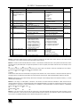
NOTE 19 – After this instruction is sent, the unit will respond to the ASCII command set defined by the OUTPUT byte. The
ASCII command to operate with the HEX command set must be sent in order to return to working with HEX codes.
NOTE 20 – When data (ie. the INPUT and/or OUTPUT bytes) of more than 7 bits is required, this instruction is sent before
sending the instruction needing the additional bits. The data in this intruction then becomes the Most Significant Bits of that
next instruction. For example, to set the audio gain (instruction 22) of output 3 to 681dec (2A9hex), you would first send HEX
codes
3F
80
85
81
and then send HEX codes
16
83
A9
81.
To set the audio gain of output 6 to 10013dec (271Dhex), first send HEX codes
3F
80
CE
81
followed by HEX codes
16
86
9D
81.
NOTE 21 – To store data in the non-volatile memory of the unit, eg. the EEPROM for saving SETUPS. The EEPROM
address is sent using the INPUT byte, and the data to be stored is sent using the OUTPUT byte. To use this instruction, it is
necessary to understand the memory map, and memory structure of the particular machine.
NOTE 22 – Instruction 59 and instruction 60 load data for sending to the crosspoint switcher (or for storing in a SETUP), ie.
the data is “lined-up” to be executed later. Instruction 58 executes the loaded data.
NOTE 23 – If the INPUT byte is set as 127dec, then the data stored in a SETUP is loaded. The SETUP # is in the OUTPUT
byte.
NOTE 24 – Further information needed in instructions 21, 22, 25 and 26, is sent using instruction 42 – which is sent prior to
the instruction. For example, to request the audio gain value of right input # 9, send hex codes
2A
84
80
81
and then send HEX codes
19
89
81
81.
NOTE 25 – For units which detect the validity of the video inputs, Instruction 16 will be sent whenever the unit detects a
change in the state of an input (in real-time).
For example, if input 3 is detected as invalid, the unit will send the HEX codes
10
83
84
81
If input 7 is detected as valid, then the unit will send HEX codes
10
87
85
81.
19