1
EDSIM ++
User Guide
N.C. Punt
May 2013
Title
Author
Revision
Date
Status
Edsim++ user guide
N.C. Punt
1.02
16-09-2013
First print
MEDIWARE
Document History
DOCUMENT HISTORY
Revision
Date
Author
Description
1.00
30-05-2013
N.C. Punt
First print
1.01
13-06-2013
N.C. Punt
First revision
1.02
16-09-2013
N.C. Punt
Corrected header
-ii-
MEDIWARE
Table of Contents
TABLE OF CONTENTS
1
INTRODUCTION ................................................................................................................................................... 5
1.1
1.2
1.3
2
INSTALLATION .................................................................................................................................................... 6
2.1
2.2
2.3
2.4
3
LAUNCH EDSIM++ .............................................................................................................................................. 10
OPEN A MODEL ................................................................................................................................................... 10
SIMULATE A MODEL ........................................................................................................................................... 11
MODIFY A MODEL............................................................................................................................................... 14
DECORATE A MODEL .......................................................................................................................................... 15
EDSIM++ DESKTOP ........................................................................................................................................... 16
4.1
4.2
4.3
4.4
4.5
4.6
4.7
4.8
4.9
4.10
4.11
5
SYSTEM REQUIREMENTS ....................................................................................................................................... 6
INSTALLATION FOLDER ......................................................................................................................................... 6
INSTALLATION PROCEDURE .................................................................................................................................. 6
INSTALL LICENSE .................................................................................................................................................. 9
QUICK START ..................................................................................................................................................... 10
3.1
3.2
3.3
3.4
3.5
4
DOCUMENT PURPOSE ............................................................................................................................................ 5
DOCUMENTS SCOPE .............................................................................................................................................. 5
EDSIM++ MISSION ................................................................................................................................................ 5
OVERVIEW .......................................................................................................................................................... 16
ADDING OBJECTS ................................................................................................................................................ 17
MANIPULATING OBJECTS .................................................................................................................................... 17
CONNECTING OBJECTS ........................................................................................................................................ 17
SELECTING MULTIPLE OBJECTS .......................................................................................................................... 19
DUPLICATING AND DELETING SELECTED OBJECTS ............................................................................................. 19
OBJECT NAME & TYPE ........................................................................................................................................ 19
OBJECT PROPERTIES ............................................................................................................................................ 20
TOOLBAR BUTTONS ............................................................................................................................................ 21
MENU ITEMS ....................................................................................................................................................... 21
ERROR MESSAGES ............................................................................................................................................... 23
EDSIM++ MODELS ............................................................................................................................................. 24
5.1 MODEL STRUCTURE ............................................................................................................................................ 24
5.2 OBJECT CATEGORIES .......................................................................................................................................... 24
5.3 SYMBOL CATEGORIES ......................................................................................................................................... 25
5.4 EDITING MODEL PROPERTIES .............................................................................................................................. 25
5.4.1
Obj - Object Tab .................................................................................................................................. 25
5.4.2
Var - Variables Tab.............................................................................................................................. 26
5.4.3
Par: Parameters Tab............................................................................................................................ 27
5.4.4
Pop: Population Parameters Tab ........................................................................................................ 28
5.4.5
Con: Constants Tab.............................................................................................................................. 28
5.4.6
Opt: Options Tab ................................................................................................................................. 28
5.4.7
Obs: Observations Tab ........................................................................................................................ 28
5.4.8
Ext: Externals Tab ............................................................................................................................... 29
5.4.9
Sim: Simulation Tab ............................................................................................................................. 30
5.4.10
Fit: Fitting Tab..................................................................................................................................... 32
5.4.11
App: Application Tab ........................................................................................................................... 32
6
BUILDING MODELS .......................................................................................................................................... 33
6.1
6.2
6.3
6.4
6.5
7
ONE-COMPARTMENT MODEL .............................................................................................................................. 33
TWO-COMPARTMENT MODEL ............................................................................................................................. 35
AREA UNDER THE CURVE (AUC) ....................................................................................................................... 35
TIME ABOVE LEVEL ............................................................................................................................................ 36
EFFECT ................................................................................................................................................................ 37
RESULTS VIEWER ............................................................................................................................................. 38
-iii-
MEDIWARE
7.1
7.2
7.3
8
FILE FORMATS .................................................................................................................................................... 41
FORMAT SELECTION............................................................................................................................................ 41
EXCEL EXPORT ................................................................................................................................................... 42
FITTING MODELS TO OBSERVATIONS ...................................................................................................... 43
9.1
9.2
9.3
9.4
10
MICROSOFT EXCEL COMPATIBLE WORKBOOK.................................................................................................... 38
WORKBOOK DESIGNER MODE ............................................................................................................................ 39
DUAL MONITOR SUPPORT ................................................................................................................................... 39
MODELS STORAGE ........................................................................................................................................... 41
8.1
8.2
8.3
9
Table of Contents
ADDING OBSERVATIONS ..................................................................................................................................... 43
SELECTING PARAMETERS .................................................................................................................................... 43
ADJUST SETTINGS ............................................................................................................................................... 43
FITTING RESULTS ................................................................................................................................................ 43
EDSIM++ PLUG-INS ........................................................................................................................................... 44
10.1 MONTE CARLO SIMULATOR ................................................................................................................................ 44
10.2 DOSE CALCULATOR ............................................................................................................................................ 44
11
PROGRAMMING EDSIM++ .............................................................................................................................. 45
11.1 MACROS .............................................................................................................................................................. 45
11.2 OBJECTS .............................................................................................................................................................. 46
12
APPENDICES ....................................................................................................................................................... 47
12.1 EDSIM++ ERROR MESSAGES ............................................................................................................................... 47
-iv-
MEDIWARE
Introduction
1
INTRODUCTION
1.1
Document Purpose
This document is the Edsim++ user guide. It shows the user how to design and run basic PKPD
models using Edsim++. Advanced modeling examples are given in the accompanying video
tutorials (http://www.mediware.cz).
1.2
Documents Scope
This document is limited to describing the basic operations in Edsim++. It does not represent an
advanced PKPD modeling instruction.
1.3
Edsim++ Mission
Edsim++ is an object oriented visual pharmacokinetic-pharmacodynamic modeling tool for use in
education and research. Edsim++ discriminates itself from other PKPD modeling software for the
following reasons:
Edsim++ is not a universal modeling tool that can be used in multiple application domains.
Instead, Edsim++ focusses on PKPD modeling applications.
This clear unambiguous choice resulted in a very easy to use, yet powerful, application.
Edsim++ can be used for a broad range of PKPD modeling problems
The Edsim++ PKPD object library can be extended by the end user (library).
The Edsim++ application can be extended by programmers (plug-ins).
Edsim++ is very suitable for use in research and education.
-5-
MEDIWARE
Installation
2
Installation
2.1
System Requirements
Edsim++ requires the Microsoft.NET framework version 4.0 to be installed on your system. You
can download this package at www.microsoft.com/download.
2.2
Installation Folder
You can install Edsim++ on any folder on your system. This can also be a USB memory stick.
2.3
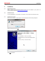
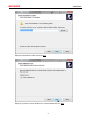
Installation Procedure
Double-click the Edsim++ setup program. The setup language selection dialog will appear.
Select the language and click OK.
Click Next to continue.
-6-
MEDIWARE
Installation
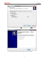
Specify the destination location and click Next.
Specify if you want to have a desktop icon (recommended) and click Next.
-7-
MEDIWARE
Installation
Review your installation settings. Click Back to modify these or click Install to continue.
You can directly launch Edsim++ after the installation has been completed.
-8-
MEDIWARE
2.4
Installation
Install License
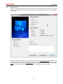
Edsim++ will stop working after a 30 days trial period. You must purchase a license in order to
continue using Edsim++. The Edsim++ about screen is automatically shown when the trial period
has expired.
Email the displayed Hardware ID to the vendor. Simply click Copy Hardware ID and paste it into
your email program. The license file will be send to you by email as an attachment. Save this
attachment to disk and click the Install License button in Edsim++. Select the license file and click
Open. Now you will have a licensed copy of Edsim++ so that you can continue using it.
-9-
MEDIWARE
Quick Start
3
QUICK START
3.1
Launch Edsim++
Double-click on the Edsim++ icon on the windows desktop in order to start the application.
Edsim++
The application window will appear.
3.2
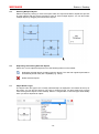
Open a Model
Click on the File menu and select Open Model (File>Open>Model) or click on the open model
button in the toolbar.
File>Model>Open
Open Model Button
-10-
MEDIWARE
Quick Start
Select the Demo.edx file in the open file dialog and click Open.
A standard 4-compartment model will be displayed on the Edsim++ desktop.
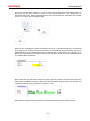
3.3
Simulate a Model
Now start a simulation by clicking the Run button:
-11-
MEDIWARE
Quick Start
The progress of the simulation is displayed in the progress bar at the bottom. A chart will appear
after the simulation has been completed showing the concentration in all 4 compartments.
Click on the Output tab at the bottom of the screen in order to view the simulation output as a table.
Click on the Model tab at the top. The model appears again.
-12-
MEDIWARE
Quick Start
Now click on the Mini Charts button in the toolbar:
This will show the curves (concentration) in the object (compartment) they are associated with
thereby supplying the user with a spatial view. Now double-click the TInjection object I01. The
object properties window will appear from the right side.
-13-
MEDIWARE
3.4
Quick Start
Modify a Model
Add another event (dosing) sequence of 5 times 150 mg every 12 hours starting at 100 h.
Now start another simulation by clicking the Run button:
Click the right mouse button to bring up a magnifying glass.
-14-
MEDIWARE
3.5
Quick Start
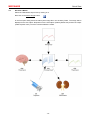
Decorate a Model
Select the TElimination object O01 by clicking on it.
Now click on the Select Image button:
In the File Open dialog select the kidney.wmf image file in the Anatomy folder. The image will be
displayed in the O01 object. Repeat this for the C04 object (Anatomy\Brain.wmf) and the I01 object
(Admin\Injection.wmf). You have now decorated the model.
-15-
MEDIWARE
Edsim++ Desktop
4
EDSIM++ DESKTOP
4.1
Overview
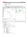
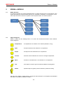
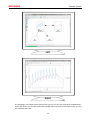
Below is an image of the Edsim++ desktop. All important elements are clearly identified.
Main GUI elements:
1.
2.
3.
4.
5.
6.
7.
8.
Model desktop
Object properties (category tab is 8)
Error messages
Object templates (can be dragged to the model desktop)
Main menu
Tool bar
Model view tabs (model diagram, result data and plug-ins)
Object property category tabs.
a.
b.
c.
d.
e.
f.
g.
h.
i.
j.
k.
Obj
Var
Par
Pop
Con
Opt
Obs
Ext
Sim
Fit
App
: Object
: Variables
: Parameters
: Population parameters
: Constants
: Options
: Observations
: Externals
: Simulation settings
: Fit settings
: Application settings (plot, colors, etc.)
-16-
MEDIWARE
4.2
Edsim++ Desktop
Adding Objects
You can add objects to a model by dragging an object template on the desktop. Release the left
mouse button at the position where you want to place to object.
1. Select the template
4.3
2. Drag it on the desktop
3. Release the mouse button
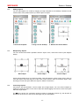
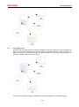
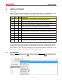
Manipulating Objects
You can conduct three basic operations with an object: move, resize and connect (see diagram
below).
Move object
Resize object
Connect object
Anchor points appear when you select an object. Click and drag the center anchor point in order to
move the object. Click and drag one of the outer anchor points in order to resize the object. Click
and drag on some free space within the object to initiate a connection.
4.4
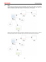
Connecting Objects
Connections are links between a source object and a target object. You can connect objects by
clicking on some free space in the source object and start dragging the mouse to some free space
within the target object.
The sign is shown if a connection cannot be made in a particular context. E.g. the direction of
the link can be incorrect or the source and target may be incompatible.
-17-
MEDIWARE
Edsim++ Desktop
1 Click on source
2 Start dragging
3 Drag to target
4 Release button
Incorrect Direction
Incompatible Objects
-18-
MEDIWARE
Edsim++ Desktop
4.5
Selecting Multiple Objects
Select an object by clicking on some free space within the object boundaries. Repeat this process
for other objects with the Ctrl key pressed in order to select multiple objects. You can also select
multiple objects by dragging a box around the objects.
4.6
Duplicating and Deleting Selected Objects
Select one or more objects and press one of the following buttons on the toolbar.
Duplicates selected objects (including property values). The new and original objects will be
automatically linked if they are compatible (e.g. TSink).
Delete selected objects.
4.7
Object Name & Type
The object name and type of the currently selected object is displayed in the toolbar at the top of
the screen. You can give the object a new name or change its type. An object must have a unique
name among all the objects on the desktop. Edsim++ will generate a name and type automatically
when you add or duplicate an object.
-19-
MEDIWARE
4.8
Edsim++ Desktop
Object Properties
Double-clicking an object brings up the object properties window from the right side. Clicking the
the button hides this window again. Double-clicking on some free space on the model desktop
toggles the visibility of this window.
The tabs in object properties window represent different categories of properties.
Obj
Var
Par
Pop
Con
Opt
Obs
Ext
Sim
Fit
App
: Object (dosing sequences)
: Variables (select which variables must be observed during a simulation)
: Parameters (select which parameters must be fitted during a fit)
: Population parameters (used in Bayesian estimation)
: Constants (constant symbol values)
: Options (named symbol values)
: Observations (measurement values that can be fitted)
: Externals (constitute the interface between objects)
: Simulation settings (simulation method)
: Fit settings (fit method)
: Application settings (plot, colors, etc)
-20-
MEDIWARE
4.9
Edsim++ Desktop
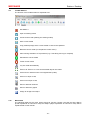
Toolbar Buttons
The function of the toolbar buttons is explained here.
Exit Edsim++
Open an existing model
Create a new model (clearing the existing model)
Save current model
Copy a bitmap image of the current model or chart to the clipboard
Build the current model (or compile the current macro)
Abort running simulation or fit procedure (e.g. if it is taking too long to complete)
Simulate the current model
Fit the current model
Lay-out model automatically
Zoom to fit. Zoom in or out so that all model objects are visible.
Cancel zoom. Restore zoom to its original state (100%)
Zoom in in steps of 10%
Zoom out in steps of 10%
Show or hide link numbers
Show or hide mini graphs
Assign an image to an object
4.10
Menu Items
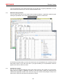
The following table lists all menu entries and their function. Please note that the terms Macro
(model expressed as C# source code) and Object (object expressed as C# source code) will be
explained later in this manual.
-21-
MEDIWARE
Edsim++ Desktop
Level 1
Level 2
Level 3
Description
File
New
Model
Create a new model
Macro
Create a new macro
Object
Create a new object
Model
Open an existing model from file
Macro
Open an existing macro from file
Object
Open an existing object from file
Model
Close current model
Macro
Close current model
Object
Close current object
Model
Save current model to file using the existing name
Macro
Save current macro to file using the existing name
Object
Save current object to file using the existing name
Model
Save current model to file using a new name
Macro
Save current macro to file using a new name
Object
Save current object to file using a new name
Model
Print current model
Results
Print current results set
Open
Close
Save
Save As
Print
Model
Macro
Object
Help
Restart
Restart Edsim++ (required after a library build)
Exit
Ext Edsim++
Build
Build the current model
Convert to Macro
Convert the current model to a macro (C# source)
Run
Build and simulate the current model
Fit
Build and fit the current model
Insert Object
Insert object declaration into macro C# code
Build
Compile the current macro
Convert to Model
Convert the current macro to a model
Run
Build and simulate the current macro
Fit
Build and fit the current macro
Build
Compile the current object
Build Library
Build library by compiling all available objects
Restore Library
Restore the factory default library
About Edsim++
Show version and license information
-22-
MEDIWARE
4.11
Edsim++ Desktop
Error Messages
Error messages are displayed in a window at the bottom of the desktop. Click on some free space
on the model desktop or on the button to hide this window again. A complete list of possible
error messages is given in Appendix 12.1.
An attempt to start a simulation in the example above will result in an error message because the
TPeripheral object was not linked to the TCompartment object.
-23-
MEDIWARE
Edsim++ Models
5
EDSIM++ MODELS
5.1
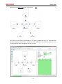
Model Structure
The generic structure of a model is displayed below. A model consists of one or more objects, each
object representing a particular PKPD process (e.g. absorption, distribution or elimination). In turn,
each object is built of a number of symbols. These symbols used in the PKPD equations.
Model
5.2
Object 1
Symbol 1
Object 2
Symbol 2
Object 3
Symbol 3
Object N
Symbol N
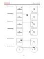
Object Categories
Edsim++ objects are the building blocks of a model. We discriminate between seven different
object categories.
Compartment
A compartment is a container for a material (substance, drug)
Input
An input introduces new material in a compartment
Output
An output removes material from a compartment
Transfer
A transfer moves material from a source to a target compartment
Effect
An effect is calculated from a concentration in a compartment
Tool
A tool object is used for generic tasks like addition and integration
Patient
A patient object is typically used for allometric parameter scaling
We refer to the “Edsim++ PKPD-Library” manual and video tutorials for a complete list and detailed
description of all objects available in Edsim++.
-24-
MEDIWARE
5.3
Edsim++ Models
Symbol Categories
Symbols are the building blocks of an object and are used in equations defined within that object.
We discriminate between the following symbol categories.
Type
Subtype
Description
Constants
Event Constants
Invariant symbols used in event equations
Option Constants
Invariant symbols used for setting object options
Fittable Parameters
Time-invariant symbols that can be fitted
Non-Fittable Parameters
Time-invariant symbols that cannot be fitted
Interpolated Variables
Time variant symbols that must interpolated
Differential Variables
Time variant symbols that must be integrated
Parameters
Variables
5.4
Editing Model Properties
5.4.1
[Obj]: Object Tab
Here you can specify the name and molecular weight of the substance. You can mark an object as
being an “interactant” so that it can be discriminated from another object of the same type
participating in an interaction. Also the display color can be set here.
Objects can be synchronized to events occurring in other objects (the synchronization object). This
sync mechanism is typically used to reset a calculated AUC or average concentration using events
occurring in an input object.
Some objects support events. A number of event sequences can be entered in the event table. The
timing of these sequences may overlap each other, allowing for very complex time tables. The
example above represent an infusion dosing schedule in which 100 mg (Dose) is given at time 4 h
(Tnul) for a duration of 1 h (Tdur) with an interval time of 8 h (Tint). In total 10 dosages are given
(Ndos). These event values are considered to be a special kind of constants (event constants).
-25-
MEDIWARE
5.4.2
Edsim++ Models
[Var]: Variables Tab
The variables tab lists all the variables associated with the selected object. Here you can change
the initial value and the unit of the variable. You can also mark variables as Observed (Obs) so that
it is shown in the output chart. The Axis property assigns the variable to the left y-axis (unchecked,
default) or right y-axis (checked).
You can select a curve color for a variable when you click on the Color box. A white color means
that the colors are assigned automatically by Edsim++.
By increasing the object properties window size additional properties are revealed. Here you can
enter the population value of the variable. Variable population values are used for allometric scaling
of parameters (see next paragraph).
-26-
MEDIWARE
5.4.3
Edsim++ Models
[Par]: Parameters Tab
The parameters tab lists all the parameters associated with the selected object. Here you can
change the value, standard deviation and unit of the parameter. Check the Fit box if you want to
estimate the parameter during fitting. Check the Log box to indicate that the parameter is lognormally distributed (used in Monte Carlo simulations).
By increasing the object properties window size additional properties are revealed. Here you can
select the symbol used for allometric scaling of the parameter. Also an allometric scaling factor can
be specified. Finally the display format for the scaled unit can be entered (0, 1, 2 or 3).
Below are the units from this example using different format values:
0:
L/kg
1:
L/kgBw
2:
L/70kg
3:
L/70kgBw
In this example the volume of distribution (V) is scaled using the patient body weight (Bw). The
generic scaling expression is given below.
(
)
This can be simplified if Factor = 1 and Bwpop = 70 kg. We added the units between square
brackets for the sake of clarity.
Finally we can rearrange this to the classical denormalization formula.
-27-
MEDIWARE
5.4.4
Edsim++ Models
[Pop]: Population Parameters Tab
The population parameters tab lists the same parameters as the parameters tab. However, in this
screen the parameter population values and population standard deviations can be entered. These
values are used with Bayesian estimation.
5.4.5
[Con]: Constants Tab
The constants tab lists all the constants associated with the selected object. Here you can change
the value and unit of the constant. In the example above the constant fraction unbound (fu) for
compartment C01 is displayed.
5.4.6
[Opt]: Options Tab
The options tab lists all the options associated with the selected object. Options are a special kind
of constants in which the values are associated with a name. The can be regarded as so called
enumerations. The example above lists all options associated with a patient object.
5.4.7
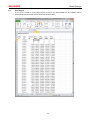
[Obs]: Observations Tab
The observations tab lists all the observations associated with the selected object. Observations
are organized in a matrix in which the first column represents the observation time. Subsequent
columns hold the values for a particular variable which can be selected on the top row of the table.
You are completely free where to enter your data in the table. In the following example first the
values for C01.C were entered. Then a second table with C01.Cu values was added.
-28-
MEDIWARE
Edsim++ Models
Now if you leave the observations tab by clicking on another tab (e.g. object tab) and come back
again to the observations tab you will see that all observations have been sorted. Simply leave
cells blank on time points where you do not have a variable value.
5.4.8
[Ext]: Externals Tab
-29-
MEDIWARE
Edsim++ Models
The externals tab lists all the externals associated with the selected object. Externals are symbols
that are required by an object but are defined in another object. So the list of external symbols
represents the interface of an object.
The previous example shows the externals of a TElimination output object O01. This elimination
object requires the amount A and volume V symbols of a connected source compartment. Within
the elimination object these symbols are referenced as Ax and Vx. In this example the external
name is fixed and cannot be changed by the user.
The following example shows the externals of a TIntegrator tool object. Here the user is free to
change the externally referenced symbol name used for integration.
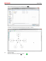
5.4.9
[Sim]: Simulation Tab
-30-
MEDIWARE
Edsim++ Models
This screen displays all simulation settings. In the primary section the simulation duration,
resolution and integration method can be specified. Edsim++ will establish a simulation duration
automatically when a value of 0 is entered here. The automatically derived simulation duration is
based on the number of events and event time interval.
In the secondary section more low level simulation settings can be specified. These settings
directly control the integrator which is used for solving the differential equations. In the outputs
section the user can specify when the simulator should generate an output value. Normal outputs
are driven by the selected simulation resolution. Observation and event outputs are triggered by
the occurrence of an event or observation at a particular time.
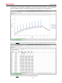
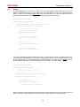
The profiling section contains the settings for the profile simulation mode. In this mode additional
outputs can be generated at particular time points. These additional values are outputs at Ttrough,
Tpeak and Tmax. Ttrough and Tpeak outputs also require the “observation outputs” setting to be
checked. Also an event object and profile variable must be specified. Below is a typical setup for a
profile simulation in which only the normal outputs have been disabled.
This yields the following results in a 4-compartment model with extravascular administration
(dosing interval time is 8 hours) over a period of 2 dosing intervals.
-31-
MEDIWARE
5.4.10
Edsim++ Models
[Fit]: Fitting Tab
This screen displays all fitting settings like fitting method (Simplex or Marquardt), stop criterion and
the maximum number of allowed iterations (0 means no limitation).
5.4.11
[App]: Application Tab
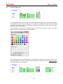
In the diagram section of the application tab the default color for the desktop, objects and links can
be specified. Please note that the color for individual objects can be controlled in the object tab.
In the plot section the user can select which symbol is the x-variable (default Tsim) and which
symbol is the y-variable (default blank). A blank entry for y-variable means that all observed
variables will be shown in the chart. The user can also specify if an axis should be log scaled and if
grid lines should be displayed.
In the export section the user can specify if the application supporting a particular export format
should be automatically launched after the export has been completed.
-32-
MEDIWARE
Building Models
6
BUILDING MODELS
6.1
One-compartment Model
Start Edsim++ and drag the following objects on the desktop: a compartment, an input and an
output.
Now connect injection I01 (source) with the compartment C01 (target). Next connect compartment
C01 (source) with the elimination O01 (target).
Next click on the mini chart button
followed by the run button
-33-
(on the toolbar)
MEDIWARE
Building Models
One of the great features of Edsim++ is that all objects are equipped with smart default values so
that when you are done building a model you can directly simulate it. Now double-click the
elimination object O01. Select the parameters tab (Par) and increase the elimination rate constant
from 0.1 to 0.5 (1/h). Run a simulation again.
Note how the concentration profile has changed. Now click on the Results tab at the top followed
by clicking on the Symbols sub-tab at the bottom of the application window. Closely look at the
parameters lists. All non-default parameters are marked with a yellow color. This will help you to
identify those parameters you forgot to enter yourself. Please note that all data in the Results tab is
only updated after a simulation.
Now double-click the elimination object O01 again. Select the options tab (Opt) and change the
Mode option from Rate to Clearance. Now select the parameters tab (Par) again. Note how the rate
constant k (1/h) has been replaced with clearance CL (L/h).
Many Edsim++ objects support this feature of switching between rate and clearance mode.
-34-
MEDIWARE
6.2
Building Models
Two-Compartment Model
Continue with the 1-compartment model from the previous paragraph. Drag another compartment
on the desktop.
nd
Please note that the 2 compartment is automatically created as a peripheral compartment. Now
connect compartment C01 (source) with compartment C02 (target) and run a simulation.
Note that the connection between the central compartment C01 and the peripheral compartment
C02 is bidirectional, which means that material can flow in both directions. However, it is important
to realize that formally C01 is still is the source object and C02 still the target object, even though
the connection is bidirectional.
6.3
Area Under the Curve (AUC)
Continue with the 2-compartment model from the previous paragraph. Now drag a tool object on
the desktop. Connect compartment C01 with the integrator tool X01. Double-click the integrator tool
and select the variables tab (Var). Mark variable AUC as observed and run a simulation.
-35-
MEDIWARE
6.4
Building Models
Time Above Level
Continue with the model from the previous paragraph. Select the integrator tool and changes its
type to TLevel. Double click the level tool and select the variables tab (Var). Enter a value of 10
mg/L for the LEVEL variable and uncheck its observed status. Next check the observed status of
the RTAL variable (relative time above level).
The level tool is typically used for calculating the time above MIC (t>mic) of antibiotic drugs.
-36-
MEDIWARE
6.5
Building Models
Effect
Continue with the model from the previous paragraph. Now drag an effect object on the desktop.
Connect peripheral compartment C02 with effect object E01. Double-click the effect object and
select the variables tab (Var). Mark variable E as observed and run a simulation.
Double-click the effect object again and select the parameter tab (Par). Enter a value of 1 mg/L for
the EC50 parameter and run a simulation again. Note how the effect levels have increased.
-37-
MEDIWARE
Results Viewer
7
RESULTS VIEWER
7.1
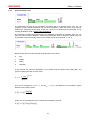
Microsoft Excel Compatible Workbook
The results tab of Edsim++ is in fact a fully featured spreadsheet that is 100% compatible with
Microsoft Excel.
-38-
MEDIWARE
Results Viewer
You can do all things in the results viewer that you can also do in regular spreadsheets. You can
enter formulas into cells but you can also create embedded charts.
7.2
Workbook Designer Mode
You can create a 2nd copy of the results viewer outside the Edsim++ application window by right
clicking the spreadsheet. Then select Workbook Designer from the context menu.
In the external results viewer you have now full access to the spreadsheet menu. Please note that
both viewers remain in sync with each other. If you type something in one spreadsheet it will also
appear in the other one and vice versa.
7.3
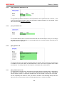
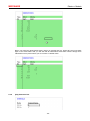
Dual Monitor Support
We can use the workbook designer mode of the results viewer for the creation of a dual monitor
setup. Move the Edsim++ application window to the left monitor. Select the model tab and
maximize the application window. Now move the copy of the results view (designer mode) to the
right monitor. Select the chart tab and maximize the window.
-39-
MEDIWARE
Results Viewer
LEFT
RIGHT
The advantage of this dual monitor setup is that you can now see two chart types simultaneously.
On the left monitor you see the model with a spatial chart view while on the right monitor you see
the combined chart view.
-40-
MEDIWARE
Model Storage
8
MODELS STORAGE
8.1
File Formats
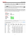
Edsim++ supports a number of different file formats for storing models. The following table shows
which file formats you can save and/or open with Edsim++ (Ext stands for file extension).
Ext
Save
Open
Description
edx
+
+
Default Edsim++ format (XML). Includes layout and graphics.
xml
+
+
Bare model format (XML). Like edx but without layout and graphics.
cs
+
+
Source code model format (C#). Same data as xml format.
dll
+
+
Binary library model format (.NET). Same data as xml format.
exe
+
-
Binary executable format (.NET). Requires MS Excel to run.
xls(x)
+
-
Excel BIFF (xls) or XML (xlsx) format. Includes image, charts and data.
vdx
+
-
Visio XML format. Only contains a diagram of the model.
wmf
+
-
Windows Meta File format. Only contains a picture of the model.
pdf
+
-
Portable Document Format. Only contains a picture of the model.
png
+
-
Portable Document Format. Only contains an image of the model.
The eds, xml, cs and dll formats can be saved and opened by Edsim++. All other formats can only
be saved which makes them essentially one way tickets. We refer to them as export only formats.
Only the Edsim++ native edx format is capable of storing graphical model layout information. If you
open xml, cs or dll files, a new layout will be automatically generated.
8.2
Format Selection
In the file Save As dialog you can select the file format in the Save as type field. Enter a file name,
select the desired format and click Save to store the model on disk. The Open dialog works in the
same way.
-41-
MEDIWARE
8.3
Model Storage
Excel Export
If you save a model in Excel xls(x) format, Excel (or any other default xls file handler) will be
automatically launched after the file has been saved to disk.
-42-
MEDIWARE
Programming Edsim++
9
FITTING MODELS TO OBSERVATIONS
9.1
Adding Observations
9.2
Selecting Parameters
9.3
Adjust Settings
9.4
Fitting Results
-43-
MEDIWARE
10
EDSIM++ PLUG-INS
10.1
Monte Carlo Simulator
10.2
Dose Calculator
Programming Edsim++
-44-
MEDIWARE
Programming Edsim++
11
PROGRAMMING EDSIM++
11.1
Macros
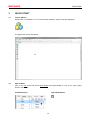
Edsim++ models can also be represented in the C# programming language. We refer to such
models as macros. Macros can be created from scratch within the Edsim++ application. There is
no need for a separate development environment like Visual Studio. A default macro template is
generated when you select New Macro from the File menu.
using
using
using
using
using
using
using
System;
System.Linq;
Mediware.Edsim.ModLib;
Mediware.Edsim.ModObj;
Mediware.Edsim.ModWrk;
Mediware.Edsim.ModSim;
Mediware.Edsim.ModFit;
namespace Mediware.Edsim.Model
{
public class TUserModel : TWorkModel
{
// Input
public TInjection I1 = new TInjection();
// Output
public TElimination O1 = new TElimination();
// Compartments
public TCompartment C1 = new TCompartment();
// Connect objects
public override void Connect()
{
Link(I1, C1);
Link(C1, O1);
}
// Pre-connect initialization.
public override void Init()
{
I1.AddEvent(100, 0, 0, 8, 10);
}
// Post-connect initialization.
public override void Final()
{
}
// Simulator initialization
public override void InitSim(SimSet settings)
{
}
// Fitter initialization
public override void InitFit(FitSet settings)
{
}
}
}
The model above is a simple 1-compartment model with an injection input and an elimination
output. The injection object defines an event sequence of 10 times 100 mg every 8 hours. You can
use this as a starting point when building your own models in C#.
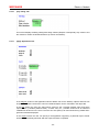
As an alternative, you can also convert an existing model diagram into a macro by selecting
Convert to Macro from the Model menu. You can use this feature to learn of complex models can
be represented in C#.
-45-
MEDIWARE
11.2
Programming Edsim++
Objects
In model diagrams and macros you make use of existing PKPD objects which are part of the
Edsim++ PKPD object library. These objects are also programmed in C#. You can create a new
object in Edsim++ by selecting New Object from the File menu. You will be presented with an
empty object template than can serve as a starting point for your own objects.
using Mediware.Edsim.ModLib;
namespace Mediware.Edsim.ModObj
{
[Description("Edsim++ Object definition template.")]
public class TMyCompartment : BCompartment
{
// Symbol declaration go here
// Pre-connect initialization.
public override void Init()
{
}
// Post-connect initialization
public override void Final()
{
}
// Normal Equations
public override void CalcNorm()
{
}
// Differential Equations
public override void CalcDiff()
{
}
}
}
You must recompile the PKPD object library when you want to add a new or modified object to it.
You must then restart Edsim++ in order to use the updated library. You can view the source code
of any existing object in a model diagram by double-clicking it. You then click the Code button in
the object tab (Obj). Below you see an example of the code for an injection object.
using Mediware.Edsim.ModLib;
namespace Mediware.Edsim.ModObj
{
/// <summary>
/// IV bolus injection input class.
/// </summary>
[Description("IV bolus injection input class.")]
public class TInjection : TInput
{
/// <summary>
/// Execute on-event.
/// </summary>
public override void EventOn()
{
Ay.Value = Ay.Value + Dose.Value;
}
}
}
Macro and object code is actually beyond the scope of this manual. But you can already learn a lot
from converting model diagrams into macros and by viewing the code of existing objects.
-46-
MEDIWARE
Appendices
12
APPENDICES
12.1
Edsim++ Error Messages
Library
Exception
Message
ModLib
LinkSourceException
Object A cannot be the source of target object B. Source must be of type: T.
LinkTargetException
Object A cannot be the target of source object B. Target must be of type: T.
LinkInCountException
Object A cannot have more than N source(s).
LinkOutCountException
Object A cannot have more than N target(s).
UnresolvedSymbolException
Symbol S in object A has not been resolved by any of the connected objects.
Objects may be incompatible or links missing.
InstanceNotAllowedException
Object A is of type T. You are not allowed to create instances of this type
because it is marked with the NoInstance attribute.
OneInstanceAllowedException
Only one object of type T is allowed because it is marked with the OneInstance
attribute.
CircularReferenceException
Parameters P and Q reference each other for sharing (circular reference).
HiddenFieldException
Hidden field F detected in class C. This is not allowed. Rethink inheritance
strategy.
UnknownObjectException
Reference to unknown object A.
UnknownSymbolException
Reference to unknown symbol S.
NumLib
IterationException
Too many steps in procedure P.
ModSim
UserAbortException
The simulation was aborted by the user.
SteadyStateAbortException
The simulation was aborted because steady state was reached.
LevelDetectException
Level detection is enabled without setting a trigger variable
SmallStepException
Step size of s too small at time t
ModWrk
-47-