1
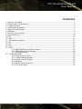
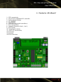
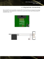
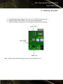
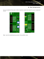
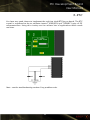
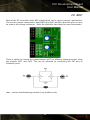
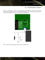
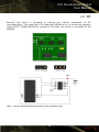
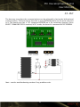
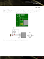
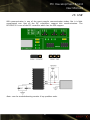
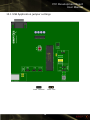
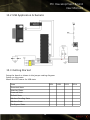
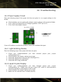
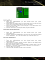
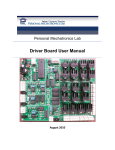
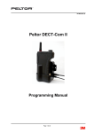
PIC Development Board
User Manual
PIC Development Board
User Manual
Version 1.0
1
PIC Development Board
User Manual
Contents
1. Features On Board.....................................................................................................3
2. Programmer Connectivity..........................................................................................4
3. Getting Started..........................................................................................................5
4. Light Emitting Diodes................................................................................................6
5. Liquid Crystal Display................................................................................................7
6. Switches...................................................................................................................8
7. Serial Communication...............................................................................................9
8. Port Extensions.......................................................................................................10
9. RTC........................................................................................................................11
10. ADC......................................................................................................................12
11. Temperature Sensor..............................................................................................13
12. SPI........................................................................................................................14
13. I2C.......................................................................................................................15
14. PS2.......................................................................................................................16
15. USB.......................................................................................................................17
15.1 USB Application jumper settings...............................................................18
15.2 USB Application Schematic........................................................................19
15.3 Getting Started.........................................................................................19
16. Troubleshooting...................................................................................................20
16.1 Power Supply Circuit................................................................................20
16.2 Light Emitting Diodes..............................................................................20
16.3 Liquid Crystal Display...............................................................................20
16.4 Switches...................................................................................................21
16.6 Serial Communication..............................................................................21
16.7 Port Extensions........................................................................................21
2
PIC Development Board
User Manual
1. Features On Board
1. ICSP connectivity
2. Any 40 pin compatible PIC controller.
3. Serial communication
4. I2C EEPROM
5. SPI EEPROM
6. USB (with supported controllers)
7. PS/2 connectivity
8. Voltage references (Vref+, Vref-)
9. RTC crystal
10. Temperature sensor
11. 16x2 LCD connectivity.
12. Led array.
13. Switches
14. Port extensions
3
PIC Development Board
User Manual
2. Programmer Connectivity
Most of the PIC microcontrollers supports ICSP. This board does not support low voltage
programming. The programmer is not built on board due to the future enhancement of
programming circuit.
4
PIC Development Board
User Manual
3. Getting Started
1. Connect the power adapter (12V AC or 9-12V DC) to Power Jack.
2. Switch on the Power Switch, the power led should glow.
3. Once the power led glows you are ready to work with the board.
Note : Refer the troubleshooting section if any problem exist
5
PIC Development Board
User Manual
4. Light Emitting Diodes
Do the following settings to make LEDs work
1. Jumper J1 to Enable LEDs mode.
All the eight LEDs are connected to PORTD of the microcontroller. The anode of the LEDs
are tied to VCC. So to glow the LED you should make the corresponding pin low.
Note : see the troubleshooting section if any problem exits.
6
PIC Development Board
User Manual
5. Liquid Crystal Display
The LCD is connected to PORTB. The type of data communication used here is 4 bit
mode. The connections are as follows
1. Data line are from RB0 to RB3.
2. R/W is directly grounded.
3. The RS pin is connected to R4
4. Enable pin is connected to R5
Note : see the troubleshooting section if any problem exits.
7
PIC Development Board
User Manual
6. Switches
The connection of the switches depends upon the logic level you want as the input to
the controller.
1. If you want HIGH(5V) as the input then
1. Jumper SOURCE to VCC.
2. Jumper PULL to pull down mode.
2. If you want LOW(0V) as the input then
1. Jumper SOURCE to GND.
2. Jumper PULL to pull up mode.
There are 5 switches connected to PORTB. The PORTB pin from RB0 to RB4 are
multiplexed with LCD data lines.
Note : see the troubleshooting section if any problem exits.
8
PIC Development Board
User Manual
7. Serial Communication
This feature enables you to have communication
JP1(RX) and JP2(TX) using the short links.
like USART with the PC. Connect
Note : see the troubleshooting section if any problem exits.
9
PIC Development Board
User Manual
8. Port Extensions
You can extend all the ports of the controller outside the board for your customized
circuit.
Note : see the troubleshooting section if any problem exits.
10
PIC Development Board
User Manual
9. RTC
You have very good chance to implement the real time clock(RTC)ing on board. The RTC
crystal is connected to the to oscillator inputs T1OSO(RC0) and T1OSI(RC1) pins of PIC
microcontrollers. Using this circuitry we can achieve lots of applications which needs
real time.
Note : see the troubleshooting section if any problem exits.
11
PIC Development Board
User Manual
10. ADC
Most of the PIC controllers have ADC inbuilt which can be used in several applications.
The are two presets connected to two PORTA pins RA2 and RA3. Now this pins can also
be used as the voltage references . Refer the controller data sheet for more information.
There is option to connect the potentiometers (POT) to different analog port pins using
the jumpers EXT1 and EXT2. This can be achieved by connecting the EXT pins to
Extension ports.
Note : see the troubleshooting section if any problem exits.
12
PIC Development Board
User Manual
11. Temperature Sensor
You have a provision to connect a temperature sensor LM35 on board. You can even
connect an compatible sensor in place of LM35. But be sure of the pin diagram before
connecting on board. This pin is connected to PORTA, RA0.
Note : see the troubleshooting section if any problem exits.
13
PIC Development Board
User Manual
12. SPI
Basically this board is designed to explore the internal peripherals of PIC
microcontrollers. The board has a SPI supported EEPROM on it. By connecting jumpers
(from SELECT COMM PROTOCOL section) in SPI mode, the board is connected to SPI
EEPROM.
Note : see the troubleshooting section if any problem exits.
14
PIC Development Board
User Manual
13. I2C
The best way to explore the communications can be achieved by having the bidirectional
communication. The best way to have this is using EEPROM where we can write and read
in it. The board even has a I2C supported EEPROM on it. By connecting jumpers (from
SELECT COMM PROTOCOL section) in I2C mode, the board is connected to I2C EEPROM.
Note : see the troubleshooting section if any problem exits.
15
PIC Development Board
User Manual
14. PS2
Using the PS2 protocol we can connect the keyboard or mouse to the controller. The
DATA and CLK pin from the device is not directly connected to the controller just have
different approach of connecting the hardware (polling or interrupt method)
Note : see the troubleshooting section if any problem exits.
16
PIC Development Board
User Manual
15. USB
USB communication is one of the most popular communication today. But it is little
complicated one. Not all the PIC controllers support this communication. The
PIC18F4550 is one of the PIC controller which has the USB support.
Note : see the troubleshooting section if any problem exits.
17
PIC Development Board
User Manual
15.1 USB Application jumper settings
18
PIC Development Board
User Manual
15.2 USB Application Schematic
15.3 Getting Started
Setup the board as shown in the jumper setting diagram.
Switch on the power
Watch the LED status for USB state
State
LED1
Detached State
Attached State
Powered State
Default State
Address Pending State
Address State
Configured State
19
LED2
LED3
LED4
PIC Development Board
User Manual
16. Troubleshooting
16.1 Power Supply Circuit
Take the following steps if the power led does not glow (i.e. no supply voltage to the
board)
Check whether you are getting the adapter output voltage at the anode of diode.
1. If yes, check the output pins of voltage regulators (7805 pin no 3)
2. If no, check the adapter output.
●
If you still unable to resolve the problem contact the hardware designer.
16.2 Light Emitting Diodes
Take the following steps if the power led does not glow.
1. Check your software(whether you have selected
configurations etc,.).
2. Check whether the jumper settings are proper
3. Check the signal level at the pin (you should get 0V).
4. Check the led with the multimeter.
5. Check the LED using multimeter
proper
port,
proper
16.3 Liquid Crystal Display
1. Check your software(whether you have selected proper port, proper
configurations etc,.). Make sure you are using 4 BIT mode of communication
since the hardware is designed for 4 BIT mode.
2. Check whether the jumper settings are proper.
3. Make sure the contrast level is tuned properly
20
PIC Development Board
User Manual
16.4 Switches
1. Check your software(whether you have selected proper port, proper
configurations etc,.).
2. Check whether the jumper settings are proper, Make sure you have set proper
source and the corresponding pulls( i.e. Pull up or pull down).
3. Check the signal level at the pin (you should get 5V if you have choose 5V as
source and 0V if it is GND.
4. Check the continuity by pressing the switch, using the multimeter.
16.6 Serial Communication
1. Check your software(whether you have selected proper port, proper
configurations etc,.).
2. Check the voltage levels at MAX232( if you have 5V as input, then the expected
output of MAX232 is -8 to -12V and the other way round if the input is 0V.
16.7 Port Extensions
1. Check your software(whether you have selected proper port, proper
configurations etc,.).
2. Check whether the jumper settings are proper. Make sure you enable proper
pulls to the external connected circuits.
3. Make sure external hardware is connected with the proper signals from the
baseboard .i.e. Check the connections of VCC, GND and 9-12V (if you use it).
4. Check the signal level at the pin.
5. Check for proper continuity once the circuit is connected.
21