1
3 Advanced Troubleshooting
Replacing the Boards in the TSQ 8000 Instrument
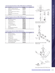
12. Remove and replace the 4-pin feedthrough. You can also remove and replace the o-ring, if
necessary.
13. Reattach the 4-pin feedthrough to the chassis.
14. Replace the large glass manifold cover.
15. Reinsert the RF board by aligning the connectors on the bottom of the board with the
connectors on the distribution board beneath it. It will drop into the slot when it is in the
right position.
16. Push the board down into the connectors.
17. Gently push the board toward the instrument, carefully aligning the board over the
feedthrough pins, until it stops.
18. Reattach the screw holding the RF board to the bracket.
Note This screws is required for good ground contact.
19. Reconnect the wires to the 4-pin connector.
CAUTION - INSTRUMENT DAMAGE: Make sure you reattach these wires to the same
connectors they were attached to before.
20. Reconnect the electrometer board cables.
21. Reattach the top cover and left hand front panels and tighten the screws.
22. Restart your system by following the instructions in “Restarting the System” on page 118.
Tip Once your system is under vacuum and stable, check your RF tune. The new
feedthrough may have slightly different RF characteristics that may shift the RF that is
best for your system.
Thermo Scientific
TSQ 8000 Hardware Manual
279