1
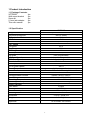
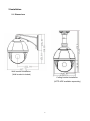
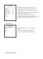
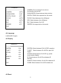
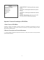
XPTZ22IR Speed dome User Manual Before You Begin Read these instructions before installing or operating this product. Note: This installation should be made by a qualified service person and should conform to local codes. This manual provides installation and operation information. To use this document, you must have the following minimum qualifications: A basic knowledge of CCTV systems and components A basic knowledge of electrical wiring and low-voltage electrical connections Intended use Only use this product for its designated purpose; refer to the product specification and user documentation. Customer Support For assistance in installing, operating, maintaining and troubleshooting this product refer to this document and any other documentation provided. If you still have questions, please contact Norbain Technical Support and Sales: Norbain SD, 210 Wharfedale Road, Winnersh Triangle, Wokingham, Berkshire, RG41 5TP, England. UK +44 (0) 118 912 5000 Note: You should be at the equipment and ready with details before calling Technical Support. Conventions Used in this Manual Boldface or button icons highlight command entries. The following WARNING, CAUTION and Note statements identify potential hazards that can occur if the equipment is not handled properly: * WARNING: Improper use of this equipment can cause severe bodily injury or equipment damage. ** Caution: Improper use of this equipment can cause equipment damage. Note: Notes contain important information about a product or procedure. This apparatus is manufactured to comply with the radio interference. A Declaration of Conformity in accordance with the following EU standards has been made. The manufacturer declares that the product supplied with this document is compliant the provisions of the EMC Directive 2004/108/EC, the CE Marking Directive 93/68 EEC and all associated amendments. All lead-free products offered by the company comply with the requirements of the European law on the Restriction of Hazardous Substances (RoHS) directive: 2011/65/EU, which means our manufacture processes and products are strictly “lead-free” and without the hazardous substances cited in the directive. The crossed-out wheeled bin mark symbolizes that within the European Union the product must be collected separately at the product end-of-life. This applies to your product and any peripherals marked with this symbol. Do not dispose of these products as unsorted municipal waste. * This symbol indicates electrical warnings and cautions. ** This symbol indicates general warnings and cautions. NORBAIN SD reserves the right to make changes to the product and specification of the product from time to time without prior notice. WARNINGS AND CAUTIONS: To reduce the risk of fire or electric shock, do not insert any metallic objects through the ventilation grills or other openings on the equipment. CAUTIONS: IMPORTANT SAFEGUARDS 1. READ AND RETAIN INSTRUCTIONS Read the instruction manual before operating the equipment. Retain the manual for future reference. 2. CLEANING Turn the unit off and unplug from the power outlet before cleaning. Use a suitable cloth for cleaning. Do not use harsh cleansers or aerosol cleaners. 3. ATTACHMENTS Do not use attachments unless recommended by manufactured as they may affect the functionality of the unit and result in the risk of fire, electric shock or injury. 4. MOISTURE In non IP (ingress protected) equipment, do not use near water or other liquids. 5. ACCESSORIES Equipment should be installed in a safe, stable location. Any wall or shelf mounting accessory equipment should be installed using the manufacture's Instructions. Care should be used when moving heavy equipment. Quick stops, excessive force, and uneven surfaces may cause the equipment to fall causing serious injury to persons and objects. 6. VENTILATION Openings in the equipment, if any, are provided for ventilation to ensure reliable operation of the unit and to protect if from overheating. These openings must not be blocked or covered 7. POWER SOURCES The equipment should be operated only from the type of power source indicated on the marking label. If you are not sure of the type of power supplied at the installation location, contact your dealer. For equipment designed to operate from battery power, refer to the operating instructions. 8. GROUNDING OR POLARIZATION Equipment that is powered through a polarized plug (a plug with one blade wider than the other) will fit into the power outlet only one way. This is a safety feature. If you are unable to insert the plug fully into the outlet, try reversing the plug. Do not defeat the safety purpose of the polarized plug. Alternate Warning: If the equipment is powered through a three-way grounding-type plug, a plug having a third (grounding) pin, the plug will only fit into a grounding-type power outlet. This is a safety feature. Do not defeat the safety purpose of the groundingtype plug. If your outlet does not have the grounding plug receptacle, contact your local electrician. 9. CORD AND CABLE PROTECTION Route power cords and cables in such a manner to protect them from damage by being walked on or pinched by items places upon or against them. 10. LIGHTNING For protection of the equipment during a lightning storm or when it is left unattended and unused for long periods of time, unplug the unit from the wall outlet. Disconnect any antennas or cable systems that may be connected to the equipment. This will prevent damage to the equipment due to Lightning or power-line surges. 11. OVERLOADING Do not overload wall outlets and extension cords as this can result in a risk of fire or electric shock. 12. SERVICING Do not attempt to service the video monitor or equipment yourself as opening or removing covers may expose you to dangerous voltage or other hazards. Refer all servicing to qualified service personnel. 13. DAMAGE REQUIRING SERVICE Disconnect the equipment from the power source and refer servicing to qualified service personnel under the following conditions: A. When the power supply cord or the plug has been damaged. B. If liquid has spilled or objects have fallen into the unit. C. If the equipment has been exposed to water or other liquids. D. If the equipment does not operate normally by following the operating instructions, adjust those controls that are covered by the operating instructions as improper adjustment for other controls may result in damage to the unit. E. If the equipment has been dropped or the casing is damaged. F. When the equipment exhibits a distinct change in performance. 14. REPLACEMENT PARTS When replacement parts are required, be sure the service technician uses replacement parts specified by the manufacturer or that have the same characteristics as the original part. Unauthorized substitutions may result in fire, electric shock, or other hazards. 15. SAFETY CHECK Upon completion of any service or repairs to the equipment, ask the service technician to perform safety checks to verify that the equipment is in proper operating condition. 16. FIELD INSTALLATION The installation of equipment should be made by a qualified service person and should conform to all local codes. 17. CAUTION THESE SERVICING INSTRUCTIONS ARE FOR USE BY QUALIFIED SERVICE PERSONNEL ONLY. TO REDUCE THE RISK OF ELECTRIC SHOCK DO NOT PERFORM ANY SERVICING OTHER THAN THAT CONTAINED IN THE OPERATING INSTRUCTIONS UNLESS YOU ARE QUALIFIED TO DO SO. 18. Use certified/Listed Class 2 power source only. CE COMPLIANCE STATEMENT WARNING This is a Class A product. In a domestic environment this product may cause radio interference in which case the user may be required to take adequate measures. INDEX 1 Product Introduction....................................................................................................................... 1 1.1 Package Contents ...................................................................................................................... 1 1.2 Specification ................................................................................................................................ 1 1.3 Function Description .................................................................................................................. 2 2 Installation ....................................................................................................................................... 4 2.1 Dimensions .................................................................................................................................. 4 2.2 Installation .................................................................................................................................... 5 2.2.1 Wall Mounted .............................................................................................................. 5 2.2.2 Ceiling / Soffit Mount ................................................................................................. 6 2.3.3 Alternative Mounting .................................................................................................. 7 2.3 Connection ................................................................................................................................... 8 3. Function Instruction ...................................................................................................................... 8 3.1 Screen Character Operation ..................................................................................................... 8 3.2 Basic Function ............................................................................................................................. 8 3.3 Special Function ......................................................................................................................... 9 4 OSD Menu..................................................................................................................................... 10 4.1 OSD Main Menu ....................................................................................................................... 10 4.2 Dome .......................................................................................................................................... 11 4.2.1. Comm ....................................................................................................................... 11 4.2.2 IR Display .................................................................................................................. 12 4.2.3 Guard tour ................................................................................................................. 13 4.2.4 A-B Scan ................................................................................................................... 13 4.2.5 Pan Scan ................................................................................................................... 14 4.2.6 Park Action (Home) ................................................................................................. 14 4.3 Camera ....................................................................................................................................... 15 4.4 Language ................................................................................................................................... 16 4.5 Display ........................................................................................................................................ 16 4.6 Reset........................................................................................................................................... 16 Appendix I Common Knowledge on RS-485 Bus ...................................................................... 17 1. Basic Feature of RS-485bus ..................................................................................................... 17 2. Mode of Connection and Terminal Resistance ...................................................................... 17 * Indicates the functions with default protocol, it might not function by using other protocols Indicates the optional functions, only with certain mode 1 Product Introduction 1.1 Package Contents XPTZ22IR 1pc Wall mount bracket 1pc Screw kit 1pc 2.1mm jack adaptor 1pc This user manual 1pc 1.2 Specification Image Sensor Horizontal Resolution IR Illumination Distance S/N Ratio Zoom Lens Pan Speed Tilt Speed Pan Range Tilt Range Auto Flip A-B Scan A-B Scan Speed 360° Scan Speed Preset dwell time Preset positions Go to Preset Speed Guard Tours Home Position Home Position Time Communication Protocol Baud Rate Operating Temperature Operating Humidity Heater & Blower OSD Menu Power Power Consumption IP Rating Dimension Weight XPTZ22IR 1/3" Super HAD II SONY CCD, Effio E 700TVL (960H) 50m >55dB 22x (3.9-85.8mm) 120°/s 40°/s 360° 93° Horizontal 180°, Vertical 90° User programmable 1-9 speed setting available 1-9 speed setting available 5-60s interval 220 200°/s 3 (16 preset positions) Presets, 360° scan/A-B scan/guard tour 1-3 after 1 to 60mins RS485: Pelco-D, Pelco-P 1200 / 2400 / 4800 / 9600bps -40° to +60°C ≤95% Non Condensing Auto temperature control English 12VDC 1250mA (15W) IP66 275(H) x 188(Ø) mm 2.25Kg Approvals CE & RoHS2: 2011/65/EU 1 1.3 Function Description Auto-adapt to Protocol The dome can auto-adapt to the Pelco D & Pelco P protocols Software ID Addressing Set the communication ID via the OSD Auto Flip In the manual scanning mode, when beyond the maximum angle in tilt and if the joystick is held continuing in tilt direction, the dome will automatically rotate 180 degree in horizontal direction to maintain continuity of scanning. So vertical 180° continuous monitoring comes true. Focus The auto focus enables the camera to focus automatically to maintain clear image. User can use manual focus to get expected image in special condition. Under the following conditions camera will not auto focus on the camera target: (1) Target is not in the centre of the screen; (2) Attempting to view images that are far and near at the same time; (3) Target is strongly lighted object, such as neon lamp, etc.; (4) Targets are behind the glass covered with water droplets or dust; (5) Targets are moving quickly; (6) Monotonous large area targets, such as walls; (7) Targets are too dark or faint. BLC (Back Light Compensation) If the light of background is bright, the target in the picture may appear dark or as a shadow. BLC enhances exposure of the target in the centre of the picture. The dome adjusts the iris according to the centre of the pictures. If there is a bright light source outside this area, it will wash out to white. The camera will adjust the iris so that the target in the sensitive area will be properly exposed. Iris Control Factory default is automatic camera aperture, in mode of which camera senses changes in ambient light through moving and adjust automatically lens aperture to make the brightness of output image stable. Ratio Speed (proportional speed) Intelligent pan and tilt speed is variable depend on the zoom factor. When zooming in, the speed will become slower and when zooming out, the speed will become faster. 360 Scan Dome 360°clockwise continuously scans the display scene at set speed in horizontal direction under the condition that pitch angle remains the same. In the scanning status, operator can move the joystick to exit from scanning. Preset After the dome camera keeps arbitrary PTZ location, it will automatically move to the defined position when preset is called. 2 Guard Tour (preset tour) Dome patrol scans according to certain edited preset order. Limited Points Scan (A-B Scan) The dome operates reciprocating scanning the real scenarios at a certain speed between the set left and right points. The range of left and right points boundary is 20° - 340°. Power Off Memory This feature allows the dome to resume its previous preset or status after power is restored. By default setting, the dome support power up memory, which improves the reliability and avoids repeated settings of the parameter. Park Action (home position) If users don’t operate the dome in set time, it will automatically run preset specific mode (pan scan, A-B scan, park action, cruise, preserve action etc.). Section Function It can inspect the inner temperature of dome while dome is running and be able to manage the temperature as well. 3 2 Installation 2.1 Dimensions Wall bracket Installation (Wall bracket included) Ceiling bracket Installation (XPTZ-ADP available separately) 4 2.2 Installation 2.2.1 Wall Mounted Installation conditions: Ensure the wall you are planning to mount the camera on can support the combined weight of the wall bracket and the camera and that the fixings you use are suitable for use in this application: a. As shown in fig 2.1, use the wall mount bracket as a template to mark the fixing points on the wall and drill accordingly (you will also require a larger, 5th hole for the Coax, RS485 & 12VDC cables). Fig 2.1 b. As shown in fig 2.2, fix the wall hanging bracket to the wall with the fixings provided (if these are suitable for the application – if not, you will need to source your own). Fig 2.2 5 2.2.2 Ceiling / Soffit Mount TO CEILING / SOFFIT MOUNT YOU WILL REQUIRE THE FOLLOWING PART: XPTZ-ADP (available separately – speak to your Norbain Account Manager) Installation conditions: Once you have the XPTZ-ADP, you can now ceiling or soffit mount the camera, ensure the ceiling or soffit you are planning to mount the camera on can support the combined weight of the XPZT-ADP and the camera and that the fixings you use are suitable for use in this application: The XPTZ-ADP has 3 parts: 1) Base of ceiling (base plate) 2) Boom (90mm adaptor pipe with an industry standard 1½ inch thread at each end) 3) Dome cup a. As shown in fig 2.3, use the Base of ceiling (base plate) as a template to mark the fixing points on the ceiling or soffit and drill accordingly (you will also require a larger, 5th hole for the Coax, RS-485 & 12VDC cables). Fig 2.3 6 b. As shown in fig 2.4, fix the Base of ceiling (base plate) to the ceiling or soffit with the fixings provided (if these are suitable for the application – if not, you will need to source your own). Fig 2.4 Note: If the dome is being mounted externally, use a silica gel / sealant on the Base of ceiling (base plate) and around the out-holes to seal from moisture ingress c. As shown in the fig 2.5 attach the boom to the Base of ceiling (base plate) and tighten the security M4 screw. Fig 2.5 Note: If the dome is being mounted externally, use a silica gel / thread sealant e.g. PTFE tape on both threads of the boom to seal from moisture ingress. Refit the Dome cup and tighten the security M4 screw. Once the cables are connected, insert the dome into the Dome cup and tighten the 4 retaining screws to hold the dome securely in place. If the dome is being mounted externally, use a silica gel / sealant between the Dome cup and dome to seal from moisture ingress. 2.3.3 Alternative Mounting Using the XPTZ-ADP, you can remove the Base of ceiling (base plate), exposing the 1½ inch thread. This then allows you to: Tower mount (swan neck), Corner mount, Pendant mount, Pole mount etc. speak to your Norbain account manager for further details or refer to the Vista Solutions guide for available bracketry. 7 2.3 Connection Connection of RS485 Before connecting, please turn off the power and read carefully the instructions of all connected devices. RS485: Yellow (RS485A): + / Orange (RS485B): - 3. Function Instruction 3.1 Screen Character Operation Call preset 95 to enter the OSD, call preset 94 to exit the OSD. Up or Down: Move the option of the OSD, change the value on the OSD. Right: Enter the option, select the item or confirm. Left: Return to main menu or cancel Angle Display: XXX.XX(pan)/XXX.XX(tilt) IR Display: Display on the lower right corner of the screen. Remark: 1. “ ”means the cursor selecting the option. 2. ” “ means editing the content of the option selected. 3.2 Basic Function These are examples and actual commands may vary depending on your control method / keyboard: Moving the Dome Control joystick or up, down, left and right on the keyboard. Zoom Press ZOOM- button to make the lens farther and minify the scene. Press ZOOM+ button to make the lens closer and magnify the scene. Focus After FOCUS- button is pressed, the object in vicinity will become clearer while the object far away will become ambiguous. After FOCUS+ button is pressed, the object far away will become clearer while the object in vicinity will be ambiguous. Iris Press IRIS- to gradually shrink the iris and decrease the image brightness. Press IRIS+ to enlarge the iris and increase the image brightness. 8 Preset point setting: Setting a preset, press button “preset”+”number”+”enter”, e.g. on a Vista VKBD4: THEN “PRESET NUMBER” THEN Calling a preset, press button “call”+”number”+”enter”, e.g. on a Vista VKBD4: “PRESET NUMBER” THEN Deleting preset press button “clear”+”number”+”enter”. Remark: Please note that some presets are reserved for special functions and cannot be overwritten. 3.3 Special Function The method of preset recall will vary from controller to controller, however the preset recall number remain the same. The following presets are predefined as special functions and cannot be overwritten. Note that whilst there are other commands in the Pelco protocol, these are relevant to this camera: PRESET 33 34 81 82 83 86 87 92 94 95 96 97 98 99 FUNCTION Pan Scan (180°) Reset (Power re-cycle) Auto Day/Night Night mode (& IR) Day mode BLC on BLC off A-B Scan OSD off OSD on Guard Tour 3 Guard Tour 2 Guard Tour 1 Pan Scan (continuous 360°) Remark: depending on your control method, some control equipment may not be able to recall certain presets or special functions because of the limitations of the protocol or the feature does not exist in the camera. 9 4 OSD Menu 4.1 OSD Main Menu <MAIN MENU> <SYSTEM> <DOME> <CAMERA> <LANGUAGE> <DISPLAY> <RESET> EXIT Fig 4.1.1 Main menu display <SYSTEM> PROTOCOL AUTO COMM 2400.N.8.1 DOME ID 001 VERSION TEMPERATURE EXIT Fig 4.1.2 Selecting SYSTEM provides the following dome information (Fig 4.1.2) PROTOCOL: Display the protocol of the dome COMM: Baud rate. Check bit. Data bit. Start bit DOME ID: Display the dome address VERSION: Version will update along with the product upgrading TEMPERATURE: Displays the internal temperature Note: Protocol, ID and COMM (Baud rate) all can be set in menu <COMM>. 10 4.2 Dome <DOME> <COMM> <IR DISPLAY> <GUARD TOUR> <A-B SCAN> <PAN SCAN> <PARK ACTION> <PRIVACY ZONE> <ALARM> <ADVANCED> EXIT 4.2.1. Comm <COMM> DEVICE ID 869283 CHECK ID 860000 TARGET ID 001 SOFT PROTOCOL AUTO BAUD RATE 2400BPS <COMM RESET> SAVE EXIT The XPTZ22IR is addressed via the software and is defaulted to Target ID 1 (Address). To be able to change any of the dome comm settings, you need to use the control method to match the CHECK ID code with the DEVICE ID code, using the left / right commands to move the cursor and up / down to change the number. Note: On CHECK ID, it is recommended to work from right to left. Once the numbers match, go left and then you can navigate down to TARGET ID etc and amend to suit your site. 11 As the XPTZ22IR is defaulted to TARGET ID 1 (addressed), if you are using more than 1 XPTZ22IR on the DVR, it is recommended that you connect the XPTZ22IR to CH1 on your recording device to programme it and work in reverse order from the highest number to the lowest e.g. XPT22IR required on DVR channels: 1, 5, 8, 12 – the order of programming would be: 12, 8, 5, & 1. DEVICE ID: This 6 digit number is unique to this camera CHECK ID: This helps to distinguish between several domes on the same system (see note on pg12) TARGET ID: This is the address, 001 to 250 SOFT PROTOCOL: AUTO (Pelco-D & Pelco-P) – this cannot be changed BAUD RATE: 1200 / 2400 / 4800 / 9600 <COMM RESET>: Defaults the comm menu SAVE: Save the settings within the COMM menu, failure to do so may mean having to reprogram. 4.2.2 IR Display <IR DISPLAY> WORKING MODE AUTO TESTING TIME 08S OUTPUT POWER 100% ILLUMINATION ON 3 AMBIENT LIGHT IR SWITCH ZOOM 06 EXIT WORKING MODE: AUTO / colour / black/white TESTING TIME: Time between switching between colour and black/white and vice versa, 2s to 15s OUTPUT POWER: select 40 / 60 / 80 / 100% for the IR output ILLUMINATION ON: 1 to 15. This is the level at which the camera will switch between colour to black/white and vice versa. 1 = switches to monochrome whilst there is a high amount of ambient light. 15 = switches to monochrome whilst there is a low level of ambient light. AMBIENT LIGHT: This provides information only on the ambient light level and will change depending on the available light. IR SWITCH ZOOM: 1 to 10. The point at which the magnification of the XPTZ22IR switches the IR illumination from short to long range (adaptive illumination). 12 4.2.3 Guard tour This dome camera can set 3 guard tours. Each group has 16 points (presets) and each point can be individually programmed for dwell time and tour speed. <GUARD TOURS> GUARD TOUR <GUARD TOUR> 01 ID POINT TIME SPEED <SETTING> INIT 01 01 05 64 CALL 02 02 05 64 DELETE 03 03 05 64 04 04 05 64 05 05 05 64 06 06 05 64 07 07 05 64 08 08 05 64 EXIT <NEXT PAGE> GUARD TOUR: 1 to 3 SETTING: Each guard tour can include upto 16 preset points 1 to 64. The dwell time can be set between 1 to 60s and the speed is adjustable from 1 to 64 (1 = slowest / 64 = fastest). INIT: This resets the Guard tour selected back to defaults (this doesn’t delete the preset points from the dome). CALL: Exits the OSD and runs the selected guard tour. DELETE: Deletes the guard tour selected and changes all preset points to 0 defaults (this doesn’t delete the preset points from the dome). 4.2.4 A-B Scan 13 <A-B SCAN> PRESET A: This can set to preset point 1 to 64 PRESET A 01 PRESET B: This can set to preset point 1 to 64 PRESET B 02 SCAN SPEED: 1 to 64 (1 = slowest / 64 = fastest). SCAN SPEED 20 DWELL TIME 06s DWELL TIME: 2 to 60s, the time the preset point waits before moving to the other point. CALL CALL: exits the OSD and runs the A-B scan. DELETE DELETE: Deletes the preset points from the scan (this doesn’t delete the preset points from the dome). EXIT 4.2.5 Pan Scan <PAN SCAN> PAN SCAN SPEED 01 INIT PAN SCAN SPEED: 1 to 64 (1 = slowest / 64 = fastest). CALL INIT: This resets scan speed to the default. EXIT CALL: Exits the OSD and runs the pan scan. 4.2.6 Park Action (Home) 14 <PARK ACTION> PARK MODE OFF PARK TIME 01M <PARK ACTION> <SETTING> PRESET 1: SAVE RUNNING PRESET 2: BACK DELETE EXIT Fig 4.1.3 PARK MODE: Select between – Off / Park action / A-B scan / Pan scan / Guard tour 01 / Guard tour 02 / Guard tour 03 / Action. When park mode is preserve action, should the action stop unexpectedly, it will then resume. PARK TIME: 01 to 60m. The domes static time elapsed before the park action starts. SETTING: Entering this allows you to select a specific location rather than a preset (see Fig 4.1.3). DWELL TIME: 2 to 60s, the time the preset point waits before moving to the other point. RUNNING: This will run the park action, if there is nothing set, it remind you that there is no action set. PRIVACY ZONES: Not supported on this model ALARMS: Not supported on this model 4.2.7 Advanced PWR ON ACTION: Select between the following that the dome will revert to in the event of a power recycle – Memory (what it was doing when power dropped) / AB scan / 360 / Home / Tour 1 / Tour 2 / Tour 3 RATIO SPEED: On / Off (Proportional pan/tilt speed on zoom) AUTO FLIP: On / Off 4.3 Camera 15 <CAMERA> CAMERA: Do not change from auto as functionality may be lost CAMERA AUTO ZOOM SPEED FAST ZOOM SPEED: Select between fast and slow DIGITAL ZOOM OFF DIGITAL ZOOM: Not supported on this model FOCUS AUTO FOCUS: Select between Auto & Manual IRIS AUTO IRIS: Select between Auto & Manual BLC OFF BLC: Select between On & Off FREEZE OFF FREEZE: Not supported on this model EXIT 4.4 Language LANGUAGE: English 4.5 Display <DISPLAY> SYSTEM PAL SYSTEM: Select between PAL & NTSC operation P AND T ON P AND T: Select between On & Off for pan & tilt angles ACTION ON IR ON DOME ID ON COMM ON ACTION: Select between On & Off e.g. preset recall number display IR: Select between On & Off and display IR intensity DOME ID: Select between On & Off for address ID EXIT COMM: Select between On & Off for baud rate 4.6 Reset 16 <RESET> <DOME RESTART> <SYS DATA> <CAM DATA> <PRESET> EXIT DOME RESTART: Confirming this does a power recycle SYS DATA: Confirming this defaults the system settings. CAM DATA: Confirming this defaults the camera settings PRESET: Select between: All, 1 to 16, 17 to 32, 33 to 48, 49 to 64 to delete these presets. Appendix I Common Knowledge on RS-485 Bus 1. Basic Feature of RS-485bus According to industry bus standard of RS-485, RS-485 bus is half-duplex communication bus with the characteristic impedance of 120Ω, whose maximum load capacity is 32 payloads (including the master device and the controlled device). 2. Mode of Connection and Terminal Resistance 2.1 Industry standard of RS485 bus requires that connection in a daisy chain should be correctly terminated (120Ω terminal resistances). 17 XPTZ22IR_Manual V1_1_APRIL_15 18