1
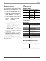
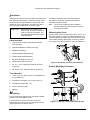
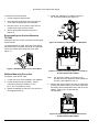
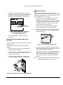
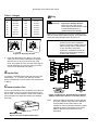
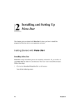
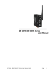
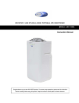
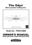
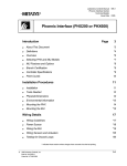
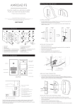
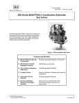
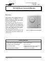
European Electronic Controls Catalog Catalog Section Product Bulletin Issue Date A TE-7000 1198 TE-7000 Room Command Module I ntroduction The TE-7000 Room Command Module is designed for use with the VMA1400 series VAV Modular Assembly. The VMA1400 is a control device for a variable air volume (VAV) terminal unit that provides conditioned air to the room in which the TE-7000 is installed. The module has an NTC temperature sensor, a dial for setpoint adjustment within the range of 12 to 28°C or -3 to +3K, and an occupancy button with an LED indicator. If the VAV controller is not already in occupied mode, as shown by the LED indicator, the occupant may press the occupancy button to obtain comfort control for a set period of time, normally defaulted to one hour. The module also has a built-in connector for a PC with the software to test and commission the VMA1400 series VAV Modular Assembly and the air supply system. Figure 1: TE-7000 Room Command Module Features and Benefits q Modern attractive cover, in white or off-white, which snaps onto a plug-in mounting base. Blends with room décor. Easy to install and service. q Terminals located on mounting base. Easy to wire and test. q Service tool connection. Variable Air Volume system can be commissioned and balanced at the room module location. q Range of standard mounting kits. Flexibility in mounting possibilities. © 1998 Johnson Controls, Inc. Order No. DS 24.130 E A5.1 2 TE-7000 A pplication Overview O rdering Codes The TE-7000 Room Command Module is used specifically with the VMA1400 series VAV Modular Assembly and includes: European Models • an NTC “K2” temperature sensor (see the NTC K2 Resistance Table on page 10) • a setpoint dial and potentiometer for remote setpoint adjustment of 12 to 28°C or -3 to +3K • an LED to indicate the occupancy mode as follows: • steady on: occupied (comfort) mode blinking: standby mode off: unoccupied (or off) mode an occupancy button (switch) in a series circuit with an LED to either: 1. command the occupied mode from the standby or unoccupied mode for a set period of time, or 2. change the occupancy mode to occupied, standby or unoccupied for a set period of time, as defined in the configuration data base of the VMA device. • a socket for the connection of a PC with testing and commissioning software via an RS485/RS232 converter. A cable is available for use with the IU-9100 converter (see ordering codes). The Room Command Module is connected by an 8-wire cable to the VMA and requires no other source of power. (With System 91 Type Service Tool Connector) Ordering Code Color Setpoint Dial Range TE-7000-8002 Off-White/ Gray Base White/ White Base Off-White/ Gray Base White/ White Base 12 to 28 °C TE-7000-8002-W TE-7000-8003 TE-7000-8003-W 12 to 28 °C -3 to +3 K -3 to +3 K Note: Add “-K” to code for setpoint dial with serrated edge, e.g. TE-7000-8002-K, TE-7000-8002-WK Accessories Ordering Code Description TE-7000-8900 Service Tool Connector Cable (1.5m) (for use with IU-9100 converter) Special Tool (to open module) Dial-Stop Screws Kit (bag of 100 self-tapping screws) Serrated Knob Kit (bag of 10 knobs) - Off-white Serrated Knob Kit (bag of 10 knobs) - White Surface Mounting Kit - Gray Surface Mounting Kit - Off-white Surface Mounting Kit - White Wall Box Mounting Kit - White Panel Mounting Kit - White TM-9100-8900 TM-9100-8901 TM-9100-8902 TM-9100-8902-W TM-9100-8930 TM-9100-8931 TM-9100-8931-W TM-9100-8941-W TM-9100-8951-W For information purposes only: North American Models from Customer Service in Milwaukee (all in off-white with gray USA wall plate accessory, serrated knob and telephone jack Service Tool connector) A5.1 Ordering Code Setpoint Dial Range TE-7000-0001 TE-7000-0002 TE-7000-0003 65 to 85 °F 12 to 28 °C - to + (no units) TE-7000 3 M ounting and Wiring Instructions The TE-7000 module is designed for wall mounting in the room to be controlled, using at least two of the four screw holes on the base. The module may be mounted directly on the wall, or one of the three mounting kits may be used. The wiring enters from the back through the base. Choose an appropriate place where the temperature is representative of the general room conditions. Avoid cold or warm draughts from doors or windows, and exposure to radiant heat from lamps, radiators or direct sunlight. However, sufficient air circulation over the module is required for a satisfactory response to room temperature changes. Place insulation material in the wiring conduit or any open space behind the wall to prevent air entering the module through the base. The TM-9100-8941-W Wall Box Mounting Kit • Adjust height “D” turning screws “A” to match the depth of the wall box. Max. Ø 62 mm Min. Ø 55 mm Min. 45 mm • Insert the kit into the wall box in the position shown below. Remove the base from the cover by inserting the point of the special tool (TM-9100-8900) into the small hole at the center top of the cover. While pressing down gently, prise the base away from the cover. As the two parts separate, remove the tool and continue to pull the cover away from the base until the cover is free. To reassemble the module, place the cover over the lower edge of the base and push the upper part of the cover until it “clicks” firmly in place. The TM-9100-893x(-W) Surface Mounting Kit Screw the kit directly on the wall using holes “A” and mount the base of the module on the kit, using the two screws included and inserting them in the two opposite holes “B”, as indicated below: UP OB EN • Tighten screws “B” until the prongs clamp properly on the box. • Mount the base of the module on the kit as shown below, using the two screws included and inserting them in two opposite holes of the four marked “C”. A B A5.1 4 TE-7000 The TM-9100-8951-W Panel Mounting Kit • Cut a circular hole in the panel with a diameter dimension as shown below: Max. Ø 60 mm Min. Ø 57 mm Max. 12 mm • Turn prongs “A” as shown below. Insert the kit into the panel in the position shown below. Wiring Instructions The installation of electrical wiring must conform to local codes and should be carried out by authorized personnel only. Users should ensure that all Johnson Controls products are used safely and without risk to health or property. Before connecting or disconnecting any wires, ensure that all power supplies have been switched off and all wires are potential free to prevent equipment damage and electrical shock. Terminations are made on the terminal blocks in the base of the module which accept 1.5 mm2 (16 AWG) wires. All wiring to the module is at extra low (safe voltage) and must be separated from power line voltage wiring. Do not run wiring close to transformers or high frequency generating equipment. Complete and verify all wiring connections before applying power to the VMA1400 to which the module is connected. Do not attempt field repairs. If the module does not operate properly when correctly wired, it should be replaced. • Turn prongs “A” as shown below. Turn screws “B” until the kit is fixed on the panel. • Mount the base of the module on the kit as shown below, using the two screws included and inserting them in two opposite holes of the four marked “C”. A5.1 Figure 2: Wiring Diagram TE-7000 D 5 ial-Stop Screws A pair of self-tapping screws can be installed to mechanically limit the range of the TM-9100 set point dial between ±3 K and ±0.3 K or between 12/28°C and 19.3/20.7°C. 4. To limit travel of the dial, choose the desired range, and insert screws in the corresponding holes. For example, for a limitation of ± 2.5 K, insert one screw each in the holes marked (A) in Figure 4. 1. Remove the base of the module from the cover by inserting the point of the special tool (TM-9100-8900) into the small hole at the center top of the cover. While pressing down gently, prise the base away from the cover. As the two parts separate, remove the tool and continue to pull the cover away from the base until the cover is free. 2. Set the dial to the center top position, with the pointer (indentation) at the 0 K or 20°C mark. 3. Then insert the special TM tool (Ordering Code TM-9100-8900) through the hole in the back of the cover (1) and push gently until the dial knob becomes free (2). 2 1 tmtbhole Note: For an asymmetrical range, you may insert screws into differently lettered holes on each side. A B C D E F G 12-28°C ±3K 13.3 / 26.7 14.3 / 25.7 15.3 / 24.7 ± 2.5 ± 2.1 ± 1.8 16.3 / 23.7 17.3 / 22.7 18.3 / 21.7 ± 1.4 ±1 ± 0.7 19.3 / 20.7 ± 0.3 tmtbremd Figure 3: Removing the Dial Knob 3. On the front of the module cover you will see a series of seven holes on either side of the set point dial pivot, which had been hidden by the knob. G F G F E E D D C 5. Press the dial knob back in place on the cover, making sure the pointer (indentation) is aligned with the 0 K or 20°C mark at the top of the circle. Then place the cover over the lower edge of the TM-9100 base and push the upper part of the cover until it “clicks” firmly into place. C B A B A Figure 4: Dial-Stop Screws A5.1 6 TE-7000 S errated Dial Knob S ervice Tool Socket To replace a smooth dial knob with a serrated knob, follow steps 1, 2, 3 and 5 under Dial-Stop Screws, substituting a serrated knob for the smooth knob in Step 5. The service tool socket is accessed by sliding the panel upwards as shown in Figure 6 below. Sliding panel Service Tool Socket set esc Figure 6: Service Tool Socket Figure 5: Module with Serrated Dial Knob A5.1 TE-7000 7 D imensions (in mm.) 80 Ø 4.2 33 TB1 1 2 3 4 20 24 16 Setpoint adjustment TB2 5 6 7 8 60 UP Ø 4.2 80 12 6.2 ModeLED 28 °C 6.2 Mode selector 4.2 4.2 60 Figure 7: Basic Model TE-7000-800x Figure 8: Plug-in Mounting Base Max. Ø 60 mm Min. Ø 57 mm 78 12 78 78 78 12 Figure 9: Wall Box Mounting Kit TM-9100-8941-W Figure 10: Panel Mounting Kit TM9100-8951-W UP OB EN 58 60 Ø5 78 Ø 3.5 25 78 11 17 13 20 Figure 11: Surface Mounting Kit TM-9100-893x(-W) A5.1 8 TE-7000 NTC K2 Resistance Table Temperature in °C 0 5 10 15 20 25 30 35 40 Resistance in Ω 7352,8 5717,8 4481,5 3537,9 2812,8 2252,0 1814,4 1470,6 1199,6 S pecifications Supply Voltage Power from VMA1400 VAV Modular Assembly Ambient Operating 0 to 50 °C Conditions 10 to 90% RH noncondensing Ambient Storage -20 to 70 °C Conditions 10 to 90% RH noncondensing Terminations Terminal block in base for 1 x 1.5mm ² (16 AWG) (maximum) cable Temperature Sensor NTC Thermistor 0 to 40 °C, 2252 Ω at 25 °C Remote Set Point 2.0 KΩ potentiometer (with 4.99 KΩ parallel resistor) marked for 12 to 28 °C or -3 to +3 K. Mechanical limitation of travel available with dial-stop screws. (See ordering codes.) Occupancy Button and Momentary contact and LED in series circuit. Mode Indicator Mounting Direct surface mount, plastic base for surface mount with wiring conduit, and recessed wall box and panel mounting kits. (See ordering codes.) Housing Material: ABS + polycarbonate, self extinguishing VO UL94 Protection: IP30 (IEC529) Dimensions (HxWxD) 80 x 80 x 33 mm Shipping Weight 0.15 kg Agency Compliance CE Directive 89 / 336 / EEC EN50081-1, EN 50082-1 The performance specifications are nominal and conform to acceptable industry standards. For application at conditions beyond these specifications, consult the local Johnson Controls office. Johnson Controls, Inc. shall not be liable for damages resulting from misapplication or misuse of its products. Johnson Controls International Westendhof 8 45143 Essen Germany A5.1 Rev. Level 1198 European Electronic Controls Catalog Printed in Germany FANs 216, 1628.3 Product/Technical Bulletin Issue Date TE-7000 1298 TE-7000 Series Room Command Module The TE-7000 Room Command Module is designed for use with the VMA1400 Series VAV Modular Assembly, a control device for a Variable Air Volume (VAV) terminal unit that provides conditioned air to the space in which the TE-7000 is installed. The module has an NTC (Negative Temperature Coefficient) temperature sensor, a dial for setpoint adjustment within the range of 55 to 85°F, 12 to 28°C, or ±5°F, and a Temporary Occupancy button with a Light-Emitting Diode (LED) indicator. If the VMA controller is not already in occupied mode, as shown by the LED indicator, the occupant may press the Temporary Occupancy button to request comfort control for a set period of time. The TE-7000 also has a 6-pin communication port to connect a Personal Computer (PC). The PC software is used to test, balance, and commission the VMA1400 Figure 1: TE-7000 Series Room Command Module Shown with Fahrenheit and Celsius Setpoint Dials Series VAV Modular Assembly. Features and Benefits q High Accuracy Thermistor q q q q q q q Sensor Choice of Setpoint Dials Adjustable Rotation Stops Temporary Occupancy Button External LED Mode Indicator Snap-in, Plug-in Terminals Located on Mounting Base Choice of Wallbox Mounting Base (included with all models) 6-pin Communication Port © 1998 Johnson Controls, Inc. Part No. 24-85638-1028, Rev. — Code No. LIT-216335 Provides a low-cost alternative to expensive alloy sensors Provides aesthetic flexibility Provide limits to user setpoint adjustment range Enables the user to adjust room comfort by selecting the controller’s operation mode Shows the controller’s current operation mode Provides easy wiring and testing Makes the TE-7000 adaptable for most installations Allows commissioning and balancing of VAV system at the room module location 1 www.johnsoncontrols.com Preliminary—This material will change. Preliminary—This material will change. P roduct Overview D imensions The TE-7000 Room Command Module is used specifically with the VMA1400 Series VAV Modular Assembly, and is not compatible with TE-6400 Metastat applications. The TE-7000-0001 and TE-7000-0002 provide remote adjustment of the setpoint of the controller, while the TE-7000-0003 model provides remote offset adjustment (change to the room temperature setpoint programmed into the controller). The LED, located directly above the Temporary Occupancy button on the TE-7000, indicates the current operating mode of the VMA1400 as follows: • LED on: Occupied mode (Comfort) • LED off: Unoccupied mode (Night) • LED flashing: Standby mode Figure 2: TE-7000 Cover Dimensions (in./mm) The TE-7000 Temporary Occupancy button provides a means to circumvent day/night programming and turn the HVAC system on or off manually. If pressed for more than a second, the controller mode is changed. Figure 3: TE-7000 Base Dimensions (in./mm) Figure 4: TE-7000 Wallplate Dimensions (in./mm) 2 TE-7000 Series Room Command Module Product/Technical Bulletin Preliminary—This material will change. I nstallation Install the TE-7000 where the occupant can easily read and adjust the setpoint dial. Locate the module where the temperature is representative of the general room conditions. Avoid mounting the TE-7000 near cold or warm air drafts, radiant heat, or direct sunlight. IMPORTANT: Do not mount the module on an exterior wall. All wiring connections must be made in accordance with the National Electrical Code and all local regulations. Parts Included • room command module with attached surface mounting base • separate wallplate for wallbox mounting • wallplate endcaps (2) • serrated setpoint dial (attached) • smooth setpoint dial (separate) • dial-stop self-tapping screws (2) • hollow plastic wall anchors (2) • No. 8 x 1 1/4 in. slotted pan-head sheet metal screws (2) • No. 6-32 x 1/2 in. flat-head machine screws (2) For wallbox mounting, follow the instructions for removing the cover and proceed to the Wallbox Mounting Procedure section. Note: All TE-7000 models include the Wallbox Mounting Base Kit. Discard the kit if surface mounting the module. Removing the Cover To remove the cover from the base, insert a 1/16 in. (1.5 mm) Allen wrench or T-4000-119 Stat Adjustment Tool into the small hole located in the center of the top of the cover. While pressing down gently on the tool, pull the cover away from the base until it is free. (See Figure 5.) Figure 5: Removing the Cover from the Base Surface Mounting Procedure Tools Needed • 1/16 in. (1.5 mm) Allen wrench or stat adjustment tool (T-4000-119) • screwdrivers, flat-blade, 1/4 in. and 3/16 in. tip • screwdriver, Phillips, No. 1 tip • 5/16 in. drill bit and drill • hammer M ounting The TE-7000 series allows for two mounting methods: surface mount and wallbox mount. For instructions on surface mounting, follow the instructions for removing the cover and proceed to the Surface Mounting Procedure section. Figure 6: Installing a Surface Mounted TE-7000 TE-7000 Series Room Command Module Product/Technical Bulletin 3 Preliminary—This material will change. To surface mount the TE-7000: 1. Pull the wiring through the wall. 2. Place the base against the wall, and mark the screw holes using the base as a template. 3. Drill two 5/16 in. (8 mm) holes, insert anchors, position base, then drive the screws. 4. Wire to appropriate terminals as shown in Figure 16. 4. Fasten the wallplate to the wallbox using the No. 6 screws provided. (See Figure 8.) Reassembling the Surface Mounted TE-7000 If using the dial-stop screws, proceed to the Dial-Stop Screws section. Figure 8: Installing a TE-7000 Using a Wallplate To reassemble the TE-7000, place the cover against the bottom edge of the base, and push the upper part of the cover until it clicks firmly into place. (See Figure 7.) Figure 7: Reattaching the Cover to the Base Wallbox Mounting Procedure To wallbox mount the TE-7000: 1. Loosen the cover screw installed in the wallplate. 2. Pull the wiring through the wallbox. (These instructions assume a standard 2 x 4 in. [51 x 102 mm] wallbox is used.) 3. Rotate the wallplate so that one of the arrows on the wallplate points up. Figure 9: Terminal Locations Shown on Inside of TE-7000 Surface Mount Base Note: 5. The terminal locations on the back of the TE-7000 cover are opposite of those marked on the base. (See Figures 9 and 11.) Remove the terminal blocks from the TE-7000 base by lifting the plastic fingers on the back of the base and sliding each terminal block down and out of the retainer. (See Figure 10.) Discard this TE-7000 base. Figure 10: Removing the Terminal Blocks from TE-7000 Surface Mount Base 4 TE-7000 Series Room Command Module Product/Technical Bulletin Preliminary—This material will change. 6. Push the terminal blocks onto the pins located inside the TE-7000 cover with screw heads toward the board and the wire leads exiting terminal blocks from the bottom as shown in Figure 11. ial-Stop Screws D A pair of self-tapping screws can be installed to mechanically limit the range of the TE-7000 setpoint dial between ±5°F and ±0.4°F or between 55 and 85F° (12 to 28C°), and 68 to 71F° (19 to 21C°). 1. Remove the base of the module from the cover by inserting a 1/16 in. (1.5 mm) Allen wrench or T-4000-119 Stat Adjustment Tool into the small hole located in the center of the top of the cover. While pressing down gently on the tool, pull the cover away from the base until it is free. 2. Set the dial to the center top position, with the pointer (indentation) at the 70°F (20°C) mark. 3. Insert the Stat Adjustment Tool through the hole in the back of the cover (1) and push gently until the dial knob is free (2). Figure 11: Inside View of TE-7000 Cover with Terminal Blocks Positioned for Wallplate Mounting 7. Wire to appropriate terminals as shown in Figure 16. Reassembling the Wallbox Mounted TE-7000 If using the dial-stop screws, proceed to the Dial-Stop Screws section. To replace the TE-7000 cover onto the installed wallplate: 1. Place the bottom edge of the cover against the bottom edge of the wallplate. 2. Rotate the cover up onto the wallplate, and tighten the cover screw using the stat tool or Allen wrench. (See Figure 12.) 3. Install the endcaps provided by snapping them onto the wallplate. (See Figure 1, left picture.) Figure 13: Removing the Setpoint Dial 4. On the front of the module cover there is a series of seven holes on either side of the setpoint dial pivot, which had been hidden by the knob. To limit travel of the dial, choose the desired range, and insert screws in the corresponding holes. (See Table 1.) For example, for a limitation of ±4.2F°, insert one screw each in the holes marked (A) in Figure 14. Note: For an asymmetrical range, insert screws into differently lettered holes on each side. Figure 12: Reattaching the Cover to the Wallplate TE-7000 Series Room Command Module Product/Technical Bulletin 5 Preliminary—This material will change. Table 1: Ranges Holes 55-85°F ±5° F 12-28°C A 57.5/82.5 ±4.2 13.3/26.7 B 59.3/80.7 ±3.6 14.3/25.7 C 61.2/78.8 ±3 15.3/24.7 D 63/77 ±2.3 16.3/23.7 E 65/75 ±1.7 17.3/22.7 F 66.8/73.2 ±1 18.3/21.7 G 68.6/71.4 ±0.4 19.3/20.7 W iring ! CAUTION: Make wiring connections to the terminal blocks in the base of the TE-7000 module using No. 24-16 AWG wire. Follow the wiring diagram shown in Figure 16. IMPORTANT: Figure 14: Dial-stop Screws 5. Equipment Damage Hazard. Disconnect the power supply before wiring connections are made to avoid electrical shock or possible equipment damage. All wiring to the module is low voltage (Class 2) and must be separated from the power line voltage wiring. Do not run wiring close to transformers or high frequency generating equipment. Complete and verify all wiring connections before applying power to the controller. Press the dial knob back in place on the cover, making sure the pointer (indentation) is aligned with the 70°F (or 20°C) mark at the top of the circle. Then place the cover over the lower edge of the TE-7000 base and push the upper part of the cover until it clicks firmly into place. S etpoint Dial To replace a serrated setpoint dial with a smooth dial, follow Steps 1, 2, 3, and 5 in the Dial-Stop Screws section, substituting a smooth dial for the serrated dial in Step 5. C ommunication Port A 6-pin communication port is located on the bottom of the TE-7000 to connect a Personal Computer (PC) to the TE-7000. The PC software is used to test, balance, and commission the VMA1400 Series VAV Modular Assembly. Figure 16: Wiring to a TE-7000 Room Command Module with an NTC Sensor or Remote Sensor Note: Check the VMA configuration to verify that the 55 to 85°F setpoint range has been defined to accommodate the TE-7000. Refer to the Variable Air Volume Modular Assembly (VMA) Application Note (LIT-6375125) in the HVAC PRO for Windows User Manual for more information. Figure 15: 6-pin Communication Port 6 TE-7000 Series Room Command Module Product/Technical Bulletin Preliminary—This material will change. R eplacement and Repair Table 2: Nominal Temperature vs. Resistance for Thermistor Sensor Temperature Resistance (ohms) Field repairs must not be made. To order a replacement, refer to the Ordering Information section for the desired product code number, and contact your Johnson Control representative. °F °C Thermistor 30 -1 7784 40 4 5880 O rdering Information 50 10 4484 Table 3: Room Command Modules 60 16 3450 70 21 2678 80 27 2095 90 32 1652 100 38 1313 110 43 1051 Ordering Code Setpoint Scale TE-7000-0001 55 to 85°F TE-7000-0002 12 to 28°C TE-7000-0003 - to + (no units) Table 4: Replacement Parts and Accessories Ordering Code Description TE-6400-603 End Caps (2) TM-9100-8901 Dial-Stop Screws Kit (bag of 100 self-tapping screws) TM-9100-8902 Serrated Knob Kit (bag of 10 knobs) T-4000-119 Stat Adjustment Tool (to open module) ACC-INSL-0 Wallbox Mounting Pad (bag of 10) ACC-INSL-1 Surface Mounting Pad (bag of 10) Figure 17: Temperature vs. Resistance for Thermistor Sensor TE-7000 Series Room Command Module Product/Technical Bulletin 7 Preliminary—This material will change. S pecifications Product Supply Voltage Ambient Operating Conditions Ambient Storage Conditions Terminations Thermistor Sensor Setpoint Temporary Occupancy Button Mode Indicator Mounting Housing Dimensions (H x W x D) Shipping Weight Agency Compliance TE-7000 Series Room Command Module Power from VMA1400 VAV Modular Assembly 32 to 122°F (0 to 50°C); 10 to 90% RH non-condensing -4 to 158°F (-20 to 70°C); 100% RH non-condensing Terminal block accommodates 24 to 16 AWG (maximum) wire. Temperature Coefficient: Nonlinear, negative temperature coefficient Reference Resistance: 2.25k ohms at 77°F (25°C) Accuracy: ±0.36°F (±0.2°C) in the range of 32 to 158°F (0 to 70°C) 2k ohm potentiometer (with 4.99k ohm parallel resistor) Momentary contact Red LED Direct surface mount or 2 x 4 in. (51 x 102 mm) wallbox mounting base Material: Protection: Flame resistant thermoplastic, self-extinguishing UL94 VO NEMA 1, IP 30 (IEC529) 3.2 x 3.2 x 1.3 in. (80 x 80 x 33 mm) 0.33 lb (0.15 kg) CE Directive 89/336/EEC EN 50081-1, EN 50082-2 The performance specifications are nominal and conform to acceptable industry standards. For application at conditions beyond these specifications, consult the local Johnson Controls office. Johnson Controls, Inc. shall not be liable for damages resulting from misapplication or misuse of its products. Controls Group 507 E. Michigan Street P.O. Box 423 Milwaukee, WI 53201 8 TE-7000 Series Room Command Module Product/Technical Bulletin www.johnsoncontrols.com INSTALLATION INSTRUCTIONS INSTALLING TE-7000 ROOM COMMAND MODULE MOUNTING 1. Remove the base of the module from the cover by inserting a pointed tool (a special tool, Ordering Code TM-9100-8900, is available from Johnson Controls) into the small hole at the center top of the cover (See Figure 1). 2. While pressing down gently, prise the base away from the cover. 3. As the two parts separate, remove the tool and continue to pull the cover away from the base until the cover is in free . Figure 1 4. Mount the base on the wall to cover the electrical output and secure with at least two screws. - Built-in NTC Temperature Sensor TE-7000-800X 2 = Set point 12 - 28 °C 3 = Set point + / - 3K - Push botton Mode Selector with Led indication: - Comfort / Led On - Stand-by / Led blinking - Night / Led Off TE-7000-000X 1 = Set point 55 - 85 °F 2 = Set point 12 - 28 °C 3 = Set point – 0 + Set point override range: 55-85 °C ±3K On request : concealed pot for set point override - Wiring Connections TB1 - - 1 2 TB2 3 4 5 AI-COM BI-1 AI-2 AI-1 6 7 - - +15V ZBZB+ 8 COM P/N 24-85638-897 Rev.A