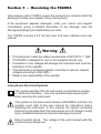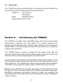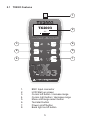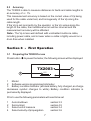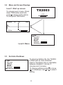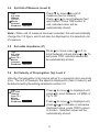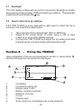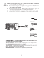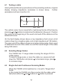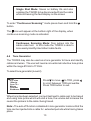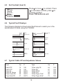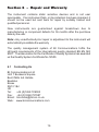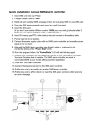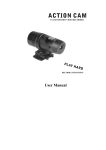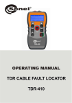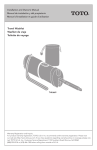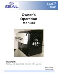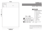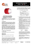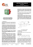
1
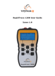
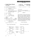
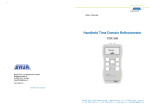
TX
2003
TDR Cable Fault Locator
Operating Instructions
BI
Communications
Innovation through Technology
4403407 issue 1
CONTENTS
Section 1
Receiving the TX2003
1.1
Safety notices.................................................3
1.2
Standards.......................................................4
Section 2
Introducing the TX2003
2.1
TX2003 features.............................................5
2.2
Specifications .................................................6
2.3
Accuracy ........................................................7
Section 3
First operations
3.1
Preparing the TX2003 ....................................7
3.2
Menu & screen displays .................................8
3.3
Set auto shutdown .........................................8
3.4
Set unit of measure ........................................9
3.5
Set cable impedance......................................9
3.6
Set Velocity of propergation ...........................9
3.7
Backlight.......................................................10
3.8
How to determine unknown Vp Settings ......10
Section 4
Using the TX2003
4.1
Testing a cable .............................................12
4.2
Selecting range scales .................................12
4.3
Single shot and Continuous scan mode ......12
4.4
Tone generator .............................................13
4.5
Adjusting contrast.........................................14
4.6
Typical fault displays ....................................14
4.7
Typical Cable Vp & Impedance values.........14
Section 5
Maintenance
5.1
Battery replacement .....................................15
5.2
Cleaning .......................................................15
5.3
Storage.........................................................15
Section 6
Warranty & Repair
6.1
Contacting us ...............................................16
2
Section 1 - Receiving the TX2003
Upon delivery of the TX2003, ensure the contents are consistent with the
packing list, notify your supplier of any missing items.
If the equipment appears damaged, notify your carrier and supplier
immediately, giving a detailed description of any damage, save the
damaged packaging to substantiate your claim.
The TX2003 includes a 0.5 mtr test lead, soft case, batteries and user
manual.
Warning
? This instrument meets the safety requirements of IEC61010-1: 1995
? TheTX2003 is designed for use on de-energized circuits only.
? Connection to line voltages will damage the instrument and could be
hazardous to the operator
? This instrument is protected against connection to telecom network
voltages according to EN61326-1.
? Safety is the responsibility of the operator
International Electrical Symbols
This symbol signifies that the instrument is protected by double
or reinforced insulation. Use only specified replacement parts
when servicing the instrument.
This symbol on the instrument indicates a WARNING, and that the
operator must refer to the user manual for instructions before
operating the instrument. In this manual, the symbol preceding
instructions indicates that if the instructions are not followed, bodily
injury, installation/sample and product damage may result.
Risk of electric shock. The voltage of the parts marked with this
symbol may be dangerous.
3
1.2
Standards
The TX2003 has been manufactured in accordance with and meets the
requirements of the following international standards:
SAFETY
IEC 61010-1
EN 60950
EMC
BS/EN 61326-1
Water/Dust Proof to IP54
Section 2 - Introducing the TX2003
The TX2003 is a 6,000 meter (19,000ft) range, hand held, time domain
reflectometer weighing only 350 grams (12 ounces) designed for
identifying and locating faults on Metalic power, Data and Communication
cables, with a 7 mtr first range scale and 0.5 mtr dead zone, is ideal for
locating near end faults.
The TX2003 injects a series of pulses into the cable under test, the
velocity at which the pulses travel is determined by the type of cable, this
is known as the velocity of propergation (Vp) of the cable.
The Vp value is expressed as a percentage of the speed of light i.e. 67%
or ft/mtrs/micro second (ms), this value will vary according to the type of
cable under test. The TX2003 can accept user selectable values between
1 and 99% (or the equivalent value in feet or meters per micro second).
Based on the selected Vp and the time taken for the pulses to travel
through the cable, a reflection profile of the cable under test is displayed,
identifying impedance anomalies along the cable. By aligning the
moveable cursor to the selected anomaly the distance to fault is displayed
in feet or meters.
4
2.1
TX2003 Features
1
TX2003
2
V1.0
3
4
6
5
8
7
1.
2.
3.
4.
5.
6.
7.
8.
BNC Input connector
LCD Start up screen
Cursor left button / increase range
Cursor right button / decrease range
Menu and range select button
Test start button
Power on/off button
Back light on/off button
5
2.2
Specifications
Ranges Meters
Feet
Range Selection
Accuracy
Resolution
Sensitivity
Velocity Factor
Output Pulse
Output Impedance
Output Pulse Width
Scan Rate
Tone Generator
Battery Life
Power Supply
Power Down
Back Lit Display
Voltage Protection
Operating Temp
Storage Temp
Dimensions
Weight
Safety
EMC
Water/Dust Proof
7, 15, 30, 60, 120, 250, 500, 1km, 2km, 3km, 6km
23, 49, 98, 197, 394, 820, 1640, 3280, 6560,
9850, 19000
Manual range control
1% of selected range*
Approx 1% of range
Min 3 pixel return at 4km on 0.6mm Ø, PE, TP
Adjustable from 1% to 99%
5 volts peak to peak. Into open circuit
Selectable 25, 50, 75 & 100 ohms
3 ns to 3 ms, Automatic with range
2 scans / second or scan held
810 – 1100Hz
60 hours continuous scanning
6 volts 4 x 1.5 AAAlkaline cells
Selectable 1, 2, 3, 5 minutes or disabled
128 x 64 pixel
250 volts AC
-10º / 50ºC
-20º / 70ºC
165 x 90 x 37 (6.5 x 3.5 x 1.5 ins)
350 gms (12oz)
IEC 61010-1
EN 60950
BS/EN 61326-1
IP54
* Measurement accuracy of <+/- 1% assumes the instrument setting for
velocity of propergation (Vp) of the cable under test to be accurately set,
homogeneity of the Vp along the cable length, and accurate cursor
positioning.
6
2.3 Accuracy
The TX2003 is able to measure distances to faults and cable lengths to
an accuracy of +/- 1%.
This measurement accuracy is based on the correct value of Vp being
used for the cable under test, and homogeneity of the Vp along the
cable length.
If the Vp is set incorrectly by the operator, or the Vp varies along the
length of the cable, then additional errors will be incurred and the
measurement accuracy will be affected.
Note:- The Vp is less well defined with unshielded multicore cable,
including power cable, and is lower when a cable is tightly wound on a
drum than when installed.
Section 3 - First Operation
3.1
Preparing the TX2003 for use
Press button
to power the tester, the following screen will be displayed:
TX2003
2
1
V1.0
3
1 Model
2 Software version programmed into tester
3 Battery condition indicator (all black battery, fully charged, as charge
decreases symbol changes to white) Battery condition indicator is
permanently displayed.
Prior to use the following parameters will need to be set
1
2
3
4
Auto shutdown
Set contrast
Select unit of measure
Select velocity of propergation
section 3.3
section 4.5
section 3.4
section 3.6
7
3.2
Menu and Screen Displays
Level 1. Start up screen
TX2003
To access level 2 menu. Press
down TDR button and hold,
press release both buttons.
To exit press TDR button.
100m/us
T/P
100W
V1.0
60m
25.0m
TDR
V/2 m/us
100m/us
T/P 100 W
Metres
Contrast
Shutdown: Disabled
Level 2. Menu
3.3
Set Auto Shutdown
TDR
V/2 m/us
100m/us
T/P 100 W
Metres
Contrast
Shutdown: 2minutes
To preserve battery life, the TX2003
is fitted with an auto shutdown
feature. Shutdown time is selectable
between disabled 1 minute, 2
minutes and 3 minutes.
To change settings press to move
to shutdown, use or to select
setting.
8
3.4
Set Unit of Measure (Level 2)
TDR
V/2 m/us
100m/us
T/P 100 W
Metres
Contrast
Shutdown: 2minutes
Press to move to unit of
measure (feet or meters).
Press or to scroll between feet
and meters. Press TDR button to
exit, selected value will be
automatically stored.
Note:- When unit of measure has been selected, this will automatically
change the V/2 figure, which will also be displayed in the selected unit
of measure.
3.5
Set cable Impedance (Z)
TDR
V/2 m/us
100m/us
Coax 75 W
Metres
Contrast
Shutdown: 2minutes
3.6
Press to move cursor to Z, to
scroll between values press or To
exit press TDR, selected values will
be automatically stored.
Set Velocity of Propergation (Vp) Level 2
Velocity of propergation (Vp) may be set as % or speed in micro seconds
(ms). The unit of measure, the speed is displayed in (feet or meters), will
be determined by the setting selected in section 3.4
TDR
V/2 m/us
100m/us
Coax 75 W
Metres
Contrast
Shutdown: 2minutes
Press to move to displayed unit,
press to scroll between v/2 M/Ms or
Vp % UC.
Press to move to displayed unit,
press or to increase or decrease
displayed value, press TDR to return
to screen. Selected values will be
automatically stored.
9
3.7
Backlight
The LCD display is fitted with an electro-luminescent backlight to enable
easy viewing under a variety of different lighting conditions. The backlight
is switched on and off with the key.
3.8
How to determine Vp settings
If the TDR TX2003 is to be used with a cable type for which the Vp is
unknown, this must first be determined.
1.
2.
Take a sample of the cable at least 100m or 300ft long.
Measure the actual length of cable using a rule or tape
measure, or some other reliable method.
Connect the TDR TX2003 and adjust the Vp setting such that
the tester gives a correct reading of the sample length.
3.
Section 4
-
Using the TX2003
Upon completion of the set up procedures in section 3, press button
and the following test screen will be displayed
2
1
Vp=67%
Coax 75 W
7m
3
6
7
5
1.
2.
3.
4.
5.
6.
7.
8.
8
0.4m
Vp Setting
Impedance setting (Z)
Range scale 7 mtrs
Battery condition indicator
Distance of cursor
Cursor
Output pulse
Scan mode icon (indicating scan mode selected)
10
4
Attach the test lead set to the TX2003 via the BNC connector
located at the top of the unit,
1. Ensure that no power supply or equipment is attached to
the cable to be tested
2. Ensure that the far end of the cable under test is open or
shorted (not fitted with a resistive termination)
3. Attach the TX2003 to one end of the cable to be tested
Coaxial Cable
Shielded Cable
Vp=67%
0.4m
Coax 75 W
Twisted Pair
7m
Multi-conductor Cable
Coaxial Cable: Connect the red clip to the centre wire and
the black clip to the shield/screen.
Shielded Cable: Connect the red clip to a wire adjacent to
the shield and the black clip to the shield.
Twisted Pair: Separate out one pair and connect the red and
black clips to the two wires of the pair.
Multicore Cable: Connect the clips to any two wires.
11
4.1
Testing a cable
Having followed the set up procedures in the preceding sections, a typical
display showing impedance anomalies is shown below. Further
examples are shown in section 4.6.
Vp=72% Z=100Ω
64m
129m
180m
The vertical cursor line is moved left or right along the line of the trace by
pressing and buttons to determine the distance to the event. Position
the cursor at the beginning of the event and read off the distance at the
bottom left corner.
On the fault display shown above a low impedance fault occurs at 64
meters shown by a negative spike, and a high impedance at 129 meters.
The open end of the cable is shown as a large positive spike, this is used
to determine the end of the cable run and the overall length of the cable
being 180 meters.
4.2
Selecting Range Scales
The TX2003 has 11 range scales covering the range of 0.5 to
6,000 meters.
To select a range scale, or scan the cable run, press and hold
down the TDR button and press
to decrease range, press
to increase range.
4.3
Single shot and Continuous Scanning Modes
When the TX2003 is first switched on, it is set to “Single Shot”
mode.
In this mode the TX2003 only fires a pulse into the cable under
test when either the and buttons or button is pressed.
12
Single Shot Mode: Saves on battery life and also
enables the TX2003 to be disconnected from the cable
while still leaving the fault display on the screen
To enter “Continuous Scanning” mode press down and hold the
button.
The icon will appear at the bottom right of the display, when
continuous scanning mode is activated.
Continuous Scanning Mode: fires pulses into the
cable under test. In this mode the TX2003 is able to
more easily identify intermittent cable faults.
4.4
Tone Generator
The TX2003 may also be used as a tone generator to trace and identify
cables and wires. The user will need a conventional inductive tone probe
within the range 810 Hz to 1110Hz.
To select tone generator (Level 2)
TDR
V/2 m/us
100m/us
Coax 75 W
Metres
Contrast
Shutdown: 2minutes
Press to move
to TDR, press
to scroll between TDR and warble.
Press TDR button to exit.
When tone has been selected, connect test lead to cable pair to be traced
and using tone probe which will emit a tone, the volume will increase the
nearer the probe is to the cable / being traced.
Note:- The auto off function is disabled in tone generator mode so that the
tone can be injected into a cable for extended periods while tracing takes
place.
13
4.5
Set Contrast (level 2)
Press to move to contrast. Press
to decrease contrast, press to
increase contrast.
Press TDR button to exit.
TDR
V/2 m/us
100m/us
Coax 75 W
Metres
Contrast
Shutdown: 2minutes
4.6
Typical Fault Displays
The following diagrams show typical fault traces to assist you in the
identification of faults using the TX2003:
4.7
OPEN
CONDUCTOR
WET SPLICE/
WATER
SHORTED
CONDUCTOR
FRAYED
CABLE
SPLICE
WATER
INGRESS
BRIDGE TAP
TAP
SPLIT/
RESPLIT
SPLITTER
Typical Cable V.P and Impedance Values
Type
Vp
Z
Type
Vp
Z
Cat5 STP
Cat5 UTP
Coax Air
Coax Air Space
Coax Foam PE
Coax Solid PE
72
70
98
94
82
67
100
100
50/75
50/75
50/75
50/75
T/Pair Jelly PE
T/Pair PE
T/Pair PTFE
T/Pair PVC
T/Pair Paper 72nF
T/Pair Paper 83nF
64
67
71
58
88
72
100
100
100
100
100
100
14
Section 5 - Maintenance
5.1
Battery Replacement
Disconnect the instrument from any cable or network link
? Turn the instrument off
? Loosen the two black screws and remove the battery
compartment cover
? Replace the batteries with 4 x 1.5 volt Alkaline batteries,
observing the polarities
? Refit the battery compartment cover and refit the two screws
5.2
Cleaning
Disconnect the instrument from any source of electricity
? Turn the instrument off
? Use a soft cloth lightly dampened with soapy water, wipe over
the instrument, rinse the cloth in clean water squeezing out any
excess water, wipe over the instrument removing any soap
residue, dry instrument with a dry cloth
? Do not splash water directly on the instrument
? Do not use alcohol, solvents or hydrocarbons
5.3
Storage
If the instrument is not to be used for a period of more than 60
days, it is recommended that the batteries are removed and
stored separately (see 5.1)
15
Section 6 - Repair and Warranty
The instrument contains static sensitive devices and is not user
serviceable. If an instrument fails, or its protection has been impaired, it
should not be used but sent back for repair by suitably trained and
qualified personnel.
New instruments are guaranteed against breakdown due to
manufacturing or component defects for 36 months after the purchase
date by the user.
Note:- Any unauthorized prior repair or adjustment to the instrument will
automatically invalidate the warranty
The quality management system of BI Communications fulfils the
stringent requirements of the international quality standard BS EN ISO
9001. The Association for the Certificate of Quality Systems has awarded
us the Quality System Certificate No 12500.
6.1
Contacting Us
BI Communications Ltd
Unit 7 Buckwins Square
Burnt Mills Ind. Estate
Basildon
Essex
SS13 1BJ
UK
Tel:
+44 (0)1268 729393
Fax:
+44 (0)1268 727987
Email: [email protected]
Web: www.bicommunications.com
16
17
BI
Communications
Innovation through Technology