1
To our customers,
Old Company Name in Catalogs and Other Documents
On April 1st, 2010, NEC Electronics Corporation merged with Renesas Technology
Corporation, and Renesas Electronics Corporation took over all the business of both
companies. Therefore, although the old company name remains in this document, it is a valid
Renesas Electronics document. We appreciate your understanding.
Renesas Electronics website: http://www.renesas.com
April 1st, 2010
Renesas Electronics Corporation
Issued by: Renesas Electronics Corporation (http://www.renesas.com)
Send any inquiries to http://www.renesas.com/inquiry.
Notice
1.
2.
3.
4.
5.
6.
7.
All information included in this document is current as of the date this document is issued. Such information, however, is
subject to change without any prior notice. Before purchasing or using any Renesas Electronics products listed herein, please
confirm the latest product information with a Renesas Electronics sales office. Also, please pay regular and careful attention to
additional and different information to be disclosed by Renesas Electronics such as that disclosed through our website.
Renesas Electronics does not assume any liability for infringement of patents, copyrights, or other intellectual property rights
of third parties by or arising from the use of Renesas Electronics products or technical information described in this document.
No license, express, implied or otherwise, is granted hereby under any patents, copyrights or other intellectual property rights
of Renesas Electronics or others.
You should not alter, modify, copy, or otherwise misappropriate any Renesas Electronics product, whether in whole or in part.
Descriptions of circuits, software and other related information in this document are provided only to illustrate the operation of
semiconductor products and application examples. You are fully responsible for the incorporation of these circuits, software,
and information in the design of your equipment. Renesas Electronics assumes no responsibility for any losses incurred by
you or third parties arising from the use of these circuits, software, or information.
When exporting the products or technology described in this document, you should comply with the applicable export control
laws and regulations and follow the procedures required by such laws and regulations. You should not use Renesas
Electronics products or the technology described in this document for any purpose relating to military applications or use by
the military, including but not limited to the development of weapons of mass destruction. Renesas Electronics products and
technology may not be used for or incorporated into any products or systems whose manufacture, use, or sale is prohibited
under any applicable domestic or foreign laws or regulations.
Renesas Electronics has used reasonable care in preparing the information included in this document, but Renesas Electronics
does not warrant that such information is error free. Renesas Electronics assumes no liability whatsoever for any damages
incurred by you resulting from errors in or omissions from the information included herein.
Renesas Electronics products are classified according to the following three quality grades: “Standard”, “High Quality”, and
“Specific”. The recommended applications for each Renesas Electronics product depends on the product’s quality grade, as
indicated below. You must check the quality grade of each Renesas Electronics product before using it in a particular
application. You may not use any Renesas Electronics product for any application categorized as “Specific” without the prior
written consent of Renesas Electronics. Further, you may not use any Renesas Electronics product for any application for
which it is not intended without the prior written consent of Renesas Electronics. Renesas Electronics shall not be in any way
liable for any damages or losses incurred by you or third parties arising from the use of any Renesas Electronics product for an
application categorized as “Specific” or for which the product is not intended where you have failed to obtain the prior written
consent of Renesas Electronics. The quality grade of each Renesas Electronics product is “Standard” unless otherwise
expressly specified in a Renesas Electronics data sheets or data books, etc.
“Standard”:
8.
9.
10.
11.
12.
Computers; office equipment; communications equipment; test and measurement equipment; audio and visual
equipment; home electronic appliances; machine tools; personal electronic equipment; and industrial robots.
“High Quality”: Transportation equipment (automobiles, trains, ships, etc.); traffic control systems; anti-disaster systems; anticrime systems; safety equipment; and medical equipment not specifically designed for life support.
“Specific”:
Aircraft; aerospace equipment; submersible repeaters; nuclear reactor control systems; medical equipment or
systems for life support (e.g. artificial life support devices or systems), surgical implantations, or healthcare
intervention (e.g. excision, etc.), and any other applications or purposes that pose a direct threat to human life.
You should use the Renesas Electronics products described in this document within the range specified by Renesas Electronics,
especially with respect to the maximum rating, operating supply voltage range, movement power voltage range, heat radiation
characteristics, installation and other product characteristics. Renesas Electronics shall have no liability for malfunctions or
damages arising out of the use of Renesas Electronics products beyond such specified ranges.
Although Renesas Electronics endeavors to improve the quality and reliability of its products, semiconductor products have
specific characteristics such as the occurrence of failure at a certain rate and malfunctions under certain use conditions. Further,
Renesas Electronics products are not subject to radiation resistance design. Please be sure to implement safety measures to
guard them against the possibility of physical injury, and injury or damage caused by fire in the event of the failure of a
Renesas Electronics product, such as safety design for hardware and software including but not limited to redundancy, fire
control and malfunction prevention, appropriate treatment for aging degradation or any other appropriate measures. Because
the evaluation of microcomputer software alone is very difficult, please evaluate the safety of the final products or system
manufactured by you.
Please contact a Renesas Electronics sales office for details as to environmental matters such as the environmental
compatibility of each Renesas Electronics product. Please use Renesas Electronics products in compliance with all applicable
laws and regulations that regulate the inclusion or use of controlled substances, including without limitation, the EU RoHS
Directive. Renesas Electronics assumes no liability for damages or losses occurring as a result of your noncompliance with
applicable laws and regulations.
This document may not be reproduced or duplicated, in any form, in whole or in part, without prior written consent of Renesas
Electronics.
Please contact a Renesas Electronics sales office if you have any questions regarding the information contained in this
document or Renesas Electronics products, or if you have any other inquiries.
(Note 1) “Renesas Electronics” as used in this document means Renesas Electronics Corporation and also includes its majorityowned subsidiaries.
(Note 2) “Renesas Electronics product(s)” means any product developed or manufactured by or for Renesas Electronics.
User’s Manual
IE-78K0-NS-PA
Performance Board
Target Devices
78K/0 Series
Document No. U16109EJ1V0UM00 (1st edition)
Date Published June 2002 N CP(K)
©
Printed in Japan
2002
[MEMO]
2
User’s Manual U16109EJ1V0UM
V40 Family is a trademark of NEC Corporation.
Windows is either a registered trademark or a trademark of Microsoft Corporation in the United States and/or
other countries.
PC/AT is a trademark of International Business Machines Corporation.
User’s Manual U16109EJ1V0UM
3
• The information in this document is current as of May, 2002. The information is subject to change
without notice. For actual design-in, refer to the latest publications of NEC's data sheets or data
books, etc., for the most up-to-date specifications of NEC semiconductor products. Not all products
and/or types are available in every country. Please check with an NEC sales representative for
availability and additional information.
• No part of this document may be copied or reproduced in any form or by any means without prior
written consent of NEC. NEC assumes no responsibility for any errors that may appear in this document.
• NEC does not assume any liability for infringement of patents, copyrights or other intellectual property rights of
third parties by or arising from the use of NEC semiconductor products listed in this document or any other
liability arising from the use of such products. No license, express, implied or otherwise, is granted under any
patents, copyrights or other intellectual property rights of NEC or others.
• Descriptions of circuits, software and other related information in this document are provided for illustrative
purposes in semiconductor product operation and application examples. The incorporation of these
circuits, software and information in the design of customer's equipment shall be done under the full
responsibility of customer. NEC assumes no responsibility for any losses incurred by customers or third
parties arising from the use of these circuits, software and information.
• While NEC endeavours to enhance the quality, reliability and safety of NEC semiconductor products, customers
agree and acknowledge that the possibility of defects thereof cannot be eliminated entirely. To minimize
risks of damage to property or injury (including death) to persons arising from defects in NEC
semiconductor products, customers must incorporate sufficient safety measures in their design, such as
redundancy, fire-containment, and anti-failure features.
• NEC semiconductor products are classified into the following three quality grades:
"Standard", "Special" and "Specific". The "Specific" quality grade applies only to semiconductor products
developed based on a customer-designated "quality assurance program" for a specific application. The
recommended applications of a semiconductor product depend on its quality grade, as indicated below.
Customers must check the quality grade of each semiconductor product before using it in a particular
application.
"Standard": Computers, office equipment, communications equipment, test and measurement equipment, audio
and visual equipment, home electronic appliances, machine tools, personal electronic equipment
and industrial robots
"Special": Transportation equipment (automobiles, trains, ships, etc.), traffic control systems, anti-disaster
systems, anti-crime systems, safety equipment and medical equipment (not specifically designed
for life support)
"Specific": Aircraft, aerospace equipment, submersible repeaters, nuclear reactor control systems, life
support systems and medical equipment for life support, etc.
The quality grade of NEC semiconductor products is "Standard" unless otherwise expressly specified in NEC's
data sheets or data books, etc. If customers wish to use NEC semiconductor products in applications not
intended by NEC, they must contact an NEC sales representative in advance to determine NEC's willingness
to support a given application.
(Note)
(1) "NEC" as used in this statement means NEC Corporation and also includes its majority-owned subsidiaries.
(2) "NEC semiconductor products" means any semiconductor product developed or manufactured by or for
NEC (as defined above).
M8E 00. 4
4
User’s Manual U16109EJ1V0UM
Regional Information
Some information contained in this document may vary from country to country. Before using any NEC
product in your application, pIease contact the NEC office in your country to obtain a list of authorized
representatives and distributors. They will verify:
•
Device availability
•
Ordering information
•
Product release schedule
•
Availability of related technical literature
•
Development environment specifications (for example, specifications for third-party tools and
components, host computers, power plugs, AC supply voltages, and so forth)
•
Network requirements
In addition, trademarks, registered trademarks, export restrictions, and other legal issues may also vary
from country to country.
NEC Electronics Inc. (U.S.)
Santa Clara, California
Tel: 408-588-6000
800-366-9782
Fax: 408-588-6130
800-729-9288
NEC do Brasil S.A.
Electron Devices Division
Guarulhos-SP, Brasil
Tel: 11-6462-6810
Fax: 11-6462-6829
• Filiale Italiana
Milano, Italy
Tel: 02-66 75 41
Fax: 02-66 75 42 99
NEC Electronics Hong Kong Ltd.
• Branch The Netherlands
Eindhoven, The Netherlands
Tel: 040-244 58 45
Fax: 040-244 45 80
NEC Electronics Hong Kong Ltd.
• Branch Sweden
Taeby, Sweden
Tel: 08-63 80 820
NEC Electronics (Europe) GmbH Fax: 08-63 80 388
Duesseldorf, Germany
• United Kingdom Branch
Tel: 0211-65 03 01
Milton Keynes, UK
Fax: 0211-65 03 327
Tel: 01908-691-133
Fax: 01908-670-290
• Sucursal en España
Madrid, Spain
Tel: 091-504 27 87
Fax: 091-504 28 60
Hong Kong
Tel: 2886-9318
Fax: 2886-9022/9044
Seoul Branch
Seoul, Korea
Tel: 02-528-0303
Fax: 02-528-4411
NEC Electronics Shanghai, Ltd.
Shanghai, P.R. China
Tel: 021-6841-1138
Fax: 021-6841-1137
NEC Electronics Taiwan Ltd.
Taipei, Taiwan
Tel: 02-2719-2377
Fax: 02-2719-5951
NEC Electronics Singapore Pte. Ltd.
Novena Square, Singapore
Tel: 253-8311
Fax: 250-3583
• Succursale Française
Vélizy-Villacoublay, France
Tel: 01-30-67 58 00
Fax: 01-30-67 58 99
J02.4
User’s Manual U16109EJ1V0UM
5
INTRODUCTION
Product overview
The IE-78K0-NS-PA is used in combination with an in-circuit emulator (IE-78K0-NS),
emulation board (IE-780×××-NS-EM1, IE-780×××-NS-EM4), and I/O board (IE-78K0NS-P0×) to debug products of the 78K/0 Series of 8-bit single-chip microcontrollers.
Target readers
This manual is intended for engineers who perform debugging of systems that employ
the 78K/0 Series of 8-bit single-chip microcontrollers using the IE-78K0-NS-PA and an
in-circuit emulator (IE-78K0-NS), emulation board (IE-780×××-NS-EM1, IE-780×××-NSEM4), and I/O board (IE-78K0-NS-P0×) together.
Purpose
The purpose of this manual is to help the user understand the debugging functions that
are available by using the IE-78K0-NS-PA and the in-circuit emulator (IE-78K0-NS),
emulation board (IE-780×××-NS-EM1, IE-780×××-NS-EM4), and I/O board (IE-78K0NS-P0×) together.
Organization
When using the IE-78K0-NS-PA, please refer to the manual (this manual) that comes
with the IE-78K0-NS-PA as well as the manual that comes with the in-circuit emulator
(IE-78K0-NS), emulation board (IE-780×××-NS-EM1, IE-780×××-NS-EM4), and I/O
board (IE-78K0-NS-P0×).
IE-78K0-NS
IE-78K0-NS-PA
User’s Manual
User’s Manual
(This manual)
• General
• General
• Part names
• Part names
• Installation
• External interface
• Installation
• External sense specifications
• Cautions
IE-78K0-NS-P0×
IE-780×××-NS-EM1
User’s Manual
IE-780×××-NS-EM4
User’s Manual
• General
• General
• Part names
• Part names
• Installation
• Installation
• Differences between target devices
and target interface circuits
6
User’s Manual U16109EJ1V0UM
How to read this manual
To understand the overall functions of the IE-78K0-NS-PA:
→ Read this manual in the order of the contents.
To understand the basic specifications:
→ Refer to CHAPTER 1 GENERAL and CHAPTER 2 PART NAMES.
For how to connect the IE-78K0-NS, IE-780×××-NS-EM1, IE-780×××-NS-EM4, and IE78K0-NS-P0× and make settings to debug 78K/0 Series products:
→ Refer to CHAPTER 3 INSTALLATION.
Terminology
The meanings of the terms used in this manual are described in the table below.
Term
Conventions
Related documents
Meaning
Target device
This is the device to be emulated.
Target system
This is the system to be debugged.
This includes the target program and the hardware provided by the user.
When defined narrowly, it includes only the hardware.
IE system
This refers to the combination of an in-circuit emulator (IE-78K0-NS), emulation
board (IE-780×××-NS-EM×), and I/O board (IE-78K0-NS-P0×).
Data significance:
Higher digits on the left and lower digits on the right
Note:
Footnote for item marked with Note in the text
Caution:
Information requiring particular attention
Remark:
Supplementary information
The related documents (user’s manuals) indicated in this publication may include preliminary
versions. However, preliminary versions are not marked as such.
Document Name
Document No.
IE-78K0-NS In-Circuit Emulator
U13731E
IE-78K0-NS-PA Performance Board
This manual
TM
ID78K Series Integrated Debugger Ver. 2.30 or Later Operation (Windows Based)
U15185E
Caution The related documents listed above are subject to change without notice. Be sure to use the latest
version of each document for designing.
User’s Manual U16109EJ1V0UM
7
CONTENTS
CHAPTER 1 GENERAL...........................................................................................................................11
1.1 System Configuration ...................................................................................................................11
1.2 Hardware Configuration................................................................................................................13
1.3 Basic Specifications......................................................................................................................14
CHAPTER 2 PART NAMES....................................................................................................................16
2.1 Parts of Main Unit ..........................................................................................................................17
2.2 External Sense Probe Names .......................................................................................................18
CHAPTER 3
INSTALLATION ..................................................................................................................19
CHAPTER 4
EXTERNAL SENSE SPECIFICATIONS...........................................................................26
CHAPTER 5
CAUTIONS..........................................................................................................................27
8
User’s Manual U16109EJ1V0UM
LIST OF FIGURES
Figure No.
Title
Page
1-1
IE-78K0-NS-PA System Configuration .............................................................................................................. 12
1-2
Basic Hardware Configuration........................................................................................................................... 13
2-1
Performance Board ........................................................................................................................................... 17
3-1
Connecting Emulation Board (IE-780×××-NS-EM1) .......................................................................................... 20
3-2
Connecting I/O Board (IE-78K0-NS-P0×) and Emulation Board (IE-780×××-NS-EM4) ..................................... 22
3-3
Connecting External Sense Probe .................................................................................................................... 24
3-4
Connecting Emulation Probe............................................................................................................................. 25
User’s Manual U16109EJ1V0UM
9
LIST OF TABLES
Table No.
Title
Page
1-1
List of Functions (MAX. Specifications) .............................................................................................................14
2-1
Correspondence Between Connector No. and Color of Cable ..........................................................................18
2-2
Bit Configuration When Connecting External Sense Probe to EXTCN1............................................................18
2-3
Bit Configuration When Connecting External Sense Probe to EXTCN2............................................................18
4-1
Electrical Specifications of External Sense........................................................................................................26
10
User’s Manual U16109EJ1V0UM
CHAPTER 1
GENERAL
The IE-78K0-NS-PA is a development tool for effectively debugging hardware and software in which a 78K/0
Series 8-bit single-chip microcontroller is used as the target device.
This chapter describes the system configuration and basic specifications of the IE-78K0-NS-PA.
1.1 System Configuration
Figure 1-1 shows the system configuration of the IE-78K0-NS-PA.
User’s Manual U16109EJ1V0UM
11
CHAPTER 1 GENERAL
Figure 1-1. IE-78K0-NS-PA System Configuration
Device fileNote
(available separately)
Integrated debugger
ID78K0-NS
(sold separately)
Control software
Host machine
PC-9800 series
or IBM PC/ATTM and compatibles
Interface board
IE-70000-98-IF-C
(sold separately)
Interface board
IE-70000-PC-IF-C
(sold separately)
Interface board
IE-70000-PCI-IF-A
(sold separately)
Interface card
or
IE-78K0-NS
(sold separately)
AC adapter
IE-70000-MC-PS-B
(sold separately)
Interface
cable
Interface cable
(NS IF Cable)
In-circuit
emulator
NS CARD
Cable
FG Cable
MC CARD
Cable
IE-70000-CD-IF-A
(sold separately)
+
IE-78K0-NS-PA
(this product)
External sense probe
+
+
Emulation board
IE-780×××-NS-EM1
(sold separately)
I/O board
IE-78K0-NS-P0×
(sold separately)
+
Emulation board
IE-780×××-NS-EM4
(sold separately)
+
Emulation probeNote
(sold separately)
Conversion socket/conversion adapterNote (sold separately)
Note
12
For the device file, emulation probe, and conversion socket/conversion adapter, refer to the IE-780×××-NSEM1 or IE-780×××-NS-EM4 User’s Manual.
User’s Manual U16109EJ1V0UM
CHAPTER 1 GENERAL
1.2
Hardware Configuration
The position of the IE-78K0-NS-PA is shown in Figure 1-2.
Figure 1-2. Basic Hardware Configuration
IE system
Dedicated
bus interface
IE-78K0-NS
(sold separately)
IE-78K0-NS-PA
(this product)
IE-780×××-NS-EM1
or IE-78K0-NS-P0× +
IE-780×××-NS-EM4
Interface board
(sold separately)
78K0
main board
Host
machine
78K0
performance
board
I/O board
(sold separately)
and emulation board
(sold separately)
External
sense probe
Emulation probe
(sold separately)
Interface card
(sold separately)
User’s Manual U16109EJ1V0UM
13
CHAPTER 1 GENERAL
1.3
Basic Specifications
Table 1-1. List of Functions (MAX. Specifications) (1/2)
Parameter
IE-78K0-NS Single Unit Functions
Functions Added by Combining
IE-78K0-NS with IE-78K0-NS-PA
Supervisor
V40TM (operating frequency: 16.0 MHz)
Target device
78K/0 Series (µPD780×××)
System clock
According to specification of emulation board (sold separately)
Clock supply
External
Pulse input
Internal
Mounted on emulation board (sold separately)
Substitute memory capacity
64 KB
Mapping unit
Internal ROM
4 KB
Internal high-speed
RAM
64 bytes
Internal low-speed
RAM
128 bytes
External expansion
memory
8 KB
Emulation function
• Real-time execution
• Break execution
• Step execution
Real-time internal RAM monitor
2 KB of entire data memory space
Event detection
• Program execution detection: 2
(fetch) (BRS1, BRS2)
• Bus event detection: 4
(access) (BRA1 to BRA4)
Event integration
• Trigger condition
• Path condition
• Delay condition
• Trace qualify condition
Break factors
• External trigger detection (EXTIN: 1)
• External event inputs (EXTCN1: 8)
• Trigger output OUT (open-drain output: 1) • Timeout break
• Event break
• Manual break
• Command break
• Fail-safe break
Real-time trace
Note
14
• Program execution detection: 8
(fetch) (BRS3 to BRS10)
• Bus event detection: 8
(access) (BRA5 to BRA12)
Trace factors
• All traces
• Qualify trace (access only)
• Section trace (both fetch and access)
(inter-event trace)Note
Trace capacity
32 bits × 8 KB
48 bits × 8 KB
Trace contents
• Address
• Data
• Status
• External sense traces: 16 (8 of which
(EXTCN1) can be used as external single
event inputs)
• Time stamp
• Snap shot
Events use BRS3 to BRS10 and BRA5 to BRA12 added by the IE-78K0-NS-PA.
User’s Manual U16109EJ1V0UM
CHAPTER 1 GENERAL
Table 1-1. List of Functions (MAX. Specifications) (2/2)
Parameter
Execution time measurement
IE-78K0-NS Single Unit Functions
Functions Added by Combining
IE-78K0-NS with IE-78K0-NS-PA
Up to 4 min 28 s, resolution: 62.5 ns
−
Inter-event time measurement
• Resolution: Changeable between 160 ns
and 20.56 µs
• Maximum measurement time
When resolution is set to 160 ns:
Approximately 11 minutes
When resolution is set to 20.56 µs:
Approximately 24 hoursNote
Coverage
−
64 KB space (read, write, fetch)
DMM
−
16 eventsNote
Target interface
Emulation probe (sold separately) provided for each target device shape
Host interface
Dedicated bus interface
Low-voltage support
According to specification of emulation board (sold separately)
Host machine
PC-9800 series, or IBM PC/AT and compatibles
Power supply
DC 5 V
Dimensions
W240 × D197 × H73 (mm)
Note
Events use BRS3 to BRS10 and BRA5 to BRA12 added by the IE-78K0-NS-PA.
User’s Manual U16109EJ1V0UM
15
CHAPTER 2
PART NAMES
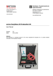
This chapter introduces the parts of the IE-78K0-NS-PA main unit.
The packing box contains the performance board, 2 external sense probes, 20 external sense clips, a packing list,
the user’s manual, and a guarantee card.
If there are any missing or damaged items, please contact an NEC sales representative.
Please make sure to fill out and return the guarantee card that comes with the main unit.
16
User’s Manual U16109EJ1V0UM
CHAPTER 2
PART NAMES
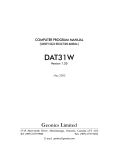
2.1 Parts of Main Unit
Figure 2-1. Performance Board
< Part side >
CN6B
CN4B
CNJTAG1
J1
P2
P1
CN5B
CN7B
EXTCN1
EXTCN2
< Soldering side >
CN4A
CN6A
CN7A
CN5A
User’s Manual U16109EJ1V0UM
17
CHAPTER 2
2.2
PART NAMES
External Sense Probe Names
The IE-78K0-NS-PA includes external sense probes and external sense clips.
(1) External sense probes: 2
Connector No.
10
9
8
7
6
5
4
3
2
1
Table 2-1. Correspondence Between Connector No. and Color of Cable
Connector No.
1
2
3
4
5
6
7
8
9
10
Color of cable
Brown
Red
Orange
Yellow
Green
Blue
Purple
Gray
N.C.
Black
The names of the external sense probes when they are connected to EXTCN1 and EXTCN2 are as follows.
Table 2-2. Bit Configuration When Connecting External Sense Probe to EXTCN1
Connector No.
1
2
3
4
5
6
7
8
9
10
External sense
EXT1
EXT2
EXT3
EXT4
EXT5
EXT6
EXT7
EXT8
N.C.
GND
Table 2-3. Bit Configuration When Connecting External Sense Probe to EXTCN2
Connector No.
1
2
3
4
5
6
7
8
9
10
External sense
EXT9
EXT10
EXT11
EXT12
EXT13
EXT14
EXT15
EXT16
N.C.
GND
Remark
N.C.: No connection
(2) External sense clips: 20 (16 for external sense probes, 2 for GND, and 2 spares)
• Made by Sunhayato Corporation (2 sets of 10)
18
User’s Manual U16109EJ1V0UM
CHAPTER 3
INSTALLATION
This chapter describes how to connect the IE-78K0-NS-PA to the IE-78K0-NS, emulation board, etc.
Caution Connecting and removing cables or components from the target system and changing the
settings of switches, etc. should be carried out after turning off the power supply of the IE
system and the target system.
User’s Manual U16109EJ1V0UM
19
CHAPTER 3 INSTALLATION
(1) Connecting emulation board (IE-780×××
×××-NS-EM1)
×××
The IE-780×××-NS-EM1 is sold separately.
Figure 3-1. Connecting Emulation Board (IE-780×××
×××-NS-EM1)
(1/2)
×××
<1> Remove the screws from the sides of the main
<2> Remove the first and second plates from the
unit, and then remove the top cover.
bottom by removing the screws.
<3> Connect the IE-78K0-NS-PA and fix the
Caution Only when connecting the IE-78018-
spacers (metal) included with this product at
NS-EM1 on the IE-78K0-NS-PA,
five points on the board.
remove spacer 1 (metal) of the
following figure and replace spacers
2 and 3 (metal) with spacers (plastic)
included with this product.
Fix here
Included
spacer
Included
spacer
Fix
Fix
Spacer 1
Spacers 2 and 3
IE-78K0-NS-PA
<4> Connect the IE-780×××-NS-EM1 to the
<5> When using an emulation probe, connect the
IE-78K0-NS-PA and fasten the two screws.
corresponding emulation probe.
IE-780×××-NS-EM1
Refer to (4) for the emulation
probe connection method.
IE-78K0-NS-PA
Refer to (3) for the
external sense probe
connection method.
20
User’s Manual U16109EJ1V0UM
CHAPTER 3 INSTALLATION
Figure 3-1. Connecting Emulation Board (IE-780×××
×××-NS-EM1)
(2/2)
×××
<6> Replace the top cover and fasten the four
screws on the sides.
IE-780×××-NS-EM1
IE-78K0-NS-PA
User’s Manual U16109EJ1V0UM
21
CHAPTER 3 INSTALLATION
(2) Connecting I/O board (IE-78K0-NS-P0×
×) and emulation board (IE-780×××
×××-NS-EM4)
×××
The IE-78K0-NS-P0× and IE-780×××-NS-EM4 are sold separately.
Figure 3-2. Connecting I/O Board (IE-78K0-NS-P0×
×) and Emulation Board (IE-780×××
×××-NS-EM4)
(1/2)
×××
<1> Remove the screws from the sides of the main
<2> Remove the first and third plates from the
unit, and then remove the top cover.
bottom by removing the screws.
<3> Connect the IE-78K0-NS-PA and fix the
<4> Connect the IE-78K0-NS-P0× on the IE-78K0-
spacers (metal) included with this product at
NS-PA and fix the spacers included with the IE-
five points on the board.
78K0-NS-P0× at the four corners.
Included
spacer
Fix here
Included
spacer
Fix
Included
spacer
Included
spacer
Fix
IE-78K0-NS-P0×
Fix
Fix
IE-78K0-NS-PA
IE-78K0-NS-PA
<5> Connect the IE-780×××-NS-EM4 on the IE78K0-NS-P0×, and fasten the screws at the
<6> When using an emulation probe, connect the
corresponding emulation probe.
four corners.
IE-780×××-NS-EM4
IE-78K0-NS-P0×
IE-78K0-NS-PA
Refer to (4) for the emulation
probe connection method.
Refer to (3) for the external sense
probe connection method.
22
User’s Manual U16109EJ1V0UM
CHAPTER 3 INSTALLATION
Figure 3-2. Connecting I/O Board (IE-78K0-NS-P0×
×) and Emulation Board (IE-780×××
×××-NS-EM4)
(2/2)
×××
<7> Replace the top cover and fasten the four
screws on the sides.
IE-780×××-NS-EM4
IE-78K0-NS-P0×
IE-78K0-NS-PA
User’s Manual U16109EJ1V0UM
23
CHAPTER 3 INSTALLATION
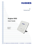
(3) Connecting external sense probe
Figure 3-3. Connecting External Sense Probe
Performance board
IE-78K0-NS-PA
External sense probe (included × 2)
EXTCN1
Ground line (black)
EXTCN2
Ground line (black)
24
User’s Manual U16109EJ1V0UM
CHAPTER 3 INSTALLATION
(4) Connecting emulation probe (NP-×××××
×××××)
×××××
NP-××××× is sold separately.
Figure 3-4. Connecting Emulation Probe
Emulation probe
(NP-×××××)
IE-78K0-NS-PA
IE-780×××-NS-EM1
IE-78K0-NS
Emulation probe
(NP-×××××)
IE-78K0-NS-PA
IE-780×××-NS-EM4
IE-78K0-NS
IE-78K0-NS-P0×
Caution The emulation probe (NP-×××××
×××××)
××××× mounting location varies depending on the emulation board in
use. For details, refer to the user’s manual of the corresponding emulation board.
User’s Manual U16109EJ1V0UM
25
CHAPTER 4
EXTERNAL SENSE SPECIFICATIONS
Up to 16-bit data can be input to the IE-78K0-NS-PA from the target system via an external sense probe.
Also, when using an external event input, input a level of at least 2 CPU clocks.
Table 4-1. Electrical Specifications of External Sense
Parameter
Input voltage, high
Input voltage, low
MIN. [V]
Note
Target voltage
× 0.7
0
Note 2.0 V when the target voltage is less than 2.0 V.
26
User’s Manual U16109EJ1V0UM
MAX. [V]
Target voltageNote
Target voltageNote × 0.3
CHAPTER 5
CAUTIONS
(1) When debugging is performed by connecting the performance board IE-78K0-NS-PA to the in-circuit emulator
IE-78K0-NS and the corresponding emulation board, use an in-circuit emulator or an integrated debugger that
satisfies the following conditions.
• Use an in-circuit emulator IE-78K0-NS with control code D or later.
• Use version 2.00 or later of the integrated debugger ID78K0-NS.
(2) If it is set that DMM or snap shot occurs during the measurement section of the execution time, the execution
time measurement value becomes larger than the actual value.
{ Countermeasure: Do not specify DMM or snap shot during the measurement section of the execution
time.
(3) When section trace is specified and then DMM or snap shot is specified, the trace data may not appear
correctly.
{ Countermeasure: Do not set a DMM or snap shot event when performing a section trace.
Do not set a section trace when performing a DMM or snap shot event.
User’s Manual U16109EJ1V0UM
27
[MEMO]
28
User’s Manual U16109EJ1V0UM
[MEMO]
User’s Manual U16109EJ1V0UM
29
[MEMO]
30
User’s Manual U16109EJ1V0UM
Facsimile Message
From:
Name
Company
Tel.
Although NEC has taken all possible steps
to ensure that the documentation supplied
to our customers is complete, bug free
and up-to-date, we readily accept that
errors may occur. Despite all the care and
precautions we've taken, you may
encounter problems in the documentation.
Please complete this form whenever
you'd like to report errors or suggest
improvements to us.
FAX
Address
Thank you for your kind support.
North America
Hong Kong, Philippines, Oceania
NEC Electronics Inc.
NEC Electronics Hong Kong Ltd.
Corporate Communications Dept. Fax: +852-2886-9022/9044
Fax: +1-800-729-9288
+1-408-588-6130
Korea
Europe
NEC Electronics Hong Kong Ltd.
NEC Electronics (Europe) GmbH
Seoul Branch
Market Communication Dept.
Fax: +82-2-528-4411
Fax: +49-211-6503-274
Taiwan
NEC Electronics Taiwan Ltd.
Fax: +886-2-2719-5951
South America
NEC do Brasil S.A.
Fax: +55-11-6462-6829
Japan
NEC Semiconductor Technical Hotline
Fax: +81- 44-435-9608
P.R. China
NEC Electronics Shanghai, Ltd.
Fax: +86-21-6841-1137
Asian Nations except Philippines
NEC Electronics Singapore Pte. Ltd.
Fax: +65-250-3583
I would like to report the following error/make the following suggestion:
Document title:
Document number:
Page number:
If possible, please fax the referenced page or drawing.
Document Rating
Excellent
Good
Acceptable
Poor
Clarity
Technical Accuracy
Organization
CS 02.3