1
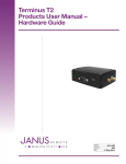
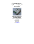
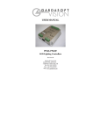
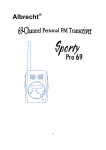
CC3200 SimpleLink™ Wi-Fi® and IoT Solution
with MCU LaunchPad Hardware
User's Guide
Literature Number: SWRU372
June 2014
Contents
1
Introduction ......................................................................................................................... 4
1.1
2
3
4
5
2
CC3200 LaunchPad ..................................................................................................... 4
............................................................................................................. 4
.......................................................................................................... 5
1.4
FCC/IC Regulatory Compliance ........................................................................................ 5
Hardware Description ........................................................................................................... 5
2.1
Block Diagram ........................................................................................................... 6
2.2
Hardware Features....................................................................................................... 6
2.3
Connecting a BoosterPack .............................................................................................. 7
2.4
Jumpers, switches and LEDs ........................................................................................... 7
2.5
Power..................................................................................................................... 14
2.6
Measure CC3200 Current Draw ...................................................................................... 16
2.7
RF Connections ......................................................................................................... 19
2.8
Design Files ............................................................................................................. 19
Software Examples ............................................................................................................. 20
3.1
Development Environment Requirements ........................................................................... 20
Additional Resources.......................................................................................................... 20
4.1
LaunchPad Wiki ......................................................................................................... 20
4.2
Information on the CC3200 ............................................................................................ 20
4.3
Download CCS, IAR .................................................................................................... 21
4.4
The CC3200 Code Examples ......................................................................................... 21
4.5
CC3200 Application Notes ............................................................................................ 21
4.6
The Community ......................................................................................................... 21
Known Limitations.............................................................................................................. 21
5.1
Hardware Limitations ................................................................................................... 21
1.2
Key Features
1.3
What's Included
Table of Contents
SWRU372 – June 2014
Submit Documentation Feedback
Copyright © 2014, Texas Instruments Incorporated
www.ti.com
List of Figures
1
CC3200 LaunchPad EVM Overview ...................................................................................... 5
2
CC3200 Block Diagram ..................................................................................................... 6
3
Pn-1 Marking on the LaunchPad (white triangle) ........................................................................ 7
4
JTAG Headers
5
I2C Connections ............................................................................................................. 8
6
UART Signals ................................................................................................................ 9
7
SOP Jumpers ............................................................................................................... 10
8
2x20 Pin Connector
9
Powering From USB ....................................................................................................... 15
10
Battery Power ............................................................................................................... 16
11
Measuring Low Power ..................................................................................................... 17
12
Measuring Active Power................................................................................................... 18
13
Radiated Testing Using Chip Antenna
14
Board Set for Conducted Testing ........................................................................................ 19
...............................................................................................................
.......................................................................................................
..................................................................................
7
14
19
List of Tables
...............................................................................................................
1
JTAG Headers
2
Jumper Settings .............................................................................................................. 8
3
Default I2C Addresses ...................................................................................................... 9
4
Jumper Settings .............................................................................................................. 9
5
UART Signals ................................................................................................................ 9
6
SOP Lines ................................................................................................................... 10
7
Miscellaneous Settings .................................................................................................... 11
8
Push Buttons ................................................................................................................ 12
9
LEDs ......................................................................................................................... 13
10
Change Log ................................................................................................................. 20
SWRU372 – June 2014
Submit Documentation Feedback
List of Figures
Copyright © 2014, Texas Instruments Incorporated
8
3
User's Guide
SWRU372 – June 2014
CC3200 SimpleLink™ Wi-Fi® and IoT Solution with MCU
LaunchPad Hardware
1
Introduction
1.1
CC3200 LaunchPad
The high performance CC3200 is the industry's first single-chip Microcontroller (MCU) with built-in Wi-Fi
connectivity for the LaunchPad™ ecosystem. Created for the Internet of Things (IoT), the SimpleLink WiFi CC3200 device is a wireless MCU that integrates a high-performance ARM® Cortex®-M4 MCU allowing
customers to develop an entire application with a single IC. With on-chip Wi-Fi, internet and robust
security protocols, no prior Wi-Fi experience is needed for faster development.
The CC3200 LaunchPad is a low-cost evaluation platform for ARM® Cortex™-M4F-based
microcontrollers. The LaunchPad design highlights the CC3200 Internet-on-a-chip™ solution and WiFi
capabilities. The CC3200 LaunchPad also features programmable user buttons, RGB LED for custom
applications and onboard emulation for debugging. The stackable headers of the CC3200 LaunchPad XL
interface demonstrate how easy it is to expand the functionality of the LaunchPad when interfacing with
other peripherals on many existing BoosterPack add-on boards such as graphical displays, audio codec,
antenna selection, environmental sensing, and much more. Figure 1 shows a photo of the CC3200
LaunchPad.
Free software development tools are also available, including TI’s Eclipse-based Code Composer
Studio™ and IAR Embedded Workbench®. More information about the LaunchPad, the supported
BoosterPacks, and the available resources can be found at TI’s LaunchPad portal. Also visit the CC3200
Wiki page for design resources and example projects.
NOTE: The antennas used for this transmitter must be installed to provide a separation distance of
at least 20 cm from all persons and must not be co-located or operating in conjunction with
any other antenna or transmitter.
1.2
Key Features
•
•
•
•
•
•
•
•
CC3200, SimpleLink Wi-Fi, internet-on-a-chip™ solution with integrated MCU
40-pin LaunchPad standard that leverages the BoosterPack ecosystem
FTDI based JTAG emulation with serial port for Flash programming
Two buttons and three LEDs for user interaction
Backchannel universal asynchronous receiver/transmitter (UART) through USB to PC
On-board chip antenna with U.FL for conducted testing
On-board accelerometer and temperature sensor for out-of-box demo
Micro USB connector for power and debug connections
SimpleLink, LaunchPad, Code Composer Studio are trademarks of Texas Instruments.
ARM® Cortex is a trademark of ARM Limited.
ARM, Cortex are registered trademarks of ARM Limited.
IAR Embedded Workbench is a registered trademark of IAR Systems AB.
Wi-Fi is a registered trademark of Wi-Fi Alliance.
All other trademarks are the property of their respective owners.
4
CC3200 SimpleLink™ Wi-Fi® and IoT Solution with MCU LaunchPad
Hardware
Copyright © 2014, Texas Instruments Incorporated
SWRU372 – June 2014
Submit Documentation Feedback
Introduction
www.ti.com
1.3
What's Included
Kit Contents
• CC3200 LaunchPad development tool
• Micro USB cable
• Quick start guide
1.4
FCC/IC Regulatory Compliance
The CC3200 SimpleLink Wi-Fi and IoT solution with MCU LaunchPad hardware is FCC Part 15 and IC
ICES-003 Class A compliant.
2
Hardware Description
Figure 1. CC3200 LaunchPad EVM Overview
SWRU372 – June 2014
Submit Documentation Feedback
CC3200 SimpleLink™ Wi-Fi® and IoT Solution with MCU LaunchPad
Hardware
Copyright © 2014, Texas Instruments Incorporated
5
Hardware Description
2.1
www.ti.com
Block Diagram
Figure 2. CC3200 Block Diagram
2.2
Hardware Features
•
•
•
•
•
•
•
•
•
•
•
•
6
CC3200, SimpleLink Wi-Fi, internet-on-a-chip solution with integrated MCU40-pin LaunchPad standard
that leverages the BoosterPack ecosystem
FTDI-based JTAG emulation with serial port for Flash programming
Supports both 4-wire JTAG and 2-wire SWD
Two buttons and three LEDs for user interaction
Virtual COM port UART through USB on PC
On-board chip antenna with U.FL for conducted testing
On-board accelerometer and temperature sensor for out-of-box demo with option to isolate them from
the inter-integrated circuit (I2C) bus
Micro USB connector for power and debug connections
Headers for current measurement and external JTAG connection
Bus-powered device with no external power required for Wi-Fi
Long range transmission with highly optimized antenna (200m typical in open air with a 6dBi antenna
AP)
Can be powered externally, with 2xAA or 2xAAA alkaline batteries working down to 2.3V typical (typ)
CC3200 SimpleLink™ Wi-Fi® and IoT Solution with MCU LaunchPad
Hardware
Copyright © 2014, Texas Instruments Incorporated
SWRU372 – June 2014
Submit Documentation Feedback
Hardware Description
www.ti.com
2.3
Connecting a BoosterPack
A compatible BoosterPack can be stacked on top of the LaunchPad using the 2x20 pin connectors. Note
that the connectors do not have a “key” to prevent the misalignment of the pins or reverse connection.
Ensure that Vcc and 5V pins, are aligned with the BoosterPack header pins. On the CC3200 LaunchPad,
a small white triangle symbol is provided near Pin-1 (see Figure 3) to orient all BoosterPacks. This same
marking, provided on compatible BoosterPacks, needs to be aligned before powering up the boards.
Figure 3. Pn-1 Marking on the LaunchPad (white triangle)
2.4
2.4.1
Jumpers, switches and LEDs
JTAG Headers
The headers are provided on the board to isolate the CC3200 device from the mounted FTDI JTAG
emulator. These jumpers are shorted by default when the board is shipped from TI. To connect an
external emulator, remove these jumpers and place the external emulator on the pins closer to the
CC3200 device.
Figure 4. JTAG Headers
SWRU372 – June 2014
Submit Documentation Feedback
CC3200 SimpleLink™ Wi-Fi® and IoT Solution with MCU LaunchPad Hardware
Copyright © 2014, Texas Instruments Incorporated
7
Hardware Description
www.ti.com
Table 1. JTAG Headers
Reference
J8 (TCK)
(1)
J9 (TMS)
(1)
Usage
Comments
JTAG
Short : Routes the on-board emulator to the CC3200
J10 (TDI)
Open: Isolate the on-board emulator from the CC3200.
J11(TDO)
(1)
For the SWD mode, only TCK and TMS need to be shorted to the CC3200.
When a battery is used, be sure to disconnect all the JTAG headers to prevent any reverse leakage
current.
2.4.2
I2C Connections
The board features an accelerometer and a temperature sensor for the out-of-box demo. These are
connected to the I2C bus and can be isolated using the jumpers provided.
Figure 5. I2C Connections
By removing J2 and J3, the accelerometer and the temperature sensors are isolated from the I2C bus.
Note that this also removes any pull-up resistor from the I2C bus.
2.4.2.1
Jumper Settings
Table 2. Jumper Settings
Reference
2.4.2.2
8
Usage
Comments
J2
I2C SDA
Short : Connect the CC3200 I2C bus to the on-board sensors with pull-up
Open : Isolate the sensors from the CC3200
J3
I2C SCL
Short : Connect the CC3200 I2C bus to the on-board sensors with pull-up
Open : Isolate the sensors from the CC320
J4
INT
Short : Connect the accelerometer interrupt to the CC3200 on GPIO13
Default I2C Address
CC3200 SimpleLink™ Wi-Fi® and IoT Solution with MCU LaunchPad
Hardware
Copyright © 2014, Texas Instruments Incorporated
SWRU372 – June 2014
Submit Documentation Feedback
Hardware Description
www.ti.com
Table 3. Default I2C Addresses
2.4.3
Sensor Type
Ref
Part Number
Slave Address
Temp sensor
U6
TMP008
0x41
Accelerometer
U10
BMA222
0x18
Power Connections
The board can be powered by using the on-board micro USB connector. An on-board LDO provides 3.3 V
for the CC3200 and the rest of the board to operate. This supply can be isolated from the LDO using the
jumpers on the board.
Table 4. Jumper Settings
2.4.4
Reference
Usage
J12
Current
measurement
Comments
Measures the current flowing into the CC3200 device.
J13
Board power
Short: Supply the board power from the on-board LDO.
Open: Supply the board power from the J20 (battery connector)
J19
5 V power
5 V output from the USB VBUS (has a diode drop of up to 0.4 V)
J20
3.3 V power input
Can be used to power the board from an external 2XAA battery pack. It has in-built reverse
voltage protection to prevent the battery from being plugged in the reverse manner.
UART Signals
The board supports a USB-based virtual COM port, which is used on the FTDI device FT2232D. There
are two ports on the FT2232: the first port is dedicated for the emulation (JTAG/SWD) and the second port
is used for the virtual COM port. The UART can also be routed to the 20-pin connector and the selection
is performed using jumpers on the board.
UART for Flashing Mode
UART for BoosterPack
Figure 6. UART Signals
Table 5. UART Signals
Reference
Usage
J6, J7
UART for Flash
programming
SWRU372 – June 2014
Submit Documentation Feedback
Comments
Short 1-2: Route the signals to the 20 pin connector.
Short 2-3: Route the signals to the FTDI for Flash programming.
CC3200 SimpleLink™ Wi-Fi® and IoT Solution with MCU LaunchPad
Hardware
Copyright © 2014, Texas Instruments Incorporated
9
Hardware Description
2.4.5
www.ti.com
Sense on Power
The CC3200 can be set to operate in three different modes based on the state of the Sense on Power
(SOP) lines. These are pins 21, 34, 35 on the CC3200 device. The state of the device is described in
Table 6.
Table 6. SOP Lines
Usage
SOP[2:0]
Comments
100 = Flash programming
000 = Functional mode + 4 Wire JTAG
001 = Functional mode + 2 Wire JTAG
Note: SOP[2:0] corresponds to J15, J16, and J17, in the LaunchPad schematic design.
Figure 7. SOP Jumpers
10
CC3200 SimpleLink™ Wi-Fi® and IoT Solution with MCU LaunchPad
Hardware
Copyright © 2014, Texas Instruments Incorporated
SWRU372 – June 2014
Submit Documentation Feedback
Hardware Description
www.ti.com
2.4.6
Other Miscellaneous
Table 7. Miscellaneous Settings
Reference
Usage
J4
Accelerometer
Interrupt
Short = Route the Accelerometer sensor interrupt to the GPIO_13
Open = Isolates the Interrupt to the GPIO_13
J5
Debug Header
To observe the Network Processor (NWP), MAC Logs.
J14
SOP2 Isolation
Isolate SOP2 (GPIO_25) from the 20 pin connector
SWRU372 – June 2014
Submit Documentation Feedback
Comments
CC3200 SimpleLink™ Wi-Fi® and IoT Solution with MCU LaunchPad
Hardware
Copyright © 2014, Texas Instruments Incorporated
11
Hardware Description
2.4.7
www.ti.com
Push Buttons and LEDs
Table 8. Push Buttons
Reference
Usage
Comments
SW1
RESET
This is used to RESET the CC3200 device. This signal is also output on
the 20-pin connector to RESET any external BoosterPack which may be
stacked.
SW2
GPIO_22
When pushed, the GPIO_22 will be pulled to VCC.
SW3
GPIO_13
When pushed, the GPIO_13 will be pulled to VCC.
12
CC3200 SimpleLink™ Wi-Fi® and IoT Solution with MCU LaunchPad
Hardware
Copyright © 2014, Texas Instruments Incorporated
SWRU372 – June 2014
Submit Documentation Feedback
Hardware Description
www.ti.com
Table 9. LEDs
Refere
nce
Colo4
Usage
D1
Yellow
nRESET
This LED is used to indicate the state of nRESET pin. If this LED is
glowing, the device is functional.
D2
Green
Debug
This LED glows whenever the debugging it enabled over the JTAG
D4
RED
Power
Indicates when the 3.3 V power is supplied to the board.
D5
GREEN
GPIO_11
(1)
Glows when the GPIO is logic-1
D6
YELLOW
GPIO_10
(1)
Glows when the GPIO is logic-1
D7
RED
(1)
Comments
GPIO_09
Glows when the GPIO is logic-1
GPIO_10 and GPIO_11 are used as I2C also. So whenever the pull-ups are enabled, the LEDs would glow.
SWRU372 – June 2014
Submit Documentation Feedback
CC3200 SimpleLink™ Wi-Fi® and IoT Solution with MCU LaunchPad
Hardware
Copyright © 2014, Texas Instruments Incorporated
13
Hardware Description
2.4.8
www.ti.com
2x20 Pin Connector Assignment
The signal assignment on the 2x20 pin connector is shown in Figure 8. The P1-Pn naming convention is
used for 2x20 pin connectors only.
P1
P3
Dev Dev
Ref Signal
Pin# Pin# Signal
1 3.3V
5V
2 ADC_CH1
58
GND
3 UART0_RX
4
57 ADC_CH0
4 UART0_TX
3
60 ADC_CH3
5 GPIO
61 58* ADC_CH1
6 ADC_CH2
59 59* ADC_CH2
7
8
9
10
SPI_CLK
GPIO
I2C_SCL
I2C_SDA
5
62
1
2
63
53
64
50
P4
CC3200
AUD_SYNC
AUD_CLK
AUD_DOUT
AUD_DIN
P2
Dev
Signal
Pin#
PWM
2*
PWM
1*
PWM
17*
PWM
64*
CCAP/GPIO 21*
CCAP/GPIO 18*
GPIO
62*
GPIO
60*
GPIO
16
GPIO
17
Dev
Pin# Signal
GND
18 GPIO
8 SPI_CS
45 GPIO
RESET_OUT
7 SPI_DOUT
6 SPI_DIN
21 GPIO
55 GPIO
15 GPIO
Ref
1
2
3
4
5
6
7
8
9
10
Figure 8. 2x20 Pin Connector
The signal mappings are as indicated in above table shown in Figure 8. All the signals are referred by the
pin number in the SDK and Figure 8 shows the default mappings. Note that some of the pins are repeated
across the connector. For instance, pin 62 is available on P1 and P4, but only P1 is connected by default.
The signal on P4 is marked with a *(star) to signify that it is not connected by default. It can be routed to
the pin by using a 0 Ω resistor in the path. For the exact resistor placement, see the schematics and
placement diagram.
2.5
Power
The LaunchPad is designed such that it can be powered by the USB connection or by external
2xAA/2xAAA batteries.
14
CC3200 SimpleLink™ Wi-Fi® and IoT Solution with MCU LaunchPad
Hardware
Copyright © 2014, Texas Instruments Incorporated
SWRU372 – June 2014
Submit Documentation Feedback
Hardware Description
www.ti.com
2.5.1
USB Power
The LaunchPad is designed to work from the USB provided power supply. The LaunchPad will enumerate
as a bus-powered device on the computer. When the board is powered from the USB connector, make
sure that the jumpers are placed on the following headers, as shown in Figure 9.
J12 (shorted)
J13 (shorted)
Figure 9. Powering From USB
SWRU372 – June 2014
Submit Documentation Feedback
CC3200 SimpleLink™ Wi-Fi® and IoT Solution with MCU LaunchPad
Hardware
Copyright © 2014, Texas Instruments Incorporated
15
Hardware Description
2.5.2
www.ti.com
Battery Power (2 x 1.5 V)
The LaunchPad can also be powered from an external battery pack by feeding the voltage on the J20
header. This input features reverse voltage protection to ensure that the board is not damaged due to an
accidental reverse voltage. The following care should be taken while using the board with a battery
1. Remove the USB cable.
2. Plug-in the battery pack on J20 with correct polarity (see Figure 10).
Figure 10. Battery Power
2.5.3
BoosterPack Power Supply
The CC3200 LaunchPad can be powered by a stacked booster-pack which can provide a 3.3 V power on
P1.1. During this mode, ensure that the J13 is removed so that the on-board LDO is not overloaded.
2.6
Measure CC3200 Current Draw
To measure the current draw of the CC3200, use the 3V3 jumper on the jumper isolation block. (J12). The
current measured in this mode includes only the CC3200 current and no external blocks. However, if a
GPIO of the CC3200 is driving a high current load like LED, then that is also included in this
measurement.
16
CC3200 SimpleLink™ Wi-Fi® and IoT Solution with MCU LaunchPad
Hardware
Copyright © 2014, Texas Instruments Incorporated
SWRU372 – June 2014
Submit Documentation Feedback
Hardware Description
www.ti.com
2.6.1
Measuring Low Power (< 1mA)
Follow these steps to measure ultra-low power:
Figure 11. Measuring Low Power
1. Remove the 3V3 jumper (J12); attach an ammeter across this jumper.
2. Make sure that the CC3200 is not driving any high current loads directly like an LED as this can cause
large current drawn.
3. Begin target execution and set the device to low-power modes (LPDS or Hibernate).
4. Measure the current. (Keep in mind that if the current levels are fluctuating, it may be difficult to get a
stable measurement. It is easier to measure quiescent states.)
SWRU372 – June 2014
Submit Documentation Feedback
CC3200 SimpleLink™ Wi-Fi® and IoT Solution with MCU LaunchPad
Hardware
Copyright © 2014, Texas Instruments Incorporated
17
Hardware Description
2.6.2
www.ti.com
Measuring Active Power
Figure 12. Measuring Active Power
1. Remove the 3V3 jumper (J12).
2. Solder a 0.1 Ω resistor on the board at R62. Or, attach a jumper wire between J12 so that it can be
used with a current probe.
3. Measure the voltage across the R62 using an oscilloscope with a differential probe. (For the current
probe, coil the wire around the sensor multiple times for good sensitivity).
4. An ammeter can also be used for this measurement, but the results may be erroneous due to the
switching nature of the current.
18
CC3200 SimpleLink™ Wi-Fi® and IoT Solution with MCU LaunchPad
Hardware
Copyright © 2014, Texas Instruments Incorporated
SWRU372 – June 2014
Submit Documentation Feedback
Hardware Description
www.ti.com
2.7
2.7.1
RF Connections
Radiated Testing (AP connection)
By default the board ships with the RF signals routed to the on-board chip antenna. An on-board u.fl
(Murata) connector provides a means to perform the testing in the lab using a compatible cable.
Resistor mounted
towards antenna path
Murata
Connector
Figure 13. Radiated Testing Using Chip Antenna
Resistor mounted
towards U.FL
Murata connector
Figure 14. Board Set for Conducted Testing
2.8
2.8.1
Design Files
Hardware
All design files include schematics, layout, Bill of Materials (BOM), Gerber files and documentation, which
are made available for download from the following URL: http://www.ti.com/tool/cc3200-launchxl-rd.
SWRU372 – June 2014
Submit Documentation Feedback
CC3200 SimpleLink™ Wi-Fi® and IoT Solution with MCU LaunchPad
Hardware
Copyright © 2014, Texas Instruments Incorporated
19
Software Examples
2.8.2
www.ti.com
Revision History
Table 10. Change Log
PCB Revision
Description
Rev 3.0B
Rev 3.1
• First baseline revision
The
•
•
•
Rev 3.2
2.8.3
main changes pertain to the bill of materials (BOM) and the layout:
Replaced the caps C23, C24 with ceramic ones to minimize leakage current
R62 is made to DNP by default so that the jumper is used to measure the hibernate current
Misc silk screen changes in order to clearly annotate components on the board.
• Layout changes for the DC-DC section in order to improve the mask margin
• Updated the silk screen to reflect the final markings.
Software
All design files including firmware patches, software example projects, and documentation are made
available from the SimpleLink Wi-Fi Platform page.
The Software Development Kit (SDK) to use with the CC3200 LaunchPad can be obtained from
http://www.ti.com/tool/cc3200sdk.
3
Software Examples
3.1
Development Environment Requirements
To use any of the following software examples with the LaunchPad, you must have an integrated
development environment (IDE) that supports the CC3200 device.
For more details on where to download the latest IDE, see Section 4.3.
The CC3200 Programmer's guide (SWRU369) has detailed information on software environment setup,
and examples. Please refer to this document for further details on the software sample examples.
3.1.1
CCS
CCS 6.0 or higher is required. When CCS has been launched, and a workspace directory chosen, use
Project → Import Existing CCS Eclipse Project. Direct it to the desired demo’s project directory containing
main.c.
3.1.2
IAR
IAR 6.70 or higher is required. To open the demo in IAR, simply choose File → Open → Workspace…,
and direct it to the *.eww workspace file inside the \IAR subdirectory of the desired demo. All workspace
information is contained within this file.
The subdirectory also has an *.ewp project file; this file can be opened into an existing workspace, using
Project → Add-Existing-Project….
4
Additional Resources
4.1
LaunchPad Wiki
Most updated information would be available on the CC3200 Wiki page.
4.2
Information on the CC3200
For more information on CC3200 visit the product page (http://www.ti.com/product/cc3200) (datasheet and
key documents like the technical reference manual (TRM)) and Wiki (http://www.ti.com/simplelinkwifi-wiki)
(Organize information for Getting started, Hardware details, Software details including porting information,
Test/Certification and Support and Community).
20
CC3200 SimpleLink™ Wi-Fi® and IoT Solution with MCU LaunchPad
Hardware
Copyright © 2014, Texas Instruments Incorporated
SWRU372 – June 2014
Submit Documentation Feedback
Additional Resources
www.ti.com
4.3
Download CCS, IAR
Although the files can be viewed with any text editor, more can be done with the projects if they’re opened
with a development environment like Code Composer Studio (CCS), IAR, or Energia.
CCS and IAR are each available in a full version, or a free, code-size-limited version. The full out-of-box
demo cannot be built with the free version of CCS or IAR (IAR Kickstart) due to the code size limit. To
bypass this limitation, a code-size-limited CCS version is provided, that has most functionality integrated
into a library. The code that is built into the library is able to be viewed by the user, but it cannot be edited.
For full functionality download the full version of either CCS or IAR.
4.4
The CC3200 Code Examples
The user's guide for each example can be found within the Software Development Kit (SDK), or on the
Simplelink Wiki.
4.5
CC3200 Application Notes
There are many application notes with practical design examples and topics located at the SimpleLink(TM)
Wi-Fi(R) main wiki page, and the main landing page.
4.6
4.6.1
The Community
TI E2E Community
Search the forums at e2e.ti.com. If you cannot find your answer, post your question to the community!
5
Known Limitations
5.1
Hardware Limitations
5.1.1
Floating S-Flash Lines
The SPI lines routed from the CC3200 to the on-board serial Flash are not pulled up/down using resistors
on the board. When the device enters “Hibernate” state these pins can be floating and high currents can
be drawn by the serial Flash.
5.1.2
Floating IO
All the GPIO outputs from the CC3200 device would float while the device enters hibernate state. This can
cause glitches on the lines if they are not pulled externally.
SWRU372 – June 2014
Submit Documentation Feedback
CC3200 SimpleLink™ Wi-Fi® and IoT Solution with MCU LaunchPad
Hardware
Copyright © 2014, Texas Instruments Incorporated
21
IMPORTANT NOTICE
Texas Instruments Incorporated and its subsidiaries (TI) reserve the right to make corrections, enhancements, improvements and other
changes to its semiconductor products and services per JESD46, latest issue, and to discontinue any product or service per JESD48, latest
issue. Buyers should obtain the latest relevant information before placing orders and should verify that such information is current and
complete. All semiconductor products (also referred to herein as “components”) are sold subject to TI’s terms and conditions of sale
supplied at the time of order acknowledgment.
TI warrants performance of its components to the specifications applicable at the time of sale, in accordance with the warranty in TI’s terms
and conditions of sale of semiconductor products. Testing and other quality control techniques are used to the extent TI deems necessary
to support this warranty. Except where mandated by applicable law, testing of all parameters of each component is not necessarily
performed.
TI assumes no liability for applications assistance or the design of Buyers’ products. Buyers are responsible for their products and
applications using TI components. To minimize the risks associated with Buyers’ products and applications, Buyers should provide
adequate design and operating safeguards.
TI does not warrant or represent that any license, either express or implied, is granted under any patent right, copyright, mask work right, or
other intellectual property right relating to any combination, machine, or process in which TI components or services are used. Information
published by TI regarding third-party products or services does not constitute a license to use such products or services or a warranty or
endorsement thereof. Use of such information may require a license from a third party under the patents or other intellectual property of the
third party, or a license from TI under the patents or other intellectual property of TI.
Reproduction of significant portions of TI information in TI data books or data sheets is permissible only if reproduction is without alteration
and is accompanied by all associated warranties, conditions, limitations, and notices. TI is not responsible or liable for such altered
documentation. Information of third parties may be subject to additional restrictions.
Resale of TI components or services with statements different from or beyond the parameters stated by TI for that component or service
voids all express and any implied warranties for the associated TI component or service and is an unfair and deceptive business practice.
TI is not responsible or liable for any such statements.
Buyer acknowledges and agrees that it is solely responsible for compliance with all legal, regulatory and safety-related requirements
concerning its products, and any use of TI components in its applications, notwithstanding any applications-related information or support
that may be provided by TI. Buyer represents and agrees that it has all the necessary expertise to create and implement safeguards which
anticipate dangerous consequences of failures, monitor failures and their consequences, lessen the likelihood of failures that might cause
harm and take appropriate remedial actions. Buyer will fully indemnify TI and its representatives against any damages arising out of the use
of any TI components in safety-critical applications.
In some cases, TI components may be promoted specifically to facilitate safety-related applications. With such components, TI’s goal is to
help enable customers to design and create their own end-product solutions that meet applicable functional safety standards and
requirements. Nonetheless, such components are subject to these terms.
No TI components are authorized for use in FDA Class III (or similar life-critical medical equipment) unless authorized officers of the parties
have executed a special agreement specifically governing such use.
Only those TI components which TI has specifically designated as military grade or “enhanced plastic” are designed and intended for use in
military/aerospace applications or environments. Buyer acknowledges and agrees that any military or aerospace use of TI components
which have not been so designated is solely at the Buyer's risk, and that Buyer is solely responsible for compliance with all legal and
regulatory requirements in connection with such use.
TI has specifically designated certain components as meeting ISO/TS16949 requirements, mainly for automotive use. In any case of use of
non-designated products, TI will not be responsible for any failure to meet ISO/TS16949.
Products
Applications
Audio
www.ti.com/audio
Automotive and Transportation
www.ti.com/automotive
Amplifiers
amplifier.ti.com
Communications and Telecom
www.ti.com/communications
Data Converters
dataconverter.ti.com
Computers and Peripherals
www.ti.com/computers
DLP® Products
www.dlp.com
Consumer Electronics
www.ti.com/consumer-apps
DSP
dsp.ti.com
Energy and Lighting
www.ti.com/energy
Clocks and Timers
www.ti.com/clocks
Industrial
www.ti.com/industrial
Interface
interface.ti.com
Medical
www.ti.com/medical
Logic
logic.ti.com
Security
www.ti.com/security
Power Mgmt
power.ti.com
Space, Avionics and Defense
www.ti.com/space-avionics-defense
Microcontrollers
microcontroller.ti.com
Video and Imaging
www.ti.com/video
RFID
www.ti-rfid.com
OMAP Applications Processors
www.ti.com/omap
TI E2E Community
e2e.ti.com
Wireless Connectivity
www.ti.com/wirelessconnectivity
Mailing Address: Texas Instruments, Post Office Box 655303, Dallas, Texas 75265
Copyright © 2014, Texas Instruments Incorporated