1
Interbus Fieldbus Interface C-5
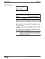
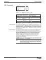
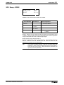
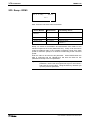
TRANS 01D
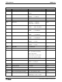
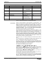
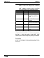
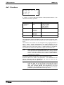
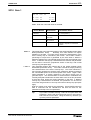
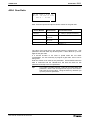
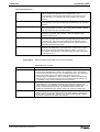
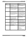
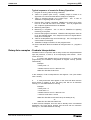
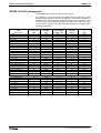
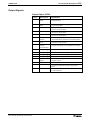
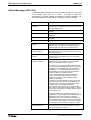
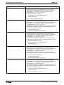
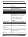
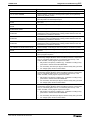
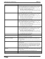
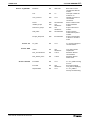
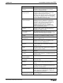
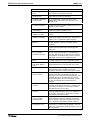
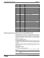
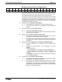
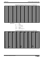
Byte no.
Value
Definition
1
0x08
Bus length of the process data chan.in bytes
2
0x5F
1st byte on bus; 5F91
3
0x91
1st byte on bus; 5F91
4
0x00
Sub-index of object 5F91 (always 00)
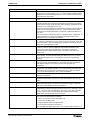
5
0x00
2nd byte on bus; object 5F91 (Word)
6
0x00
2nd byte on bus; object 5F91 (Word)
7
0x00
Sub-index of object 5F91 (always 00)
8
0x5F
3rd byte on bus; 5F92
9
0x92
3rd byte on bus; 5F92
10
0x00
Sub-index of object 5F92 (always 00)
11
0x00
4th byte on bus; object 5F92 (Word)
12
0x00
4th byte on bus; object 5F92 (Word)
13
0x00
Sub-index pf pbject 5F92 (always 00)
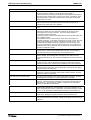
14
0x5F
5th bytes on bus; 5F10
15
0x10
5th byte on bus; 5F10
16
0x00
Sub-index of object 5F10 (always 00)
17
0x00
6th byte on bus; object 5F10 (D-Word)
18
0x00
6th byte on bus; object 5F10 (D-Word)
19
0x00
Sub-index of object 5F10 (always 00)
20
0x00
7th byte on bus; object 5F10 (D-Word)
21
0x00
7th byte on bus; object 5F10 (D-Word)
22
0x00
Sub-index of object 5F10 (always 00)
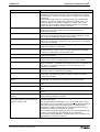
23
0x00
8th byte on bus; object 5F10 (D-Word)
24
0x00
8th byte on bus; object 5F10 (D-Word)
25
0x00
Sub-index of object 5F10 (always 00)
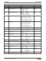
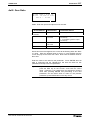
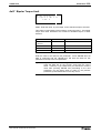
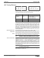
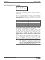
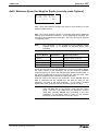
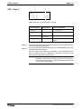
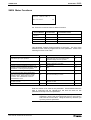
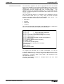
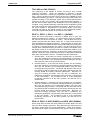
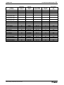
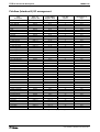
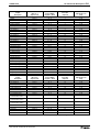
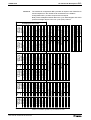
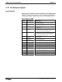
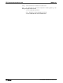
Table C-3: Default data contents of object 6000 in InterBus-S
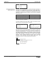
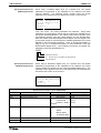
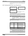
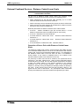
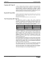
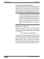
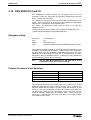
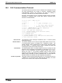
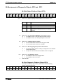
Process Data Output Description with Object 6001
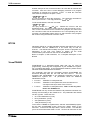
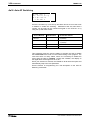
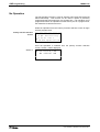
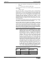
The process data output description is stored in object 6001.
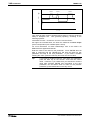
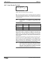
This description contains a copy of the position and the number of the
output words on the bus. The structure is the same as the process input
data description in object 6000.
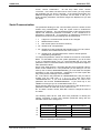
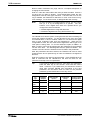
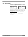
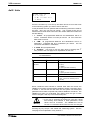
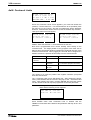
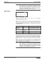
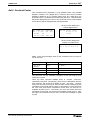
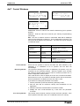
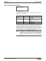
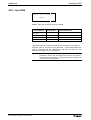
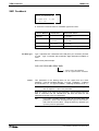
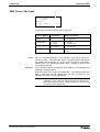
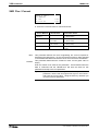
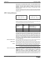
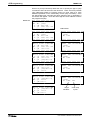
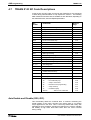
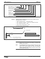
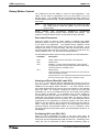
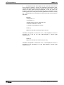
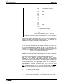
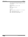
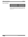
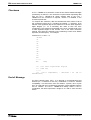
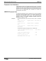
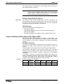
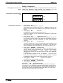
The description relates to the following default configuration.
Example:
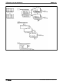
Default configuration in Interbus-S
OUT:
Word 1:
Word 2:
Word 3:
Word 4:
Word 5:
com-Out
5FB1
5FB2
5FB3
5FF1
IN:
com-IN
5F91
5F92
5F10(H)
5F10(L)
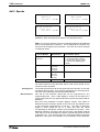
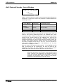
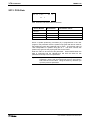
Table C-4: Default assignment of the process data channel in Profibus
DOK-CONTRL-TRANS01D*06-AW02-AE-P