1
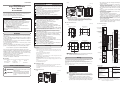
Part names and functions
Key operation and setting
The following shows the flow of key operation:
(1)
man
pv
Display when the power is turned ON.
pv
man
ev1
ev3
ev2
OFF
ot1
ev1
ev2
ev3
ot1
ot2
(3)
(4)
sp
(6) (5)
(9)
enter
OFF
(2)
out
mode
display
para
enter
ot2
mode
display
mode
(5)
sp
out
ot2
ev3
man
ot1
The mode indicators are lit sequentially form the left
during a period of 5 to 6 sec after the power has been
turned ON while both the upper display and lower
display are OFF. When all mode indicators have been
lit, the display is changed to the operation display.
SDC26
pv
ev1
ev2
(2)
sp
out
Cleaning :
When wiping out the SDC25/26, use the soft and dried cloth.
Parts replacement: Do not replace the parts.
Fuse replacement: When replacing the fuse for the power supply wires, make
sure that the replacement fuse complies with all applicable
safety standards.
Standard IEC127, Cutoff Speed Delayed operation type (T),
Rated Voltage 250V, Rated Current 0.5A
SDC26
SDC25
display
para
(6)
para
Keep the
key
pressed for 2 sec.
or longer.
enter
(9)
(10)
para
(10)
No key operation for
3 minutes or more.
display
enter
Press the
or Press the
or
mode
Bank selection display
Operation display
No key operation for
3 minutes or more.
display
Press the
< key.
key.
Optional unit Model No.:
QN212A (800 turns, hole diameter: 12mm)
Maintenance
or
mode
key.
(7)
<
<
C25
key.
Temperature unit setup
Press the
or
key.
Press the
Press the
Press the
para
Panel mounting type
key.
Press the
key.
Press the
or
R0
Relay contact
output NO
Relay contact
output NC
V0
Voltage pulse output
(for SSR drive)
–
VC
Voltage pulse output Current output
(for SSR drive)
VV
Voltage pulse output Voltage pulse output
(for SSR drive) (for SSR drive)
key.
Other banks (Operate
the [para], [ ] and [ ]
keys repeatedly.)
para
key.
or
or
<
Press the
key
key.
<
Other banks (Operate
the [para], [ ] and [ ]
keys repeatedly.)
Other display and
setup (Operate the
[display] key)
display
para
key.
para
Keep the
key
pressed for 2 seconds or longer.
The display and setup status shown above are examples for explanation. Therefore, some
displays or settings are not shown actually according to the model and/or setup contents.
C0
Current output
CC
Current output Current output
U
There are the standard type and special type in the data setup method.
Here, the method is explained in the standard type.
<
AC model (100 to 240Vac) 50/60Hz
D
Display the C0 1 on the upper display in the bank setup mode for the setup bank.
When the [enter] key is pressed, the numerical value on the lower display
will start to flash.
Move the digit or increase/decrease the numeric value by pressing the [<]
[ ] [ ] keys.
When the [enter] key is pressed at the desired numeric value, the flashing
will stop and the data will be set.
–
Universal
A
● Setting example of the PV range type
DC model (24Vac/24Vdc)
1
Event relay output: 3 points
2
Event relay output: 3 points,
Auxiliary output (current output)
(Note 2)
4
Event relay output: 2 points,
(independent contact)
(Note 2)
5
Event relay output: 2 points
(independent contact)
Auxiliary output (current output)
–
(Note 1)
1
Current transformer input: 2 points
Digital input: 4 points
Display the SP- 1 on the upper display in the bank setup mode of the setup
bank.
When the [enter] key is pressed, the numerical value on the lower display
will start to flash.
Move the digit or increase/decrease the numeric value by pressing the [<]
[ ] [ ] keys.
When the [enter] key is pressed at the desired numeric value, the flashing
will stop and the data will be set.
For details of the handling and setting methods, refer to the following user's
manual:
Single Loop Controller SDC25/26 User's Manual "Installation &
Configurations" CP-SP-1149E
(Note 1)
2
Current transformer input: 2 points
Digital input: 4 points
RS-485 communication
<
0
● Setting example of the SP1
Note 1. Current transformer is sold separately .
Note 2. Can not be selected for DC model.
Alarm code table
Failure name
PV input failure
(over range)
AL02
PV input failure
(under range)
AL03
CJ failure
PV input failure
AL1 1
AL70
AL95
CT input failure
(over-range)
(CT input 1 or 2,
or both)
A/D conversion
failure
Parameter failure
AL96
Adjustment data
failure
AL97
Parameter failure
(RAM area)
Adjustment data
failure
(RAM area)
ROM failure
AL98
AL99
Cause
Sensor line break, incorrect
wiring, incorrect PV range
type setting
Sensor line break, incorrect
wiring, incorrect PV range
type setting
Terminal temperature is
faulty (thermocouple).
Sensor line break, incorrect
wiring (RTD)
A current exceeding the upper
limit of the display range was
measured. The number of CT
turns or the number of CT
power wire loops is incorrectly
set, or wiring is incorrect.
Defective A/D converter
0
No additional treatment
D
Inspection certificate provided
T
Tropicalization treatment applied
K
Anti-sulfide treatment applied
B
Tropicalization treatment applied
and Inspection certificate provided
L
Anti-sulfide treatment applied and
Inspection certificate provided
Y
Complying with the traceability
certificate
0
IP65 inapplicable
Specifications
This table shows the alarm display and measures for the abnormal operation of
this controller.
Alarm code
AL0 1
Checking the ambient
temperature.
Checking wiring.
Use a CT with the correct
number of turns for the
display range, reset the
number of CT turns, reset
the number of CT power
wire loops, and/or check
the wiring.
Replace unit.
Re-start the system.
Reset data or replace
unit.
(AL95/97: setting data,
AL96/98: tuning data)
ROM (memory) error
Re-start the system.
Replace unit.
● PV input
Thermocouple:
Corrective action
Checking wiring or
reset PV range type.
• Power turned OFF during
fixing data
• Data corrupted due to noise,
etc.
• Power turned OFF during
fixing data
• Data corrupted due to noise, etc.
Data corrupted due to noise,
etc.
Data corrupted due to noise,etc.
Allowable measured
current:
70.0Aac (800 turns, 1 time)
Formula; Number of turns ÷ (16 x number of
power wire loops) x 1.4
0.0Aac
70.0Aac (800 turns, 1 time)
Formula; Number of turns ÷ (16 x number of
power wire loops) x 1.4
±5%FS
0.1Aac
Display accuracy:
Display resolution:
96 x 96 size model
<
Press the
key.
<
para
<
Press the
key
SP bank selection
Press the
<
display
50.0Aac (800 turns, 1 time)
Formula; Number of turns ÷ (16 x number of
power wire loops)
Display range lower limit:
Display range upper limit:
Specifications
Control output 1 Control output 2
MV display
Current measurement
upper limit:
48 x 96 size model
C26
T
<
Handling Precautions
C01
Sensor
Range
· The accuracy is ±0.3%FS±1 Set value
type
digit, and ±0.6%FS±1 digit for 81
0 to 10mV
The scaling and the decimal
a negative area of the
82 -10 to +10mV point position can be
thermocouple.
83
0 to 100mV
changed variably in a range
The accuracy varies
84
0 to 1V
of -1999 to +9999.
according to the range:
86
1 to 5V
The accuracy of the No.17
87
0 to 5V
(sensor type B) is ±4.0%FS 88
0 to 10V
for a range of 260°C or less, 89
0 to 20mA
±0.4%FS for 260 to 800°C. 90
4 to 20mA
The PV values under 20°C
are not shown.
The accuracy of the No.23 (sensor type PR40-20) is ±2.5%FS
for 0 to 300°C, and ±1.5%FS for 300 to 800°C, ±0.5%FS for 800
to 1900°C.
The accuracy of the No.26 (sensor type gold iron chromel) is
±1.5K.
The accuracy of the No.19 (sensor type PLII) in the range of 0 to
32˚F does not meet the indication accuracy.
· The ranges with a decimal point show figures under decimal point.
or
<
-300 to +900°F
-300 to +900°F
-300 to +400°F
-300 to +400°F
-150 to +500°F
-150 to +500°F
-150 to +400°F
-150 to +400°F
-150 to +300°F
-150 to +300°F
-50 to +400°F
-50 to +400°F
-50 to +200°F
-50 to +200°F
-60 to +100°F
-60 to +100°F
-40 to +140°F
-40 to +140°F
-10 to +140°F
-10 to +140°F
0 to 200°F
0 to 200°F
0 to 400°F
0 to 400°F
0 to 500°F
0 to 500°F
0 to 900°F
0 to 900°F
key.
out
<
-200.0 to +500.0°C
-200.0 to +500.0°C
-200.0 to +200.0°C
-200.0 to +200.0°C
-100.0 to +300.0°C
-100.0 to +300.0°C
-100.0 to +200.0°C
-100.0 to +200.0°C
-100.0 to +150.0°C
-100.0 to +150.0°C
-50.0 to +200.0°C
-50.0 to +200.0°C
-50.0 to +100.0°C
-50.0 to +100.0°C
-60.0 to +40.0°C
-60.0 to +40.0°C
-40.0 to +60.0°C
-40.0 to +60.0°C
-10.00 to +60.00°C
-10.00 to +60.00°C
0.0 to 100.0°C
0.0 to 100.0°C
0.0 to 200.0°C
0.0 to 200.0°C
0.0 to 300.0°C
0.0 to 300.0°C
0.0 to 500.0°C
0.0 to 500.0°C
Press the
or
<
-300 to +2200°F
0 to 2200°F
0 to 1500°F
0 to 1100°F
0 to 700°F
-300 to +700°F
-300 to +400°F
0 to 2200°F
0 to 1500°F
0 to 1100°F
-300 to +700°F
0 to 1500°F
0 to 1100°F
-300 to +700°F
0 to 3000°F
0 to 3000°F
0 to 3300°F
0 to 2300°F
0 to 2300°F
0 to 2400°F
0 to 4200°F
0 to 2300°F
0 to 3400°F
-300 to +700°F
-150 to +1500°F
0.0 to 360.0K
Range
PV range type setup
para
Press the
key.
Press the
Power Option 1 Option 2 Additions Additions
supply
1
2
<
-200 to +1200°C
0 to 1200°C
0.0 to 800.0°C
0.0 to 600.0°C
0.0 to 400.0°C
-200.0 to +400.0°C
-200.0 to +200.0°C
0 to 1200°C
0.0 to 800.0°C
0.0 to 600.0°C
-200.0 to +400.0°C
0.0 to 800.0°C
0.0 to 600.0°C
-200.0 to +400.0°C
0 to 1600°C
0 to 1600°C
0 to 1800°C
0 to 1300°C
0 to 1300°C
0 to 1400°C
0 to 2300°C
0 to 1300°C
0 to 1900°C
-200.0 to +400.0°C
-100.0 to +800.0°C
0.0K to 360.0K
C01 Sensor
Set value type
41 Pt100
42 JPt100
43 Pt100
44 JPt100
45 Pt100
46 JPt100
47 Pt100
48 JPt100
49 Pt100
50 JPt100
51 Pt100
52 JPt100
53 Pt100
54 JPt100
55 Pt100
56 JPt100
57 Pt100
58 JPt100
59 Pt100
60 JPt100
61 Pt100
62 JPt100
63 Pt100
64 JPt100
65 Pt100
66 JPt100
67 Pt100
68 JPt100
Mode bank selection
para
Press the
key.
<
Range
display
PV
input
<
PV range table
PV / SP display
Press the
key
<
<
Displays PV values (present temperature, etc.) or setup
items.
(2) Lower display: Displays SP values (set temperature, etc.) and other
parameter values. When the lower display shows the SP
value, the "sp" lamp lights up. When the display shows
the manipulated variable (MV), the "out" lamp lights up.
(3) Mode indicator man:
Lights when MANUAL (manual mode).
ev1 to ev3: Lights when event relays are ON.
ot1, ot2:
Lights when the control output is ON.
(4) Multi-status indicator:
In the combination of the lighting condition and the
lighting status as a group, the priority 3 groups can be set.
(5) [mode] key:
The operation which has been set beforehand can be done
by pushing the key for 1s or more.
(6) [display] key:
Used to change the display contents in the operation
display mode. Display is returned from bank setup display
to operation display.
(7) < , , key:
Used for incrementing numeric values and performing
arithmetic shift operations.
(8) [para] key:
Switches the display.
(9) [enter] keys:
Used to set the setup values at the start of change and
during the change.
(10) Loader connector: Connects to a personal computer by using a dedicated
cable supplied with the Smart Loader Package.
<
(1) Upper display:
C01 Sensor
Set value type
1
K
2
K
3
K
4
K
5
K
6
K
7
K
8
J
9
J
10
J
11
J
12
E
13
E
14
T
15
R
16
S
17
B
18
N
19 PLII
20 Wre5-26
21 Wre5-26
22 Ni-NiMo
23 PR40-20
24 DIN U
25 DIN L
26 Gold iron
chromel
Basic Mounting Control
model No.
output
sp
<
(8)
<
(7)
0.4Aac (800 turns, 1 time)
Formula; Number of turns ÷ (2000 x number of
power wire loops)
Model selection table
Bank setup display
pv
(8)
Current measurement
lower limit:
K,J,E,T,R,S,B,N (JIS C1602-1995)
PL II (Engelhard Industries Data (ITS90))
WRe5-26 (ASTM E988-96(Reapproved 2002))
Ni-NiMo (ASTM E1751-00)
PR40-20 (Johnson Matthey Data)
DIN U,DIN L (DIN 43710-1985)
Gold iron chromel (Hayashidenko Data)
Resistance temperature detector (RTD):
Pt100 (JIS C1604-1997)
JPt100 (JIS C1604-1989)
DC voltage:
0 to 10mV, -10 to +10mV, 0 to 100mV,
0 to 1V, 1 to 5V, 0 to 5V, 0 to 10V
DC current:
0 to 20mA, 4 to 20mA
Sampling cycle:
300ms
Indication accuracy:
±0.3%FS±1digit,
±0.6%FS±1digit for a negative area of the
thermocouple (at ambient temperature 23±2°C)
● Digital input
Input type:
Allowable ON contact
resistance:
Allowable OFF contact
resistance:
Allowable ON residual
voltage:
Terminal current (ON):
Dry contact or open collector
2
• Relay output
Contact rating:
NO side
250Vac/30Vdc, 3A (resistive load)
NC side
250Vac/30Vdc, 1A (resistive load)
Life:
NO side Min. 50,000 operations
NC side Min. 100,000 operations
Min. switching specifications: 5V, 100mA
Min. open time / close times:
250ms
• Voltage pulse output (for SSR drive)
Open circuit voltage:
19Vdc±15%
Internal resistance:
82Ω±0.5%
Allowable current:
Max. 24mAdc
Min OFF time / ON time:
1ms when the time proportional cycle time is
less than 10s.
250ms when the time proportional cycle time is
more than 10s.
• Current output
Output type:
0 to 20mAdc or 4 to 20mAdc
Allowable load resistance:
Max.600Ω
Output accuracy:
±0.1%FS (at ambient temperature 23±2°C)
±1%FS at 0 to 1mA
● Auxiliary output
Output type:
Allowable load resistance:
Output accuracy:
0 to 20mAdc or 4 to 20mAdc
Max.600Ω
±0.3%FS (at ambient temperature 23±2°C)
±1%FS at 0 to 1mA
● Event relay outputs (ev1 to ev3)
Output rating:
Life:
Min. switching specifications:
250Vac/30Vdc 2A (resistive load)
Min. 100,000 operations
5V, 10mA (reference value)
● RS-485 communication
Transmission line:
Transmission speed:
Communication protocol:
Terminating resistor:
3-wire system
4800, 9600, 19200, 38400bps
CPL and MODBUS conforming
Do not connect a terminating resistor.
● Environmental condition
• Operating conditions
Ambient temperature:
Ambient humidity:
Rated power supply voltage:
0 to 50°C (Gang-mounting: 0 to 40°C)
10 to 90%RH (non-condensing)
AC model 100 to 240Vac, 50/60Hz
DC model 24Vac 50/60Hz, 24Vdc
AC model 85 to 264Vac, 50/60±2Hz
DC model 21.6 to 26.4Vac, 50/60±2Hz
21.6 to 26.4Vdc
Power supply voltage range:
• Transport conditions
Ambient temperature:
Ambient humidity:
-20 to +70°C
10 to 95%RH (non-condensing)
● Other specifications
Power consumption:
Non-detected failure time:
Altitude:
Mass:
Terminal screw tightening torque:
Applicable standards:
Over-voltage category:
Allowable pollution degree:
Max.250Ω
Max. 12VA for AC model
Max. 12VA for DC model at 24Vac
Max. 8W for DC model at 24Vdc
Max. 20ms (AC model)
No power failure allowed (DC model)
2000m or less
C25 Approx.250g (with mounting bracket)
C26 Approx.300g (with mounting bracket)
0.4 to 0.6 N·m Max.
EN61010-1, EN61326
Category II (IEC60364-4-443, IEC60664-1)
Pollution degree 2
Accessories and optional parts
Min.100kΩ
Max.1.0V
Approx.7.5mA (in case of short circuit).
Approx.5.0mA (in case of contact resistance 250Ω)
Minimum hold time:
600ms or more
● Current transformer input
Number of input points:
Input object:
● Control output
2 points
Current transformer with 100 to 4,000 turns
(availability is by 100-turn units)
Optional unit Model No.:
QN206A (800 turns, hole diameter: 5.8 mm)
Name
Mounting bracket
Current transformer
Hard cover
Soft cover
Terminal cover
Model No.
81409654-001(Accessory)
QN206A(5.8mm hole dia.)
QN212A(12mm hole dia.)
81446915-001(for C25)
81446916-001(for C26)
81441121-001(for C25)
81441122-001(for C26)
81446912-001(for C25)
81446913-001(for C26)