1
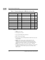
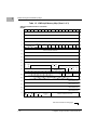
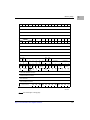
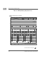
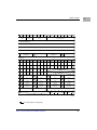
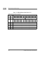
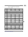
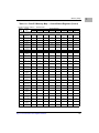
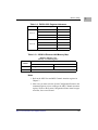
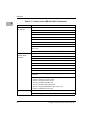
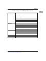
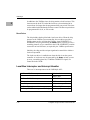
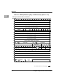
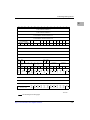
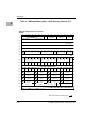
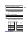
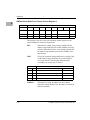
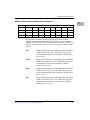
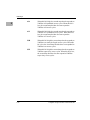
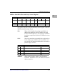
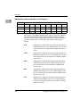
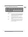
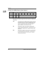
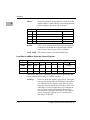
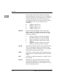
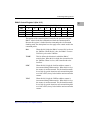
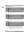
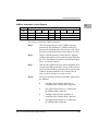
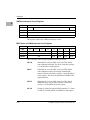
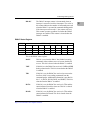
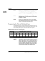
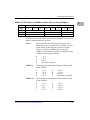
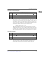
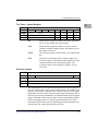
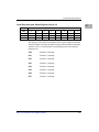
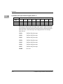
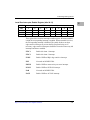
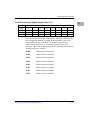
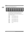
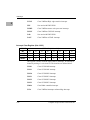
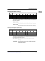
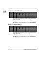
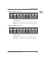
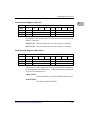
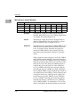
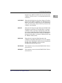
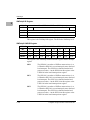
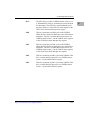
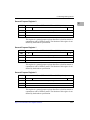
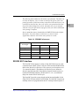
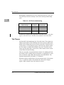
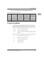
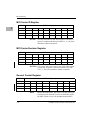
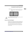
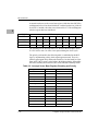
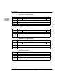
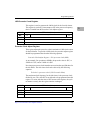
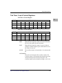
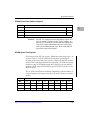
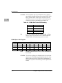
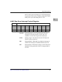
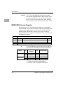
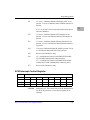
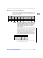
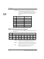
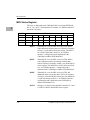
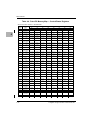
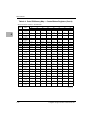
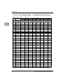
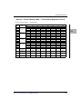
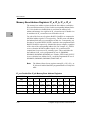
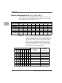
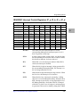
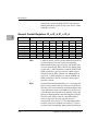
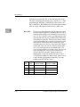
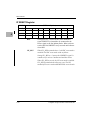
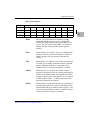
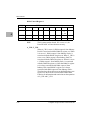
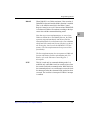
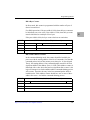
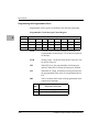
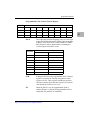
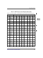
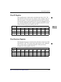
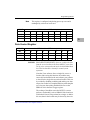
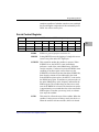
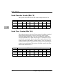
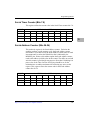
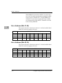
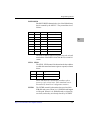
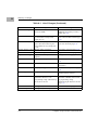
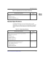
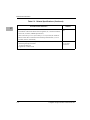
Programming Model
LSB Prescaler Count Register
This register is used to generate the 1MHz clock for the four tick timers.
This register is read-only. It increments to $FF at the processor frequency,
then it is loaded from the Prescaler Clock Adjust register.
ADR/SIZ
BIT
$FFF42014 (8 bits)
31
...
NAME
LSB Prescaler Count
OPER
R
RESET
X
24
Prescaler Clock Adjust Register
This register adjusts the prescaler so that it maintains a 1MHz clock source
for the tick timers. To provide a 1MHz clock, the prescaler adjust register
should be programmed based on the following equation:
Prescaler Clock Adjust Register = 256–processor clock (MHz)
As an example: For operation at 20MHz, the prescaler value is $EC; at
25MHz it is $E7; and at 33MHz it is $DF.
Non-integer processor clocks introduce an error into the specified times for
the tick timers. The tick timer clock can be derived by the following
equation:
Tick clock = processor clock / (256–Prescaler Value)
The maximum clock frequency for the tick timers is the processor clock
divided by two. The value $FF is not allowed to be programmed into this
register. If a write with the value of $FF occurs to this register, the cycle
terminates correctly but the register remains unchanged.
ADR/SIZ
BIT
$FFF42014 (8 bits)
23
...
NAME
Prescaler Clock Adjust
OPER
R/W
RESET
$DF P
http://www.motorola.com/computer/literature
16
3-17
3