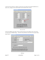
1
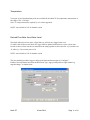
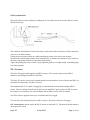
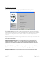
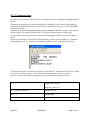
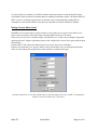
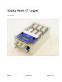
Isodaq Hawk XT Logger
User Guide
Hawk XT
6 June 2014
Page 1 of 64
Introduction to the Hawk XT
The Hawk XT is a telemetry data logger . It takes measurements from a single or a multi-parameter
sensor at regular intervals, and stores this data in internal memory.
Using GPRS, GSM or PSTN telemetry, the Hawk XT contacts a data collection system, typically once
per day, and transfers data to the data collector.
The Hawk XT can also be configured for alarms with user-specified set points. When a measurement
exceeds a set point, the Hawk XT contacts the data collector and transfers data along with an alarm
message. The alarm message is typically forwarded by the data collector as an email or an SMS message.
The Hawk XT manages power to both the modem and sensors. Internal Alkaline cells can be fitted.
Power can also be taken from an external DC source.
The Hawk XT is designed for ease of sensor connection, pluggable PCB screw terminals and glands in
the housing.
Hawk XT
6 June 2014
Page 2 of 64
Contents
Introduction to the Hawk XT
Contents
Applications
Water level
4-20mA submersible transmitter
Ultrasonic transmitter
Shaft encoder
Tipping-bucket rain gauges
Rainfall intensity alarms
Process sensors/signals, water quality
Temperature
Derived Flow Rate from Water Level
Derived Daily Flow Totals from Water Level
Hardware and accessories
Features
Specification
XVI 16-channel firmware enhancement
Sensor cards
C21
C22
C23
C24
C25
C26
C27
C31
C32
Local communications cable
Batteries
Internal battery pack
External power connection
Battery life estimation
Battery voltage alarms
Alarms
Normal alarms
Hysteresis
Configuring alarm settings
Relay
Alarm beacon suppression
Hawk XT
6 June 2014
Page 3 of 64
Telemetry setup
Access to Timeview
SIM requirements
SIM installation
Status LEDs
Telemetry introduction
Telemetry protocols - DNP3 or Modbus
Telemetry physical layer
Receiving data via GPRS
Polling or check-in
Modem power management
Time switching
Check-in calls
Dial outs
Logger configuration for Timeview
Installation
Preparation
Opening the enclosure
Removing the main board
Sensor connection
Cable preparation
SDI-12 sensors
Sensor connection
SDI-12 sensor configuration
SDI-12 Harvest commands
SDI-12 Transparent Mode
SDI-12 Channel Calibration
Setting Current Water Level
SDI-12 Sensor Management
Additional SDI-12 Sensor Information
Harvest software
Getting Harvest software
Installation
Usage
Infra-red comms
Local wired comms
Remote telemetry
Modems
Data retrieval: XDQ files
Reading the current configuration
Reading parameters only
Resetting after reading
Changing logger configuration
Group and tag specification
Hawk XT
6 June 2014
Page 4 of 64
Changing sensor type
Sensor calibration
Dial outs
Exporting data
Data File types
CSV files
Reconfiguration
Sending Commands
Monitor Comms
Upgrade Logger Firmware
Declaration of Conformity
Hawk XT
6 June 2014
Page 5 of 64
Applications
The Hawk XT helps you collect data from sensors in remote locations. This chapter describes some of the
sensors the Hawk XT is commonly used with, and lists the equipment you may need for each.
Water level
Water level can be measured with respect to an arbitrary datum without having to determine the level
above the sensor. The Hawk XT logger and software automatically determine the sensor level and apply
the datum offset when the logger is calibrated during configuration.
2.2 m Setting water level with respect to a Datum
In the example above, the water is 2.2m deep with respect to arbitrary datum D. The sensor is only d
(1.2m) deep in the water, but when the level is set, the offset to the datum is automatically applied.
Hawk XT
6 June 2014
Page 6 of 64
4-20mA submersible transmitter
Select the Water level (pressure) class from the Sensor dialog. You need to specify the 20mA value for
the sensor on the Calibration dialog. The 4mA value is normally 0, and defaults should be correct for the
rest of the parameters. Two sensors are supported. One C25 card per sensor required.
These sensors have a vent tube so that water pressure is relative to atmospheric, and barometric pressure
variations do not affect the apparent water level. An Isodaq HBH breather should be fitted to the Hawk
XT logger box to allow venting. The HBH is specified to withstand 1m immersion for 30m . When
installing, cut off the vent tube and unused conductors and about 10mm beyond the end of the outer
insulation. Do not crush the end of the vent tube.
Specific gravity (SG) increases the pressure applied by a given depth of water. A 10m transmitter would
produce 20mA in only 9.747m of saline water (sg 1.026). Specific gravity correction for the effect of
salinity causes an error of approximately 250mm.
The salt increases the weight of water, and the pressure applied by a given depth. The SG correction
reduces the full-scale depth of the sensor proportionally to the SG. The SG value must be between 1.0 and
1.03. SG values outside this range are ignored, and produce no correction. The SG used in calibration is
stored as the 4th calibration parameter and so is visible to the user investigating site calibration details. A
drop-down list of commonly used values is provided:
1.00 1.025 1.026 1.028
(Fresh)
Ultrasonic transmitter
The sensor warm-up time is long (40s) for logger-powered ultrasonic sensors because the sensor needs
time to produce a valid signal on its 4-20mA output. In some cases this time may be less, but it varies
significantly with water surface conditions.
The long warm-up time and high current consumption when the sensor is on means an external 12V
battery is preferred for all logger-powered ultrasonic applications. Select the Fluid level (ultrasonic) class
from the Sensor dialog. The only difference between the loop-powered and line-powered models is the
time required for warm-up: line powered devices are assumed to be on continuously and are given no
warm-up time.
Most ultrasonic level sensors are „smart‟, so you can configure the 4 and 20 mA air-distance values on the
sensor as well on the logger. The Harvest Calibration dialog for ultrasonics allows you to enter the air
distance 4 and 20mA values, as well as the current water level, and generates the correct offsets for
display of the data.
Hawk XT
6 June 2014
Page 7 of 64
You should set the logger for a fast storage interval like 30s, which will keep the sensor on all the time,
when you are configuring the sensor and setting the water level on the logger. After you are confident the
logger is reading the correct level, re-configure the logger to change the storage interval to (say) 15mL.
Leave the rest of the parameters unchanged.
Note that the Current Value reported in long-warmup applications is actually the last-logged value. If the
warm-up time is 4s or less, the Current Value is measured when the data file or parameters are read.
Two sensors are supported. One C25 card per sensor required.
Shaft encoder
The Hawk XT uses high-speed shaft-encoder tracking. The logger should accurately track incremental
encoders at speeds exceeding 1 revolution per second (400 count encoders).
From Harvest select the Fluid level (shaft encoder) class from the Sensor dialog.
The current water level should be entered on the Calibration dialog, and other values left as defaults. The
different models of shaft encoder vary only in their the resolution.
A C22 card is required for each sensor. Up to 2 sensor supported.
Tipping-bucket rain gauges
The tipping-bucket logging mode records the time that tips occur to the nearest 2s.
The storage interval is not used. Because data is recorded at unpredictable times, there is no way to tell
when a logger in tipping bucket mode will be full. Old data is overwritten when the storage is full.
The logger gives a red flash whenever a tip is recorded.
When the Hawk XT Display is on and you have scrolled to the Channel display, all Rainfall Tips during
that period when the display is on are treated as Test Tips. This means that they will not be recorded.
When the Hawk XT is communicating by serial or modem communications, the Display switches on but
it will continue to record tips during that period and these are not treated as Test Tips.
From Harvest select the Rain gauges class from the Sensor dialog.
Different tipping bucket sizes are available.
Note that you can also use the pulse-counting ranges from the Frequency sensor class if you want to
record the number of tips in a period and do not want to know the times of individual tips.
One C21 card required for each channel. Up to 2 sensor supported.
Hawk XT
6 June 2014
Page 8 of 64
Rainfall intensity alarms
Hawk XT loggers later support rainfall intensity alarms for channels configured for tipping-bucket
logging. Up to 4 alarms are supported for each rainfall channel. Each alarm has a set point amount in mm,
an integration period and a suppression period. The set point, integration period and suppression period
can be individually set for each alarm, so for example a rain gauge channel could have the following
alarms set:
Amount
Integration period
Suppression period
25mm
30mm
30mm
50mm
2h
6h
12h
12h
4h
4h
24h
24h
Up to 16 integration periods are supported:
10m
2h
8h
2d
15m
3h
12h
3d
30m
4h
18h
5d
1h
6h
24h
7d
These are configured via a drop-down menu on the alarms dialog box.
Up to 8 suppression periods are supported:
1h
12h
2h
18h
4h
24h
8h
48h
These also appear as a drop-down menu.
The rainfall alarms are checked at a user specified interval. All four alarms are evaluated at the same
interval. The following intervals are supported:
2m
5m
Hawk XT
15m
30m
1h
6 June 2014
Page 9 of 64
An example of a dialog box that can be used to specify the rainfall alarm parameters is shown below:
In order to evaluate each alarm, the tip record is scanned backwards (most recent tip first) and tips are
counted until a tip that is older than the integration period is found. The tip count is converted to an
amount of rainfall, then compared with the alarm set point. If the setpoint is exceeded, a rainfall alarm is
generated and the system dials out.
After the alarm is generated, the suppression time is set to the time of the alarm plus the requested
suppression period. Further alarms (for that setpoint/integration period only) are not generated until after
the suppression time.
This evaluation procedure is followed for up to 4 alarms per channel.
The alarm relay is pulsed for 1s every time a rainfall alarm is produced.
Process sensors/signals, water quality
Hawk XT loggers are widely used with water quality sensors, such as turbidity, DO and conductivity.
These sensors generally connect in two ways:
• 4-20mA current loop
• SDI-12 smart sensor protocol
Switched, 24V loop power is available via a C25 card for sensors that need it. The loop burden is 100R.
A C24 or C25 card per sensor required . Up to 2 sensor supported.
A loop isolator may need to be fitted, since the negative input for the loop is connected to the common
logger earth.
You set the units and range for water quality signals via the Harvest Process Signals configuration option.
Hawk XT
6 June 2014
Page 10 of 64
Temperature
Two types of precision thermistor probe are available for the Hawk XT for temperature measurement in
the range of -40 – 120 Deg C.
One C27 card per thermistor required. Up to 2 sensor supported.
NOTE - not available in XVI 16-channel version
Derived Flow Rate from Water Level
This mode allows the user to derive a Flow Rate (eg. m3/h) from a logged water level.
To achieve this in Harvest, the Hawk XT logger must be updated with firmware version 1.98 or later.
In order to derive a flow rate the user must know the rating equation to derive the flow „Q‟ from the level
„h‟ where Q = C(h-a) to the power of b.
NOTE - not available in XVI 16-channel version
The user should first read the logger to bring up the data and then navigate to “Configure”.
Enable a Derived Channel and select the Derivation Type “Apply lookup table to single channel e.g.
stage-discharge.” as shown below.
Hawk XT
6 June 2014
Page 11 of 64
Clicking “Edit Tables...” will present the user with the 16 point lookup table.
The input values represent water level and the output values represent calculated flow. (See below)
Once the logger has been configured with this stage-discharge derivation channel the user can set alarms
based on this flow rate. The user can then view and download flow rate data in the same way for any
standard analog parameter.
Derived Daily Flow Totals from Water Level
This mode allows the user to derive Daily Flow Rate (possibly for discharge consent monitoring) from a
logged flow rate.
NOTE - not available in XVI 16-channel version
To achieve this in Harvest, the Hawk XT logger must be updated with firmware
version 1.98 or later. To derive a daily flow rate, the user must enable another derived channel and select
the Derivation Type “Daily Flow Totals (derived from Flow Rate)”.
Hawk XT
6 June 2014
Page 12 of 64
The user must select the channel to derive from to be the “Flow Rate” channel as detailed in the above
section. This configuration will totalise the calculated flow throughout the day, continually increasing
until the end of the day is reached and the flow total starts from zero again. (See below)
Hawk XT
6 June 2014
Page 13 of 64
It is also possible to configure alarms on the Daily Flow Totals. (eg. To get an alarm when the Daily Total
Flow rises above 50m3.)
Hawk XT
6 June 2014
Page 14 of 64
Hardware and accessories
Features
Sensors can be connected to two sensor card channels, which are designed for analog or digital sensors, or
an SDI-12 port which is designed for smart sensors supporting this protocol.
Hawk XT
6 June 2014
Page 15 of 64
Hawk XT
6 June 2014
Page 16 of 64
Specification
Channels
2 sensor card channels
SDI-12 channel (8 sensor addresses and up to 8
channels with standard firmware - 16 channels
with XVI firmware enhancement, some
restrictions apply, see below)
Storage capacity
29768 16-bit readings
total for up to 8 or 16 channels
Resolution
ADC: 12-bit
Pulse input: 65000 count
Frequency: 650 Hz
SDI-12 storage: 16-bit
Communications
Direct to PC serial port
IrDA (via display board)
PSTN modem (optional)
GSM/GPRS modem (optional)
Relay
1A 30V DC latching
Contact closed when alarm present (selectable)
Remote relay on/off command
Batteries
Internal 6 x D Alkaline
External 12V lead-acid or 9-24V DC supply
Fittings
4 M16 glands (cables 3.5–8mm dia)
1 External serial comms connector
1 Tapped hole for HBH breather
1 PSTN telephone lead (with PSTN option)
1 GSM aerial TNC socket (with GSM option)
Dimensions (mm)
Hawk XT
W 160
6 June 2014
Page 17 of 64
H 240 (270 with glands)
D 90
Construction
Grey polycarbonate with gasket.
Transparent lid fixed with 6 quarter-turn fasteners.
4 holes for wall-mounting
Protection
IP65
Operating limits
-40–70 deg C, 0–100% RH
XVI 16-channel firmware enhancement
XVI is special version of the logger firmware which can be factory installed, or applied in the field with
Harvest. It expands the channel capacity of the logger to up to 16 channels total. It does so by reducing
the size of the look-up tables used for calculating engineering values in each channel. With the XVI
firmware, only linear correction (with offset) is possible. Curves cannot be used.
In practice this means that with the XVI firmware, derived channels are not available, and neither are
rating tables or curved corrections for thermistors. Otherwise, usage is identical to the standard 8 channel
firmware.
Sensor cards
You must ensure that the sensor card you select is correct for your application.
Inserting the wrong sensor card can damage your sensor or the card.
Harvest software indicates the correct sensor card to use when you select a sensor type.
Sensor cards allow the Hawk XT to be quickly reconfigured for different applications, and reduce costs
by eliminating expensive circuitry if it is not required for an application.
This section contains background information on how sensor cards work.
Sensor cards don‟t contain any „intelligence‟ - they don‟t pass configuration information to the logger.
You must do this via the Change Sensor option in Harvest. The logger module has no way of knowing
which sensor card is fitted unless you tell it via the software.
Most sensor cards contain protective circuitry to help the logger survive a lightning strike or „powercross‟ when power is accidentally connected to a sensor input.
Sensor cards are numbered sequentially, starting at C21, with some gaps. In some cases, a second
number, the card version appears on the label on the white plastic cover. Refer to the individual card
descriptions for significant differences between versions.
Hawk XT
6 June 2014
Page 18 of 64
C21 - Tipping bucket rain gauge or digital input
C22 - Incremental shaft encoder
C23 - 0-2.5V input, high impedance, switched 2.5V potentiometer excitation output
C24 - 4-20mA input, 100R shunt resistance, no power for sensor
C25 - 4-20mA input, 100R shunt resistance, switched 24V power for sensor
C26 - 0-50V input, input impedance 250K
C27 - Temperature via 5K precision thermistor
C31 - 4-20mA input, 100R shunt resistance, switched 12V power for sensor
C32 - Frequency input for NRG model 40 anemometer
C21
The C21 card is a pulse input card. Terminal SA is connected to logger ground, and normally goes to one
end of the switch in the sensor.
SB is the high-speed input, which should be used with clean pulse signals which don‟t have contact
bounce.
SD is the „debounced‟ input - this input is filtered so noisy switch closures will not cause multiple pulses
to be recorded. The debounced input should not be used for brief pulses, such as those from rain-gauges,
because the pulse may be too short.
Both SB and SD have internal pull-up resistors so they can be used with volt-free contacts. Opencollector outputs are also suitable: use SA because these signals have no contact bounce.
Both inputs pass into Schmitt triggers on the main logger board.
The maximum pulse frequency into SA is 650Hz, and into SB is 10Hz. Pulse capacity is 65000 counts per
reading.
C22
The C22 card is a specialized card for incremental (quadrature) shaft encoder driving. Only shaft encoders
designed for high-speed pulsed power work with the C22 card.
SA is connected to the logger ground, and SD supplies narrow pulses of power (at appoximately 1kHz) to
the shaft encoder.
Inputs SB and SC receive the quadrature signals from the shaft encoder and route them to Schmitt triggers
on the main logger board.
The C22 card has been recently redesigned to support fast tracking of shaft encoders. The redesigned
parts are labelled C22-5. If you have C22 cards with lower numbers (C22-1 through C22-4) please
contact your Isodaq agent.
Hawk XT
6 June 2014
Page 19 of 64
C23
The C23 card is used for 0-2.5V inputs, which should be connected to SB. This is a very high impedance
input, in the order of 10 , and will not significantly load 12 circuits that remain within the 0-2.5V range.
Note that signals that exceed 0-2.5V will be clamped to the logger supply voltage or ground by protective
circuitry.
A switched 2.5V reference output is available on SC. The reference output is useful for energizing
potentiometers. The output is also protected by overvoltage circuitry.
SA is the signal ground.
C24
The C24 card contains a 100 precision resistor. 4-20mA current loop signals will produce 0.4-2.0V across
this resistor when the loop is connected across terminals SA and SB.
An indication of the loop current can be obtained by connecting a voltmeter across SA and SB and
multiplying the voltage by 10 to get the loop current in mA. When measuring in this way, note that the
total current shunt resistance from SA to SB is greater than 100 because of protective circuitry - the
logger accuracy is not affected by this.
C25
The C25 card contains the same current shunt resistor as the C24, but also contains a power converter to
boost the 6V logger supply to 24V, 80mA, in order to drive loop powered 4-20mA sensors. Sensors
should be connected between SD (+) and SB(-).
The power convert is only on when the sensor requires power, but because the power conversion is
inefficient, significant battery drain can occur with applications using C25 cards. The power converter in
the C25 card should never be connected to capacitive loads (greater than 1uF ) or damage to the sensor
card may result.
C26
The C26 card contains a precision voltage divider for measurement of voltages up to 50V across terminals
SB (+) and SA (-). Input impedance is 250k .
C27
The C27 card is specifically designed for driving a 5K precision thermistor for temperature measurement.
The thermistor must have a Beta value of 3892 (material 3). Suitable thermistors are available from your
Isodaq agent.
Hawk XT
6 June 2014
Page 20 of 64
C31
The C31 card is identical to the C25 card, except that it provides a nominal 12V output instead of 24V. It
is designed for powering 4-20mA sensors that have supply voltage restrictions.
C32
The C32 is a special frequency input card for use with NRG anemometers and other frequency output
devices where the signal is small and centered about 0 volts.
The Hawk XT Relay is for sampler or warning beacon use only; it must not
be used to control the measured parameter or in any other part of a control
system.
Local communications cable
To read and configure the Hawk XT locally, you will need to order one of these communications cables:
CBL-HWK-EXT local serial cable (RS-232)
CBL-HWK-USB local serial cable (USB)
The CBL-HWK-USB has a built-in USB to RS232 converter, and works with our full range of loggers. It
is ideal for laptops without built-in serial ports.
The CBL-HWK-USB requires drivers , which are normally pre-installed on modern PCs. If not, drivers
can be downloaded from:
www.ftdichip.com/Drivers/VCP.htm
Hawk XT
6 June 2014
Page 21 of 64
Batteries
The Hawk XT can be powered by both an internal battery pack and an external power source.
Current is drawn from whichever source has the higher voltage. When both the internal and external
supplies have fallen to the same level, power is drawn from both.
Internal battery pack
The Hawk XT internal pack uses 6 LR20 „D‟ Alkaline cells on the main board.
The pack has a nominal voltage of 9V, and can be used until the pack voltage drops to 6V (1V per cell).
Alkaline cells become unstable when they reach 0.8V per cell, so they must be changed before they reach
this level.
Alkaline batteries systems show a drop in voltage as their capacity is consumed. The drop is not linear the voltage drops quickly at first, then levels out.
Use only Alkaline D cells for the internal pack - never fit rechargeables, Lithium batteries or other types
in their place.
The cells should all be oriented in the same direction, with the positive end down, as indicated by the
markings on the main board.
When you replace the internal batteries, you should replace them all at once, with cells of the same make
and from the same batch. You should always fit the internal pack, even if the Hawk XT is primarily
powered from an external source. It provides a useful backup and prevents loss of system time accuracy
when the external power source is interrupted.
Hawk XT
6 June 2014
Page 22 of 64
Hawk XT batteries and external power
You can run the Hawk XT on external power when changing the internal batteries with no loss of time
accuracy.
If you change the internal pack without and external supply connected, you should reset the Hawk XT
afterwards to keep the clock accurate.
External power connection
A 12V lead acid battery, or the output from a solar regulator or other power supply can be connected to
the EXT POWER terminals
Hawk XT
6 June 2014
Page 23 of 64
Battery life estimation
Hawk XT battery life is difficult to estimate because it depends strongly on the following:
• The modem duty cycle for GSM modems. Time switching should be used to limit the proportion of the
time the modem is on.
• Sensor current drain. Some sensors draw continuous current, and others have long warm-up
requirements. Both these factors will significantly decrease battery life.
• Alarm activity. Sites with many alarm dial-outs will have shorter battery life than those that rarely dial
out.
Harvest software provide a battery life estimate as part of the configuration procedure that takes the
modem duty cycle and sensor current into account.
Battery voltage alarms
The battery voltage alarms are tested at every 15m. The Hawk XT will dial out automatically if a low
battery is detected, provided
• The Dial Numbers are correct
• The Dial Condition on the Battery tab of Harvest is set to “falls below setpoint”
The battery voltage normally varies during operation as the current drawn by the system changes, so a
default hysteresis value of 1.0 V is used to prevent alarm re-triggering.
By default, a set point of 6.0V is used for internal 6-cell packs and 10.0V for external 12V batteries.
Alarms
Hawk XT loggers are frequently used for monitoring water levels and generating alarms if thresholds are
exceeded. Other parameters measured by Hawk XT can also be monitored for alarms.
Typical uses are for alarm forwarding in emergency situations, such as flood warning, when alarm
messages are managed by a telemetry server at a central location.
Telemetry servers supported by the Hawk XT are listed in section 7 . An alarm relay can be used for
triggering warning beacons, signs and for sampler triggering. This is described in section 5.3 .
Hawk XT telemetry loggers are typically used for alarm purposes, so that alarm messages can be
forwarded to central locations.
Hawk XT
6 June 2014
Page 24 of 64
Normal alarms
Up to 4 set points for each channel can be tested against the measured value. If the test indicates an alarm
has occurred (either above or below the setpoint), the following actions take place:
1. Telemetry loggers dial-out to a series of up to 4 user-specified phone numbers.
2. GPRS loggers may begin checking-in more frequently, if configured to do so.
3. The alarm relay is closed
In telemetry systems, alarms cause the Hawk XT to power the modem and check to ensure the modem
has a signal and is registered before dialling out.
Hysteresis
Hysteresis can be used to stop multiple alarms when the measured value is hovering near a set point.
Here, the hysteresis parameter is used to temporarily adjust the set point once the alarm is set. For
example, assume an alarm set point of > 65% with hysteresis of 10%:
Hysteresis on alarm set points
1. The signal rises to 65% and the alarm is triggered.
2. Hysteresis reduces the setpoint by 10% to 55%.
3. The signal hovers around 65%, repeatedly crossing the old alarm set point. No alarms are produced.
4. Finally the signal falls to below 55%. The alarm is cleared and the set point is restored to >65%.
Hysteresis can be disabled by setting this parameter to 0. Each of the first 4 set points has independent
hysteresis, but the hysteresis value is common.
Hawk XT
6 June 2014
Page 25 of 64
Hysteresis and relay control
In the above example, two alarm „zones‟ have been set, the first triggering an alarm used to dial out a
telemetry warning, the second being set to close the relay contact (initiating an auxiliary function like a
warning beacon). Note that for both alarms, a hysteresis value of 0.1m has been applied, which is used to
prevent any spurious alarm conditions.
In the case of the upper level alarm, the relay will close at the measured value of 0.8 and open at the
measured value of 0.7. Note that for the data shown on the graphical plot, no alarm conditions have been
reached.
Hawk XT
6 June 2014
Page 26 of 64
Configuring alarm settings
You must read the data or parameters from a Hawk XT outstation with the Harvest software before you
can configure the alarms.
The Alarms tabbed dialog is displayed by the Alarms button on the Outstation Parameters screen.
If this button is “greyed out”, it means that telemetry is not enabled in the Hawk XT system - contact your
Isodaq agent.
Relay
The Hawk XT has a latching relay for sampler and alarm beacon triggering. The relay contacts are rated
at 1A 30V DC.
The relay contacts are on the green terminal block marked RELAY.
The relay contacts are operated on the following conditions:
• For enabled level alarms with the relay box ticked , the relay closes when the alarm occurs, and opens
when the alarm condition ends.
• For all enabled rainfall intensity alarms , a 1-second relay closure occurs when the alarm is detected.
• The relay closes when a relayOn command is sent by Harvest either locally or via telemetry. The relay
opens with a relayOff command.
Alarm beacon suppression
If Hawk XT relay is used to trigger an alarm beacon and/or warning sounder, the logger front panel
switches can be used to open the relay and suppress the warning flash/sound.
The relay will remain open until the next alarm, so this feature is a safer way to silence a beacon than with
an external switch. External switches must be switched on again after the alarm clears, and it is easy to
forget to do this.
Telemetry setup
This section describes how to setup your Hawk XT for use with Timeview Telemetry, the web-based data
collection and alarm forwarding service operated by Hydro-Logic.
Note that if you have ordered your Hawk XT with a Timeview Telemetry package, it will most likely be
already configured correctly and tested.
You should still confirm that the system is correctly conifigured and communicating properly before you
go to site, however.
Access to Timeview
Hawk XT
6 June 2014
Page 27 of 64
Before you start, you need a account on www.timeview2.net .
You also need a logger profile on your account for every logger connected to Timeview.
Accounts and logger profiles are created by the Timeview administrators, once you have ordered the
service.
You will not be able to see your data or receive alarms until these steps have been completed.
Once you can log-in to Timeview and see your logger profile, you can configure your logger to connect to
it. If you are ordering Timeview Telemetry for a logger you already have, please ensure that you specify
the following information with the order
1. Account name
2. Logger serial number
3. Group and Tag from logger configuration
If you are ordering a new logger for use with Timeview, you can omit the logger serial number from the
above list.
SIM requirements
Clients within the UK may arrange SIMs to be supplied with part of the Timeview package. This will
ensure they are correctly configured to access the data collection server.
If you are supplying your own SIM for a Hawk XT, please ensure that the SIM meets these requirements:
The SIM must be
• GPRS enabled, with internet connectivity. A monthly usage of 1MB is sufficent for most sites with daily
data check-in. Fixed-IP SIMs are generally not necessary.
• Data Enabled - it must support GSM CSD data. This is important even if the site to be used with GPRS.
Record both the voice and data numbers of the SIM – they are usually different.
• SMS enabled, especially for incoming messages. Outgoing message are sometimes useful but not
essential.
• Free from password protection . Test the SIM in a normal phone to ensure there is no password request,
and if necessary disable the password via the phone‟s security settings.
Hawk XT
6 June 2014
Page 28 of 64
SIM installation
Hawk XT SIM fitting
1. Open the lid
6. The SIM holder is on the front of the main board. Open it by sliding the metal bar to the right and
lifting the hinged plastic holder.
7. Slide the SIM into the plastic holder, with the contacts down and the cut corner pointing outwards
8. Fold the holder down, and slide the metal bar to the left to lock it.
Hawk XT
6 June 2014
Page 29 of 64
Status LEDs
The telemetry status of the logger is indicated by two status LEDs.
The Red and blue LEDs are used in combinations shown below
Single Blue: Modem OFF, Normal Logging
Double Blue: Modem ON, Good Signal, Normal Logging
Blue/Red: Modem On, No Signal, Normal Logging
Rapid Blue flashes: Modem switching On
Solid Blue: Comms Active, Waiting To Receive
Solid Blue with Red Flashes: Comms Active, Transmitting Data
Telemetry introduction
This section summarizes the telemetry methods used, and how telemetry is configured.
Hawk XT
6 June 2014
Page 30 of 64
Telemetry protocols - DNP3 or Modbus
The telemetry protocol specifies the exact message format used to transfer data from telemetry loggers.
It‟s not sufficient to specify “GPRS”, since this does not state the message format.
Telemetry protocols require two-way communications, and are designed so that error-free data delivery is
guaranteed.
The Hawk XT supports two telemetry protocols: A modbus ASCII scheme for transfer of alarms, time
series data and configuration, and DNP3, a powerful industry-standard SCADA protocol. These protocols
are used to communicate with the following telemetry servers:
Telemetry server
Protocol
Isodaq Harvest
Modbus
Isodaq Timeview
Modbus
Isodaq Timeview Virtual Appliance (TVA) Modbus
Isodaq XDQ Server
Modbus
Serck SCX
DNP3
CSE Servelec Scope-X
DNP3
Kisters SODA
Modbus
Notes
1
2
5
3, 4
3, 4
3
Notes:
1. Suitable for manual dialling only. Necessary for logger configuration. Not suitable for receiving alarm
calls.
2. Simple web-based collection; no software needed for browsing data at the client.
3. Driver and version upgrades may be required from your SCADA supplier to enable DNP3 support.
4. The DNP3 Device Profile Document for the Hawk XT is available from your Isodaq supplier. A
firmware upgrade may be required to support DNP3, but this can be installed remotely over GSM or
locally via Harvest without removing the logger from site. Please specify you require DNP3 when you
order your loggers by adding the -DNP3 option to the order code.
5. The Timeview Virtual Appliance (TVA) provides the functionality and exibility of Timeview, which is
the core of Isodaq alarm and data forwarding systems. Essentially it is a GPRS-only FEP with no
hardware. TVA is only suitable for GPRS applications, since there are no modems supplied with it.
TVA runs under any MS or other operating system that supports VMware Virtualization Products. TVA
can also run under native VMware infrastructure products.
Telemetry physical layer
Isodaq Telemetry Loggers can use the same protocol over several different physical layers .
Hawk XT
6 June 2014
Page 31 of 64
The physical layer and the protocol are independent - the same protocol can be used over several physical
layers.
Hawk XT
GPRS
GSM (CSD)
PSTN
•
•
•
Hawk RT
Frog RX
•
•
•
•
Receiving data via GPRS
GPRS data collection uses no modem at the receiving end. Data comes in directly over the internet - the
Hawk XT “dials out” to a URL (a web address). Setting up a web address to receive GPRS calls requires
IT expertise, and depends on the network configuration at the organization hosting the data collector.
Unless fixed IP SIMS are used, only check-in mode (logger originated calls - see below) is supported for
GPRS. Loggers can still be polled via Harvest and a modem if the CSD data number of the SIM is
known.
Polling or check-in
There are two methods of retrieving data from telemetry loggers:
• Polling, where the data collector originates calls to outstations
• Check-in, where the outstation originates calls to the data collector
Polling has advantages where the logger must be contacted by the data collector on demand.
Check-in has advantages of lower power consumption, and of daily test of potentially critical alarm calls.
Isodaq Telemetry Loggers support both methods, although check-in is generally preferred for reasons
outlined in the following sections.
Modem power management
GSM/GPRS modems use significant power when they are left switched on so the logger can receive calls.
Power is mainly consumed by the radio receiver, and is higher in weak signal areas.
For extended battery life, the modem should be switched off for most of the time.
Time-switching is one way of doing this, where the outstation can be contacted during several „windows‟
of time where the modem is powered. However, this still means that the modem can be on for hours each
day, waiting for calls.
It can be difficult to contact an entire network of outstations during the time-switch window, leading to a
complex system of different windows for different parts of the network.
For good battery life, we recommend the modem is left on for at most 15m per day. If you leave the
Hawk XT
6 June 2014
Page 32 of 64
modem on for hours per day, you will have significantly reduced battery life.
Note that the Frog RX uses a GSM modem with a special low power mode which greatly extends the
battery life when the modem is on.
Time switching
Time switch times must be specified in the format HHMM (eg 2210 for 10:20 pm).
Specify them in normal time, not daylight saving time, so you may need to subtract an hour if you are
configuring the outstations in the summer. Notes on modem time switching:
• If the remote system loses power, the ON and OFF times will be incorrect and you will not know when
the remote modem is switched on. The error will not be the same as the duration of the power failure. It
can only be corrected by reconfiguring the time-switch settings, which may be difficult if the site is
remote and modem is off!
• The modem will switch on and remain on for 10 minutes after a Hawk XT is powered up, after an alarm,
or after it is dialled for a (polled) data collection. You can force the modem to switch off after one of
these events with a ModemOff command from Harvest either locally or remotely.
Check-in calls
To avoid the problems with time-switched polling, the Hawk XT can be programmed to „check-in‟ every
day, automatically switching on the modem, dialling out, waiting for the call to be answered, then
powering down the modem. This method allows the modem to be powered for the shortest possible time.
The check-in call is virtually identical to an alarm call, except that the message does not contain an alarm
trigger.
This is an important feature for enhanced reliability - it is a daily self-test of behaviour that becomes
critical in alarm conditions. You do not get this with systems that rely on polling for data collection.
Outstations will attempt to check-in at a random times between the two specified check-in times.
For a small network of outstations, the check-in times can be reasonably close together, for instance 30m
apart.
Larger networks can allow all day to check-in, with times of 0030 to 2330 specified.
If either check-in time is set to 0000, the check-in feature will not operate.
Note times must be specified in normal time , not daylight saving time, so you may need to subtract an
hour if you are configuring them in the summer.
Daily check-in can be used along with time switching. A short time-switch period can be set after the
latest check-in time in case the outstation needs to be contacted for reconfiguration, or in case the checkin was unsuccessful.
Dial outs
The Hawk XT must be set to dial specified numbers on alarms and check-in events.
The Hawk XT uses a dual-master dialler that supports check-in calls and alarms to up to two data
Hawk XT
6 June 2014
Page 33 of 64
collection (master) systems.
Only use Dial Numbers 1 and 2 if you are checking in to a single data collection system.
The dial-out sequence is as follows:
1. The modem is powered-up (or power-cycled if it was already on). This is shown by a series of rapid
blue flashes on the status LEDs.
2. After power up, the modem is given 2m to get at GSM signal. The modem is polled every 10s to see if
there is a signal and that it is registered with the network. As soon as both conditions are satisfied, the
dial-out procedure (see below) is triggered.
If no signal is obtained after 2m, the modem is power-cycled and there is a further 2m wait. This
procedure is repeated 3 times in total. If there is no signal after the 3 cycles, the system waits 30m before
trying the same procedure again. The 30m wait procedure is repeated 3 times in total.
3. During the dial-out procedure, one of the stored dial-numbers is sent to the modem, prefixed by an
ATD command. The call is given 2m to be answered. Once the call is answered, the master system issues
commands to stop subsequent dial-outs to the current number pair.
If there is no answer, the modem is power-cycled and the system repeats the previous signal-waiting
procedure.
Each number is tried 3 times in total. Up to 2 numbers can be specified for each master. When each
number has been tried 3 times, the system waits for 30m, then the entire procedure is repeated.
The dial numbers (1–4) are tried in the the following sequence:
Master no 1
111222
→
Master no 2
333444 →
111222
→
333444
111222
→
333444
→
30m break
←
30m break
←
If an alarm, check-in or dial-out command occurs during the 30m break, the sleep ends and the dialler restarts as fresh. If they occur when the dialler is active, waiting for signal or waiting to be answered, they
do not cause a dialler re-start.
This is so that multiple alarms that occur rapidly do not disrupt the dialler timing.
If you are only dialling one master, use either numbers 1 and 2 or numbers 3 and 4, but not all four or you
will get duplicate calls for each alarm or check-in.
Logger configuration for Timeview
Important: Do this before you go to site. Everything should be tested and working before you leave for
site.
Hawk XT
6 June 2014
Page 34 of 64
1. Read the logger with Harvest, right-click on the plot that appears and select Configure.
2. Select the Dial Numbers tab. For field 1, enter “tva.webhop.org”, and in field 2, enter
“tva2.webhop.org”. These are two distinct servers in geographically separate locations - data can go to
either, although the first site has priority.
Dial Numbers for Timeview
Hawk XT
6 June 2014
Page 35 of 64
3. Select the Time Switch tab. Configure a check-in time of typically between 0600 and 0800 hours as
shown. Also, configure a time switch window between 1000 and 1005, as shown:
Timeswitch tab
4. Select the GPRS tab. The APN, Username and Password must suit the SIM you have in the logger.
You can use the Get GPRS Settings. . . check box to help find these. Set the Server Port to 8443 . Select
Daily Check-in.
GPRS tab
Hawk XT
6 June 2014
Page 36 of 64
5. Now press Next, and follow the rest of the steps to write this configuration
to the logger.
6. Test the configuration by using Harvest. Select “Send Command to Logger” then “Trigger Dialout
to Master Station”. Ensure the you set the option “Monitor Comms After Command is Sent”.
Watch the Monitor Local window. If all is well, you should see lines labelled “modbus packet” which are
being sent to Timeview.
Monitor comms window after a successful transfer
If, after a few minutes, you don‟t see any modbus packets, highlight, copy and paste the contents of the
Monitor Local window to an email and send it to:
[email protected]
We may be able suggest solutions to the problem once we see the log.
Hawk XT
6 June 2014
Page 37 of 64
Installation
Preparation
As far as possible, the Hawk XT should be prepared and checked before you go to site. In particular, the
following should, if possible, be done on the bench:
• Fitting batteries
• Installing and testing the SIM (GSM modems only)
• Testing sensors
Opening the enclosure
Open the box lid, which is secured by six quarter-turn fasteners. Do not unscrew the display switch
covers; the display should remain attached to the lid.
Unplug the display ribbon cable where it joins the main board by pulling it out.
Place the lid and display to one side.
Removing the main board
You need to remove the main board in order to fit a SIM, or if the board requires servicing.
The main board is secured on steel mounting posts by the lid of the box. No tools are needed to remove
the board, and there are no screws to lose or drop. Follow these steps, referring to the diagram below:
Hawk XT
6 June 2014
Page 38 of 64
1. Remove the batteries from the internal holder
2. Unplug any terminal blocks which are connected to sensors and external power
3. Unplug the GSM antenna, if fitted
4. Pull the end of the main board upwards by grasping the black plastic battery holder side clamps (A),
using pressure on the box edge to pull the main board off the mounting posts (B)
5. Hook your fingers under the main board terminal blocks (C) and pull the board off the mounting posts
(D), again using pressure on the box edge to help
Removing the Hawk XT board
Hawk XT
6 June 2014
Page 39 of 64
Sensor connection
Sensor Wiring depends on the application. Harvest software provides wiring information when you select
a sensor type.
The sensor wires should be connected to terminals labelled SA to SD (channel 1 or 2) according to the
information on the sensor card itself, or displayed by Harvest software.
Screen connections should be made to terminal SA, which connects to the Hawk XT ground when the
sensor card is in place. The sensor is only powered once a sensor card in place.
Unused sensor card channels need not be fitted with sensor cards. SDI-12 sensors connect to the SDI-12
port on the main Hawk XT board.
Hawk XT
6 June 2014
Page 40 of 64
Cable preparation
Strip back 100 mm of outer insulation (including any foil or braided screen) from cables that are to enter
the Hawk enclosure.
The conductors should either be fitted with crimps or tinned with solder so that neat, reliable connections
to the screw terminal are made.
Unplug the green connector block to simplify attaching the sensor wires to the screw terminal.
Pass the cable end in though a gland near the terminal block, so that the outer insulation is just visible on
the inside of the gland, but does not extend into the Hawk box.
Tighten the gland gently using a wrench - finger tightened glands are not tight enough. Fit blanking plugs
to all unused glands.
SDI-12 sensors
The Hawk XT supports data logging from SDI-12 sensors. These sensors conform to the SDI-12
Standard, a Serial-Digital Interface at 1200 baud.
The Hawk XT can also convert serial communications from the modem or local serial port into SDI-12 to
communicate transparently with SDI-12 sensors.
The standard Hawk XT is capable of logging up to 8 data channels and can handle multiple SDI-12
sensors. These 8 available channels can be split between non-SDI-12 inputs and up to 8 SDI-12 sensors.
For example, you could have one 4-20mA channel and one SDI-12 sensor with 7 parameters.
The XT16 firmware upgrade allows up to 16 channels total to be logged.
You can selectively enable parameters on SDI-12 sensors - they do not all need to be logged.
12V external power must be used with SDI-12 sensors on the Hawk XT. The internal Alkaline batteries
do not power the sensor.
Hawk XT
6 June 2014
Page 41 of 64
Sensor connection
The data and ground connections to the SDI-12 sensor should be connected to the marked terminals on
the Hawk XT main board.
The SDI-12 PWR connection is linked to the external power input. An external 12V supply must be used
with SDI-12 sensors.
SDI-12 sensor configuration
The SDI-12 tab controls which parameters are logged from an SDI-12 sensor. Select the required sensor
by via the Change Sensor checkbox. Multiple SDI-12 sensors can be added from the Add Sensor box on
the SDI-12 tab.
When there are multiple SDI-12 sensors connected to the Hawk XT the sensors must have unique SDI-12
addresses: one sensor could have address 0, the second address 1, etc. The SDI-12 address can be entered
in the SDI-12 tab. You can request and set the sensor address with Harvest via the Advanced Logger
Options/SDI-12 option.
Hawk XT
6 June 2014
Page 42 of 64
SDI-12 Harvest commands
The Harvest Start Wizard/Advanced Logger Options/SDI-12 has the following features:
SDI-12 Request Address Gets the SDI-12 address of the connected sensor. Only one sensor should be
connected to the Hawk XT when you run this command SDI-12 Change Address Specify the old address
and new address to change address of sensor. Beware of address con icts when multiple sensors are
connected.
Request Sensor ID - Request Sensor ID string from SDI-12 sensor. This normally contains details of the
sensor make and model number.
Request Measurements from Sensor - This command sends the Retrieve Measurement SDI-12
commands to the sensor. e.g. aM!, aC!, aC1!, aC2! and retrieves the data using the aD0!, aD1!, etc
commands. This will continually loop through retrieving measurments and printing the values to the
screen
User Defined SDI-12 Command - This feature lets you specify a command to send to a SDI-12 sensor.
SDI-12 sensors often have additional commands that let you set ranges, trigger a wiper, etc.
Manage SDI-12 Sensor List - Lets you add, edit or remove a list of User-Defined SDI-12 sensors.
Hawk XT
6 June 2014
Page 43 of 64
SDI-12 Transparent Mode
The following is a guide to using the Hawk XT in transparent mode for calibrating and debugging SDI-12
sensors.
Transparent mode allows you to send extended SDI-12 commands to sensors. Run a terminal program
such as Microsoft (R) HyperTerminal. Connect the PC to the Hawk XT using a serial cable CBL-HWKEXTor using infrared.
Open the port in the terminal program using the settings 9600 baud, 8 data bits, no parity, 1 stop bit and
no flow control. You can check that the Hawk XT is properly connected to the PC by pressing
the Up or Down arrow keys several times. This will scroll through the Hawk XT System and Channel
values.
In order to put the Hawk XT into SDI-12 transparent mode, you have to send a number of „!‟ characters.
After typing about 4 or 5 „!‟ characters, you should see “SDI-12 Active” on the Hawk XT display.
You can now send SDI-12 commands to the sensor via the Hawk XT. When the Hawk XT detects around
10 seconds of no SDI-12 activity, it will switch off the transparent mode. You have to send it „!‟
characters to put it back in SDI-12 transparent mode. A typical session might be as follows :
?! 0
Request sensor address
Response - address is 0
0I! 013NEP395-SN82181
Request sensor ID
0XR3! 0
Change range
0XW !
Request wipe
Hawk XT
6 June 2014
Page 44 of 64
SDI-12 Channel Calibration
Each individual channel for an SDI-12 sensor has its own calibration settings. You can change the Range
of any of the channels by selecting the Calibration checkbox for the appropriate channel. For example, the
Range of values for a temperature channel may be From -5 DegC to +45 DegC.
It is important to note the „Range From‟ and „Range To‟ values are not used to scale the values coming
back from the sensor. They are simply used to define the range of acceptable values from the sensor for
that particular parameter.
Values outwith that range are recorded on the logger as Out Of Range Low or High and will appear as a
gap on the graph for that parameter.
The XX logger does not store SDI-12 data directly as oating point values. To increase space efficiency it
logs data as unsigned integers instead of oating point values and it maintains lookup tables to convert
from the unsigned integer values back to oating point engineering values.
This efficiency results in greatly increased data storage on the logger but the nature of the conversion
means that the resulting engineering values have a certain resolution based on the range of values
that are possible.
For example, consider an SDI-12 level sensor that returns a temperature value in the range -5 DegC to
+45 DegC. This range of 50 degrees C is converted to an unsigned integer between 0 and 65529. This
gives a resolution of 50/65529 = better than 0.001 DegC (this has been rounded to the 3 decimal places
specified on the logger channel).
The Harvest software displays this resolution in the SDI-12 Calibration settings for each parameter, as
below. The resolution value will update automatically when you change the Range From and Range To
values.
Hawk XT
6 June 2014
Page 45 of 64
It is also possible to set alarms for an SDI-12 channel in the same manner as with the Frog RX sensor
card channels. Some sensors have channels that have additional calibration options. The Analite NEP395
SDI-12 sensor is a turbidity sensor that has a wiper that can be initiated through extended SDI-12
commands. For the Analite NEP395 sensor the wipe command can either be enabled or disabled.
Setting Current Water Level
With SDI-12 level sensors there are often a number of ways that you can set the Current Water Level.
Some sensors such as the Gems 9500 simply return the depth of water over the sensor.
In this case you can use the ”Calibrate using Current Water Level” in Harvest by reading the logger then
opening either the Configure right-button option or the Configure/Set Current Value option from the Start
Wizard menu.
From the SDI-12 Tab, choose the channel for the level sensor, then select Calibration.
Enter the Current Water Level, ensure Calibrate Using Current Water Level is checked and pick either
above or below datum, then complete the wizard sequence to configure the logger.
If locally connected (i.e. not via a modem) Harvest will interrogate the sensor via SDI-12 commands to
read the current level (Harvest 3.1.0 or later).
Hawk XT
6 June 2014
Page 46 of 64
If connected via telemetry (or using an older Harvest), the last-logged value will be used as the current
level.
When the logger records the next time, the level will be offset to the requested datum.
Alternatively, some sensors let you set the current water level using extended SDI-12 commands and the
adjusted values will then be returned by the sensor without need for the Hawk XT to do any further level
adjustment: the Ohmart Vega Vegapuls Radar Level Sensor lets you set the Water Level using the
axSS+n! SDI-12 command where ‟n‟ is the current stage value.
For the OTT RLS Radar Level Sensor, it returns the distance from the sensor to the water surface. It is
possible to record Stage above datum values from the RLS sensor by selecting the Below Datum option in
Harvest and entering the Current Water Level.
SDI-12 Sensor Management
The Manage SDI-12 Sensor List option lets the user maintain their own list of supported SDI-12 sensors. This means that for advanced users it is no longer necessary
to request an updated SDI-12 sensor file in order to support a particular SDI-12
sensor that is not presently in the supported list.
Hawk XT
6 June 2014
Page 47 of 64
Harvest software will continue to come with a maintained list of supported SDI-12 sensors in the sensor
file XdqSens.xml . The SDI-12 Sensor Manager in Harvest uses an additional User-Defined SDI-12
sensor library stored in the sensor file UserSdi12Sensors.xml .
To add a new SDI-12 sensor that is not currently supported in the XdqSens.xml SDI-12 list, select User
Defined SDI-12 Sensors and then Add New SDI-12 Sensor.
Hawk XT
6 June 2014
Page 48 of 64
To add the new SDI-12 sensor you need to define the Sensor Description and short identifier for the
sensor along with the SDI-12 Output Order that the sensor returns. You may need to refer to the SDI-12
Technical Documentation for the sensor to determine this.
Hawk XT
6 June 2014
Page 49 of 64
When adding a parameter, you need to define the Description and units (both 8 characters maximum).
The parameter range also needs to be defined so that the optimum scaling can be applied on the logger to
get the best possible resolution. There are also options to edit or remove existing User-Defined SDI-12
sensors.
Additional SDI-12 Sensor Information
The Wipe channel for the Analite NEP395 has a special type of calibration that lets you select the Wipe
interval. The Wipe command is performed and the result is recorded according to the Wipe interval
setting. The wipe status of 0, 1 or 2 is recorded. The Wipe interval can be set to be a multiple of the SDI12 logging interval: it could have a wipe interval of 12hrs for 15 min SDI-12 logging. The
Wipe will appear as a separate channel when plotting the data from the Analite NEP395. To disable the
Wipe, deselect the Wipe channel from the SDI-12 tab.
Hawk XT
6 June 2014
Page 50 of 64
Harvest software
Getting Harvest software
Your Hawk XT logger may have new features that require the latest version of Harvest software.
For the software and User Manual please visit the Isodaq website (www.isodaq.co.uk).
Harvest is supplied in two versions:
• Harvest for Windows PCs (Free)
• Pocket Harvest for the Archer hand-held and some Ipaq devices
Both Harvest and Pocket Harvest have exactly the same functionality. They are
both capable of reading and configuring all Isodaq Telemetry Loggers.
Installation
Harvest software is distributed as a self-extracting setup file. The file name:
harvest301setup.exe
indicates the software version, here 3.01.
Usage
Use Harvest to read and configure local and remote Isodaq loggers, and to view and export data from
them.
Hawk XT
6 June 2014
Page 51 of 64
The main Harvest screen
Harvest software communicates with the Hawk XT in these possible ways:
1. The infra-red (IR) port on the lid-mounted display module, beside the red/blue status lights. For this
you need an IrDA compliant port or adapter. Note that the Isodaq OP232e is not suitable for Hawk XT IR
communications - it is designed for the VF series only.
2. Direct RS232 comms connector via an Isodaq CBL-HWK-EXT serial cable
This cable will connect direct to a PC serial port.
3. Through a serial or USB modem (GSM or PSTN; only certain types are supported) connected to the PC
Hawk XT
6 June 2014
Page 52 of 64
Infra-red comms
For IrDA configuration, reconnect the display and close the box lid. Point the IrDA port on your laptop or
Pocket Pc towards the front panel of the Hawk XT, then press and hold one of the lid switches until the
display comes on.
This wakes up the IrDA system on the Hawk XT logger, and it should remain awake while an IR beam is
present. IrDA laptop ports should indicate that a data logger has been detected.
Run Harvest then select Access Outstation / Read. Leave Dial blank because this is a local connection,
but select the correct COM port for your IrDA link.
This can found (under XP) by going to Start / Control Panel / Network and Internet Connections / Phone
and Modem options.
Pick the Modems tab. The COM port to use is indicated as a ‟Standard Modem Over IR link‟.
Because of the narrow beam angle, do not place the reading device too close to the logger unless you have
some way of keeping them aligned.
The best distance is about 300mm, although it should work up to 1m.
Remember that unlike a television remote control, infra-red communications between the logger and the
reading device are two-way. Both the logger and the reader should face each other.
Local wired comms
Wired communications, direct to a PC serial port is possible with a CBL-HWK-EXTcable.
This plugs directly into the COM1 connector on the Hawk XT.
Remote telemetry
Dialling an Isodaq telemetry outstations is simply a case of entering the phone number for the outstation
in the Dial field of Communications Parameters box.
With a number entered in the Dial field, the software tries to contact a modem on the specified serial port
and dial the specified number before interrogating the outstation. The software hangs-up automatically
after communications finish, successful or not.
A blank Dial field means no modem search is performed, and interrogation begins for a logger connected
to a local serial port.
Modems
The GSM and PSTN (land-line) modems used in the Isodaq telemetry outstations are special embedded
modems and may not connect reliably with all PC modems.
Data retrieval: XDQ files
Harvest retrieves data from an Hawk XT and stores it in a tree format of folders based on the Group and
Hawk XT
6 June 2014
Page 53 of 64
Tag stored at the outstation.
The Hawk XT stores the group and tag names internally, so that data can be retrieved without specifying
this information. If Harvest reads data from an outstation with an unknown group or tag, these folders are
created.
Each time an outstation is polled, a new XDQ data file is created. The data file names are based on the
date and time from the outstation clock at the start of the communications session.
Data file names have the format YYYYMMDDHHMM.XDQ , so for example the file
200401251430.XDQ was read on 25 January 2004 at 1430h. This naming convention means that data
files returned from field laptops and PDAs can be merged into the main group/tag tree with no risk of
over-writes.
The XDQ data files contain configuration information as well as time series or event data. The header of
an .XDQ data file contains a full list of all configuration parameters, not just those used to set up the
outstation. Discrepancies between the config file and the header in the data file are reported in logs
Harvest displays during communications.
XDQ data files are stored in exactly the same way in Pocket Harvest as they are Harvest.
XDQ data files can be transferred from a mobile device running Pocket Harvest using Microsoft
ActiveSync and these files can then be viewed or exported in Harvest.
Hawk XT
6 June 2014
Page 54 of 64
Reading the current configuration
Select Start Wizard to display the Harvest configuration wizard.
Outstations can‟t be read by two systems at once, and most tranfers take longer than a minute, 1
so duplicate data file names are very unlikely
The Harvest configuration wizard
Choose the Read option and press Next. Select the Logger Type, press Next and the select the period of
data to download from the logger and Press next again.
Hawk XT
6 June 2014
Page 55 of 64
Harvest Read Logger Options
You will be prompted to choose between Local comms or Remote comms with the logger (using a
modem). For Local comms you will just need to select the COM port. For Remote comms you will need
to enter a phone number in addition to selecting the COM port.
The Hawk XT blue and red LEDs should indicate comms is in progress. A steady blue light indicates
comms is being detected which may or may not be valid. Red Flashes indicate transmission of packets,
usually a sign of valid communications. Once the read has completed, a plot should be left on the Harvest
Screen, showing what data is currently in the Hawk XT.
Right-click on the plot, and select Configure from the menu. A tabbed box appears, and you can complete
the fields that are not greyed out.
Hawk XT
6 June 2014
Page 56 of 64
The Harvest summary screen
Reading parameters only
If you just want to check that the logger is correctly configured without reading the data, select the „Read
parameters only‟ option. Only the logger header information will be read, which takes less time than
reading the stored data. Logger information will be displayed, but no data file will be stored.
Resetting after reading
With the „Reset after read‟ option, the logger data will be erased and the logger clock set to the system
time in your computer. A warning is issued for any command that will result in data being erased.
A reset is only performed after a read has succeeded - failed reads will not cause a reset .
Hawk XT
6 June 2014
Page 57 of 64
Changing logger configuration
You can change the sensor, storage interval, tag and description from the „Configure‟ option of the
wizard.
Group and tag specification
The important fields on the system tab are the Group and Tag. You should choose these carefully to fit in
to your data collection scheme, because they define the folder names where your data will be stored by all
data collection and alarm processing applications.
Changing sensor type
The channel tabs are where you configure the Hawk XT for specific sensors. Do this by selecting the
Change Sensor box. From the Sensor Calibration dialog, pick the sensor you wish to use.
Select the „Change sensor...‟ check box and the Sensor Selection form appears.
At the top of the box are two lists. The upper list is the class of sensor, and the lower list selects the sensor
within the class.
Once a sensor is selected, the required sensor card number and how it should be wired are displayed.
If you are unfamiliar with using the sensor, consult the Applications section in section 2 for specific
guidance and points to watch.
Alarms are also configured from the channel tabs. Some sensor types have “Calibration...” buttons that
appear below the selection lists.
These features are described in the following sections.
Sensor calibration
Some sensors, in particular those for water level, require up to 3 additional parameters before they can be
configured.
The Calibration... button displays a form where these values can be entered.
In addition, the displayed units and number of decimal points in exported data can be changed from
default values on this form.
Dial outs
See section 7.6 for information about the dialling sequence.
Hawk XT
6 June 2014
Page 58 of 64
Exporting data
Data File types
There are various file types than can be exported using Harvest. Each file type has
a different format and method of displaying data. Other formats can be specified
by the format parameter. These other formats are generally reserved for custom
third-party applications and are not described here.
CSV files
The default export format is CSV which can be viewed, manipulated and graphed in Microsoft Excel or
compatible spreadsheet software. This file type shows data in a simple, compact format. Below is an
example of a CSV file and how it will display data from a single parameter („channel‟) logger.
Example CSV of A single channel logger
Hawk XT
6 June 2014
Page 59 of 64
Some types of data have built in support for viewing and downloading Totals derived from that data. These data types include rainfall data from Tipping Bucket
Raingauges, Vaisala Weather Stations and OTT Pluvio weighing principle raingauges. In addition to rainfall any Derived Daily Totals channel in the logger configuration will have these additional Totals options (See section “Derived Daily
Flow Totals from Water Level”). The user will receive an additional CSV displaying those totals. The totals can be exported in the following ranges:
Minute, Hourly, Daily, Weekly and Monthly.
Reconfiguration
Before you reconfigure your logger, check the following:
• That you have already read the data from the logger, if you need it, and stored it safely.
• The system clock on your PC or hand-held is correct: this is used to set the time in the logger.
• If your PC is using battery power, ensure the batteries are OK: if the reconfiguration fails half-way
through the logger will be left in an unknown state.
If these conditions are met, press Proceed. Final confirmation that you wish to erase the logger is
requested, then the logger is reconfigured.
The reconfiguration has succeeded if the new logger parameters are displayed on screen.
Check these before you leave site to ensure that they are what you meant them to be.
Hawk XT
6 June 2014
Page 60 of 64
Sending Commands
There are a number of commands in Harvest that can be sent to a Hawk XT outstation.
These commands can be accessed by selecting Access Outstation and then choosing Send Command.
Additional commands are available by selecting the Advanced Commands option.
Sending a command to a Hawk XT
Hawk XT
6 June 2014
Page 61 of 64
The following table summarizes the commands that are relevant to a Hawk XT.
Command
Description
Trigger Dial Out To Master Station
Forces outstation to dial-in to phone numbers in
Timeswitch dial list.
Modem On 1 Hour
Leaves outstation modem switched on for the next
1 hour.
Modem On 6 Hours
Leaves outstation modem switched on for the next
6 hours.
Modem On 24 Hours
Leaves outstation modem switched on for next 24
hours.
Modem Off
Switches outstation modem off.
GSM Signal Test
Runs GSM signal survey.
Acknowledge Alarms
Acknowledges any unacknowledged alarms on the
Hawk XT.
Power Fail
Simulates power failure condition.
Battery Alarm Test
Simulates a low battery condition.
Read Channel
Continuously reads specified channel, returning
up to date current values.
Relay On
Closes relay on Hawk XT outstation.
Relay Off
Opens relay on Hawk XT outstation.
Hawk XT
6 June 2014
Page 62 of 64
Monitor Comms
You can monitor the modem communications of a Hawk XT using the Start Wizard/Advanced Logger
Options/Monitor Comms option.
Select the COM port that the outstation is connected to and you will see details of incoming and outgoing
modem calls.
Note, you will only see the half of the modem communications. You will only see commands and data
sent to the modem by the Hawk XT.
Upgrade Logger Firmware
You can upgrade the firmware of a Hawk XT using the Start Wizard/Advanced Logger Options/Upgrade
Logger Firmware option. When upgrading logger firmware, select the correct Logger Type. If you select
Identify Device Before Upgrade, Harvest will automatically check that the device is of the correct type
and if the firmware upgrade is necessary.
If you select Restore Configuration After Upgrade, the logger will be read before the upgrade and
reconfigured after the upgrade, automatically re-synchronizing the logger clock.
Hawk XT
6 June 2014
Page 63 of 64
Declaration of Conformity
Manufacturer's Address
The applicable products listed in this declaration are manufactured by:
Hydro-Logic Ltd (Isodaq Division)
Unit 3, Scion House
Innovation Park
Stirling University
Stirling FK9 4NF
Applicable Products
This declaration applies to the following products and product variants:
HAWK XT
Standards
The products listed above comply with the electromagnetic compatibility requirements of the EMC
Directive 89/336/EC. The listed products conform to the standards below:
Conforming standards
EMC EN61326:1997, A1:1998
Certification
Authorization
This declaration is authorized by:
Tim Campbell
Director, Isodaq Division
Date of issue: 28 Feb 2013
Hawk XT
6 June 2014
Page 64 of 64