1
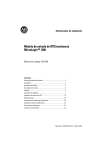
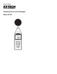
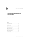
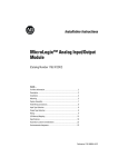
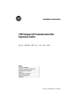
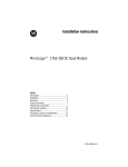
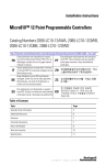
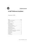
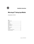
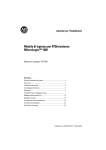
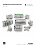
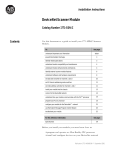
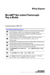
Installation Instructions
MicroLogix 1200 RTD/Resistance Input Module
Catalog Number 1762-IR4
Topic
Page
Module Overview
2
Description
2
Module Installation
3
System Assembly
4
Mounting
4
Field Wiring Connections
7
I/O Memory Mapping
15
Specifications
19
North American Hazardous Location Approval
22
Additional Resources
23
Publication 1762-IN014B-EN-P - July 2013
2
MicroLogix 1200 RTD/Resistance Input Module
Module Overview
The 1762-IR4 module receives and stores digitally converted analog data from RTDs or other
resistance inputs, such as potentiometers. The module supports connections from any
combination of up to 4 RTDs or other resistance inputs. See the input specifications on page 20
for supported RTD and resistance types, their associated temperature ranges, and the analog
input signal ranges that each channel supports. Each of the 4 input channels is individually
configurable for a specific input device and provides open- or short-circuit and over- or
under-range indication.
Description
9
1a
1a
3
7
6
6
2
5
1b
4
8
2
1b
Item Description
Item Description
1a
upper panel mounting tab
5
bus connector cover
1b
lower panel mounting tab
6
flat ribbon cable with bus connector (female)
2
power diagnostic LED
7
terminal block
3
module door with terminal identification
label
8
DIN rail latch
4
bus connector with male pins
9
pull loop
Publication 1762-IN014B-EN-P - July 2013
MicroLogix 1200 RTD/Resistance Input Module
3
Module Installation
1762 I/O is suitable for use in an industrial environment when installed in accordance with these
instructions. Specifically, this equipment is intended for use in clean, dry environments
(Pollution degree 2(1)) and to circuits not exceeding Over Voltage Category II(2) (IEC
60664-1).(3)
Prevent Electrostatic Discharge
ATTENTION
Electrostatic discharge can damage integrated circuits or semiconductors
if you touch bus connector pins. Follow these guidelines when you handle
the module:
• Touch a grounded object to discharge static potential.
• Wear an approved wrist-strap grounding device.
• Do not touch the bus connector or connector pins.
• Do not touch circuit components inside the module.
• If available, use a static-safe work station.
• When not in use, keep the module in its static-shield box.
Remove Power
ATTENTION
Remove power before removing or installing this module. When you
remove or install a module with power applied, an electrical arc may occur.
An electrical arc can cause personal injury or property damage by:
• sending an erroneous signal to your system’s field devices, causing
unintended machine motion
• causing an explosion in a hazardous environment
• causing permanent damage to the module’s circuitry
Electrical arcing causes excessive wear to contacts on both the module and
its mating connector. Worn contacts may create electrical resistance.
(1)
Pollution Degree 2 is an environment where, normally, only non-conductive pollution occurs except that occasionally a
temporary conductivity caused by condensation shall be expected.
(2)
Over Voltage Category II is the load level section of the electrical distribution system. At this level transient voltages are
controlled and do not exceed the impulse voltage capability of the product’s insulation.
(3)
Pollution Degree 2 and Over Voltage Category II are International Electrotechnical Commission (IEC) designations.
Publication 1762-IN014B-EN-P - July 2013
4
MicroLogix 1200 RTD/Resistance Input Module
System Assembly
The expansion I/O module is attached to the controller or another I/O module by means of a
ribbon cable after mounting as shown below.
TIP
WARNING
Use the pull loop on the connector to disconnect modules. Do not pull
on the ribbon cable.
EXPLOSION HAZARD
• In Class I, Division 2 applications, the bus connector must be fully
seated and the bus connector cover must be snapped in place.
• In Class I, Division 2 applications, all modules must be mounted in
direct contact with each other as shown on page 5. If DIN rail
mounting is used, an end stop must be installed ahead of the
controller and after the last 1762 I/O module.
Mounting
ATTENTION
Do not remove protective debris strip until after the module and all other
equipment near the module is mounted and wiring is complete. Once
wiring is complete and the module is free of debris, carefully the remove
protective debris strip. Failure to remove the strip before operating can
cause overheating.
Publication 1762-IN014B-EN-P - July 2013
MicroLogix 1200 RTD/Resistance Input Module
5
Minimum Spacing
Top
Side
1762 I/O
MicroLogix 1200
1762 I/O
Side
1762 I/O
Maintain spacing from enclosure
walls, wireways, adjacent
equipment, etc. Allow 50.8 mm
(2 in.) of space on all sides for
adequate ventilation, as shown:
Bottom
TIP
ATTENTION
The 1762 expansion I/O may be mounted horizontally only.
During panel or DIN rail mounting of all devices, be sure that all debris
(metal chips, wire strands, etc.) is kept from falling into the module.
Debris that falls into the module could cause damage when power is
applied to the module.
DIN Rail Mounting
The module can be mounted using the following DIN rails: 35 x 7.5 mm
(EN 50 022 - 35 x 7.5) or 35 x 15 mm (EN 50 022 - 35 x 15).
Before mounting the module on a DIN rail, close the DIN rail latch. Press the DIN rail
mounting area of the module against the DIN rail. The latch will momentarily open and lock
into place.
Publication 1762-IN014B-EN-P - July 2013
6
MicroLogix 1200 RTD/Resistance Input Module
Use DIN rail end anchors (Allen-Bradley part number 1492-EA35 or 1492-EAH35) for
environments with vibration or shock concerns.
End Anchor
End Anchor
TIP
For environments with extreme vibration and shock concerns, use the
panel mounting method described below, instead of DIN rail
mounting.
Panel Mounting
Use the dimensional template shown below to mount the module. The preferred mounting
method is to use two M4 or #8 panhead screws per module. M3.5 or #6 panhead screws may also
be used, but a washer may be needed to ensure a good ground contact. Mounting screws are
required on every module.
For more than two modules: (number of modules - 1) x 40.4 mm (1.59 in.)
40.4
(1.59)
NOTE:
Hole spacing tolerance: ±0.4 mm (0.016 in.).
Publication 1762-IN014B-EN-P - July 2013
1762 I/O
1762 I/O
40.4
(1.59)
1762 I/O
100 90
(3.94) (3.54)
MicroLogix 1200
14.5
(0.57)
MicroLogix 1200 RTD/Resistance Input Module
7
Field Wiring Connections
Grounding the Module
This product is intended to be mounted to a well-grounded mounting surface such as a metal
panel. Additional grounding connections from the module’s mounting tabs or DIN rail (if used)
are not required unless the mounting surface cannot be grounded. Refer to Industrial
Automation Wiring and Grounding Guidelines, Allen-Bradley publication 1770-4.1, for
additional information.
System Wiring Guidelines
Consider the following when wiring your system:
• Do not use the module’s NC terminals as connection points.
• Use Belden shielded, twisted-pair wire to ensure proper operation and high immunity to
electrical noise. See “RTD Wiring Considerations”.
• To limit noise, locate RTD and resistance device signal wires as far away as possible from
power lines, load lines, and other sources of electrical noise, such as hard-contact
switches, relays, and AC motor drives.
• Locate RTD modules away from other modules which generate a significant amount of
heat.
• Under normal conditions, the drain wire and shield junction should be connected to
earth ground, via a panel or DIN rail mounting screw at the 1762-IR4 module end.
• Keep shield connection to ground as short as possible.
• To ensure optimum accuracy, limit overall cable impedance by keeping your cable as
short as possible. Locate the I/O system as close to your sensors or actuators as your
application will permit. See the table on the following page.
Terminal Block Layout
EXC 2
SENSE 2
NC terminals are not intended for
use as connection points.
Do not connect any wires to the NC
terminals.
RTN 2
NC
NC
NC
NC
EXC 3
SENSE 3
RTN 3
EXC 0
SENSE 0
RTN 0
NC
NC
EXC 1
SENSE 1
RTN 1
Publication 1762-IN014B-EN-P - July 2013
8
MicroLogix 1200 RTD/Resistance Input Module
RTD Wiring Considerations
Since the operating principle of the RTD module is based on the measurement of resistance, take
special care when selecting your input cable. For 2-wire or 3-wire configurations, select a cable
that has a consistent impedance throughout its entire length.
Configuration
Recommended Cable
2-wire
Belden™ 9501 or equivalent
3-wire — less than 30.48 m (100ft.)
Belden™ 9533 or equivalent
3-wire — greater than 30.48 m (100 ft.) or high humidity conditions
Belden™ 83503 or equivalent
IMPORTANT
The RTD module requires three wires to compensate for lead resistance
error. We recommend that you do not use 2-wire RTDs if long cable runs
are required, as it reduces the accuracy of the system. However, if a
two-wire configuration is required, reduce the effect of the lead wire
resistance by using a lower gauge wire for the cable (for example, use
AWG #16 instead of AWG #24). The module’s terminal block accepts
two AWG #14 gauge wires.
When using a 3-wire configuration, the module compensates for resistance error due to lead wire
length. For example, in a 3-wire configuration, the module reads the resistance due to the length
of one of the wires and assumes that the resistance of the other wire is equal. If the resistances of
the individual lead wires are much different, an error may exist. The closer the resistance values
are to each other, the greater the amount of error is eliminated.
IMPORTANT
To ensure temperature or resistance value accuracy, the resistance
difference of the cable lead wires must be equal to or less than 0.01Ω .
To insure that the lead values match as closely as possible:
• Keep lead resistance as small as possible and less than 25Ω .
• Use quality cable that has a small tolerance impedance rating.
• Use a heavy-gauge lead wire which has less resistance per foot.
Publication 1762-IN014B-EN-P - July 2013
MicroLogix 1200 RTD/Resistance Input Module
9
RTD Wiring Configurations
For a 3-wire configuration, the module can compensate for a maximum cable length associated
with an overall cable impedance of 25 ohms.
Three configurations of RTDs can be connected to the 1762-IR4 module:
• 2-wire RTD, which is composed of an RTD EXC (excitation) lead wire and a RTN
(return) lead wire
• 3-wire RTD, which is composed of a Sense and 2 RTD lead wires
(RTD EXC and RTN)
• 4-wire RTD, which is composed of a Sense and 2 RTD lead wires
(RTD EXC and RTN). The second sense wire of a 4-wire RTD is left open.
2-Wire RTD Configuration
Cable Shield (to Ground)
EXC 2
SENSE 2
RTN 2
RTD EXC
RTD EXC
Return
Return
Belden 9501 Shielded Cable
NC
IMPORTANT
Using 2-wire configurations does not permit the module to compensate for
resistance error to do lead wire length. The resulting analog data includes
the effect of this uncompensated lead wire resistance. The module
continues to place the uncompensated analog data in the input data file, but
the open-circuit status bit (OCx) is set in word 4 of the input data file for
any enabled channel using a 2-wire configuration. These status bits may be
used in the control program to indicate that the analog data includes error
due to uncompensated lead wires. See page 16 for a detailed discussion of
the open-circuit status bits.
Publication 1762-IN014B-EN-P - July 2013
10
MicroLogix 1200 RTD/Resistance Input Module
3-Wire RTD Configuration
Cable Shield (to Ground)
RTD EXC
RTD EXC
Sense
Sense
Return
Return
EXC 2
SENSE 2
RTN 2
Belden 83503 or 9533 Shielded Cable
NC
4-Wire RTD Configuration
Cable Shield (to Ground)
EXC 2
SENSE 2
RTN 2
NC
RTD EXC
RTD EXC
Sense
Sense
Return
Return
Belden 83503 or 9533 Shielded Cable
Leave one sensor wire open.
Wiring Resistance Devices (Potentiometers)
Potentiometer wiring requires the same type of cable as that for the RTD described on page 8.
Potentiometers can be connected to the module as a 2-wire or 3-wire connection as shown on
page 11.
Publication 1762-IN014B-EN-P - July 2013
MicroLogix 1200 RTD/Resistance Input Module
11
2-Wire Potentiometer Interconnection
Potentiometer
Cable Shield (to Ground)
RTD EXC
EXC 2
SENSE 2
Return
RTN 2
Belden 9501 Shielded Cable
NC
Cable Shield (to Ground)
Potentiometer
EXC 2
RTD EXC
SENSE 2
RTN 2
NC
TIP
IMPORTANT
Return
Belden 9501 Shielded Cable
The potentiometer wiper arm can be connected to either the EXC or
return terminal, depending on whether you want increasing or decreasing
resistance.
Using 2-wire configurations does not permit the module to compensate for
resistance error to do lead wire length. The resulting analog data includes
the effect of this uncompensated lead wire resistance. The module
continues to place the uncompensated analog data in the input data file, but
the open-circuit status bit (OCx) is set in word 4 of the input data file for
any enabled channel using a 2-wire configuration. These status bits may be
used in the control program to indicate that the analog data includes error
due to uncompensated lead wires. See page 16 for a detailed discussion of
the open-circuit status bits.
Publication 1762-IN014B-EN-P - July 2013
12
MicroLogix 1200 RTD/Resistance Input Module
3-Wire Potentiometer Interconnection
Cable Shield (to Ground)
Run RTD EXC and sense wires from the module to potentiometer
terminal and tie terminal to one point.
Potentiometer
RTD EXC
EXC 2
Sense
SENSE 2
RTN 2
Return
Belden 83503 or 9533 Shielded Cable
NC
Run RTD EXC and sense wires from the module to potentiometer
terminal and tie terminal to one point.
Cable Shield (to Ground)
EXC 2
SENSE 2
RTN 2
RTD EXC
Sense
Return
Belden 83503 or 9533 Shielded Cable
NC
TIP
Potentiometer
The potentiometer wiper arm can be connected to either the EXC or
return terminal depending on whether you want increasing or decreasing
resistance.
Publication 1762-IN014B-EN-P - July 2013
MicroLogix 1200 RTD/Resistance Input Module
13
Labeling the Terminals
A write-on label is provided with the module. Mark the identification of each terminal with
permanent ink, and slide the label back into the door.
Wiring the Finger-Safe Terminal Block
ATTENTION
Be careful when stripping wires. Wire fragments that fall into a module
could cause damage when power is applied. Once wiring is complete,
ensure the module is free of all metal fragments.
When wiring the terminal block, keep the finger-safe cover in place.
1. Route the wire under the terminal pressure plate. You can use the stripped end of the
wire or a spade lug. The terminals will accept a 6.35 mm (0.25 in.) spade lug.
2. Tighten the terminal screw making sure the pressure plate secures the wire.
Recommended torque when tightening terminal screws is 0.904 Nm (8 lb-in.).
3. After wiring is complete, remove the debris shield.
TIP
If you need to remove the finger-safe cover, insert a screw driver into one
of the square wiring holes and gently pry the cover off. If you wire the
terminal block with the finger-safe cover removed, you will not be able
to put it back on the terminal block because the wires will be in the way.
Publication 1762-IN014B-EN-P - July 2013
14
MicroLogix 1200 RTD/Resistance Input Module
Wire Size and Terminal Screw Torque
Each terminal accepts up to two wires with the following restrictions:
Wire Type
Wire Size
Terminal Screw Torque
Solid
Cu-90 °C (194°F)
#14…22 AWG
0.904 Nm (8 lb-in.)
Stranded
Cu-90 °C (194°F)
#16…22 AWG
0.904 Nm (8 lb-in.)
Wiring Input Devices to the 1762-IR4
ATTENTION
Be careful when stripping wires. Wire fragments that fall into a module
could cause damage at power up. Once wiring is complete, ensure the
module is free of all metal fragments.
After the module is properly installed, follow the wiring procedure below, using Belden 83503 or
9533 shielded cable.
cable
Cut foil shield and
drain wire
signal wire
signal wires (2)
signal wire
foil shield
drain wire
cable
Cut foil shield and
drain wire
signal wire (3)
drain wire
Publication 1762-IN014B-EN-P - July 2013
foil shield
signal wires (3)
MicroLogix 1200 RTD/Resistance Input Module
15
To wire your sensor to the module, follow these steps:
1. At each end of the cable, strip some casing to expose the individual wires.
2. Trim the signal wires to 2-inch lengths. Strip about 3/16 inch (5 mm) of insulation away
to expose the end of the wire.
3. At one end of the cable, twist the drain wire and foil shield together, bend them away
from the cable, and apply shrink wrap. Then earth ground at the preferred location based
on the type of sensor you are using.
4. At the other end of the cable, cut the drain wire and foil shield back to the cable and
apply shrink wrap.
5. Connect the signal wires to the module terminal block and input.
6. Repeat steps 1 through 5 for each channel on the module.
I/O Memory Mapping
Addressing
The addressing scheme for 1762 Expansion I/O is shown below.
Slot Number (1)
Word
Data File
File Type = Input
I1:x.0/0
Slot Delimiter
Bit
Bit Delimiter
Word Delimiter
(1)
I/O located on the controller (embedded I/O) is slot 0. I/O added to the controller (expansion I/O) begins with slot 1.
Publication 1762-IN014B-EN-P - July 2013
16
MicroLogix 1200 RTD/Resistance Input Module
Input Data File
For each module, slot x, words 0 through 3 contain the analog values of the inputs. Words 4 and
5 provide sensor/channel status feedback. The input data file for each configuration is shown
below.
Word/
Bit
15
14
13
12
11
10
9
8
7
6
5
0
RTD/Resistance Input Data Channel 0
1
RTD/Resistance Input Data Channel 1
2
RTD/Resistance Input Data Channel 2
3
3
2
1
0
S3
S2
S1
S0
RTD/Resistance Input Data Channel 3
4
5
4
Reserved
U0
O0
U1
OC3 OC2 OC1 OC0
O1
U2
O2
U3
O3
Reserved
Reserved
The bits are defined as follows:
• Sx = General status bits for input channels 0…3. This bit is set (1) when an error (overor under-range, open-circuit or input data not valid condition) exists for that channel, or
there is a general module hardware error. An input data not valid condition is
determined by the user program. See the MicroLogix™ 1200 RTD/Resistance Input
Module User Manual, publication number 1762-UM003, for details.
• OCx = Open-circuit indication for channels 0…3, using either RTD or resistance inputs.
Short-circuit detection for RTD inputs only. Short-circuit detection for resistance
inputs is not indicated because 0 is a valid number.
• Ox = Over-range flag bits for input channels 0…3, using either RTD or resistance inputs.
These bits can be used in the control program for error detection.
• Ux = Under-range flag bits for channels 0…3, using RTD inputs only.
These bits can be used in the control program for error detection. Under-range detection
for direct resistance inputs is not indicated because 0 is a valid number.
Configuration Data File
The configuration of the format for analog inputs and outputs is made at going to run (GTR).
Changes made to the configuration file while in run mode have no effect. Words 0…3 of the
configuration file allow you to change the parameters of each channel independently. Word 0
corresponds to Channel 0, Word 1 to Channel 1, etc. The functional arrangement of the bits is
shown below for a single word/channel.
Publication 1762-IN014B-EN-P - July 2013
MicroLogix 1200 RTD/Resistance Input Module
Make these bit settings
15 14 13 12 11 10 9 8 7 6 5
4
Excitation
Current
Enable
0
Disable
1
Temperature
Units Mode
Open-circuit/
Broken Input
1.0 mA
Input/Sensor Type
3
10 Hz
60 Hz
50 Hz
250Hz
500 Hz
1 kHz
Cyclic Lead
Compensation
Filter Frequency
To Select
0
0.5 mA
1
Upscale
0
0
Downscale
0
1
Last State
1
0
Zero
1
1
°C
0
°F
1
100Ω Pt 385
200Ω Pt 385
500Ω Pt 385
1000Ω Pt 385
100Ω Pt 3916
200Ω Pt 3916
500Ω Pt 3916
1000Ω Pt 3916
10Ω Cu 426
120Ω Ni 618
120Ω Ni 672
604Ω NiFe 518
150Ω
500Ω
1000Ω
3000Ω
0
0
0
0
0
0
0
0
1
1
1
1
1
1
1
1
0
0
0
0
1
1
1
1
0
0
0
0
1
1
1
1
0
0
1
1
0
0
1
1
0
0
1
1
0
0
1
1
2
1
0
0
0
1
1
17
1
1
0
0
1
0
0
0
0
0
1
1
0
1
0
1
0
1
0
1
0
1
0
1
0
1
0
1
0
1
Publication 1762-IN014B-EN-P - July 2013
18
MicroLogix 1200 RTD/Resistance Input Module
Raw/Proportional
Engineering Units
Engr. Units X 10
Scaled-for-PID
Percent Range
Make these bit settings
15 14 13 12 11 10 9 8 7 6 5
0 0 0
0 0 1
1 0 0
0 1 0
0 1 1
Enable
1
Disable
0
Enable
Channel
Data Format
To Select
4
3
2
1
0
Module Configuration Word
Word 4 of the configuration data file contains the Enable/Disable Cyclic Calibration bit, as
shown in the table below.
To Select
Cyclic
Calibration
(1)
Make these bit settings
15 14 13 12 11 10 9 8 7 6 5
Enabled(1)
Disabled
When enabled, an autocalibration cycle is performed on all enabled channels every 5 minutes.
Publication 1762-IN014B-EN-P - July 2013
4
3
2
1
0
0
1
MicroLogix 1200 RTD/Resistance Input Module
19
Specifications
General Specifications
Specification
Value
Dimensions, HxWxD
90 x 40 x 87 mm (3.54 x1.58 x 3.43 in.)
height including mounting tabs is 110 mm (4.33 in.)
Approximate Shipping Weight
(with carton)
260 g (0.57 lbs.)
Storage Temperature
-40…85 °C (-40…185 °F)
Operating Temperature
0…55 °C (+32…131 °F)
Operating Humidity
5…95% non-condensing
Operating Altitude
2000 m (6561 ft)
Vibration
Operating: 10…500 Hz, 5 g, 0.030 in. max. peak-to-peak
Shock
Operating: 30 g
Bus Current Draw (max.)
40 mA @ 5V DC
50 mA @ 24V DC
Heat Dissipation
1.5 Watts
Input Group to System Isolation
30V AC/30V DC rated working voltage(1)
(N.E.C. Class 2 required)
(IEC Class 2 reinforced insulation)
type test: 500V AC or 707V DC for 1 minute
Module Power LED
On: indicates power is applied.
Vendor I.D. Code
1
Product Type Code
10
Product Code
65
Hazardous Environment Class
Class I, Division 2, Hazardous Location, Groups A, B, C, D
ISA/ANSI 12.12.01
(C-UL under CSA C22.2 No. 213)
Radiated and Conducted Emissions
EN50081-2 Class A
ESD Immunity (EN61000-4-2)
4 kV contact, 8 kV air, 4 kV indirect
Radiated Immunity (EN61000-4-3)
10 V/m, 80…1000 MHz, 80% amplitude modulation, +900 MHz
keyed carrier
Fast Transient Burst (EN61000-4-4)
2 kV, 5 kHz
Surge Immunity (EN61000-4-5)
1 kV galvanic gun
Conducted Immunity (EN61000-4-6)
10V, 0.15…80 MHz(2)
(1)
Rated working voltage is the maximum continuous voltage that can be applied at the terminals with respect to earth ground.
(2)
Conducted Immunity frequency range may be 150 kHz to 30 MHz if the Radiated Immunity frequency range is 30 MHz to
1000 MHz.
Publication 1762-IN014B-EN-P - July 2013
20
MicroLogix 1200 RTD/Resistance Input Module
Input Specifications
Specification
1762-IR4
Input Types
100Ω Platinum 385
200Ω Platinum 385
500Ω Platinum 385
1000Ω Platinum 385
100Ω Platinum 3916
200Ω Platinum 3916
500Ω Platinum 3916
1000Ω Platinum 3916
Converter Type
Sigma-Delta
Resolution
Input filter and configuration dependent.
Refer to the MicroLogix 1200 RTD/Resistance Input Module User
Manual, publication number 1762-UM003, for more information.
Common Mode Rejection
110 dB minimum @ 50 Hz with the 10 or 50 Hz filter selected
110 dB minimum @ 60 Hz with the 10 or 60 Hz filter selected
Normal Mode Rejection Ratio
70 dB minimum @ 50 Hz with the 10 or 50 Hz filter selected
70 dB minimum @ 60 Hz with the 10 or 60 Hz filter selected
Non-linearity (in percent full-scale)
±0.05 %
Typical Accuracy
[Autocalibration Enabled] at 25 °C
(77 °F) Ambient with Module
Operating Temperature at 25 °C
(77 °F) (1)
±0.5 °C (°F) for Pt 385
±0.4 °C (°F) for Pt 3916
±0.2 °C (°F) for Ni
±0.3 °C (°F) for NiFe
±0.6 °C (°F) for Cu
(1)
10Ω Copper 426
120Ω Nickel 672
120Ω Nickel 618
604Ω Nickel-Iron 518
0…150Ω
0…500Ω
0…1000Ω
0…3000Ω
±0.15Ω for 150Ω range
±0.5Ω for 500Ω range
±1.0Ω for 1000Ω range
±1.5Ω for 3000Ω range
Accuracy is dependent upon the Analog/Digital converter filter rate selection, excitation current selection, data format, and
input noise.
Specification
1762-IR4
Typical Accuracy
[Autocalibration
Enabled] @ 0…55 °C
(32…131 °F)
±0.9 °C (°F) for Pt 385
±0.8 °C (°F) for Pt 3916
±0.4 °C (°F) for Ni
±0.5 °C (°F) for NiFe
±1.1 °C (°F) for Cu
±0.25Ω for 150 Ω range
±0.8Ω for 500 Ω range
±1.5Ω for 1000 Ω range
±2.5Ω for 3000 Ω range
Accuracy Drift @
0…55 °C (32…131°F)
±0.026 °C/°C (0.026 °F/°F) for Pt 385
±0.023 °C/°C (0.023 °F/°F) for Pt 3916
±0.012 °C/°C (0.012 °F/°F) for Ni
±0.015 °C/°C (0.015 °F/°F) for NiFe
±0.032 °C/°C (0.032 °F/°F) for Cu
±0.007Ω/°C (0.012Ω/°F) for 150Ω range
±0.023Ω/°C (0.041Ω/°F) for 500Ω range
±0.043Ω/°C (0.077Ω/°F) for 1000Ω range
±0.072Ω/°C (0.130Ω/°F) for 3000Ω range
Repeatability(1)
±0.1 °C (±0.18 °F) for Ni and NiFe
±0.2 °C (±0.36 °F) for other RTD inputs
±0.04Ω for 150Ω resistances
±0.2Ω for other resistances
Excitation Current Source 0.5 mA and 1.0 mA selectable per channel
Open-Circuit Detection
Time(2)
6…1212 ms
Channel Update Time
Input filter and configuration dependent. Refer to the MicroLogix 1200
RTD/Resistance Input Module User Manual, publication number 1762-UM003, for
more information.
Publication 1762-IN014B-EN-P - July 2013
MicroLogix 1200 RTD/Resistance Input Module
21
Specification
1762-IR4
Input Channel
Configuration
Via configuration software screen or the user program (by writing a unique bit
pattern into the module’s configuration file). Refer to your controller’s user manual to
determine if user program configuration is supported.
Calibration
The module performs autocalibration on channel enable and on a configuration
change between channels. You can also program the module to calibrate every five
minutes.
Module OK LED
On: module has power, has passed internal diagnostics, and is communicating over
the bus.
Off: Any of the above is not true.
Channel Diagnostics
Over- or under-range or broken input by bit reporting
Maximum Overload at
Input Terminals
±35V DC continuous
Cable Impedance Max.
25Ω (Operating with >25Ω will reduce accuracy.)
Input Impedance
>10 MΩ
Power Supply Distance
Rating
6 (The module may not be more than 6 modules away from the controller.)
Channel to Channel
Isolation
±10V DC
(1)
Repeatability is the ability of the module to register the same reading in successive measurements for the same input
signal.
(2)
Open-circuit detection time is equal to channel update time for EXC and RTN leads only, Open-circuit detection on SENSE
input is performed during Cyclic Lead Calibration (every 5 minutes) and only on those channels where cyclic lead calibration
is enabled.
Certifications
Certification (when
Value
product is marked)(1)
c-UL-us
UL Listed Industrial Control Equipment, certified for US and Canada.
UL Listed for Class I, Division 2 Group A,B,C,D Hazardous Locations, certified for
U.S. and Canada. See UL File E334470.
CE
European Union 2004/108/EC EMC Directive, compliant with:
EN 61326-1; Meas./Control/Lab., Industrial Requirements
EN 61000-6-2; Industrial Immunity
EN 61000-6-4; Industrial Emissions
EN 61131-2; Programmable Controllers (Clause 8, Zone A & B)
C-Tick
Australian Radiocommunications Act, compliant with:
AS/NZS CISPR 11; Industrial Emissions
KC
Korean Registration of Broadcasting and Communications Equipment,
compliant with:
Article 58-2 of Radio Waves Act, Clause 3
(1)
See the Product Certification link at http://www.rockwellautomation.com/products/certification for Declaration of
Conformity, Certificates, and other certification details.
Publication 1762-IN014B-EN-P - July 2013
22
MicroLogix 1200 RTD/Resistance Input Module
North American Hazardous Location Approval
The following modules are North American Hazardous Location approved: 1762-IR4
The following information applies when
operating this equipment in hazardous
locations:
Informations sur l’utilisation de cet
équipement en environnements dangereux:
Products marked "CL I, DIV 2, GP A, B, C, D" are
suitable for use in Class I Division 2 Groups A, B, C,
D, Hazardous Locations and nonhazardous
locations only. Each product is supplied with
markings on the rating nameplate indicating the
hazardous location temperature code. When
combining products within a system, the most
adverse temperature code (lowest "T" number) may
be used to help determine the overall temperature
code of the system. Combinations of equipment in
your system are subject to investigation by the
local Authority Having Jurisdiction at the time of
installation.
Les produits marqués "CL I, DIV 2, GP A, B, C, D" ne
conviennent qu'à une utilisation en environnements de
Classe I Division 2 Groupes A, B, C, D dangereux et non
dangereux. Chaque produit est livré avec des
marquages sur sa plaque d'identification qui indiquent
le code de température pour les environnements
dangereux. Lorsque plusieurs produits sont combinés
dans un système, le code de température le plus
défavorable (code de température le plus faible) peut
être utilisé pour déterminer le code de température
global du système. Les combinaisons d'équipements
dans le système sont sujettes à inspection par les
autorités locales qualifiées au moment de l'installation.
WARNING
EXPLOSION HAZARD
•
Do not disconnect equipment
unless power has been removed
or the area is known to be
nonhazardous.
•
AVERTISSEMENT
RISQUE D’EXPLOSION
•
Couper le courant ou s’assurer que
l’environnement est classé non
dangereux avant de débrancher
l'équipement.
Do not disconnect connections to
this equipment unless power has
been removed or the area is
known to be nonhazardous.
Secure any external connections
that mate to this equipment by
using screws, sliding latches,
threaded connectors, or other
means provided with this product.
•
Couper le courant ou s'assurer que
l'environnement est classé non
dangereux avant de débrancher les
connecteurs. Fixer tous les
connecteurs externes reliés à cet
équipement à l'aide de vis, loquets
coulissants, connecteurs filetés ou
autres moyens fournis avec ce
produit.
•
Substitution of components may
impair suitability for Class I,
Division 2.
•
•
If this product contains batteries,
they must only be changed in an
area known to be nonhazardous.
La substitution de composants peut
rendre cet équipement inadapté à une
utilisation en environnement de
Classe I, Division 2.
•
S’assurer que l’environnement est
classé non dangereux avant de
changer les piles.
•
All wiring must comply with
N.E.C. article 501-4(b).
•
The interior of the enclosure must
be accessible only by the use of a
tool.
•
For applicable equipment (relay
modules, etc.), exposure to some
chemicals may degrade the
sealing properties of materials
used in the following devices:
Relays, Epoxy. It is recommended
that the User periodically inspect
these devices for any degradation
of properties and replace the
module if degradation is found.
Publication 1762-IN014B-EN-P - July 2013
MicroLogix 1200 RTD/Resistance Input Module
23
Additional Resources
Publication
Description
MicroLogix 1200 Programmable Controllers User
Manual, publication 1762-UM001.
Information on installing, wiring, and operating a
MicroLogix 1200 Programmable Controller
MicroLogix 1200 Programmable Controllers Installation
Instructions, publication 1762-IN006.
Installation guide for the MicroLogix 1200
Programmable Controller.
MicroLogix 1200 Memory Module and/or Real Time
Clock Installation Instructions, publication 1762-IN001.
Installation guide for the MicroLogix 1200 Memory
Module and Real Time clock.
1762-IA8 120V AC Input Module Installation Instructions, Installation guide for the 1762-IA8 Discrete Input
publication 1762-IN002.
Module
1762-OW8 Relay Output Module Installation
Instructions, publication 1762-IN003.
Installation guide for the 1762-OW8 Discrete Output
Module
1762-IQ8 DC Input Module Installation Instructions,
publication 1762-IN004.
Installation guide for the 1762-IQ8 Discrete Input
Module
Industrial Automation Wiring and Grounding Guidelines, More information on proper wiring and grounding
publication 1770-4.1.
techniques.
If you would like a manual, you can:
• download a free electronic version from the internet:
http://literature.rockwellautomation.com.
• purchase a printed manual by contacting your local Allen-Bradley distributor or
Rockwell Automation representative
Publication 1762-IN014B-EN-P - July 2013
Rockwell Automation Support
Rockwell Automation provides technical information on the Web to assist you in using its products. At
http://www.rockwellautomation.com/support/, you can find technical manuals, a knowledge base of FAQs,
technical and application notes, sample code and links to software service packs, and a MySupport feature that
you can customize to make the best use of these tools.
For an additional level of technical phone support for installation, configuration and troubleshooting, we offer
TechConnect support programs. For more information, contact your local distributor or Rockwell Automation
representative, or visit http://www.rockwellautomation.com/support/.
Installation Assistance
If you experience a problem within the first 24 hours of installation, please review the information that's
contained in this manual. You can also contact a special Customer Support number for initial help in getting your
product up and running.
United States or 1.440.646.3434
Canada
Outside United
States or
Canada
Use the Worldwide Locator at
http://www.rockwellautomation.com/support/americas/phone_en.html, or
contact your local Rockwell Automation representative.
New Product Satisfaction Return
Rockwell Automation tests all of its products to ensure that they are fully operational when shipped from the
manufacturing facility. However, if your product is not functioning and needs to be returned, follow these
procedures.
United States
Contact your distributor. You must provide a Customer Support case
number (call the phone number above to obtain one) to your distributor
to complete the return process.
Outside United States
Please contact your local Rockwell Automation representative for the
return procedure.
Documentation Feedback
Your comments will help us serve your documentation needs better. If you have any suggestions on how to
improve this document, complete this form, publication RA-DU002, available at
http://www.rockwellautomation.com/literature/.
Allen-Bradley, Rockwell Automation, MicroLogix, and TechConnect are trademarks of Rockwell Automation, Inc.
Trademarks not belonging to Rockwell Automation are property of their respective companies.
Publication 1762-IN014B-EN-P - July 2013
Supersedes Publication 1762-IN014B-EN-P - October 2002
Copyright © 2013 Rockwell Automation, Inc. All rights reserved.