1
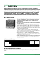
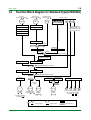
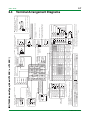
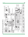
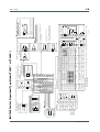
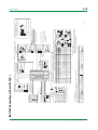
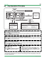
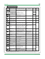
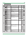
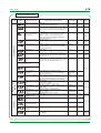
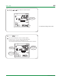
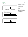
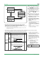
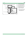
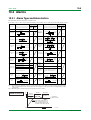
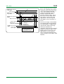
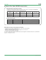
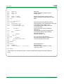
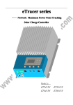
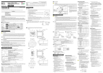
3-5
<Toc> <Ind>
3.4
PARAMETERS
3.4.1
Parameter Setting Flow
Power ON
Operating
Display
Menu
Press
SET/ENT
SET/ENT
No
Display ?
IN=OFF
All operating parameters are displayed in the order
of this flow chart, Note that some parameters are
displayed only under special condition.
Yes
Determine PV
input type first
Menu
key for 3sec or more
Operating Parameter Setting Display
key
Alarm-2
setpoint
To switch the parameter display, press the
SET/ENT
Displayed only when
password registration
key.
Password input
(No password is required
when PWD = 0.)
Alarm-3
setpoint
Alarm-4
setpoint
Remote/local
switching
SET/ENT
Displayed only with UT450-1 or -3
Displayed when setup
parameter “DIS = 0”
Auto-tuning
Displayed in automatic
operation
See the next page
Pressing the
key when
PID = 1Gr causes PID
for 1.SP to appear.
SUPER function
SET/ENT
Target setpoint
number selection
key
B
Displayed only for controllers
with remote input
Run/stop
switching
Pressing the
key when
PID = 8Gr causes PID
for 8.SP to appear.
SET/ENT
The setpoints (5.SP to 8.SP) are not displayed
in the initial setting
To use 5.SP to 8.SP,
set setup parameter “GRP = 5 to 8”.
Proportional band /
heating-side
proportional band
PID parameter
display number
FL is displayed if you
press the
key
when PID = MENU.
SET/ENT
Integral time / heating-side
integral time
PV input filter
Derivative time /
heating-side
derivative time
PV input bias
Output high limit /
heating-side output
high limit
Setpoint
ramp-up rate
Not displayed for
ON/OFF control
Output low limit /
cooling-side output
high limit
Setpoint
ramp-down rate
Manual reset
Ratio setting
Remote
input bias
key
SET/ENT
Alarm-1
setpoint
Displayed only for
controllers with
remote input
Remote
input filter
ON/OFF control
hysteresis / heating-side
ON/OFF control hysteresis
Displayed for ON/OFF
control
Direct/reverse
action switching
Cooling-side
proportional band
ON/OFF rate
detection band
Cooling-side integral time
ON/OFF rate
high limit
Cooling-side derivative time
ON/OFF rate
low limit
Cooling-side
ON/OFF control hysteresis
Target
setpoint-1
Dead band
Target
setpoint-2
Preset output / heating-side
preset output
Target
setpoint-3
Cooling-side preset output
Displayed for
heating/cooling control
Displayed for heating/cooling
control or position proportional
PID control
Displayed for heating/cooling
control
Target
setpoint-4
Target
setpoint-5
Target
setpoint-6
Not displayed in the initial
setting
Target
setpoint-7
To use 5.SP to 8.SP, set setup
parameter “GRP = 5 to 8”
Target
setpoint-8
F3-04.EPS
TI 05D01C12-01E
1st Edition : Mar. 30, 2001-00