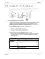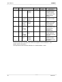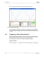
1
JX3-THI2-TC
JetWeb
Peripheral Module
User Manual
Article no.: 60872697
Revision: 1.01.2
March 2008 / Printed in Germany
Introduction
JetWeb
Revision 1.01.2
Jetter AG reserve the right to make alterations to their products in the interest of technical
progress. These alterations need not be documented in every single case.
This manual and the information contained herein have been compiled with due
diligence. However, Jetter AG assume no liability for printing or other errors or damages
arising from such errors.
The brand names and product names used in this document are trademarks or registered
trademarks of the respective title owner.
2
Jetter AG
JX3-THI2-TC
Introduction
How to Contact us:
Jetter AG
Gräterstrasse 2
D-71642 Ludwigsburg
Germany
Phone - Switchboard:
Phone - Sales:
Phone - Technical Hotline:
+49 7141 2550-0
+49 7141 2550-433
+49 7141 2550-444
Fax - Sales:
E-mail - Sales:
E-mail - Technical Hotline:
+49 7141 2550-484
[email protected]
[email protected]
This User Manual is an Integral Part of
the JX3-THI2-TC Module:
Type:
Serial #:
Year of construction:
Order #:
To be entered by the customer:
Inventory #:
Place of operation:
© Copyright 2007, 2008 by Jetter AG. All rights reserved.
Jetter AG
3
Introduction
JetWeb
Significance of this User Manual
This manual is an integral part of the JX3-THI2-TC module, and
•
•
must be kept in a way that it is always at hand until the JX3-THI2-TC module will be
disposed of.
If the JX3-THI2-TC is sold, alienated or loaned, this manual must be handed over.
In any case you encounter difficulties to clearly understand this user manual, please
contact the manufacturer.
We would appreciate any suggestions and contributions on your part and would ask you
to contact us. This will help us to produce manuals that are more user-friendly and to
address your wishes and requirements.
This manual contains important information on how to transport, erect, install, operate,
maintain and repair the JX3-THI2-TC module.
Therefore, the persons carrying out these jobs must carefully read, understand and
observe this manual, and especially the safety instructions.
Missing or inadequate knowledge of the manual results in the loss of any claim of liability
on part of Jetter AG. Therefore, the operating company is recommended to have the
instruction of the persons concerned confirmed in writing.
History
4
Revision
Comment
1.01.1
Original issue
1.01.2
Changes, see Recent Revisions (on page 67)
Jetter AG
JX3-THI2-TC
Introduction
Description of Symbols
This sign is to indicate a possible impending danger of serious physical damage or
death.
Warning
This sign is to indicate a possible impending danger of light physical damage. This sign
is also to warn you of material damage.
Caution
This sign indicates hazard of life due to electric shock caused by a high operating
voltage.
Warning
This sign is to indicate hazard of serious physical damage or death due to accidentally
touching dangerous parts of the device.
Warning
You have to wear goggles. Failure to comply may lead to bodily injuries.
Warning
This sign is to warn you of material damage due to applying hard blows or shocks to the
motor flange and shaft.
This sign is to indicate a possible impending situation which might bring damage to the
product or to its surroundings.
It also identifies requirements necessary to ensure faultless operation.
Important
Jetter AG
5
Introduction
JetWeb
You will be informed of various possible applications and will receive further useful
suggestions.
It also gives you words of advice on how to efficiently use hardware and software in
order to avoid unnecessary efforts.
Note
·/-
Enumerations are marked by full stops, strokes or scores.
Operating instructions are marked by this arrow.
Automatically running processes or results to be achieved are marked by this arrow.
Pictorial representation of PC and HMI keys.
Reference to a program or file.
This symbol informs you of additional references (data sheets, literature, etc.)
associated with the given subject, product, etc. It also helps you to find your way around
this manual.
6
Jetter AG
JX3-THI2-TC
Table of Contents
Table of Contents
1
Safety Instructions
11
1.1 Generally Valid Safety Instructions .......................................................... 11
1.1.1 Intended Conditions of Use of the JX3-THI2-TC ............................. 11
1.1.2 Usage other than intended .............................................................. 11
1.1.3 Who may operate the device?......................................................... 12
1.1.4 Modifications and Alterations to the Module.................................... 12
1.1.5 Repair and Maintenance ................................................................. 12
1.1.6 Decommissioning and Disposing of ................................................ 12
1.2 Ensure Your Own Safety ......................................................................... 13
1.2.1 Malfunctions .................................................................................... 13
1.2.2 Information Signs and Labels.......................................................... 13
1.3 Instructions on EMI .................................................................................. 14
2
Introduction
2.1
2.2
2.3
2.4
3
4
Description of the JX3-THI2-TC Module .................................................. 15
JX3-THI2-TC - Minimum Requirements................................................... 16
JX3-THI2-TC - Scope of Delivery ............................................................ 16
List of Documentation .............................................................................. 17
Description of Connections
3.1
3.2
3.3
3.4
15
19
JX3-THI2-TC - Functional Data of Temperature Inputs ........................... 19
JX3-THI2-TC - Assignment of Terminals X41 and X42 ........................... 20
Connecting Thermocouples ..................................................................... 21
Improving the Noise Immunity ................................................................. 22
Numbering of Registers and I/Os
23
4.1 Register Addressing ................................................................................ 23
4.1.1 Register Array for JX3 Modules ...................................................... 23
4.1.2 Direct Access to JX3 Module Registers .......................................... 26
4.1.3 Indirect Access to JX3 Module Registers ........................................ 27
5
Commissioning the JX3-THI2-TC Module
31
5.1 Approach to Commissioning the Module ................................................. 31
5.1.1 Fast Commissioning of the JX3-THI2-TC Module ........................... 31
6
Digitizing the Analog Values
6.1
6.2
6.3
6.4
Jetter AG
33
Registers with Digitized Analog Value ..................................................... 33
Displaying the Temperature..................................................................... 33
Accuracy as a Function of Noise ............................................................. 34
Variation at 10-fold Averaging ................................................................. 34
7
Table of Contents
7
Status and Instructions
JetWeb
35
7.1 JX3-THI2-TC: Allowed Thermocouple Types .......................................... 39
8
Additional Functions
8.1
8.2
8.3
8.4
8.5
8.6
9
41
Additional Functions - Overview .............................................................. 41
A/D Conversion........................................................................................ 44
Averaging ................................................................................................ 44
Monitoring of Limits.................................................................................. 45
Slave Pointer ........................................................................................... 46
Transfer to the Controller......................................................................... 46
Oscilloscope
47
9.1 Operating Principle .................................................................................. 47
9.1.1 Oscilloscope Mode - Technical Data ............................................... 47
9.2 Recordings via Oscilloscope.................................................................... 47
9.3 Triggering a Recording Session............................................................... 48
9.4 Module Registers - Overview................................................................... 49
9.5 Recordings via Application Program........................................................ 52
10 Forcing Analog Inputs
55
10.1 JX3-THI2 - Functional Principle of Forcing .............................................. 55
10.2 Forcing - Module Register ....................................................................... 56
11 Diagnostics and Administration
11.1
11.2
11.3
11.4
57
JX3-THI2-TC: Behavior in case of errors:................................................ 57
Diagnostic Indicators (LEDs) ................................................................... 57
Diagnostics via JX3 Module Registers..................................................... 58
Electronic Data Sheet (EDS) ................................................................... 62
12 Recent Revisions
67
13 Module Registers - Overview
69
13.1 Overview - JX3-THI2-TC Module Registers............................................. 69
13.2 Table - JX3-THI2-TC Module Registers................................................... 70
14 Design
73
14.1 Physical Dimensions................................................................................ 73
14.2 JX3-THI2-TC Terminals........................................................................... 74
15 Operating Conditions
8
75
Jetter AG
JX3-THI2-TC
15.1
15.2
15.3
15.4
Table of Contents
Environment and Mechanics ................................................................... 75
Enclosure................................................................................................. 76
DC Power Supply Inputs and Outputs ..................................................... 77
Shielded Data and I/O Lines.................................................................... 78
16 Technical Data
79
17 General Information
81
18 Glossary – Peripheral Modules
85
19 List of Illustrations
87
20 Index
89
Jetter AG
9
Table of Contents
10
JetWeb
Jetter AG
JX3-THI2-TC
JetWeb
1
Safety Instructions
1.1
Generally Valid Safety Instructions
This device complies with the valid safety regulations and standards. Special emphasis
was given to the safety of the users.
Of course, the user should adhere to the following regulations:
•
•
•
1.1.1
relevant accident prevention regulations;
accepted safety rules;
EC guidelines and other country-specific regulations.
Intended Conditions of Use of the JX3-THI2-TC
The intended conditions of use include operation in accordance with the user manual.
The JX3-THI2-TC module is a JX3 expansion module equipped with two analog inputs for
connecting analog temperature sensors. It can be connected to the JX3 system bus. The
JX3 system bus starts at the JX3-BN-xxx module. Via JX3-BN-CAN module, the JX3THI2-TC module can be connected to all controllers of the JetControl series. The JX3BN-XXX or JX3-PS1 module supplies the JX3-THI2-TC module with voltage. This
operating voltage is classified as SELV (Safety Extra Low Voltage). The JX3-THI2-TC
module is therefore not subject to the EU Low Voltage Directive.
The JX3-THI2-TC module may only be operated within the limits of the stated
specifications.
The device is used to control machinery, such as conveyors, production machines, and
handling machines.
1.1.2
Usage other than intended
This device must not be used in technical systems which to a high degree have to be failsafe, e.g. ropeways and aeroplanes.
If the device is to be run under ambient conditions which differ from the conditions
mentioned in chapter Operating Conditions (page 75), the manufacturer is to be
contacted beforehand.
Jetter AG
11
JX3-THI2-TC
1.1.3
JetWeb
Who may operate the device?
Only instructed, trained and authorized persons are permitted to operate this device.
Transport:
Installation:
Commissioning:
1.1.4
Only by personnel with knowledge in handling
electrostatically sensitive components.
Only by specialists with training in electrical
engineering.
Only by specialists with profound knowledge of, and
experience with, electrical engineering / drive
technology.
Modifications and Alterations to the Module
For safety reasons, no modifications and changes to the device and its functions are
permitted.
Any modifications to the device not expressly authorized by the manufacturer will result in
a loss of any liability claims to Jetter AG.
The original parts are specifically designed for the device. Parts and equipment
from other manufacturers are not tested on our part, and are, therefore, not
released by us.
The installation of such parts may impair the safety and the proper functioning of the
device.
Any liability on the part of Jetter AG for any damages resulting from the use of non
original parts and equipment is excluded.
1.1.5
Repair and Maintenance
This device must not be repaired by the operators themselves. The device does not
contain any parts that could be repaired by the operator.
The device must be sent to Jetter AG for repair.
1.1.6
Decommissioning and Disposing of
The environmental regulations of the respective country must be complied with when
decommissioning and disposing of devices on the operating company's premises.
12
Jetter AG
JX3-THI2-TC
1.2
JetWeb
Ensure Your Own Safety
Disconnect the JX3-THI2-TC module from the mains to carry out maintenance
work. By doing so, you will prevent accidents resulting from electric voltage and
moving parts.
Warning
Safety and protective devices, e.g. the barrier and cover of the terminal box must
never be shunted or by-passed.
Dismantled protective equipment, such as guards, must be reattached prior to
commissioning and checked for proper functioning.
Prior to commissioning, the machine manufacturer shall conduct a hazard analysis
for the machine and take appropriate measures to prevent personal injury and
damage to property resulting from accidental movements.
1.2.1
Malfunctions
In case of failures or damages, disconnect the device from the mains
immediately.
Malfunctions or other damages are to be reported to a responsible person at
once.
The device must be protected from improper or inadvertent use.
1.2.2
Information Signs and Labels
Markings, information signs, and labels always have to be observed and kept
readable.
Damaged or unreadable information signs and labels have to be replaced.
Jetter AG
13
JX3-THI2-TC
1.3
JetWeb
Instructions on EMI
The noise immunity of a system depends on the weakest component of the system. For
this reason, correct wiring and shielding of cables is of paramount importance.
Important!
Measures for increasing EMI in electric plants:
The JX3-THI2-TC module has to be attached to a DIN rail acc. to EN 50022-35 x
7.5.
If correct measurements are required, the sensor cables connected to inputs
X41 and X42 of the JX3-THI2-TC module have to be looped through a ferrite
core at least once or twice. This way, external interferences can be minimized.
This reduction of interferences can be achieved by using a round cable snap
ferrite (e.g. by Würth Elektronik, part # 74271222). Tests with an RF injection
(10 V/m) resulted in a higher susceptibility to interference. The measuring
accuracy decreased from 0.5°C to 1.5°C in the range of up to 450°C.
Follow the instructions given in Application Note 016 "EMC-Compatible
Installation of the Electric Cabinet" published by Jetter AG.
The following instructions are excerpts from Application Note 016:
On principle, physical separation should be maintained between signal and
voltage lines. We recommend spacings greater than 20 cm. Cables and lines
should cross each other at an angle of 90°.
Shielded cables are to be used for the following lines:
Analog lines, data lines, motor cables coming from inverter drives (servo output
stage, frequency converter), lines between components and interference
suppressor filter, if the suppressor filter has not been placed at the component
directly.
Shield cables at both ends.
Unshielded wire ends of shielded cables should be as short as possible.
The entire shield must be drawn behind the isolation, and then be clamped
under an earthed strain relief with the greatest possible surface area.
14
Jetter AG
JX3-THI2-TC
JetWeb
2
Introduction
2.1
Description of the JX3-THI2-TC Module
The JX3-THI2-TC module is a JX3 expansion module for connecting thermocouples. This
module is equipped with 2 inputs. Via JX3-BN-CAN module, the JX3-THI2-TC module
can be connected to all controllers of the JetControl series.
Description of the JX3-THI2-TC Module
Jetter AG
Article #
10000611
Module Code
312
LED Display
Terminal X41
Supply Voltage
Communication
Hardware error
1 input for connecting thermocouples
Terminal X42
1 input for connecting thermocouples
Additional functions
•
•
•
•
•
•
•
Averaging
Monitoring and evaluation of limits
Operating system update by means of JetSym
Slave pointer
Oscilloscope function
Potentiometer mode
Forcing
15
JX3-THI2-TC
2.2
JetWeb
JX3-THI2-TC - Minimum Requirements
The functions described in this document make the following minimum requirements to
modules, controllers and software.
Minimum Requirements
Module / Controller / Software
JX3-THI2-TC
V 1.01.0.01
JX3-BN-CAN
V 1.04
JC-24x
V 3.23
Oscilloscope Function: V 3.24
V 2.18
Oscilloscope Function: V 2.19
V 3.50
JX6-SB / JX6-SB-I
JC-64x
JetSym
V 3.00
Oscilloscope Function: V 4.00
V 1.12
Oscilloscope Function: V 1.13
JM-D203-JC-24x
2.3
Starting from software release
JX3-THI2-TC - Scope of Delivery
JX3-THI2-TC - Scope of Delivery
Article #
16
Quantity
Description
10000611
1
JX3-THI2-TC
60869252
2
60870411
10
60871941
1
BU_10_BLZF_SW_RM3.5
10-pin male connector, spring cage technology,
contact spacing 3.5 mm
DIV_DEK_5/5_MC-10_NEUT._WS
Terminal labels
Installation instruction
60870410
1
DIV_BL_SL_3.5_KO_OR
Keying pins
Jetter AG
JX3-THI2-TC
2.4
JetWeb
List of Documentation
Document Survey of the JX3-I/O System
JX3-I/O System - User Information
JX3-THI2-TC - Installation Instructions
Jetter AG
17
JX3-THI2-TC
18
JetWeb
Jetter AG
JX3-THI2-TC
JetWeb
3
Description of Connections
3.1
JX3-THI2-TC - Functional Data of Temperature
Inputs
Functional Data
Input quantity:
Two independent channels for thermocouples
Conversion time for measured
temperature
approx. 90 to 150 ms in "slow mode"
approx. 8 to 15 ms in "fast mode"
The conversion time depends on the
measured temperature.
0,01°C
Resolution
Accuracy
Filtering
Jetter AG
See chapter “Accuracy/Noise”.
Cold-junction typically < 4 °C.
10-fold averaging, ambient temperature 25°C,
accuracy to DIN IEC 60584, class A
Software filtering, 2- to 64-fold averaging,
moving average
19
JX3-THI2-TC
3.2
JetWeb
JX3-THI2-TC - Assignment of Terminals X41
and X42
Assignment of Terminal X41
View
Analog input # 1
Pin
Signal
Comment
X41.I1+
X41.U1+
I1+
U1+
X41.U1X41.I1-
U1I1-
X41.0V
X41.BR1
0V
NC
Jumper to 0V
Terminal for the positive
side of thermocouple 1
Jumper to 0V
Terminal for the negative
side of thermocouple 1
Ground
not connected
X41.BR2
X41.0V
X41.SHLD
X41.SHLD
NC
0V
SHLD
SHLD
not connected
Ground
Shielding terminal
Shielding terminal
Assignment of Terminal X42
View
Analog input # 3
Pin
Signal
Comment
X42.I2+
X42.U2+
I2+
U2+
X42.U2X42.I2-
U2I2-
X42.0V
0V
Jumper to 0V
Terminal for the positive
side of thermocouple 2
Jumper to 0V
Terminal for the negative
side of thermocouple 2
Ground
X42.BR3
X42.BR4
NC
NC
not connected
not connected
X42.0V
X42.SHLD
X42.SHLD
0V
SHLD
SHLD
Ground
Shielding terminal
Shielding terminal
This configuration applies to Rev00. Rev01 will no longer require additional
jumpers.
Please use only the provided connectors by Weidmüller (order # 60869252), or identical
connectors.
If BL-IO-3.5 LED is used, incorrect measurements will result as the electronic parts
integrated into the connector influence the measurements.
20
Jetter AG
JX3-THI2-TC
3.3
JetWeb
Connecting Thermocouples
Between I1+ and U1-, as well as between U1- and 0V for the first channel, or I2+ and
U2-, as well as between U2- and 0V for the second channel two jumpers have to be
plugged in.
These jumpers must designed in a way to ensure that the resistance between the
terminals is significantly less than 0.1 Ω.
This configuration applies to Rev00.
Figure 1: Connecting a Thermocouple
Jetter AG
21
JX3-THI2-TC
3.4
JetWeb
Improving the Noise Immunity
For improving the noise immunity, please give heed to the following rules:
•
•
•
•
For the connection of analog sensors, use a shielded connector.
Connect the shielding to terminal X41, respectively X42 directly.
Use a shielding terminal (1) for additionally earthing the shield of the wire.
Use a round cable snap ferrite (e.g. 74271222 by Würth Elektronik).
Figure 2: Additional earthing of a shield by means of a shielding terminal
22
Jetter AG
JX3-THI2-TC
JetWeb
4
Numbering of Registers and I/Os
4.1
Register Addressing
4.1.1
Register Array for JX3 Modules
Each JX3 module is equipped with over 10,000 module registers. The module registers,
on the other hand, have been assigned to the controller registers. By means of registers,
process, configuration and diagnose data can be read by module JX3-THI2-TC,
respectively written to the module.
Registers can be accessed directly in the application program of the controller, in a setup
pane of JetSym, or via the user interface directly.
Register Number
3
0
0
z
Module Register Number
The meaning depends on the module
Register prefix
The meaning depends on the controller
The register number results from a register prefix and a module register number. The
register prefix depends on the position of the JX3-THI2-TC module in the Jetter system
bus, and on the controller that is applied.
At determining the register prefixes, the following parameters have to be considered:
•
•
•
Jetter AG
Controller (JC-24x, JC-64x, JC-800, JM-D203-JC-24x)
Submodule position (at JX6-SB, JX6-SB-I)
I/O module number in the Jetter system bus
23
JX3-THI2-TC
JetWeb
JX3-I/O-modules connected to JC-24x and JM-D203-JC-24x
3
x
x
z
Module register number: 0...9
I/O module number on the Jetter
system bus - 2: 0...61
JX3-I/O module array: 3
JX3-I/O modules with JX6-SB(-I) and JC-647 modules
3
m
0
3
x
x
z
Module register number: 0...9
I/O module number on the Jetter system
bus - 2: 0...61
I/O module range: 03
Submodule position: 1...3
Array: 3
JX3-I/O modules with JX6-SB(-I) and JC-800 modules
4
C
M
0
3
x
x
z
Module register number: 0...9
I/O module number on the Jetter system
bus - 2: 0...61
I/O module range: 03
System bus module: 1...2
Module board number: 1...3
Array: 4
24
Jetter AG
JX3-THI2-TC
JetWeb
Example: Register and I/O Addressing of a JX3 Module on the Jetter
System Bus
Six modules, JX3-BN-CAN (33, 34), JX3-DI16 (2, 4) and JX3-DIO16 (3, 5), have been
connected to a JC-24x (1) controller. The register and I/O numbers listed in the table
below result from the module position on the Jetter system bus.
•
•
•
On the Jetter system bus, no I/O numbers have been assigned to the JX3-BN-CAN.
The first JX3-BN-CAN connected to the JetControl is assigned the I/O module
number 33.
The first JX3 module is assigned I/O module number 2.
Register and I/O Numbers
Jetter AG
IO Module Number
Module
Register Number
IO Numbers
1
JC-24X
101 ... 116
33
JX3-BN-CAN
0 ... 1999
20000 ... 49999
3310 ... 3319
02
JX3-DI16
3000 ... 3009
201 ... 216
03
JX3-DIO16
3010 ... 3019
301 ... 316
34
JX3-BN-CAN
3320 ... 3329
04
JX3-DI16
3020 ... 3029
401 ... 416
05
JX3-DIO16
3030 ... 3039
501 ... 516
-
25
JX3-THI2-TC
4.1.2
JetWeb
Direct Access to JX3 Module Registers
Each JX3 module is equipped with over 10,000 module registers. Eight of these are
directly accessible via Jetter system bus.
Figure 3: Direct register access to JX3 modules
Above, direct access to the JX3 module registers (2) has been illustrated. On the Jetter
system bus of a JC-24x controller, the JX3 modules can be accessed via register
numbers 3xxz (1). Access to JX3 module registers 0 through 6, as well as 9 is carried out
directly via register 3xxz.
Register Numbering Dependent on the Controller
•
•
•
For JC-24x controllers: Register number 3xxz
For JC-647 controllers: Register number 3m03xxz
For JC-800 controllers: Register number 4CM03xxz
Example: Directly Checking the Communication with the JX3
Modules
In a JX3-BN-CAN module, communication with the connected JX3 modules is to be
checked. For this, bit 15 in register 0 the status of the JX3-BN-CAN must be queried.
VAR
nm_State : INT at %vl 3310;
END_VAR;
//
Status register JX3-BN-CAN
//
Bit number
//
Communication active
//
...
CONST
c_ComActive = 15;
END_CONST;
TASK 0
WHEN
BIT_SET (nm_State, c_ComActive)
CONTINUE;
END_TASK;
26
Jetter AG
JX3-THI2-TC
4.1.3
JetWeb
Indirect Access to JX3 Module Registers
Each JX3 module is equipped with over 10,000 module registers. One index and one
data register make access to all 10,000 module registers possible.
Figure 4: Indirect register access to JX3 modules
Above, indirect access to the JX3 module registers (2) has been illustrated. On the Jetter
system bus, the JX3 modules can be accessed via register numbers 3xxz (1). With
indirect access, the number of the JX3 module register is written to 3xx7. After this, the
content of the JX3 module register can be accessed via 3xx8.
Register Numbering Dependent on the Controller
•
•
•
For JC-24x controllers: Register number 3xxz
For JC-647 controllers: Register number 3m03xxz
For JC-800 controllers: Register number 4CM03xxz
Indirect Register Access in the Application Program
•
Indirect access to JX3 module registers of a module may only be carried out within a
task. If indirect access is made out of several tasks, the index may be overwritten
after a task change.
Index for Indirect Register Access
Module
Register(s)
Description
Access
Value range
Value after reset
Comment
Jetter AG
7
At indirect register access to JX3 modules, the index contains
the module register number. It functions as a pointer.
Read and write access
0 ... 9999
9
After switching on, the index points to the module register
"operating system version".
27
JX3-THI2-TC
JetWeb
Data for Indirect Register Access
Module
Register(s)
Description
Access
Value range
Value after reset
8
This module register is for reading, respectively writing, the
value of the selected module register.
The JX3-THI2-TC module copies the value of the actual
module register to this register.
Read and write access
32 bits
Operating System Release
Example: Indirect Reading of the Connected JX3 Modules
The number of JX3 modules connected to a JX3-BN-CAN is to be read. The number of
connected JX3 modules has been written to module register 256 of the JX3-BN-CAN.
The I/O module number of JX3-BN-CAN is 33.
As a first step, JX3 module register number 256 has to be written into the index register.
As a next step, the number of connected modules can be read via the data register.
VAR
nm_Index : INT at %vl 3317;
nm_Data : INT at %vl 3318;
END_VAR;
//
//
Index register
Data register JX3-BN-CAN
//
Parameter number
//
No modules connected
//
...
CONST
c_RegNumModules = 256;
END_CONST;
TASK 0
nm_Index := c_RegNumModules;
IF
nm_Data = 0
THEN
// ...
END_IF;
END_TASK;
Example of an Error: Indirect Register Access out of Two Tasks
28
Jetter AG
JX3-THI2-TC
JetWeb
This error example illustrates the results of indirect register access to a module out of two
tasks.
•
•
Task 0 checks the slave pointer for the minimum value of analog input 1
Task 1 configures analog input 2 of a JX3-THI2-TC module
Sequence of the Sample Error
1. Task 0 sets the index to module register 1120 “Slave pointer for minimum value”.
2. The following WHEN instruction checks the slave pointer for falling below a certain
limit. The condition has not been met - a changeover to task 1 is made.
3. Task 1 sets the index to module register 1207 “Analog Input Configuration”.
4. Analog input 2 is configured for voltage range 0 ... 10 V.
5. The following WHEN instruction delays until the analog input data are valid again.
6. There will be a changeover to the WHEN instruction in task 0.
7. The index has now been set to 1207; the WHEN instruction now checks module
register 1207 “Analog Input Configuration”. The result is not correct.
VAR
nm_State : INT at %vl 3000;
nm_Index : INT at %vl 3007;
nm_Data : INT at %vl 3008;
END_VAR;
TASK 0
nm_Index := 1120;
WHEN
nm_Data < 100
CONTINUE;
// ...
END_TASK;
TASK 1
nm_Index := 1207;
nm_Data := 5;
WHEN
BIT_SET(nm_State, 16)
CONTINUE;
// ...
END_TASK;
Jetter AG
//
//
//
Status register
Index register
Data register
//
Index to slave pointer
//
Checking for the limit
//
//
Index to configuration
Measuring range 0..10 V
//
wait, until data are valid
29
JX3-THI2-TC
30
JetWeb
Jetter AG
JX3-THI2-TC
JetWeb
5
Commissioning the JX3-THI2-TC Module
5.1
Approach to Commissioning the Module
Carry out the following steps for commissioning the JX3-THI2-TC module:
Steps to Commissioning
Step
Procedure
1
Connect the thermocouple to terminal X41 or X42. When using hardware
revision 00 of the JX3-THI2-TC, plug in the jumper between I1+ and U1-,
as well as between U1- and 0V- for the first channel, or I2+ and U2-, as
well as U2- and 0V for the second channel.
2
Configure the channel depending on the type of sensor:
In module register 1y07 the sensor type can be set (e.g. thermocouple
type K).
Having configured additional functions, wait until bit 16 “Collective bit
Validity” in module register 0 “Module Status” has been set.
Read the digitized values of the temperature sensors via module
registers 2 and 3:
• Temperature input 1 -> module register 2
• Temperature input 2 -> module register 3
4
5
5.1.1
Fast Commissioning of the JX3-THI2-TC Module
Example: Commissioning the JX3-THI2-TC module
Jetter AG
31
JX3-THI2-TC
JetWeb
Both temperature sensors connected to a JX3-THI2-TC module (2) are to be configured.
•
•
•
•
•
Channel # 1: TC type T
Channel # 1: Ice point compensation OFF
Channel # 2: TC type J
Channel # 2: Show voltage value in module register 3
All additional functions remain in their default settings.
VAR
nm_State : INT at %vl 3000;
//
Status
nm_TC_1 : INT at %vl 3002;
nm_TC_2 : INT at %vl 3003;
nm_Index : INT at %vl 3007;
nm_Data : INT at %vl 3008;
n_Local : INT at %vl 100;
END_VAR;
//
//
//
//
//
Temperature input 1
Temperature input 2
Index
Data
User register
TASK 0
nm_Index := 1107;
//
nm_Data := 10;
nm_Index := 1101;
//
//
nm_Data := 191;
nm_Index := 1207;
//
//
nm_Data := 5;
nm_Index := 1201;
//
//
nm_Data := 161;
//
Module register address
channel # 1
Setting data to type T
Module register address
channel # 1
Ice point data OFF
Module register address
channel # 2
Setting data to TC type
Module register address
channel # 2
Setting data to voltage
WHEN
BIT_SET (nm_State, 16)
//
Waiting for values to become
valid
//
//
Reading temperature input # 1
Reading temperature input # 2
of
of
of
J
of
value
CONTINUE;
n_Local := nm_TC_1;
n_Local := nm_TC_2;
END_TASK;
32
Jetter AG
JX3-THI2-TC
JetWeb
6
Digitizing Analog Values
6.1
Registers with Digitized Analog Value
Temperature input 1
Module
Register(s)
Description
Access
Value range
Value after reset
Comment
2
Digitized value of temperature input channel # 1
read
float
Value at analog input 1
The resolution is up to 0.0001 depending on the value. If the
display is set to voltage, the last places are useful.
Temperature input 2
Module
Register(s)
Description
Access
Value range
Value after reset
Comment
6.2
3
Digitized value of temperature input channel # 2
read
float
Value at analog input 2
The resolution is up to 0.0001 depending on the value. If the
display is set to voltage, the last places are useful.
Displaying the Temperature
The measured value per channel is displayed in degrees centigrads by default. The
instruction registers can be used to have the temperature value displayed in Fahrenheit
or the measured value in microvolts.
For converting temperatures the following formulas are used:
From Fahrenheit to degrees centigrades:
5
Tin °C = (TF − 32)
9
From degrees centigrades to Fahrenheit:
9
TF = T°C + 32
5
Jetter AG
33
JX3-THI2-TC
JetWeb
Internal calculation:
The sensor voltage is converted according to DIN-EN 60584-1 into a temperature value
by the JX3-THI2-TC module using a table.
6.3
Accuracy as a Function of Noise
Averaging and Noise
Averaging
Rate of
change
(slow
mode)
100 ms
TC type J
TC type K
TC type T
TC type R
0
Slave
pointer
difference
in µV
~ 100 µV
+/- 1 °C
+/- 1.25 °C
+/- 1.3 °C
+/- 9 °C
5
~ 30 µV
500 ms
+/- 0.3 °C
+/-0.4 °C
+/-0.4 °C
+/- 2.9 °C
10
~ 20 µV
1,000 ms
+/- 0.2 °C
+/- 0.25 °C
+/- 0.25 °C
+/-1.8 °C
20
~ 17 µV
2,000 ms
+/- 0.15 °C
+/- 0.2 °C
+/- 0.2 °C
+/- 1.6 °C
40
~ 15 µV
4,000 ms
+/- 0.15 °C
+/- 0.2 °C
+/- 0.2 °C
+/-1.4 °C
64
~ 14 µV
6,400 ms
+/- 0.15 °C
+/- 0.2 °C
+/- 0.2 °C
+/-1.3 °C
We recommend to activate the moving average filter. With a 5-fold average value 1/5 of
the new value is immediately considered in the reading. For the value to be competely be
considered in averaging it takes 500 ms.
6.4
Variation at 10-fold Averaging
Temperature variation in °C per TC type
34
Tempe
rature
in °C
Type J
-200 °C
0.7 °C
Type
K
0.6 °C
-100 °C
0 °C
100 °C
300 °C
500 °C
700 °C
900
°C
1100 °C
0.7 °C
0.5 °C
0.5 °C
0.5 °C
0.4 °C
0.4 °C
0.4 °C
0.9 °C
0.8 °C
0.4 °C
0.8 °C
0.9
°C
0.7 °C
0.8 °C
0.6 °C
1.2 °C
Jetter AG
JX3-THI2-TC
7
JetWeb
Status and Instructions
Module status
Module
Register(s)
Description
Access
Value range
Value after reset
0
Status and error messages of the module and of all analog
channels
read
32 bits, bit-coded
0x00100000 in faultless condition
The Meaning of the Individual Bits in the Module Status:
Bit 0:
Hardware error
0=
No error
1=
Bit 4:
There is a hardware error. Bit 0 can be set after a delay when bit
4 and bit 7 have been set.
The exact error cause can be determined by means of bit 4
through bit 7.
Error regarding reference values
0=
Reference values have been read correctly
1=
Bit 6:
Hardware error at reading the stored reference values.
The error cannot be fixed by the user. The Jetter maintenance
service has to be contacted.
Error regarding the A/D converter
0=
No error
1=
Bit 7:
Jetter AG
Hardware error at reading the analog input values of the A/D
converter. The error can be acknowledged by means of
instruction 5 “Acknowledging hardware errors”.
If the error remains after acknowledging, the hardware is
defective. The Jetter maintenance service has to be contacted.
Error regarding internal voltages
0=
No error
1=
At least one internal voltage is or was not within the permitted
limits.
The error bit is set by the JX3-THI2-TC module.
35
JX3-THI2-TC
JetWeb
Bit 16:
Collective bit "Validity"
0=
1=
Bit 17:
The analog input value in module registers 2 and 3 is not valid.
The average of at least one analog input is still to be calculated.
The collective bit "Validity" is reset for the following actions:
• The configurating procedure of the analog input is modified.
• The averaging procedure is modified.
• In case of an error regarding internal voltages
• In case of an error regarding the A/D converter
Analog input values of all temperature channels are valid.
Collective bit "Cable Break"
0=
Both temperature channels are OK.
At least one channel has exceeded the limit (converted into a
temperature) so that break of at least one cable is likely. The bit
is set by the JX3-THI2-TC module when the value falls below
the limit. The bit is not reset by the module.
The bit must be reset by the user.
Collective Bit "Short Circuit"
1=
Bit 18
0=
Both temperature channels are OK.
At least one channel has exceeded the limit (converted into a
temperature) so that short-circuit of at least one channel is
likely. The bit is set by the JX3-THI2-TC module when the
value falls below the limit. The bit is not reset by the module.
The bit must be reset by the user.
Collective bit "The lower limit has been fallen below"
1=
Bit 19:
1=
Bit 20:
The configured lower limit of at least one analog input has been
fallen below.
The bit is set by the JX3-THI2-TC module when the value falls
below the limit. It is not reset by the module any more.
The bit must be reset by the user.
Collective bit "The upper limit has been exceeded"
1=
Bit 23:
The configured upper limit of at least one analog input has been
exceeded.
The bit is set by the JX3-THI2-TC module when the value
exceeds the limit. It is not reset by the module any more.
The bit must be reset by the user.
Collective bit "Forcing"
0=
Forcing is not active
1=
Bit 30:
36
Forcing is active for at least one analog input
Forcing can be activated, respectively deactivated, by
instructions via the instruction register of the analog input.
Synchronous data exchange
0=
asynchronous
1=
Between the JX3-THI2-TC module and the bus head,
respectively the JetControl JC-3xx, there is synchronous data
exchange.
Jetter AG
JX3-THI2-TC
JetWeb
Instruction
Module
Register(s)
Description
Access
Value range
Value after reset
1y01
Via instructions, various functions of the JX3-THI2-TC module
can be activated.
Read / write
32 bits
0
The module supports the following instructions:
105
Fast Mode
Acquisition of a new reading in 10 ms.
106
Slow Mode
Acquisition of a new reading in 100 ms.
107
Display in °C
108
The reading is displayed in module register 2 or 3 in degrees
centigrades
Display in Fahrenheit
The reading is displayed in module register 2 or 3 in Fahrenheit
112
Disabling the Channel
The channel is disabled (0 is displayed in module register 2)
113
Re-enabling the channel
This instruction is for re-enabling the channel.
160
The temperature value is displayed in module register 2 or 3
(Default) “opponent” of instruction 161.
161
The temperature voltage of the thermocouple is displayed in
module register 2 or 3 in µV.
170
Force value inactive
The temperature or voltage value is displayed in module register 2 or 3.
171
Force value active
The value set in module register 1y04 is displayed.
Jetter AG
180
Displaying the temperature measured by the thermocouple at the
measuring point.
(Default) “opponent” of instruction 18.
181
Displaying the temperature measured by the thermocouple at the
reference point (on the module).
37
JX3-THI2-TC
JetWeb
Displays the temperature of the JX3-THI2-TC module.
190
Enabling ice point compensation
191
This instruction is for enabling ice point compensation. A relative
temperature measured by the thermocouple is converted into an
absolute temperatur by adding the so-called ice point.
Disabling ice point compensation
This instruction is for disabling ice point compensation.
Temperature Input Status
Module
Register(s)
Description
Access
Value range
Value after reset
1y00
y : Number of the temperature input
Temperature input status messages
read
16 bits, bit-coded
19140 (decimal)
(Bit 2,6,7,9,11,14) set
The Meaning of the Individual Bits in the Status of the Temperature Input:
Bit 0:
Displaying the reading in Fahrenheit or degrees centigrades
0=
1=
Bit 1:
Bit 5:
Ice point compensation ON/OFF
0=
Ice point compensation is disabled.
1=
Ice point compensation is enabled
Rapid Measuring Mode
0=
Slow measuring mode (approx. 100 ms for a new reading)
1=
Bit 6:
Bit 7:
Bit 8:
38
The reading in module register 1y02 is displayed in degrees
centigrades.
The reading in module register 1y02 is displayed in Fahrenheit.
Rapid measuring mode (approx. 10 ms for a new reading)
Values of this channel are valid
0=
Values of this channel are not valid
1=
Values of this channel are valid
Channel Calibration
0=
This channel is not calibrated
1=
This channel is calibrated
Force Value of a Channel
0=
Force value of this channel is inactive
1=
Force value of this channel is active
Jetter AG
JX3-THI2-TC
JetWeb
Bit 9:
Bit 11:
Displaying the termocouple temperature / ice point compensation
0=
Displaying the ice point compensation temperature
1=
Displaying the thermocouple temperature
Displaying the voltage / temperature value
0=
Bit 12:
Bit 14:
Bit 15:
7.1
0=
Calibraction mode is not active
1=
Calibration mode is active
Channel is active/inactive
0=
Channel has been deactivated
1=
Channel is active
Reset
0=
No reset / normal measuring mode
1=
Initiating a reset (synchronously)
JX3-THI2-TC: Allowed Thermocouple Types
TC type
Jetter AG
The voltage value is displayed in module register 30y2, respectively
30y3.
1=
The temperature value is displayed in module register 30y2,
respectively 30y3.
Calibration Mode
No.
(Pt)
1
(Ni)
2
B
3
E
4
Material
pos. side
neg. side
Platinum30%
Rhodium
(Pt30Rh)
NickelChromium
(NiCr)
Platinum6%
Rhodium
(Pt6Rh)
CopperNickel
(CuNi)
Temp.
(min)
Temp.
(max)
Properties and
application
+250 °C
+1,820 °C
Rarely used,
sometimes in glass
industry
-200°C
+1,000°C
highest
thermoelectric
voltage per Kelvin;
open measuring
points in vacuum or
slightly oxidizing
atmospheres
39
JX3-THI2-TC
JetWeb
TC type
No.
Material
Temp.
(min)
-210°C
Temp.
(max)
+1,200°C
J
5
Iron (Fe)
CopperNickel
(CuNi)
K
6
NickelChromium
(NiCr)
NickelAluminum
(NiAl)
-200°C
+1,372°C
N
7
NickelChromium
-Silicon
(NiCrSi)
Platinum13%
Rhodium
(Pt13Rh)
NickelSilicon
(NiSi)
-200°C
+1,300°C
R
8
Platinum
(Pt)
-50 °C
+1,768°C
S
9
Platinum10%
Rhodium
(Pt10Rh)
Copper
(Cu)
Platinum
(Pt)
-50°C
+1,768°C
T
10
CopperNickel
(CuNi)
-200°C
+400°C
Properties and
application
Iron rusts at low
temperatures and
oxidizes at higher
temperatures. Often
used in plastics
industry.
Most common, great
temperature range
Insignificant spread.
Stable output signal,
high temperature
cycling stability.
For high temperature
measurments. This
type should be
operated in a
protective tube.
Similar to type R;
smaller tolerance
band and more cost
intensive.
Insignificant spread;
suitable for lower
temperatures; good
properties.
The sensor type has to be entered as number into register 1107 for channel # 1, and
register 1207 for channel # 2.
The temperature limits have been defined acc. to DIN EN 60584-1:1995.
40
Jetter AG
JX3-THI2-TC
JetWeb
8
Additional Functions
8.1
Additional Functions - Overview
Figure 5: Functions of the JX3-THI2-TC module
Using additional functions, the digitized value of each temperature input can be adjusted
to suit a specific application.
•
•
These additional functions can separately be configured for each temperature input.
Additional functions are processed in a certain order.
(1) A/D Conversion
1. The analog signal at terminals X41 and X42 is
converted into a digital signal.
2. The digitized values are checked whether they
exceed the measuring range in positive or
negative direction (cable breakage, short circuit).
Relevant Module Registers
0:
Module status
1y00 :
Status of analog input y
Jetter AG
41
JX3-THI2-TC
JetWeb
(2) Averaging of the temperature signal
a
∑y=
x =1
y1 + y2 + ... + ya
a
The result of A/D conversion is now subject to averaging.
Relevant Module Registers
0:
Module status
1y00 :
Status of analog input y
1y06 :
Averaging of analog input y
(3/4) Cold junction acquisition (3-8: Cold junction compensation)
ϑ
1. Acquisition of the cold junction
temperature. The value exists
as digital voltage value.
2.
This value is converted into a
temperature using a formula.
Relevant Module Registers
0:
Module status
1y00 :
Status of temperature input y
1y01:
Command:
• 180/181:
Thermocouple
temperature/cold
junction compensation
is displayed.
• 190/191: Cold junction
compensation ON /
OFF
(5) Averaging of the reference value
a
∑y=
x =1
y1 + y2 + ... + ya
a
Averaging the temperature on the JX3-THI2-TC module.
Relevant Module Registers
None
The maximum for moving average of the reference value is set to 64 values and cannot
be changed.
42
Jetter AG
JX3-THI2-TC
JetWeb
(6) Cold junction conversion
Inverse look-up table (LUT)
The result y is converted into a voltage corresponding to
the thermocouple type on the basis of a table. For this
conversion, the tables defined in DIN-EN 60584-1 are
used.
(7) Adding individual voltages to form a total voltage
Voltages of individual thermocouple voltages are added. The result is a total voltage.
(8) Converting the total voltage
Look-up table (LUT)
The total voltage is converted into a temperature value.
For this conversion, the tables defined in DIN-EN 605841 are used.
(9) Monitoring of Limits / Slave Pointer
3. The average value is checked whether it is within
the upper and lower limits.
When a limit is exceeded, a bit is set in the status
module register and in the diagnostics register of
the temperature input.
4. The slave pointers are refreshed.
Relevant Module Registers
0:
Module status
1y00 :
Status of analog input y
1y20 :
Minimum slave pointer value of analog input
y
1y21 :
Maximum slave pointer value of analog input
y
(10) Transfer
y ⇒ CPU
Jetter AG
5. The result of y is transferred to the controller as
digitized analog value.
Relevant Module Registers
2:
Temperature value of channel # 1
3:
Temperature value of channel # 2
43
JX3-THI2-TC
8.2
JetWeb
A/D Conversion
All analog input values are converted by a 16-bit A/D converter into a digital value.
8.3
Averaging
The JX3-THI2-TC module determines the moving average separately for each
temperature input. With each incoming digitized reading the average of the last n
measurements is determined. Averaging is carried out once the reading has been
digitized.
Averaging results in a higher accuracy of the analog input signal. Short input signal peaks
result only in slight changes in the value contained in module registers 2 and 3. The
averaging function works like a 1st-order low-pass filter. The second effect of such a filter
is that it reduces the rate of change of the result: If, for example, a new reading takes 100
ms in slow mode and averaging is set to 40, a change takes 4 s until all readings have
passed through the filter. In the module register the change can already be seen on the
basis of the changed values. With temperature measurements there are no input steps.
Usually, temperature acquisition is a steady and slow process.
Averaging is carried out for the measured thermoelectric voltage of the sensors (two
independent channels), as well as separately for the cold junction compensation as third
channel included in averaging.
Averaging can be configured separately for each thermocouple input. When the
configuration is changed, the data of the temperature input become invalid. Bit 16 of the
Collective bit Validity in register 0 Module Status is reset. Averaging starts anew.
Averaging - Analog Channel
Module
Register(s)
Description
Access
Value range
Value after reset
1y06
y : Number of the Analog Input
Configuration of averaging feature
Read / write
0 ... 64
10
The following averaging types can be configured:
n=
0, 1
No averaging
2 ... 64
44
n-fold averaging
Jetter AG
JX3-THI2-TC
8.4
JetWeb
Monitoring of Limits
Lower limit
Module
Register(s)
Description
Input
Access
Value range
Value after reset
1y08
y : Number of the temperature input
Setting a new lower limit.
With each conversion the JX3-THI2-TC module checks whether
the upper limit has been exceeded.
The value is represented as x factor 1,000.
Example: -50,700 equals to -50.7 °C
Temperature value x factor 1,000.
Read / write
float
-50.000
Upper Limit
Module
Register(s)
Description
Input
Access
Value range
Value after reset
Jetter AG
1y09
y : Number of the temperature input
Setting a new upper limit.
With each conversion the JX3-THI2-TC module checks whether
the upper limit has been exceeded.
The value is represented as x factor 1000.
Example: +680,700 equals to +680.7 °C
Temperature value x factor 1,000.
Read / write
float
+450.000
45
JX3-THI2-TC
8.5
JetWeb
Slave Pointer
With each conversion the JX3-THI2-TC module updates the slave pointer for the lower
and upper limit. The slave pointers (red line on the diagram) show the lowest and highest
measured values. The slave pointer contents get lost when the module is switched off.
Slave pointers are checked following averaging.
Slave Pointer for Minimum Value
Module
Register(s)
Description
Access
Value range
Value after reset
1y20
y : Number of the Analog Input
This module register contains the lowest measured value.
Read / write
Value x factor 1,000, that is, 123,456 corresponds to 123,456 Ω
0
Slave Pointer for Maximum Value
Module
Register(s)
Description
Access
Value range
Value after reset
8.6
1y21
y : Number of the Analog Input
This module register contains the highest measured value.
Read / write
Value x factor 1,000, that is, 123,456 corresponds to 123,456 Ω
0
Transfer to the Controller
The digitized values are transferred to the controller from two module registers.
•
•
46
Temperature input # 1, resp. channel # 1 -> module register 2
Temperature input # 2, resp. channel # 2 -> module register 3
Jetter AG
JX3-THI2-TC
JetWeb
9
Oscilloscope
9.1
Operating Principle
The module JX3-THI2-TC features an integrated oscilloscope function. Using this
function, certain values can be recorded by the JX3-THI2-TC module over a given time.
The values are recorded on the module at a minimum interval of 1 milliseconds without
stressing the CPU. Then, the stored values can be loaded into JetSym and displayed as
graphs. This function allows you to easily calibrate the module.
9.1.1
Oscilloscope Mode - Technical Data
Oscilloscope - Technical Data
Module registers which can be
recorded
Time Base
2 : Temperature input channel # 1
3 : Temperature input channel # 2
1 ms ... 65,535 ms
Number of readings
2 values simultaneously: 300 each
1 value simultaneously: 600
2 : Temperature input channel # 1
3 : Temperature input channel # 2
Module registers to which a trigger
condition can be assigned
9.2
Recordings via Oscilloscope
Starting from JetSym version 4.00 data can be recorded on a JX3 module using the
oscilloscope feature. Create in JetSym workspace within the folder Oscilloscope a new
extended JetSym oscilloscope file. This is done by selecting New file... from the
shortcut menu.
Recording is carried out in compatible mode. In order to record values, select on the tab
Sampling JX3 Series as module. The slot number corresponds to the I/O module number
on the system bus. In our example, the I/O module number of our JX3-THI2-TC module
is 2.
Figure 6: Settings for JX3 modules
Jetter AG
47
JX3-THI2-TC
JetWeb
When you open the oscilloscope file, the following window is displayed:
Figure 7: Recording an input signal
The module register numbers to be recorded have to be entered into column Address
(1). When pressing the key Start, the module starts to record 300 values with an interval
of 1 millisecond. When recording is finished, JetSym loads the data and displays them as
a diagram.
9.3
Triggering a Recording Session
When a recording has been triggered, the JX3-THI2-TC module is permanently checking
whether the trigger condition is fulfilled. Once the condition is fulfilled, the module starts
the recording process and fills the memory with the configured readings.
The recording result can be read out in JetSym and displayed as diagram.
Trigger Condition
Module register[trigger 1] > value[trigger1] and module register[trigger 2] < value[trigger2]
48
Jetter AG
JX3-THI2-TC
JetWeb
Example: Configuring a Trigger Record in Oscilloscope Mode
The JX3-THI2-TC module is to start the recording of readings once in module register 2 a
value between 10,000 and 15,000 is measured.
Module register number 2 has to be entered as trigger 1 and trigger 2 for analog input 1.
The trigger values have to be entered, too. Once the trigger is launched, the module
starts monitoring the trigger condition. Once the trigger condition is fulfilled, data can be
loaded into JetSym and displayed as diagram.
9.4
Module Registers - Overview
Apart from JetSym, the oscilloscope mode can also be activated directly from the
application program via module registers. This allows the user to initiate a recording
session depending on the application program. When doing so, data are uploaded and
displayed in JetSym later.
Notice!
The recorded data get lost when the module is switched off.
Jetter AG
49
JX3-THI2-TC
JetWeb
Oscilloscope Mode Instructions
Module
Register(s)
Description
9740
Access
Value range
Value after reset
These instructions are for controlling the oscilloscope functions
on the module.
Read / write
0 ... 3
0
The following instructions are available for oscilloscope mode:
1
Starting a recording session
2
The module starts recording the previously configured values. Once the
internal memory is stored with readings, the module stops recording.
Stopping a recording session
The stop instruction can be used to stop an ongoing recording session.
3
Starting a recording session once a trigger condition is fulfilled
The module starts monitoring the trigger condition. Once the trigger
condition is fulfilled, the module starts recording the values.
Parameter Index for Oscilloscope Mode
Module
Register(s)
Description
Access
Value range
50
9741
The parameter index is for selecting the parameter(s) for
oscilloscope mode.
The parameter value can directly be be read out of module
register 9742, or entered into module register 9742.
Read / write
0 ... 23
Jetter AG
JX3-THI2-TC
JetWeb
Oscilloscope Mode Parameters
Module
Register(s)
Description
Access
Value range
Value after reset
9742
This module register contains the value of oscilloscope mode
parameters.
The parameter is selected via parameter index (module register
9741).
Read / write
32 bits
0
Oscilloscope Mode Parameters:
0
Status (read-only)
2
Bit 0: 1 = Recording is running
Bit 1: 1 = Trigger active
Max. number of channels
3
After reset, this parameter contains the maximum number of channels
which can be recorded.
The number of channels can be reduced by modifying this parameter.
When doing so, the number of readings per channel increases
accordingly.
Value range: 1, 2
Max. number of readings per channel (read-only)
4
Once a recording session is started, the module stores the readings for
the configured channels. When the maximum number is reached, the
recording session stops.
The maximum number of readings depends on the number of channels
which have been configured.
Minimum sampling interval (read-only)
This parameter returns the minimum sampling interval in milliseconds.
10
Sampling interval
11
The sampling interval defines the intervals at which readings are
recorded.
The interval between two recordings (in milliseconds) results from the
product of minimum sampling interval and sampling interval.
Value range: 1 ... 65,535
Number of the module register for oscilloscope channel # 1
Value range: 2, 3
12
Number of the module register for oscilloscope channel # 2
Value range: 2, 3
20
Number of the module register for oscilloscope trigger # 1
Value range: 2, 3
21
Jetter AG
Value for trigger # 1
51
JX3-THI2-TC
JetWeb
Value range: -50 ... +800
22
Number of the module register for oscilloscope trigger # 2
Value range: 2, 3
23
Value for trigger # 2
Value range: -50 ... +800
9.5
Recordings via Application Program
Example: Starting a recording session from the application program
The readings at analog input 2 of a JX3-THI2-TC module are to be recorded in the
application program starting from a certain time. To do so, the oscilloscope function must
be configured and started via module registers.
The overall duration of this recording session is 6 seconds. Thus, the sampling interval
must be set to 20 milliseconds.
•
52
The JX3-THI2-TC module has got I/O module number 2 on the Jetter system bus.
Jetter AG
JX3-THI2-TC
JetWeb
VAR
nm_Index : INT at %vl 3007;
nm_Data : INT at %vl 3008;
END_VAR;
//
//
Index
Data
CONST
//
Numbers of JX3 mod. reg.
//
//
//
//
//
//
//
//
//
...
Osci parameter index
Setting the sampling interval
Osci parameter
Sampling interval set to 20 ms
Osci instruction
Starting a recording session
After recording load values
in JetSym
c_OsziCommand = 9740;
c_OsziParaIdx = 9741;
c_OsziPara = 9742;
END_CONST;
TASK 0
nm_Index := c_OsciParaIdx;
nm_Data := 10;
nm_Index := c_OsciPara;
nm_Date := 20;
nm_Index := c_OsciCommand;
nm_Date := 1;
END_TASK;
Jetter AG
53
JX3-THI2-TC
54
JetWeb
Jetter AG
JX3-THI2-TC
10
Forcing Analog Inputs
10.1
JX3-THI2 - Functional Principle of Forcing
JetWeb
When forcing, the value contained in module register 1y04 Force Value is transferred to
the controller instead of the analog value of a connected sensor. This way, the behavior
of the connected sensor can be simulated during commissioning. This option allows also
to test exceptional situations which do not occur during normal operation.
Figure 8: The Functioning Principle of Forcing
When the forcing function is used, the connection to the A/D converter in the module gets
interrupted. The module copies the value contained in module register 1y04 Force Value
into module register y+1 Analog Input Value. Now, the controller reads the fake analog
input from the JX3-THI2-TC module.
All additional functions of the module JX3-THI2-TC are fully maintained. Only the check
whether the measuring range has been exceeded is disabled. The forcing function can be
configured for each analog input separately.
When the forcing function is activated and deactivated, the data of the analog input
become invalid. Bit 16 of the Collective bit Validity in module register 0 Module Status is
reset. Averaging starts anew.
Jetter AG
55
JX3-THI2-TC
10.2
JetWeb
Forcing - Module Register
Commands for Temperature Input
Module
Register(s)
Description
Access
Value range
Value after reset
1y01
y : Number of the Analog Input
Via commands, various functions of the temperature input can
be activated or deactivated.
Read / write
8 bits
0
For the analog input the following commands are available:
170
Deactivation of the forcing function
171
The values of the A/D converter for analog input y are transferred to the
controller.
When the forcing function is deactivated, the data of the analog input
become invalid. Bit 16 of the Collective bit Validity in module register 0
Module Status is reset. Averaging starts anew.
Activation of the forcing function
The values of module register 1y04 Force Value for analog input y are
transferred to the controller.
When the forcing function is activated, the data of the analog input
become invalid. Bit 16 of the Collective bit Validity in module register 0
Module Status is reset. Averaging starts anew.
Force Value
Module
Register(s)
Description
Access
Value range
Value after reset
56
1y04
y : Number of the analog input
Fake value of analog input y
Read / write
Value x factor 1000.
Example: 123456 equals to 123,456°C
0
Jetter AG
JX3-THI2-TC
JetWeb
11
Diagnostics and Administration
11.1
JX3-THI2-TC: Behavior in Case of Errors:
11.2
Diagnostic Indicators (LEDs)
The module JX3-THI2-TC features four LEDs to indicate different conditions.
LEDs
View
LED
Color
Status
Function
R
green
off
Logic supply of the module is
not OK
Logic supply of the module is
OK
Communication with the bus
head, respectively with the
JC-3xx is active
No communication
is lit
E
red
off
is lit
Jetter AG
D1
D2
red
red
is lit
flashing
shortly
D2
red
is lit
D1 / D2
red
Both LEDs
are flashing
Hardware error
No valid operating system on
the JX3-THI2-TC module
available. Carry out an
update.
Cable break or short-circuit
of thermal sensor of at least
one channel.
The operating system update
is active
57
JX3-THI2-TC
11.3
JetWeb
Diagnostics via JX3 Module Registers
Module Status
Module
Register(s)
Description
0
Access
Value range
Value after reset
Status and error messages of the module and of all analog
channels
read
32 bits, bit-coded
0x00100000 in faultless condition
The Meaning of the Individual Bits in the Module Status:
Bit 0:
Hardware error
0=
No error
1=
Bit 4:
There is a hardware error. Bit 0 can be set after a delay when bit
4 and bit 7 have been set.
The exact error cause can be determined by means of bit 4
through bit 7.
Error regarding reference values
0=
Reference values have been read correctly
1=
Bit 6:
Hardware error at reading the stored reference values.
The error cannot be fixed by the user. The Jetter maintenance
service has to be contacted.
Error regarding the A/D converter
0=
No error
1=
Bit 7:
Hardware error when reading the analog input values of the A/D
converter. The error can be acknowledged by means of
instruction 5 “Acknowledging hardware errors”.
If the error remains after acknowledging, the hardware is
defective. The Jetter maintenance service has to be contacted.
Error regarding internal voltages
0=
No error
At least one internal voltage exceeds or exceeded the permitted
limits.
The error bit is set by the JX3-THI2-TC module.
Collective bit "Validity"
1=
Bit 16:
0=
58
The analog input value in module registers 2 and 3 is not valid.
The average of at least one analog input is still to be calculated.
The collective bit "Validity" is reset for the following actions:
• The configurating procedure of the analog input is modified.
• The averaging procedure is modified.
• In case of an error regarding internal voltages
• In case of an error regarding the A/D converter
Jetter AG
JX3-THI2-TC
JetWeb
1=
Bit 17:
Analog input values of all temperature channels are valid.
Collective bit "Cable Break"
0=
Both temperature channels are OK.
At least one channel has exceeded the limit (converted into a
temperature) so that break of at least one cable is likely. The
bit is set by the JX3-THI2-TC module when the value falls
below the limit. The bit is not reset by the module.
The bit must be reset by the user.
Collective bit "Short Circuit"
1=
Bit 18
0=
Both temperature channels are OK.
At least one channel has exceeded the limit (converted into
a temperature) so that short-circuit of at least one channel is
likely. The bit is set by the JX3-THI2-TC module when the
value falls below the limit. The bit is not reset by the module.
The bit must be reset by the user.
Collective bit "The lower limit has been fallen below"
1=
Bit 19:
1=
Bit 20:
The value of at least one analog input has fallen below the
configured lower limit.
The bit is set by the JX3-THI2-TC module when the value falls
below the limit. It is not reset by the module any more.
The bit must be reset by the user.
Collective bit "The upper limit has been exceeded"
1=
Bit 23:
The configured upper limit of at least one analog input has been
exceeded.
The bit is set by the JX3-THI2-TC module when the value
exceeds the limit. It is not reset by the module any more.
The bit must be reset by the user.
Collective bit "Forcing"
0=
Forcing is not active
1=
Bit 30:
Jetter AG
Forcing is active for at least one analog input
Forcing can be activated, respectively deactivated, by
instructions via the instruction register of the analog input.
Synchronous data exchange
0=
asynchronous
1=
Between the JX3-THI2-TC module and the bus head,
respectively the JetControl JC-3xx, synchronous data exchange
takes place.
59
JX3-THI2-TC
JetWeb
Temperature Input Status
Module
Register(s)
Description
Access
Value range
Value after reset
1y00
y : Number of the temperature input
Temperature input status messages
read
16 bits, bit-coded
19140 (decimal)
(Bit 2,6,7,9,11,14) set
The Meaning of the Individual Bits in the Status of the Temperature Input:
Bit 0:
Displaying the reading in Fahrenheit or degrees centigrades
0=
1=
Bit 1:
Bit 5:
Bit 6:
Bit 7:
Bit 8:
Bit 9:
Bit 11:
Ice point compensation
0=
Ice point compensation is disabled.
1=
Ice point compensation is enabled
Rapid Measuring Mode
0=
Slow measuring mode (approx. 100 ms for a new reading)
1=
Rapid measuring mode (approx. 10 ms for a new reading)
Values of this channel are valid
0=
Values of this channel are not valid
1=
Values of this channel are valid
Channel Calibration
0=
This channel is not calibrated
1=
This channel is calibrated
Force Value of a Channel
0=
Force value of this channel is inactive
1=
Force value of this channel is active
Displaying the thermocouple/ice point temperature
0=
Displaying the ice point temperature
1=
Displaying the thermocouple temperature
Displaying the voltage / temperature value
0=
60
The reading in module register 1y02 is displayed in degrees
centigrades.
The reading in module register 1y02 is displayed in Fahrenheit.
The voltage value is displayed in module register 30y2,
respectively 30y3.
Jetter AG
JX3-THI2-TC
JetWeb
1=
Bit 12:
Bit 13:
The temperature value is displayed in module register 30y2,
respectively 30y3.
Calibration Mode
0=
Calibraction mode is not active
1=
Calibration mode is active
Potentiometer mode
0=
1=
Bit 14:
Bit 15:
Potentiometer mode is not active
Potentiometer mode is active
Channel is active/inactive
0=
Channel has been deactivated
1=
Channel is active
Reset
0=
No reset / normal measuring mode
1=
Initiating a reset (synchronously)
Operating System Release
Module
Register(s)
Description
Access
Value range
Value after reset
Comment
9
The operating system release of the JX3-THI2-TC module in
the "Major.Minor.Branch.Build" format
read
32 bits
Up-to-date operating system release
A released operating system can be recognized by both Branch
and Build having got value zero. For displaying the operating
system release number in the setup window of JetSym, please
select the format "IP address".
A new operating system can be transferred to the JX3-THI2-TC module via JetSym.
Operating systems are available for download on the web site of Jetter AG.
Jetter AG
61
JX3-THI2-TC
11.4
JetWeb
Electronic Data Sheet (EDS)
Various product relevant data have been stored to a remanent memory in the individual
JX3 modules. These data include serial number, hardware revision etc. These data are
integrated into the electronic data sheet (EDS).
Survey of the EDS Registers
Register(s)
Description
10040 ... 10041
EDS data selection
10042 ... 10105
EDS data
Remanent
registers
no
yes (read only)
Pointer to I/O-Module Number for EDS
Register(s)
Description
Access
Value range
Value after reset
10040
This register is used for selecting a JX3 module the EDS data
of which are to be accessed.
Read / write
2 ... 63
33
Pointer to EDS Page
Register(s)
Description
Access
Value range
Value after reset
62
10041
By means of this register, an EDS page of the JX3 module is
selected.
Read / write
0 ... 1
0
Jetter AG
JX3-THI2-TC
JetWeb
The EDS data can be read by the controller via registers. Writing data is not possible. In
order to read the EDS files, the I/O module number has to be entered into register 10040.
Then, the respective EDS page has to be entered into register 10041. The EDS data are
then available in registers starting from 10042 depending on the selected EDS page.
When reading EDS data in JetSym the corresponding type must be selected.
EDS Page 0 - Identification
Register(s)
Type
Description
10042
int
Version of the EDS page
10043
int
Module code
10044 ... 10054
string
Module name
10055
int
Hardware version
10056
int
Hardware version
EDS Page 1 - Production
Register(s)
Type
Description
10042
int
Version of the EDS page
10043 ... 10049
string
Module serial number
10050
int
Production date, day
10051
int
Date of production, month
10052
int
Production date, year
Example: Reading the EDS via the JetSym Setup Window
For reading the EDS via setup window of JetSym, the structure of the EDS pages is
defined as a type. After this, three variables are defined basing on the type.
TYPE
JX3_EDS:
STRUCT
ns_Module : INT;
ns_page : INT;
END_STRUCT;
JX3_EDS0:
STRUCT
ns_Version : INT;
ns_Code : INT;
s_Name : STRING[31];
ns_PCB_Rev : INT;
ns_PCB_Opt : INT;
END_STRUCT;
JX3_EDS1:
STRUCT
Jetter AG
//
Register EDS selection
//
Registers of EDS page 0
//
Registers of EDS page 1
63
JX3-THI2-TC
JetWeb
ns_Version : INT;
s_Sernum : STRING[19];
ns_TS_Day : INT;
ns_TS_Month : INT;
ns_TS_Year : INT;
END_STRUCT;
END_TYPE;
VAR
st_EDS : JX3_EDS at %vl 10040;
st_EDS0 : JX3_EDS0 at %vl 10042;
st_EDS1 : JX3_EDS1 at %vl 10042;
END_VAR;
//
//
//
EDS selection
EDS Page 0
EDS Page 1
Figure 9: EDS Page 0 displayed in the Setup pane
In the setup pane above, EDS Page 0 (st_EDS.ns_Page) is displayed by the JX3 module
of I/O module number 9 (st_EDS.ns_Module).
64
Jetter AG
JX3-THI2-TC
JetWeb
Appendix
Jetter AG
65
JX3-THI2-TC
66
JetWeb
Jetter AG
JX3-THI2-TC
12
Recent Revisions
Recent Revisions
The comments on signals U1- and I1- of terminal X41, as well as on signals U2- and I2of terminal X42 have been mixed up.
Jetter AG
67
Appendix
68
JetWeb
Jetter AG
JX3-THI2-TC
Appendix
13
Module Registers - Overview
13.1
Overview - JX3-THI2-TC Module Registers
Overview - JX3 Module Registers
Module Register(s)
Remanent
registers
0
Status
no
2
Temperature value of channel # 1 as float
no
3
Temperature value of channel # 2 as float
no
Module register for indirect access
no
Operating System Release
no
1100 ... 1199
Module register for channel # 1
no
1200 ... 1299
Module register for channel # 2
no
9470 ... 9474
Oscilloscope
no
7 ... 8
9
Jetter AG
Description
69
Module Registers - Overview
13.2
JetWeb
Table - JX3-THI2-TC Module Registers
Register Table
Direct Access via Jetter System Bus
Module
Register(s)
Description
1) Value Range
2) Reset Value
3) Cross
Reference
1) 32-bit
2) 19010
3) (on page 58)
0
Module Status
2
Temperature value of channel # 1
1) float
2) Input value
3) (on page 33)
3
Temperature value of channel # 2
7
Index for indirect access to module registers
8
Datum for indirect access to module registers
9
OS Rev. #
1) float
2) Input value
3) (on page 33)
1) 0 ... 9.999
2) 9
3) (on page 27)
1) 32-bit
2) Version
3) (on page 28)
1) 32-bit
2) Version
3) (on page 61)
Indirect Access via Jetter System Bus - Analog input y: 1 ... 4
Module
Register(s)
70
Description
1y00
Status of analog input
1y01
Instruction for analog input
1y06
Averaging
1y08
Lower limit
1y09
Upper Limit
1) Value Range
2) Reset Value
3) Cross
Reference
1) 32-bit
2) Diagnostic
function
3) (on page 37)
1) 32-bit
2) 0
3) (on page 37)
1) 0..64
2) 20
3) (see "Averaging"
on page 44)
1) Value x 1,000
2) 0
3) (on page 45)
1) Value x 1,000
2) 0
3) (on page 45)
Jetter AG
JX3-THI2-TC
Appendix
1y20
Slave Pointer for Minimum Value
1y21
Slave Pointer for Maximum Value
1) Value x 1,000
2) 0
3) (on page 46)
1) Value x 1,000
2) 0
3) (on page 46)
Indirect Access via Jetter System Bus - Oscilloscope
Module
Register(s)
Jetter AG
Description
9470
Oscilloscope Mode Instructions
9471
Parameter Index for Oscilloscope Mode
9472
Oscilloscope Mode Parameters
1) Value Range
2) Reset Value
3) Cross
Reference
1) 8-bit
2) 0
3) (on page 50)
1) 8-bit
2) 0
3) (on page 50)
1) 32-bit
2) 0
3) (on page 51)
71
Module Registers - Overview
72
JetWeb
Jetter AG
JX3-THI2-TC
14
Design
14.1
Physical Dimensions
Appendix
Figure 10: Physical dimensions in mm, mounted on DIN-rail EN 50022 - 35 x 7.5
Notice!
At mounting the JX3 modules, a minimum clearance above and below must be
maintained. The minimum clearance above is 30 mm, the minimum clearance
below is 25 mm.
The clearance is needed for dismounting the JX3 module from the JX3 backplane
module.
The first JX3 module requires a space of 31 mm width. Each further JX3 module
increases the width of a JX3 station by 25mm.
The JX3 modules must be mounted in vertical position. Only when vertically
mounted, optimum heat dissipation from the modules is ensured.
Jetter AG
73
Module Registers - Overview
JetWeb
Design
Dimensions (H x W x D in mm)
131 x 31 x 100
Weight
160 g
LED sheeting
Color: RAL 6018, yellow-green
JX3 module enclosure
Plastic,
Color: RAL 7035, light grey
Plastic,
Color: RAL 5002, ultramarine blue
On DIN-rail EN 50022 - 35 x 7.5 or EN
50022 - 35 x 15
JX3-Backplane module
Installation
14.2
JX3-THI2-TC Terminals
The JX3-THI2-TC module is equipped with the following terminals:
X41
Terminal for temperature sensor, channel # 1
X42
10-pin male connector, 3.5 mm pitch, with an integrated thread for the
female connector
Terminal for temperature sensor, channel # 2
10-pin male connector, 3.5 mm pitch, with an integrated thread for the
female connector
74
Jetter AG
JX3-THI2-TC
Appendix
15
Operating Conditions
15.1
Environment and Mechanics
Operating Parameters - Environmental Data
Parameter
Value(s)
Standard
Operating Temperature
Range
Storage Temperature
Range
0 ... + 50 °C
Air humidity
10 ... 95 % (non-condensing)
DIN EN 61131-2
DIN EN 60068-2-1
DIN EN 60068-2-2
DIN EN 61131-2
Pollution Degree
2
DIN EN 61131-2
Corrosion
Immunity/Chemical
Resistance
No special protection against
corrosion. Ambient air must
be free from higher
concentrations of acids,
alcaline solutions, corrosive
agents, salts, metal vapours,
or other corrosive or
electroconductive
contaminants
2,000 m
DIN EN 61131-2
Max. Operating Altitude
-40 ... + 70 °C
Operating Parameters - Mechanical Data
Parameter
Free Falls Withstanding
Test
Vibration Resistance
Shock Resistance
Class of Protection
Mounting Position
Jetter AG
Value(s)
Standard
Free fall at ...
Shipping container 1 m
Product packaging 0.3 m
5 Hz - 9 Hz: 3.5 mm amplitude
9 Hz - 150 Hz: 1 g
Acceleration 1 octave/minute,
10 frequency sweeps
(sinusoidal), all 3 spatial axes
15 g occasionally, 11 ms,
sinusoidal half-wave, 3 shocks
in the directions of all three
spatial axes
IP 20
DIN EN 61131-2
DIN EN 60068-2-32
DIN EN 61131-2
DIN EN 60068-6-2
DIN EN 61131-2
DIN EN 60068-2-27
DIN EN 60529
Vertical position, snapped on
DIN rail
75
Module Registers - Overview
15.2
JetWeb
Enclosure
Operating Parameters - Electrical Safety
Parameter
Value(s)
Standard
Protection Class
III
DIN EN 61131-2
Dielectric Test Voltage
DIN EN 61131-2
Protective Connection
Functional ground is
connected to chassis ground
internally.
0
DIN EN 61131-2
Overvoltage Category
II
DIN EN 61131-2
Operating Parameters - EMC (Emitted Interference)
Parameter
Enclosure
Value(s)
Frequency band 30-230 MHz,
limit 30 dB (µV/m) at 10 m
distance
Frequency band 230-1,000 MHz,
limit 37 dB (µV/m) at 10 m
distance
(class B)
Standard
DIN EN 61000-6-3
DIN EN 61000-6-4
DIN EN 55011
Operating Parameters - EMC (Immunity to Interference)
Parameter
Magnetic Field with
mains frequency
50 Hz
30 A/m
RF field, amplitudemodulated
Frequency band:
80 MHz – 2 GHz
Test field strength: 10 V/m
AM 80 % at 1 kHz
Criterion A
Discharge through air:
Test peak voltage 8 kV
Contact Discharge:
Test peak voltage 4 kV
Criterion A
ESD
76
Value(s)
Standard
DIN EN 61131-2
DIN EN 61000-6-2
DIN EN 61000-4-8
DIN EN 61131-2
DIN EN 61000-6-2
DIN EN 61000-4-3
DIN EN 61131-2
DIN EN 61000-6-2
DIN EN 61000-4-2
Jetter AG
JX3-THI2-TC
15.3
Appendix
DC Power Supply Inputs and Outputs
Operating Parameters - EMC (Emitted Interference)
Parameter
Signal and control
interface
DC power supply inputs
and outputs
Value(s)
Frequency bands:
0.15 to 0.5 MHz,
limit 40 to 30 dB
0.5 to 30 MHz,
limit 30 dB
(class B)
Standard
DIN EN 61000-6-3
Operating Parameters - EMC (Immunity to Interference)
Parameter
RF, asymmetric
Bursts
Voltage surges,
asymmetric (line to
earth),
symmetrical (line to
earth)
Jetter AG
Value(s)
Frequency band 0.15 – 80 MHz
Test voltage 3 V
AM 80 % at 1 kHz
Source impedance 150 Ohm
Criterion A
Test voltage 2 kV
tr/tn 5/50 ns
Repetion frequency 5 kHz
Criterion A
tr/tn 1.2/50 µs
Common-mode interference
voltage 1 kV
Series-mode interference
voltage 0.5 kV
Standard
DIN EN 61131-2
DIN EN 61000-6-2
DIN EN 61000-4-6
DIN EN 61131-2
DIN EN 61000-6-2
DIN EN 61000-4-4
DIN EN 61131-2
DIN EN 61000-6-2
DIN EN 61000-4-5
77
Module Registers - Overview
15.4
JetWeb
Shielded Data and I/O Lines
Operating Parameters - EMC (Immunity to Interference)
Parameter
Asymmetric RF,
amplitude-modulated
Burst
(Bursts)
Voltage surges,
asymmetric
(line to earth)
Value(s)
Frequency band 0.15 – 80 MHz
Test voltage 3 V
AM 80 % at 1 kHz
Source impedance 150 Ohm
Criterion A
Test voltage 1 kV
tr/tn 5/50 ns
Repetion frequency 5 kHz
Criterion A
tr/tn 1.2/50 µs
Common mode launching 1 kV
Standard
DIN EN 61131-2
DIN EN 61000-6-2
DIN EN 61000-4-6
DIN EN 61131-2
DIN EN 61000-6-2
DIN EN 61000-4-4
DIN EN 61131-2
DIN EN 61000-6-2
DIN EN 61000-4-5
Operating Parameters - EMC (Immunity to Interference
of Functional Ground Connection)
Parameter
RF, asymmetric
Bursts
78
Value(s)
Frequency band 0.15 – 80 MHz
Test voltage 3 V
AM 80 % at 1 kHz
Source impedance 150 Ohm
Criterion A
Test voltage 1 kV
tr/tn 5/50 ns
Repetion frequency 5 kHz
Criterion A
Standard
DIN EN 61131-2
DIN EN 61000-6-2
DIN EN 61000-4-6
DIN EN 61131-2
DIN EN 61000-6-2
DIN EN 61000-4-4
Jetter AG
JX3-THI2-TC
16
Appendix
Technical Data
JX3 System Bus
Logic voltage of backplane
DC + 5 V (-15 % ... +10 %)
Current consumption - logic voltage of backplane
typical: 210 mA
Additional voltage of backplane
DC + 24 V (-15 % ... +20 %)
Current consumption - logic voltage of backplane
-
Nominal power absorbed from the JX3 system
bus
1,050 mW
Electrical Data - Temperature Inputs
Accuracy
Resolution
Maximum input voltage
Jetter AG
+/- 0.5 °C within the range of
-50 .. +450°C;
+/- 1°C from +450°C to +850°C
Accuracy to DIN/EN 60584-3
Class 1 (cold junction not included),
Cold junction typically < +/- 2 °C.
0.0001 (for computational reasons, the
0.01 place is of interest if filtering is set to
maximum)
+/- 200 µV
79
Module Registers - Overview
80
JetWeb
Jetter AG
JX3-THI2-TC
17
General Information
General Information
A
A/D
Analog/Digital
AC
Alternating Current
AM
Amplitude Modulation
C
CAN
Controller Area Network
CE
Communautés Européennes
or
Windows CE
COM
COMmunication;
The first serial port is identified as COM 1, the second as COM 2, etc.
CTS
Clear To Send
D
D/A
Digital/Analog
DC
Direct Current
DIN
DIN Deutsches Institut für Normung e.V. [= German Institute for Standardizing]
E
EU
European Union
EC Low Voltage Directive
To be considered when using electric devices of a rated voltage between 50 and 1,000 V
AC and between 75 and 1,500 V DC.
Electro-Magnetic Compatibility (EMC)
Definition according to the EMC regulations:
"EMC is the ability of a device to function in a satisfactory way in an electro-magnetic
environment without causing electromagnetic disturbances itself, which would be
unbearable for other devices in this environment."
Jetter AG
81
Safety Instructions
JetWeb
EMC
Electro-Magnetic Compatibility
Definition according to the EMC regulations: "EMC is the ability of a device to function in
a satisfactory way in an electro-magnetic environment without causing electromagnetic
disturbances itself, which would be unbearable for other devices in this environment."
EN
European Standard
ESD
Electrostatic Discharge
F
Firmware
Startup routines and low-level software are stored in the firmware. Firmware falls between
software and hardware in terms of ease of modification.
G
Hazard analysis
Excerpt from the Machinery Directive:
The manufacturer is under an obligation to assess the hazards in order to identify all of
those which apply to his machine; he must then design and construct it taking account of
his assessment.
I
IEC
International Electrotechnical Commision
IP
International Protection
or
Internet Protocol
J
Jetter system bus
The Jetter system bus is a system-bus system of a cable length of 200 m max., and of
fast data transmission rates of 1 Mbit/s. In addition to this, the Jetter system bus is highly
immune to interferences. Therefore, the Jetter system bus is suited to realise field bus
applications in a limited space.
JetWeb
Control technology comprising control systems, motion systems, user interfaces,
visualization devices, remote I/Os and industrial PCs. Programming by means of
multitasking and a modern sequence-oriented language. Communication by means of
Ethernet TCP/IP and making use of the Web technologies.
L
LED
82
Jetter AG
JX3-THI2-TC
General Information
Light-Emitting Diode
N
NN
Above sea level
R
RS-232
An accepted industry standard for serial data transmission.
RS: Recommended Standard
For transmission distances of less than 15 m. No differential evaluation. Transmitting and
receiving on different lines.
RS-422
An accepted industry standard for serial data transmission.
RS: Recommended Standard
For transmission distances over 15 m. Two differential evaluations each. Transmitting
and receiving on different lines.
RS-485
An accepted industry standard for serial data transmission.
RS: Recommended Standard
For transmission distances over 15 m. Two lines with differential evaluation. Transmitting
and sending on the same line.
RTS
Request To Send
RXD
Receive (RX) Data
A line used to carry received serial data from one device to another.
S
SELV
Safe Extra Low Voltage:
Voltage, which, under all operating conditions will not exceed a peak or DC voltage of
42.4 V. This voltage is either measured between two conductors or between one
conductor and earth.
The circuit, in which this voltage occurs, must be separated from the mains power supply
by a safety isolating transformer or some equivalent.
SUB-D
Type name of a plug-in connector
T
th
Hold time of a burst ('time hold')
tn
Total time of burst ('time normal')
tr
Jetter AG
83
Safety Instructions
JetWeb
Rise time of burst
TXD
Transmit (TX) Data
A line used to carry transmitted serial data from one device to another.
V
Vcc
Supply voltage; generally DC 5 V
84
Jetter AG
JX3-THI2-TC
18
Glossary – Peripheral Modules
Glossary – Peripheral Modules
D
Diagnostic bit
A diagnostic bit describes a status. A status can be, for example, missing supply of the
actuators or reaching a limit.
Diagnostic bits can be read via status register.
E
ENC
Encoder: "Coding device"
F
Error bit
An error bit marks a critical error requiring intervention by the user. A critical error might
be cable break or short circuit.
Error bits can be read via status register.
J
JX3 backplane module
The JX3 modules are linked with each other by means of the backplane module (via the
JX3 system bus connector).
The JX3 backplane module is snapped onto the DIN rail.
JX3 module
It consists of a JX3 module enclosure and a JX3 backplane module.
JX3 module enclosure
Contains the specific electronic devices for the respective JX3 module.
JX3 system bus
The JX3 modules are interconnected via the JX3 system bus.
M
Module Register(s)
Jetter AG
85
Glossary – Peripheral Modules
JetWeb
Every module has got a diagnostics, administration and configuration to be carried out via
module register.
The entire register number results from the number of the module register, and of a
register prefix. The register prefix is determined by the position of the module in the
system.
P
PID
Proportional-Integral-Differential (Controller)
R
Register(s)
Registers can be accessed directly in the application program of the controller, in a setup
pane of JetSym, or via the user interface directly. A register is marked by a number
consisting of a register prefix and a module register number.
Register prefix
The register prefix is part of the register number. It is determined by the position of a
module in the system. The register prefix in connection with the module register number
results in the register number.
RTD
Resistive Temperature Device, see also
Resistance Temperatur Device
Temperature sensor with temperature-dependent resistance
S
Tap Line
Open end of a line connected to the system bus.
U
Universal I/O
Combined digital I/Os are called universal I/Os. Sensors and actuators can be connected
to a universal I/O.
W
Thermistor
A thermistor is a thermometer, at which the temperature is measured by means of the
temperature dependence of the electric resistance of a substance. Frequently,
thermistors are also called resistive sensors. Pt100 and Pt1000, for example, are
thermistors.
86
Jetter AG
JX3-THI2-TC
19
List of Illustrations
List of Illustrations
Figure 1: Connecting a Thermocouple.........................................................................................21
Figure 2: Additional earthing of a shield by means of a shielding terminal..................................22
Figure 3: Direct register access to JX3 modules .........................................................................26
Figure 4: Indirect register access to JX3 modules .......................................................................27
Figure 5: Functions of the JX3-THI2-TC module .........................................................................41
Figure 6: Settings for JX3 modules ..............................................................................................47
Figure 7: Recording an input signal .............................................................................................48
Figure 8: The Functioning Principle of Forcing ............................................................................55
Figure 9: EDS Page 0 displayed in the Setup pane.....................................................................64
Figure 10: Physical dimensions in mm, mounted on DIN-rail EN 50022 - 35 x 7.5.....................73
Jetter AG
87
List of Illustrations
88
JetWeb
Jetter AG
JX3-THI2-TC
20
Index
Index
A
N
Accuracy
Temperature ........................................34
Additional Functions - Overview...............41
Averaging..................................................44
Noise immunity .........................................14
C
Connecting Thermocouples......................21
D
Description of Symbols...............................5
Design.......................................................72
Diagnostic Indicators (LEDs) ....................58
Diagnostics via Module Registers ............59
Disposal ....................................................12
E
Example
Direct register access..........................26
Indirect register access .......................28
Reading the electronic data sheet.......64
Examples
Addressing a JX3 module ...................25
Recordings via Oscilloscope ...............52
F
Forcing analog inputs ...............................55
Functional Data of Temperature Inputs....19
G
Generally Valid Safety Instructions ..........11
H
O
Operating parameters
Environment ........................................74
Mechanics............................................74
Operating Parameters
Electrical Safety...................................75
EMC - Emitted Interference .......... 75, 76
EMC - Immunity to Interference.... 75, 77
Oscilloscope mode ...................................47
P
Product Description
JX3-Modules
Product Description JX3-THI2-TC..15
Q
Qualified Staff ...........................................12
R
Registers
Coding .................................................24
Repair .......................................................12
S
Scope of delivery ......................................16
Slave Pointer ............................................46
Steps to Commissioning ...........................31
T
Information Signs......................................13
Instructions on EMI.............................14, 22
Intended Conditions of Use ......................11
Technical Data
JX3 System Bus ..................................78
Temperature inputs .............................78
Temperature calculations .........................33
Terminal Assignment:Terminal X41 and X42
JX3-THI2-TC........................................20
Thermocouple types .................................39
J
U
JX3 module register
Overview..............................................69
JX3 module registers
Indirect access.....................................27
Usage other than intended .......................11
Hazard Analysis........................................13
I
W
Who may operate the device?..................12
M
Maintenance .............................................12
Malfunctions .............................................13
Minimum requirements to modules ..........16
Modifications.............................................12
Monitoring of limits....................................45
Jetter AG
89
Jetter AG
Gräterstrasse 2
D-71642 Ludwigsburg
Germany
Phone:
+49 7141 2550-0
Phone Sales:
Fax Sales:
Hotline:
+49 7141 2550-484
+49 7141 2550-444
Internet:
http://www.jetter.de
E-Mail:
[email protected]
+49 7141 2550-433
Jetter Subsidiaries
Jetter Asia Pte. Ltd.
Jetter (Switzerland) AG
Jetter USA Inc.
32 Ang Mo Kio Industrial Park 2
#05-02 Sing Industrial Complex
Singapore 569510
Münchwilerstraße 19
CH-9554 Tägerschen
165 Ken Mar Industrial Parkway
Broadview Heights
OH 44147-2950
Singapore
Switzerland
U.S.A
Phone:
Fax:
E-Mail:
Internet:
Phone:
Fax:
E-Mail
Internet:
Phone:
Fax:
E-Mail:
Internet:
90
+65 6483 8200
+65 6483 3881
[email protected]
http://www.jetter.com.sg
+41 719 1879-50
+41 719 1879-69
[email protected]
http://www.jetterag.ch
+1 440 8380860
+1 440 8380861
[email protected]
http://www.jetterus.com
Jetter AG