1
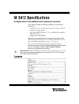
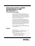
UM10756 EM783 frequently asked questions (FAQ) Rev. 1.1 — 17 December 2013 Document information Info Content Keywords EM783, FAQ, Metrology Abstract Frequently asked questions on EM783 User manual UM10756 NXP Semiconductors EM783 frequently asked questions (FAQ) Revision history Rev Date Description 1.1 20131217 Corrected “EM783 app note” to “EM783 SDK user manual”. 1.0 20131015 Initial version Contact information For more information, please visit: http://www.nxp.com For sales office addresses, please send an email to: [email protected] UM10756 User manual All information provided in this document is subject to legal disclaimers. Rev. 1.1 — 17 December 2013 © NXP B.V. 2013. All rights reserved. 2 of 14 UM10756 NXP Semiconductors EM783 frequently asked questions (FAQ) 1. Introduction EM783 is the next generation e-metering chip with a built-in metrology engine. EM783 is built around a low-power, cost-effective and industry standard ARM Cortex-M0 core. The ARM Cortex-M0 runs with a speed up to 48 MHz and offers 4 kB of EEPROM, 32 kB of flash memory, 8 kB of SRAM and various serial peripherals. For design flexibility, NXP offers multiple variants of EM783 as single-channel (SC), multi-channel (MC), single-phase (SP) and three-phase (TP). The variant chips are: EM783-MC3 EM783-MC6 EM783-SC EM783-SP EM783-TP The EM783 reference design evaluation module (EVM) includes an SDK package consisting of a reference energy meter application and metrology library in binary format. The metrology library provides the interface to the EM783 metrology engine. The SDK package is available for download from the NXP website. This document provides details on using EM783 in question and answer format. 1.1 Key applications Smart plugs and plug meters Single-phase residential meters DALI/DMX and KNX nodes with metering functionality Industrial sub-meters Power monitors for servers Smart appliances 1.2 Block diagram Metrology Engine with Net Frequency Tracking Cortex-M0 50 MHz 4 kB EEPROM 8 kB SRAM 32 kB Flash Advanced Peripheral Bus Temperature Sensor 1 x SPI 1 x I2C 1 x UART RS485/IrDA aaa-009758 Fig 1. UM10756 User manual EM783 block diagram All information provided in this document is subject to legal disclaimers. Rev. 1.1 — 17 December 2013 © NXP B.V. 2013. All rights reserved. 3 of 14 UM10756 NXP Semiconductors EM783 frequently asked questions (FAQ) 1.3 Disclaimer The EM783 EVM is a prototype only for demonstration and evaluation purposes. Improper use of the EVM can result in electrical shock and fire hazard due to the operational voltages and currents of the EVM. Ensure that only qualified personnel familiar with the risks and hazards associated with high voltages and currents handle the EVM. Do not touch the EVM or its components when the EVM is energized. Fig 2. Caution 1.4 Support information Use the following link for additional information on EM783: http://www.nxp.com/products/power_management/energy_measurement_ics/series/EM7 83.html Send an email to [email protected] for technical support on EM783. UM10756 User manual All information provided in this document is subject to legal disclaimers. Rev. 1.1 — 17 December 2013 © NXP B.V. 2013. All rights reserved. 4 of 14 UM10756 NXP Semiconductors EM783 frequently asked questions (FAQ) 2. EM783 frequently asked questions 2.1 EM783 specification 2.1.1 What is the accuracy of EM783? The table below lists the accuracy of the energy measurements provided by the different variants of the EM783. Table 1. Variant 2.1.2 EM783 Accuracy Accuracy (%) Dynamic range MC3 1 1000 SC 1 1000 SP 1 1000 MC6 2 50 TP 2 50 What is the accuracy of the frequency measurement? 0.01% is the accuracy of frequency measurement. 2.1.3 What is the range of current that can be measured with EM783? The analog front end design (AFE) determines the range of current that can be measured using EM783. The AFE scales the input voltage and current signals to a voltage signal in the range from VSS to VDD at EM783 inputs. EM783 samples this signal and provides the metrology data. 2.1.4 Up to which harmonic can EM783 measure? EM783 can measure up to 64th harmonic. 2.2 Metrology engine software interface 2.2.1 Is the metrology engine software source code available? No. Metrology engine software for EM783 is provided only in the binary form as a library. The interfaces provided by the metrology engine software and the API call sequence are detailed in EM783_API.pdf. The API document can be downloaded from the EM783 support website. 2.2.2 What are the interfaces provided by the metrology engine software? Refer to EM783_API.pdf. 2.2.3 How are the initial values computed for the calibration data supplied to the metrology engine software using metrology_ranges_t structure? The calibration data supplied to the metrology engine software via the metrology_ranges_t structure are: 1. Vpp: This parameter represents the maximum peak-to-peak value of the AC voltage signal at the input of the AFE that produces a voltage signal with a peak-to-peak value of VDD at the EM783 input. The value of this parameter depends on the transfer function of the AFE circuitry. Its value is at least: Vpp V max* 2 * 2 UM10756 User manual All information provided in this document is subject to legal disclaimers. Rev. 1.1 — 17 December 2013 (1) © NXP B.V. 2013. All rights reserved. 5 of 14 UM10756 NXP Semiconductors EM783 frequently asked questions (FAQ) In practice, the circuit design ensures that the maximum peak-to-peak input voltage results only in a peak-to-peak voltage swing between 5% and 95% of VDD at the EM783 input (this is to avoid operating in the non-linear regions of the opamps). Consider the following sample design for 220 V AC mains: Max input voltage Vmax (RMS): 260 V; VDD: 3.3 V Maximum peak value of the input voltage: 260 x √2 = 367.7 V. 95% of VDD: 0.95 x 3.3 = 3.135 V 367.7 V peak input AC voltage produces a signal with a peak of 3.135 V at the EM783 input. Hence, for a peak of 3.3 V at the EM783 input, the peak value of the input voltage must be: (3.3 x 367.7) ÷ 3.135 =387.05 V. Therefore, the initial value for the range parameter = 2 x 387.05 = 774.1 V. 2. Ipp: This parameter represents the maximum peak-to-peak value of the AC current signal at the input of the AFE that produces a voltage signal with a peak-to-peak value of VDD at the EM783 input. The value of this parameter depends on the transfer function of the AFE circuitry. The high-gain current channel is designed to measure the current in the range of 0 to (Imax ÷ 32). Its value is at least: Ipp( high _ gain ) ( Imax / 32)* 2 * 2 (2) In practice, the circuit design ensures that the maximum peak-to-peak input voltage results only in a peak-to-peak voltage swing between 5% and 95% of VDD at the EM783 input (this is to avoid operating in the non-linear regions of the opamps). Consider the following sample design: a. 220 V AC mains b. Max RMS current to be measured, Imax: 70 A c. Gain of the high-gain channel: 32 d. VDD: 3.3 V Maximum peak value of the input current: 70 / 32 x √2 = 3.09 A. 95% of VDD: 0.95 x 3.3 = 3.135 V 3.09 A peak input AC current produces a signal with a peak of 3.135 V at the EM783 input. Hence, for a peak of 3.3 V at the EM783 input, the peak value of the input current must be: 3.3 x 3.09 ÷ 3.135 = 3.253 A. Therefore, the initial value for the range parameter = 2 x 3.253 = 6.506 A. The low-gain current channel is designed to measure a maximum current of Imax. Hence, the initial value of the calibration parameter for the low-gain channel is: 32 x 6.506 = 208.192 A. 3. Delta Phi: This parameter represents the phase angle error between the voltage and the current signals for a channel with a pure resistive load. The initial value of this parameter is set to 0. UM10756 User manual All information provided in this document is subject to legal disclaimers. Rev. 1.1 — 17 December 2013 © NXP B.V. 2013. All rights reserved. 6 of 14 UM10756 NXP Semiconductors EM783 frequently asked questions (FAQ) 2.2.4 What is the recommended value for integration period parameter for the metrology engine initialization? The recommended value of integration period parameter for the metrology engine is between 45 and 130 mains periods (inclusive). 2.2.5 What do the following members in metrology_result_t denote: vphigh, vplow, iphigh, iplow? These fields indicate the maximum positive and negative peak values of the voltage and current signals during the last integration period. These values are used in the offset calibration. 1. vphigh – maximum positive peak of the input voltage signal. 2. vplow – maximum negative peak of the input voltage signal. 3. iphigh – maximum positive peak of the input current signal. 4. iplow – maximum negative peak of the input current signal. 2.2.6 What is metrology_offset_t structure used for? The data supplied by the metrology_offset_t structure are used to compensate for the opamp input offset errors. 2.2.6.1 How are the values computed for the offset data supplied to the metrology engine software using the metrology_set_offsets API? The detailed steps to determine the value of the offsets for all the voltage and current channels are listed in the section “Calibration of offsets” in the EM783 SDK user manual. vphigh, vplow, iphigh, iplow members of metrology_result_t are used for the offset calibration. Summary of the steps to determine the offsets is as follows: 1. Supply the voltage input from an AC source to the voltage input of EM783 EVM. 2. Observe the values of positive and negative voltage peaks. 3. If the value of positive peak is equal to the negative peak, offset value for the channel is 0. 4. If the value of positive and negative peak values are not equal, then the offset parameter is computed as follows: (3) Offset [(Vphigh Vplow ) / 2] 5. Apply the offset and ensure that both positive and negative peaks have the same value. 2.2.7 What is the sampling frequency of the metrology engine? Metrology engine samples at 6.4 ksps. 2.2.8 How does EM783 metrology engine select between the high-gain and lowgain channels? EM783 metrology engine samples both the high-gain and low-gain channels simultaneously and combines the data to generate the metrology results for the current input. 2.2.8.1 Are external components such as relays required for the channel selection? No external hardware components are required on the board to select between the highgain and low-gain channels. UM10756 User manual All information provided in this document is subject to legal disclaimers. Rev. 1.1 — 17 December 2013 © NXP B.V. 2013. All rights reserved. 7 of 14 UM10756 NXP Semiconductors EM783 frequently asked questions (FAQ) 2.2.9 What is the shortest response time (time at which the measurement results are available) of the metrology engine? The metrology engine integration duration is configurable from 45 to 130 mains periods. The metrology result is available only at the end of every integration period. Hence, the integration period is the shortest response time of the metrology engine. For example: For 220 V/50 Hz mains system with integration period configured to 130 mains periods, the metrology results will be available every 2.6 s (130 * (1÷50)). 2.2.10 Does the accuracy of the metrology engine calibrated with 220 V/50 Hz mains remain intact when the system is used with 110 V/60 Hz mains? No. The unit needs recalibration with 110 V/60 Hz mains input to achieve the desired accuracy. 2.3 SDK for EM783 2.3.1 Where can the EM783 SDK package be downloaded from? EM783 SDK package can be downloaded from the EM783 support website. 2.3.2 What toolchains and debuggers does the EM783 SDK support? EM783 1.0 EVM is tested with the following toolchain-debugger combinations: Table 2. EM783 SDK toolchain list Toolchain Debugger Keil uVision 4.60.0.0 ULINK2 2.4 Calibration 2.4.1 What is the procedure used to calibrate the metrology engine? Refer to the calibration section of the EM783 SDK user manual available at the EM783 support website. 2.4.2 Does the metrology firmware require upgrading when the analog front end components are modified? No. The metrology firmware need not be upgraded, if the analog frontend is re-designed for a different current range. The unit requires only recalibration. 2.5 Analog front end design 2.5.1 Why are two gain channels used for a single current input in MC3, SC and SP variants? MC3, SC and SP variants of EM783 use two gain channels for a single current input to achieve the accuracy and the dynamic range listed in Table 1. 2.5.2 Does the phase of the voltage and current inputs require matching on the AFE? No. The voltage and the current signal phases need not be matched by the AFE circuitry. Instead, the calibration procedure corrects for the phase difference between the two signals. Refer to the calibration section of the EM783 SDK user manual for more details on phase correction. UM10756 User manual All information provided in this document is subject to legal disclaimers. Rev. 1.1 — 17 December 2013 © NXP B.V. 2013. All rights reserved. 8 of 14 UM10756 NXP Semiconductors EM783 frequently asked questions (FAQ) 2.5.3 Why does the metrology engine report the active power as a negative quantity? The active power is computed as a negative quantity, if: 1. The CT terminal connections to the AFE are reversed. 2. The direction of current flow from the source to the load through the CT is reversed. 2.5.4 How are the unused inputs of opamps connected? For minimum opamp power consumption, 1. Connect the positive input of the opamp to VDD/2 through a resistive divider network (using two 1 MΩ resistors). 2. Tie the negative input of the opamp to the opamp output. 2.5.5 Does the burden resistor require specific placement? Place the burden resistor as close to the opamp as possible. Also, ensure that the trace connecting the current transformer (CT) to the burden resistor is as short as possible. 2.5.6 What should be the upper limit on the board noise level to achieve the desired accuracy? To meet the desired accuracy and dynamic range, the PCB noise level should not exceed 10 mVpp. 2.5.7 Does the opamp feedback components require specific placement? Place the opamp feedback components as close to the opamps as possible. UM10756 User manual All information provided in this document is subject to legal disclaimers. Rev. 1.1 — 17 December 2013 © NXP B.V. 2013. All rights reserved. 9 of 14 UM10756 NXP Semiconductors EM783 frequently asked questions (FAQ) 3. Legal information 3.1 Definitions Draft — The document is a draft version only. The content is still under internal review and subject to formal approval, which may result in modifications or additions. NXP Semiconductors does not give any representations or warranties as to the accuracy or completeness of information included herein and shall have no liability for the consequences of use of such information. 3.2 Disclaimers Limited warranty and liability — Information in this document is believed to be accurate and reliable. However, NXP Semiconductors does not give any representations or warranties, expressed or implied, as to the accuracy or completeness of such information and shall have no liability for the consequences of use of such information. In no event shall NXP Semiconductors be liable for any indirect, incidental, punitive, special or consequential damages (including - without limitation lost profits, lost savings, business interruption, costs related to the removal or replacement of any products or rework charges) whether or not such damages are based on tort (including negligence), warranty, breach of contract or any other legal theory. Notwithstanding any damages that customer might incur for any reason whatsoever, NXP Semiconductors’ aggregate and cumulative liability towards customer for the products described herein shall be limited in accordance with the Terms and conditions of commercial sale of NXP Semiconductors. Right to make changes — NXP Semiconductors reserves the right to make changes to information published in this document, including without limitation specifications and product descriptions, at any time and without notice. This document supersedes and replaces all information supplied prior to the publication hereof. Suitability for use — NXP Semiconductors products are not designed, authorized or warranted to be suitable for use in life support, life-critical or safety-critical systems or equipment, nor in applications where failure or malfunction of an NXP Semiconductors product can reasonably be expected to result in personal injury, death or severe property or environmental damage. NXP Semiconductors accepts no liability for inclusion and/or use of NXP Semiconductors products in such equipment or applications and therefore such inclusion and/or use is at the customer’s own risk. Applications — Applications that are described herein for any of these products are for illustrative purposes only. NXP Semiconductors makes no representation or warranty that such applications will be suitable for the specified use without further testing or modification. whether the NXP Semiconductors product is suitable and fit for the customer’s applications and products planned, as well as for the planned application and use of customer’s third party customer(s). Customers should provide appropriate design and operating safeguards to minimize the risks associated with their applications and products. NXP Semiconductors does not accept any liability related to any default, damage, costs or problem which is based on any weakness or default in the customer’s applications or products, or the application or use by customer’s third party customer(s). Customer is responsible for doing all necessary testing for the customer’s applications and products using NXP Semiconductors products in order to avoid a default of the applications and the products or of the application or use by customer’s third party customer(s). NXP does not accept any liability in this respect. Export control — This document as well as the item(s) described herein may be subject to export control regulations. Export might require a prior authorization from competent authorities. Evaluation products — This product is provided on an “as is” and “with all faults” basis for evaluation purposes only. NXP Semiconductors, its affiliates and their suppliers expressly disclaim all warranties, whether express, implied or statutory, including but not limited to the implied warranties of noninfringement, merchantability and fitness for a particular purpose. The entire risk as to the quality, or arising out of the use or performance, of this product remains with customer. In no event shall NXP Semiconductors, its affiliates or their suppliers be liable to customer for any special, indirect, consequential, punitive or incidental damages (including without limitation damages for loss of business, business interruption, loss of use, loss of data or information, and the like) arising out the use of or inability to use the product, whether or not based on tort (including negligence), strict liability, breach of contract, breach of warranty or any other theory, even if advised of the possibility of such damages. Notwithstanding any damages that customer might incur for any reason whatsoever (including without limitation, all damages referenced above and all direct or general damages), the entire liability of NXP Semiconductors, its affiliates and their suppliers and customer’s exclusive remedy for all of the foregoing shall be limited to actual damages incurred by customer based on reasonable reliance up to the greater of the amount actually paid by customer for the product or five dollars (US$5.00). The foregoing limitations, exclusions and disclaimers shall apply to the maximum extent permitted by applicable law, even if any remedy fails of its essential purpose. 3.3 Trademarks Notice: All referenced brands, product names, service names and trademarks are property of their respective owners. Customers are responsible for the design and operation of their applications and products using NXP Semiconductors products, and NXP Semiconductors accepts no liability for any assistance with applications or customer product design. It is customer’s sole responsibility to determine UM10756 User manual All information provided in this document is subject to legal disclaimers. Rev. 1.1 — 17 December 2013 © NXP B.V. 2013. All rights reserved. 10 of 14 UM10756 NXP Semiconductors EM783 frequently asked questions (FAQ) Notes UM10756 User manual All information provided in this document is subject to legal disclaimers. Rev. 1.1 — 17 December 2013 © NXP B.V. 2013. All rights reserved. 11 of 14 UM10756 NXP Semiconductors EM783 frequently asked questions (FAQ) 4. List of figures Fig 1. Fig 2. EM783 block diagram ....................................... 3 Caution.............................................................. 4 UM10756 User manual All information provided in this document is subject to legal disclaimers. Rev. 1.1 — 17 December 2013 © NXP B.V. 2013. All rights reserved. 12 of 14 UM10756 NXP Semiconductors EM783 frequently asked questions (FAQ) 5. List of tables Table 1. Table 2. EM783 Accuracy ............................................... 5 EM783 SDK toolchain list.................................. 8 UM10756 User manual All information provided in this document is subject to legal disclaimers. Rev. 1.1 — 17 December 2013 © NXP B.V. 2013. All rights reserved. 13 of 14 UM10756 NXP Semiconductors EM783 frequently asked questions (FAQ) 6. Contents 1. 1.1 1.2 1.3 1.4 2. 2.1 2.1.1 2.1.2 Introduction ......................................................... 3 Key applications ................................................. 3 Block diagram .................................................... 3 Disclaimer .......................................................... 4 Support information ............................................ 4 EM783 frequently asked questions .................... 5 EM783 specification ........................................... 5 What is the accuracy of EM783?........................ 5 What is the accuracy of the frequency measurement? ................................................... 5 2.1.3 What is the range of current that can be measured with EM783? ..................................... 5 2.1.4 Up to which harmonic can EM783 measure? ..... 5 2.2 Metrology engine software interface .................. 5 2.2.1 Is the metrology engine software source code available? ........................................................... 5 2.2.2 What are the interfaces provided by the metrology engine software? ............................... 5 2.2.3 How are the initial values computed for the calibration data supplied to the metrology engine software using metrology_ranges_t structure?... 5 2.2.4 What is the recommended value for integration period parameter for the metrology engine initialization?....................................................... 7 2.2.5 What do the following members in metrology_result_t denote: vphigh, vplow, iphigh, iplow? ................................................................. 7 2.2.6 What is metrology_offset_t structure used for? .. 7 2.2.6.1 How are the values computed for the offset data supplied to the metrology engine software using the metrology_set_offsets API? ......................... 7 2.2.7 What is the sampling frequency of the metrology engine? .............................................................. 7 2.2.8 How does EM783 metrology engine select between the high-gain and low-gain channels? . 7 2.2.8.1 Are external components such as relays required for the channel selection? .................................. 7 2.2.9 What is the shortest response time (time at which the measurement results are available) of the metrology engine? ........................................ 8 2.2.10 Does the accuracy of the metrology engine calibrated with 220 V/50 Hz mains remain intact when the system is used with 110 V/60 Hz mains? ............................................................... 8 2.3 SDK for EM783 .................................................. 8 2.3.1 Where can the EM783 SDK package be 2.3.2 2.4 2.4.1 2.4.2 2.5 2.5.1 2.5.2 2.5.3 2.5.4 2.5.5 2.5.6 2.5.7 3. 3.1 3.2 3.3 4. 5. 6. downloaded from? ..............................................8 What toolchains and debuggers does the EM783 SDK support? .....................................................8 Calibration ..........................................................8 What is the procedure used to calibrate the metrology engine? ..............................................8 Does the metrology firmware require upgrading when the analog front end components are modified? ............................................................8 Analog front end design......................................8 Why are two gain channels used for a single current input in MC3, SC and SP variants? ........8 Does the phase of the voltage and current inputs require matching on the AFE? ............................8 Why does the metrology engine report the active power as a negative quantity? ............................9 How are the unused inputs of opamps connected? .........................................................9 Does the burden resistor require specific placement? .........................................................9 What should be the upper limit on the board noise level to achieve the desired accuracy? .....9 Does the opamp feedback components require specific placement? ............................................9 Legal information ..............................................10 Definitions.........................................................10 Disclaimers .......................................................10 Trademarks ......................................................10 List of figures .....................................................12 List of tables ......................................................13 Contents .............................................................14 Please be aware that important notices concerning this document and the product(s) described herein, have been included in the section 'Legal information'. © NXP B.V. 2013. All rights reserved. For more information, please visit: http://www.nxp.com For sales office addresses, please send an email to: [email protected] Date of release: 17 December 2013 Document identifier: UM10756