1
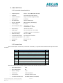
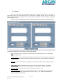
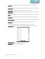
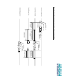
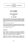
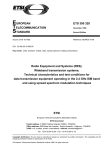
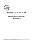
M433LC Radio Modem
(ETSI 300-220)
Technical Manual
ISSUE : 4.0
UPDATE : 19/08/2002
Adcon RF Technology SA
Les Cardoulines - Bâtiment B4
1360 route des Dolines
06560 Valbonne
Sophia Antipolis - France
Tel.: +33 (0)4 97 21 33 10
Fax : +33 (0)4 97 21 33 11
www.adcon.com
[email protected]
Proprietary Notice:
The information in this document is subject to change without notice.
Company or product names mentioned in this document may be trademarks or registered trademarks of their
respective companies.
All rights reserved. Neither the whole nor any part of the information contained in this publication may be reproduced
in any material form except with the written permission of Adcon RF Technology.
This publication is intended only to assist the reader in the use of the product. Adcon RF Technology. shall not be liable
for any loss or damage arising from the use of any information in this publication, or any error or omission in such
information, or any incorrect use of the product.
Copyright Adcon RF Technology 2002
M433LC-Ind Modem Technical Manual
Rev: 4.0
Page: 2
TABLE OF CONTENTS
TABLE OF CONTENTS--------------------------------------------------------------------------------------------------3
1. INTRODUCTION-------------------------------------------------------------------------------------------------------4
1.1 Aim of Document ------------------------------------------------------------------------------------------------------------ 4
1.2 LC-Ind Modem overview -------------------------------------------------------------------------------------------------- 4
1.3 MTC Software Installation------------------------------------------------------------------------------------------------ 4
2. DESCRIPTION-----------------------------------------------------------------------------------------------------------5
2.1 Technical characteristics--------------------------------------------------------------------------------------------------- 5
2.2 Connections -------------------------------------------------------------------------------------------------------------------- 5
2.3 Diagrams------------------------------------------------------------------------------------------------------------------------- 7
3. BASIC OPERATION: USING MTC ------------------------------------------------------------------------------8
3.1 The desktop -------------------------------------------------------------------------------------------------------------------- 8
3.1.1 The menu bar----------------------------------------------------------------------------------------------------- 10
3.1.2 The tool bar ------------------------------------------------------------------------------------------------------- 12
3.1.3 The application Tree-------------------------------------------------------------------------------------------- 13
3.2 Peer-to-peer dialog ------------------------------------------------------------------------------------------------------- 15
3.2.1 Configuration ----------------------------------------------------------------------------------------------------- 15
3.2.2 Dialog--------------------------------------------------------------------------------------------------------------- 16
4. ADVANCED OPERATION ---------------------------------------------------------------------------------------18
4.1 Transparent mode --------------------------------------------------------------------------------------------------------- 18
4.2 Hayes or ‘AT’ Mode------------------------------------------------------------------------------------------------------- 20
4.2.1 General concept ------------------------------------------------------------------------------------------------- 20
4.2.2 Standard commands-------------------------------------------------------------------------------------------- 21
4.3 Register description ------------------------------------------------------------------------------------------------------ 22
Appendix : History -----------------------------------------------------------------------------------------------------23
A.1 Revision history------------------------------------------------------------------------------------------------------------- 23
A.2 Firmware version history ----------------------------------------------------------------------------------------------- 23
Copyright Adcon RF Technology 2002
M433LC-Ind Modem Technical Manual
Rev: 4.0
Page: 3
1. INTRODUCTION
1.1 Aim of Document
The objective of the present document is detail the features, application and operation of the LC-Ind
radio modem.
After introductions about the products and the test and configuration software (MTC Work bench), the
operation of the modems will be described in two distinct parts:
•
The ‘Basic operation’ chapter describes the MTC workbench operation
•
The ‘Advanced operation’ is more dedicated to the users who want to program and configure the
modem directly. It states all the available commands and registers and gives some operation examples.
A second set of appendix gives additional information about operation, standard and product’s history.
1.2 LC-Ind Modem overview
The LC RF-Modem is a module which is composed of :
•
A control / command part including programmable EEPROM(permanent memory)
•
A radio part (transmission / reception).
The LC-Ind radio modem is a FSK half-duplex FM radio transceiver (data transmission and reception). The
LC-Ind operates in the 433 MHz frequency band, in compliance with the ETSI 300-220 European regulation.
Operating a 10 mW radiated power, LC-Ind modems can be used without any license.
The LC-Ind modem is based on synthesised frequency (maximum of 10 channels with a 175 KHz spacing)
in order to operate in any condition and in most environments.
Numerous parameters such as transmission rates (serial and radio links), radio channel, data format, etc,
can be programmed via the serial link, using Hayes (or ‘AT’) commands. Those programmed parameters, i.e. the
modem’s configuration, are stored within EEPROM’s registers so that LC-Ind modems are automatically
configured with the lastly saved configuration (channel, data rates, etc) when switched on.
By default, the standard configuration is: 9600 bauds, 8 data bits, 1 stop bit, no parity, channel ‘0’,
transparent mode.
1.3 MTC Software Installation
1. Put Adcon database CD into the PC. The CD is autolaunched and displays a browser on the Adcon database
presentation page.
2. Go to the Adcon database page by clicking either on the “Adcon RF Database” link or on its button.
3. Install the MTC Workbench software by clicking on the “MTC Workbench Installation” link. The software is
automatically installed in “C:\Program File\Adcon\MTC\” (this directory can be changed).
Copyright Adcon RF Technology 2002
M433LC-Ind Modem Technical Manual
Rev: 4.0
Page: 4
2. DESCRIPTION
2.1 Technical characteristics
•
Frequency Band :
433,05 – 434,79 MHz (ETSI 300-220)
•
Channels :
10 channels (175 KHz spacing)
•
Channel selection :
Hayes Commands (Register S200)
•
Radio Speed :
9.6 Kbits/s
•
Serial Baudrate:
1200 to 38400 bauds
•
Modul. / Demodul. :
FSK (Frequency Shift Keying)
•
Power Supply:
8 to 40 V
•
RF Consumption (12V) :
• Reception: < 40 mA
• Transmission: < 70 mA
•
RF Sensitivity :
-95 dBm / 50 Ohms
•
RSSI trigger :
YES , Threshold at -93 (±2) dBm
•
RF radiated power :
+10 dBm ( 10 mW ) in transmission
•
Data error rating :
10-4 for -90 dBm
•
Communication range:
up to 1000 m in free field
•
Operating temperature : 0°C / +50 °C
•
Dimensions:
89 x 64 x 24 mm
•
Weight:
≈ 150 g
2.2 Connections
The connection (DCE connection) to the board is ensured by a 9 points SUB D interface whose pins are linked
as follow:
Pin
1
2
3
4
5
6
7
8
9
Function
(RS232 format, ±12 volts)
(RS232 format, ±12 volts)
Ground
(GND)
(from 8 to 40volts) / 80mA.
Tx
Rx
VDD
Dir.
O
I
The radio modem must be power supplied via the SUB D interface 9 points as follows :
•
Input voltage (Max.):
40V
•
Input voltage (Min.):
8V
•
Reverse voltage:
-40V
•
Load dump :
120V 1ms/100ms
•
Fast transient:
Standard IEC801-4, 2KV
•
Conduction disturbance:
Standard IEC801-6, 10V (RMS)
Copyright Adcon RF Technology 2002
M433LC-Ind Modem Technical Manual
Rev: 4.0
Page: 5
Copyright Adcon RF Technology 2002
M433LC-Ind Modem Technical Manual
Rev: 4.0
Page: 6
64
24
44
2.3 Diagrams
69
89
4xinserts M3
63
Ec helle: 1
3. BASIC OPERATION: USING MTC
3.1 The desktop
The Modem Test & Configuration (MTC) Workbench is an Adcon software framework to
test and configure all modems supplied by Adcon RF Technology.
Several and diversified modems, connected to the PC/workstation via various hardware
interfaces (RS232, RS422, ...), can be tested and configured at the same time. The framework
provides a desktop to display, test and configure multiple modems, including LC-Ind radio modem,
with a standard set of functions, common for each modem.
•
Once launched, the MTC software displays the following desktop and message:
The auto-configuration has to be launched for the software to detect the connected radio
module, i.e. ‘Yes’ has to be pressed.
•
Once the auto-configuration is done (a few minutes, depending on the number of serial
ports), the following desktop is displayed:
•
A visual check that the software detected the radio modem during auto-configuration can be
done by clicking on the COM1 node. The radio modem should appear as a child node in the
Tree window:
The radio modem is now ready to be tested and configured with the different options of the
MTC software. Those options are described below.
Copyright Adcon RF Technology 2002
LC-Ind Modems Technical Manual
Rev: 1.0
Page: 9
3.1.1 The menu bar
The menu bar is fully configurable and is defined in the application configuration file:
Each menu is composed of several submenus corresponding to specific functions or actions.
Every menus and submenus are described in the following paragraphs. Each function and option will be
further described in the next chapters.
The ‘File’ Menu
The ‘File’ menu is composed of ‘Exit’ an submenu which quits the software program.
The ‘Settings’ Menu
The ‘Settings’ menu is composed of the following submenus:
•
Language: Allows the user to change the software’s operation language (English, French and
German are available for the moment). The default language is English.
•
User level: Allows the user to switch from a basic operation desktop to an advanced operation
desktop and vice-versa. The current description concerns the basic user level configuration. For
the advanced user level configuration description, refer to the MTC Workbench User Manual.
The ‘Modem’ Menu
The ‘Modem’ menu is composed of the following submenu:
•
Channel scanning: Displays a window which presents either the radio channel’s occupation rate
or the signal’s level received by the radio module.
•
Autoconfiguration: Allows the user to launch an autoconfiguration on one or on all ports from
the desktop (e.g. for connection loss or modem replacement).
The ‘Peer-to-peer’ Menu
The ‘Peer-to-peer’ menu is for basic operation configuration and is composed of the following
submenus:
•
Configuration: Displays a window allowing quick configuration of two radio modules for peer-topeer dialog. The parameters concerned are the operating mode and the radio channel.
•
Dialog: Displays an advanced terminal dialog window between two given radio modules, the
ports of which are chosen by the user.
Copyright Adcon RF Technology 2002
LC-Ind Modems Technical Manual
Rev: 1.0
Page: 10
The ‘Network’ Menu
The ‘Network’ menu is composed of the following submenus:
•
Configuration: Displays a window allowing quick configuration of two radio modules for network
dialog. The parameters concerned are the operating mode (Network client, server or addressed
secured), the network and clients’ IDs, and the radio channel.
•
Dialog: Displays an advanced terminal dialog window between two given radio modules already
configured with all necessary network parameters (i.e. mode, network and clients’ IDs). The ports
are chosen by the user.
Note:
It is not applicable to M433LC-Ind units.
The ‘Windows’ Menu
The ‘Windows’ menu lists the different windows already opened and allows the user to change
the active window. Note that both ‘Tree’ and ‘About ports’ windows will always appear in that list as
they can not be closed.
The ‘Help’ Menu
The ‘Help’ menu is composed of an ‘About’ submenu which displays a window containing all
information about the software development such as software version, copyright, author, etc:
Copyright Adcon RF Technology 2002
LC-Ind Modems Technical Manual
Rev: 1.0
Page: 11
3.1.2 The tool bar
The tool bar contains shortcut buttons corresponding to the main functions of the menu bar
described in the previous paragraph. Some of those are only applicable in certain conditions and are
therefore disabled elsewhere.
1
2
3
4
The buttons’ functions are listed in the following table.
N°
NAME
1
Channel scanning
2
Auto-configuration
3
Opens peer-to-peer dialog
4
Opens network dialog
FUNCTION / ACTION
Channel scanning of the current radio module
Operates new auto configuration on all or selected ports
Opens peer-to-peer dialog window between two chosen ports
Opens network dialog window between two chosen ports
Copyright Adcon RF Technology 2002
LC-Ind Modems Technical Manual
Rev: 1.0
Page: 12
3.1.3 The application Tree
Once the auto configuration is done, the software builds and displays the application tree using
the serial ports defined in the system, the connected modems detected during auto configuration and the
modem configuration files found in the application configuration file.
The application tree is composed of two windows that can not be closed: the ‘Tree’ window and
the ‘About Ports’ window. They are described below:
Note: The application tree, i.e. the Tree window especially, can not be exploited in basic user level
configuration. In basic level configuration, the Tree is just used as information.
Copyright Adcon RF Technology 2002
LC-Ind Modems Technical Manual
Rev: 1.0
Page: 13
Tree Window
The top part lists the different serial ports and their connected modems when
applicable. Whenever a modem is connected to a port, a node appears at that port.
Clicking on that node will display the modem type as a child node:
The bottom part lists the different configuration files available, sorted by type of
modem. It is not available in basic user level configuration.
Ports Window
The ‘About port’ window gives information about the status of each serial port detected by the
system during auto configuration:
OPEN
Modem connected to corresponding port. Port in use
(E.g. a tool is operating on that port.)
CLOSED
Modem connected to corresponding port. Port not in use
NOT CONNECTED No modem connected to corresponding port
Note:
The legend (i.e. ports status) can be hidden by disabling the ‘Legend’ button.
Copyright Adcon RF Technology 2002
LC-Ind Modems Technical Manual
Rev: 1.0
Page: 14
3.2 Peer-to-peer dialog
The first tool available with the MTC software is the peer-to-peer dialog tool, allowing the user to
communicate between two compatible radio modules. From the menu bar, the ‘Peer-to-peer’ menu is to
be selected.
3.2.1 Configuration
From the menu bar, the ‘Peer-to-peer/Configuration’ submenu has to be selected. A window
allowing the user configuring two compatible radio units for peer-to-peer dialog is displayed:
Both operating mode and communication channel should be chosen by the user. Once the
configuration is done, pressing ‘OK’ or ‘DIALOG’ allows the user to validate it:
If ‘OK’ was pressed, pressing ‘Yes’ quits the peer-to-peer configuration window and the user has
then to select the peer-to-peer dialog tool either from the menu bar or the tool bar. If ‘DIALOG’ was
pressed, pressing ‘Yes’ opens the peer-to-peer dialog window (See paragraph 7.2). Pressing ‘No’ cancels
the configuration in both cases.
Copyright Adcon RF Technology 2002
LC-Ind Modems Technical Manual
Rev: 1.0
Page: 15
3.2.2 Dialog
From the menu bar, the ‘Tool/Peer-to-peer dialog’ (Advanced user level) or the ‘Peer-topeer/Dialog’ (Basic user level) submenu has to be selected. A window allowing the user choosing on
which ports the peer-to-peer dialog tool has to be operated is displayed. The same window is displayed
when using the tool bar.
Once the choice is validated by the user, the following peer-to-peer dialog window is displayed:
The peer-to-peer dialog window is composed of two identical panels, one for each module. The
different fields and buttons of those panels are described below:
•
Title: displayed on top of the panel, it gives the type of module and the port it is connected to
(E.g. 433-LC@COM1).
•
‘Received data’: This non-editable field displays the data received on the radio link from the other
module. The red dot indicates the status of the communication: it goes to green if a message is
being received.
•
‘Nb msg’: Provides the number of messages received by the module since the beginning of the
dialog.
•
‘Data to send’: Displays the data to be sent by the user to the other module. The red dot
indicates the status of the communication: it goes to green when a message is being sent.
•
‘Frame length’: Provides the length of the frame to be sent by the user.
•
‘Send continuously’: Enabling this option allows the user to transmit data (from ‘Data to send’)
permanently to the other modem. The time out (i.e. ‘Each […] ms’ field) is configurable but
should be greater than 500 ms.
Copyright Adcon RF Technology 2002
LC-Ind Modems Technical Manual
Rev: 1.0
Page: 16
•
‘Auto reply’: Enabling this option allows the user to send every received frame back to the
transmitter.
•
‘Not received’: Indicates the number of messages that were not received by the unit during the
dialog.
•
‘Nb msg sent’: Provides the number of messages sent to the other module.
•
‘Elapsed time’: Specifies how long the modem has been transmitting when the send continuously
option is enabled.
•
‘Errors’: Provides the number of errors occurring during a transmission. Those errors are counted
in characters.
•
‘Send’ button: Sends the frame previously entered by the user in the ‘data to send’ field to the
other module.
•
‘Clear Send’ button: Clears the ‘data to send’ field as well as the ‘received data’ field of the other
module.
•
‘Stop’ button: Stops a permanent transmission (when ‘send continuously’ is enabled).
The two other buttons at the bottom of the window are general for both modules:
•
‘Display’ button: Displays a summary of the dialog established between the two radio units:
•
‘Clear All’ button: Clears all the window’s fields (described above).
•
‘Exit’ button: Quits the peer-to-peer dialog window.
Copyright Adcon RF Technology 2002
LC-Ind Modems Technical Manual
Rev: 1.0
Page: 17
4. ADVANCED OPERATION
4.1 Transparent mode
In Transparent Mode, the LC-Ind radio modem behaves like a wired serial link : I.e. LCInd radio modem does not only transmit to the radio channel every serial link received data, but also
transmits on the serial link the radio channel received information.
Basically, the LC-IND radio modem, as a half-duplex module, reproduces the half-duplex
function of a RS-485 cable.
In Transparent Mode, no frame control is performed by the LC-IND radio modem, neither on
the serial link, nor on the radio link. Flow control must be carried out by software applications via
protocols in use such as MODBUS, JBUS, etc…
Consequently, Transparent Mode does not give any possibility to change the module
parameters without a temporary return to Hayes mode.
NOTE: The user’s software application must adequately verify that all buffers are transmitted
correctly taking into account that an interrupted transmission link may lead to losing one or several
buffers.
The transparent mode does not involve the absence of delay in transmission / reception.
The time for UART reception of the first character to be transmitted must be taken into account as
well as the time for carrier synchronisation preamble, time for radio transmission and time for the
transmission into the UART of the receiver.
The total delay between the character transmission on the serial link of an LC RF-Modem and
the reception of the first character on the serial link of another LC RF-Modem must not exceed 25
ms for a serial link at 9600 Baud.
Priority to transmission
The LC RF-Modem takes priority over the reception of the characters coming from the serial link
connected to it. Thus a permanent reception or jamming on its channel of a radio signal (valid or not)
cannot involve locking to switch to Hayes command.
Copyright Adcon RF Technology 2002
LC-Ind Modems Technical Manual
Rev: 1.0
Page: 18
Serial data
Rx/TX switch :
5,5 ms
Carrier detect
Carrier standard time
15 ms
Data No.2...
Data No.1
Transmission / Reception of a data frame in Transparent Mode
RS-232 transmission :
Radio Transmission :
Radio Reception :
RS-232 Reception :
Data No.1
Data No.2
Time-Out : 5 ms
(Register S214)
End carrier process
Data No.1
Data No.2...
4.2 Hayes or ‘AT’ Mode
4.2.1 General concept
Hayes or 'AT' commands comply with Hayes protocol used in PSTN modem standards. This
‘AT’ protocol or Hayes mode is used to program the modem parameters, based on the following
principle:
A data frame always begins with the 2 ASCII ’AT’ characters, standing for
‘ATtention’;
Commands are coded over one or several characters and may include additional
data.
A given command always ends up with a <CR> Carriage Return
A
T
Command
Additional command
...
<CR>
The only exception to this data-framing rule is the switching command from ‘Transparent
Mode’ to ‘AT Mode’. In this case only, the escape code (‘+++’ by default) must be started and
followed by a silent time at least equal to the time out. In this case only <AT> and <CR> shall not be
used.
Note: The Time between 2 characters of the same command must be under 10 seconds.
Despite its similarity to standard telecommunication modem, ADCON LC-IND radio modems
remains a radio link modem and is consequently fitted with some particular additional “AT”
commands proper to radio transmission (I.e. Channel choice, reception level, etc).
The modem response is as follow:
Modem response
Code
OK
‘0’
Error
‘3’
4.2.2 Standard commands
Command
ATO
+++
Description
Operating mode
Activate transparent Mode
“ATO” sets up the Module to transparent mode. To return to Hayes Mode, enter a
‘+++’ sequence.
Activate 'AT' Mode.
“+++” Gives an instant access to the modem parameter set-up mode (AT or Hayes
Mode). ‘+++’ Command shall not be started with AT and ended by <CR>, but
entered between a silent time duration (time-out) which parameter is defined in
milliseconds in Register S214 (i.e. <time-out>’+++’<time-out>).
Note: By activating the ‘AT’ Mode, LC-IND modems inactivate radio reception.
Register Handling
ATSn?
Display of Register S Number N contents.
LC-IND modems operating parameters are stored in ‘S’ classified Registers. S
Registers are numbered from 0 to 512. Some parameters are standard for every
Hayes type modems, other are specific to LC-IND units.
ATSn=m
Entering m value into Register S – Number n.
A new parameter entered is Register S is automatically stored in the modem EEPROM
memory.
AT/S
Clear Display of Significant Registers contents.
Every significant register for the modem (radio configuration, Serial configuration,
operating Mode,) are sent to the serial link, ready to be clearly displayed by a Software
such as Windows «Terminal».
AT/V
Clear Display of the Modem Software version.
Information concerning the version number and installation date is sent on the Serial Link
in clear; ready to be displayed by Software such as Windows «Terminal».
Test Functions
ATTO
Pure carrier transmission (for testing purposes)
ATT1
F0 modulated carrier transmission (for testing purposes)
ATT2
F1 modulated carrier transmission (for testing purposes)
ATT3
Alternative F0-F1 modulated carrier transmission (for testing purposes)
Copyright Adcon RF Technology 2002
LC-Ind Modems Technical Manual
Rev: 1.0
Page: 21
4.3 Register description
LC-Ind modems can offer several possible configurations, using a set of parameters. Those
parameters are located in registers and have a default value. This value can be modified or consulted
through Hayes commands or via the MTC Workbench. The modems’ parameters are stored in the
EEPROM and can therefore be changed up to 10,000 times and be available when switching on the
modem. The registers are listed below:
Access
Registers
Radio Link
Name
Communication
channel N°
R/W
S200
R/W
S210
R/W
S211
Data Length
R/W
S212
Parity
R/W
S213
Number of stop bits
R/W
S214
Time Out
Baudrate
Description
Indicates on which channel the modem is operating.
Included between ‘0’ and ‘9’.
Default value: 0
Indicates the serial link transmission rate:
‘1’: 1200 Baud
'2': 2400 Bauds
'3': 4800 Bauds
'4': 9600 Bauds (Default value)
'5': 19200 Bauds (40 bytes frames max.)
'6': 38400 Bauds (40 bytes frames max.)
Indicates the number of data bits on the serial link
'7': 7 bits.
'8': 8 bits (Default value)
Indicates the parity on the serial link:
'1': None (Default value)
'2': Odd
'3': Even
Indicates the number of stop bits on the serial link
'1': 1 bit (Default value)
'2': 2 bits
Indicates the value of the time-out on the serial link, in ms.
Included between 1 and 255.
Default value: 5 ms
Scanning
R/W
S216
Status format during
scanning (*)
R/W
S23x
Scanning on channel x
R/W
S240
Scanning all channels
R/W
S241
Permanent scanning
Status can be delivered as a binary value or ASCII characters when
answering a scanning:
'0': Binary value is returned (Default value)
'1': ASCII character is returned
Channel N° X (0 to 9) scanning during a selected time multiplied by 10
ms. eturn value is the occupation rate in % of the channel.
Example:
ATS235=20<CR>, stands for a scanning on channel 5 during 20x10 =
200 ms, return value could be :
"=100 " if busy time is 200 ms,(i.e : 100%)
"= 50 " if busy time is 100 ms , (i.e : 50%)
Scans all radio channels, from 0 to 9. For each channel the analysis time
is the given value multiplied by 10 ms.
In ASCII mode the modem answers :
"100;020;000;005;000;000;000;000;000;010" where each figure
separated by ";" represents the occupation rate of a channel, the No.0
(on the left part) to No.9 (on the right part).
In binary Mode, the Modem answers
"=xdy0d00x00" for which each binary character is the occupation rate
of each channel.
Same as order S240 but the channel scanning is permanent. After
scanning 10 channels, the modem transmits the result and starts
immediately a new scanning.
Scanning stops after reception of any character on the serial line .
(*) Scanning = status of the radio activity as noise or data, in the selected channel
Copyright Adcon RF Technology 2002
LC-Ind Modems Technical Manual
Rev: 1.0
Page: 22
Appendix : History
A.1 Revision history
Revision
Date
Author
0.1
1.0
2.0
3.0
4.0
‘98
‘99
‘00
‘01
08/02
GS
GS
MHB
MHB
SG
Subject
Creation
Updates according to development
Updates according to development
Updates and re-design
Updates and MTC integration
A.2 Firmware version history
v 1.51
Serial rate up to 38400 bauds
Radio rate up to 10 Kbits/s
Transparent mode
Scanning
Copyright Adcon RF Technology 2002
LC-Ind Modems Technical Manual
Rev: 1.0
Page: 23