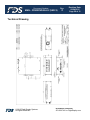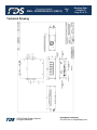
1
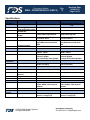
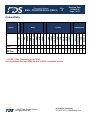
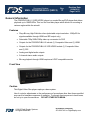
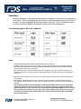
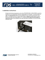
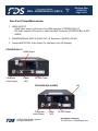
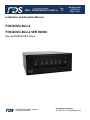
Document Number: Rev: MAN – FD932DVD-BLU-2 (VER X) C Revision Date: 09/24/2015 Page 1 of 31 Installation and Operation Manual FD932DVD-BLU-2 FD932DVD-BLU-2 VER HDSDI Blu-ray/DVD/CD/MP3 Player © 2015 Flight Display Systems. All Rights Reserved. TECHNICAL SUPPORT 470-239-7421 or FlightDisplay.com Document Number: Rev: MAN – FD932DVD-BLU-2 (VER X) C Revision Date: 09/24/2015 Page 2 of 31 Specifications Disc Player Blu-ray / DVD FD932DVD-BLU-2 VER HDSDI (JS) Blu-ray / DVD 1080P/1080i/720p/480p/480i 1080p/1080i/720p 1080p/1080i/720p/576p/576i 1080p/1080i/720p/576i Playback Formats Analog and SPDIF Digital 2-Channel Stereo CD-ROM/DVD-ROM/DVD-R DVD-RW/Audio/CD/CD-R/CDRW VC-1/MPEG2/JPEG/MP3 Analog and SPDIF Digital 2-Channel Stereo CD-ROM/DVD-ROM/DVD-R DVD-RW/Audio/CD/CD-R/CDRW VC-1/MPEG2/JPEG/MP3 Power 28VDC 750mA 28VDC 750mA Inrush Current 14.8 Amps peak 4.0Amps @50µS 0.8 Amp Steady State @100µS 14.8 Amps peak 4.0Amps @50µS 0.8 Amp Steady State @100µS Operating Temperatures 0-50ºC (32-122ºF) 0-50ºC (32-122ºF) External 6.98” (W) x 2.60” (H) x 8.57” (D) 6.98” (W) x 2.60” (H) x 8.57” (D) External w/ Mounting Brackets Weight Materials 8.25” (W) x 2.60” (H) x 8.57” (D) 8.25” (W) x 2.60” (H) x 8.57” (D) 3 lbs. Aluminum 3.3 lbs. Aluminum Menu Control IR, included & 5’ IR Extension Cable, RS485, CAN, Physical Buttons IR, included & 5’ IR Extension Cable, RS485, CAN, Physical Buttons Section 21 Category B Section 7 Category B Section 21 Category B Section 7 Category B FD932DVD-BLU-2 Technology NTSC Supported Formats (59.94/60 Hz) PAL Supported Formats (50 Hz) Audio Outputs Playback Media Power Environmental Conditions Dimensions Features User Manual Qualified Testing RTCA DO-160G © 2015 Flight Display Systems. All Rights Reserved. TECHNICAL SUPPORT 470-239-7421 or FlightDisplay.com Document Number: Rev: MAN – FD932DVD-BLU-2 (VER X) C Revision Date: 09/24/2015 Page 3 of 31 FD932DVDBLU-2 FD932DVDBLU-2 VER HDSDI 1* 1* 1 1 1 1 1 1 1 1 1 * = NTSC or PAL (Depending on the Disc) Blu-ray playback through HDMI requires a HDCP compatible monitor. © 2015 Flight Display Systems. All Rights Reserved. IR REMOTE CAN RS485 CONTROL RS232 3G-SDI HD-SDI COMMUNICATION SD-SDI DVI-D HDMI COMPOSITE S-VIDEO VGA HDSDI DVI-D OUTPUTS HDMI DISPLAY PORT COMP S-VIDEO INPUTS VGA PMA PRODUCT CERTIFICATIONS Connectivity TECHNICAL SUPPORT 470-239-7421 or FlightDisplay.com Document Number: Rev: MAN – FD932DVD-BLU-2 (VER X) C Revision Date: 09/24/2015 Page 4 of 31 Table of Contents General Information ................................................................................................... 6 Features ...................................................................................................................... 6 Front View ................................................................................................................... 6 Discs Supported ......................................................................................................... 7 Installation Instructions ............................................................................................. 8 Power........................................................................................................................... 8 Rear Panel Output ...................................................................................................... 9 Assembly of Connector Spring Latch .................................................................... 10 Video Wiring Suggestions ....................................................................................... 11 Audio Wiring ............................................................................................................. 12 Power and Ground Wiring ....................................................................................... 13 HDMI .......................................................................................................................... 14 Pinout for DB-25 Receptacle ................................................................................... 15 Ship Kit Items ...................................................................................................... 16-17 RS485 Controls ......................................................................................................... 18 Remote Control ........................................................................................................ 19 RS485 Commands .................................................................................................... 20 Infrared Control ........................................................................................................ 21 Operating Instructions ............................................................................................. 22 Operating with Remote ............................................................................................ 23 Special Features ....................................................................................................... 24 Region Codes ........................................................................................................... 25 Technical Drawing ............................................................................................... 26-27 Trouble Shooting ...................................................................................................... 28 Technical Support/Airworthiness ........................................................................... 29 © 2015 Flight Display Systems. All Rights Reserved. TECHNICAL SUPPORT 470-239-7421 or FlightDisplay.com Document Number: Rev: MAN – FD932DVD-BLU-2 (VER X) C Revision Date: 09/24/2015 Page 5 of 31 Warranty .................................................................................................................... 30 Log of Revisions ...................................................................................................... 31 © 2015 Flight Display Systems. All Rights Reserved. TECHNICAL SUPPORT 470-239-7421 or FlightDisplay.com Document Number: Rev: MAN – FD932DVD-BLU-2 (VER X) C Revision Date: 09/24/2015 Page 6 of 31 General Information The FD932DVD-BLU-2 (VER HDSDI) player is a combo Blu-ray/DVD player that allows playback up to 1080P/60Hz. This is a slot load disc player which allows for mounting in various angles within the aircraft. Features Plays Blu-ray High-Definition discs (selectable output resolution: 1080p/60 Hz signals available through HDMI and SDI output only) Selectable 720p/1080i/1080p video up conversion for DVD Outputs for the FD932DVD-BLU-2 include (1) Composite Video and (1) HDMI Outputs for the FD932DVD-BLU-2 VER HDSDI include (1) Composite Video and (1) SDI Analog and digital audio outputs 2-channel stereo audio outputs Blu-ray playback through HDMI requires a HDCP compatible monitor Front View Caution This Digital Video Disc player employs a laser system. Use of controls, adjustments or the performance of procedures other than those specified may result in hazardous exposure to radiation. To prevent direct exposure to laser beam, do not try to open the enclosure. DO NOT STARE INTO BEAM. © 2015 Flight Display Systems. All Rights Reserved. TECHNICAL SUPPORT 470-239-7421 or FlightDisplay.com Document Number: Rev: MAN – FD932DVD-BLU-2 (VER X) C Revision Date: 09/24/2015 Page 7 of 31 Ventilation Slots and openings in the player are provided for ventilation, to ensure correct operation of the product. These openings protect the unit from overheating and must not be blocked or covered. It is recommended that the player have a minimum 1-inch of ventilation around the unit and not be installed in a location that does not have circulating air. The following types of discs are supported Notes: Writeable discs (DVD-RW, DVD-R) must be finalized, VR-mode only. Playback may not work for some types of discs, or when specific operations, such as angle change and aspect ratio adjustment, are being performed. Information about the discs is written in detail on the box. Please refer to this if necessary. Do not allow the disc to become dirty or scratched. Fingerprints, dirt, dust, scratches or deposits of cigarette smoke on the recording surface will disrupt the proper operation and may prevent playback of the disc. MP3 files must be written to the disc with an .mp3 file extension in order to be recognized and played back properly. High bitrate or variable bitrate .mp3 and .wma files may not play back correctly.JPEG picture files must be written to the disc with a .jpeg or .jpg file extension in order to be recognized and played back properly. Due to differing menu formats among Blu-ray and standard DVD-videos, the enter key may be required to start some movies at the home screen, while the play key is required to start other movies at the home screen. This can occur on both Blu-ray and standard DVD movies. If a movie does not start when prompted, try using the enter button if play does not respond, or press the play button if enter does not respond. Again, this is a function of individual Blu-ray and DVD Discs, not the player. © 2015 Flight Display Systems. All Rights Reserved. TECHNICAL SUPPORT 470-239-7421 or FlightDisplay.com Document Number: Rev: MAN – FD932DVD-BLU-2 (VER X) C Revision Date: 09/24/2015 Page 8 of 31 Installation Instructions All cabin entertainment equipment, such as the FD932DVD-BLU-2 (VER HDSDI), should be installed on a non-essential bus and have a dedicated circuit breaker. The units include two angle mounting brackets which can be installed at the top or bottom on each side of the player. The FD932DVD-BLU-2 player also includes a strain relief bracket which is used to secure the HDMI cable in place with a 3/16” cable tie. NOTE: Care should be taken to ensure the units are not installed in an area with poor ventilation, or in an area with excessive heat. © 2015 Flight Display Systems. All Rights Reserved. TECHNICAL SUPPORT 470-239-7421 or FlightDisplay.com Document Number: Rev: MAN – FD932DVD-BLU-2 (VER X) C Revision Date: 09/24/2015 Page 9 of 31 Rear Panel Output/Mechanicals 1. VIDEO OUTPUT HDMI Video output to HD monitor with HDMI connector (FD932DVD-BLU-2) SDI Video output to HD monitor or switch with BNC Connector (FD932DVD-BLU-2 VER HDSDI) 2. POWER/GROUND INPUT & AUDIO OUT, IR Extension, CAN BUS, RS-485 3. Composite/NTSC/PAL Video Output For Interface to Non HD Displays FD932DVD-BLU-2 HDMI Output Composite Video Output Power LED 28 VDC Power FD932DVD-BLU-2-HDSDI Composite Video Output © 2015 Flight Display Systems. All Rights Reserved. Power LED SDI 28 VDC Power TECHNICAL SUPPORT 470-239-7421 or FlightDisplay.com Document Number: Rev: MAN – FD932DVD-BLU-2 (VER X) C Revision Date: 09/24/2015 Page 10 of 31 Assembly of Connector Spring Latch (WPI Interconnect Products P/N 17-529) © 2015 Flight Display Systems. All Rights Reserved. TECHNICAL SUPPORT 470-239-7421 or FlightDisplay.com Document Number: Rev: MAN – FD932DVD-BLU-2 (VER X) C Revision Date: 09/24/2015 Page 11 of 31 Video Wiring Suggestions Avoid routing video wiring parallel to: AC wiring Strobe wiring DC motor supply cables Inverter cabling Or any other potential noise source. The recommended cable for both composite and SDI is PIC 75 Ohm Coax, P/N V75268. This is a lightweight, flexible, and low signal loss cable which meets FAA flammability requirements of FAR 23.1359(d), FAR 25.853(a) and FAR 25.869(a)(4). Similar aviation coaxial cable can be used from other vendors, as well. Some aircraft are prone to AC noise - we recommend adding to the composite source a 75Ohm video isolation transformer such as Deerfield Laboratory, Inc. Part No. 162-1 (www.deerfieldlab.com, (650) 632-4090. In most cases this should be added to the video output of the source. © 2015 Flight Display Systems. All Rights Reserved. TECHNICAL SUPPORT 470-239-7421 or FlightDisplay.com Document Number: Rev: MAN – FD932DVD-BLU-2 (VER X) C Revision Date: 09/24/2015 Page 12 of 31 Audio Wiring for Use with Single Ended Audio Inputs. (i.e.: FDACS) For best performance, use four individual wires or two twisted pairs in a shielded cable. The four audio wires would be connected to Left +, Left -, Right +, Right -. All four wires will run from the Blu-ray player to the destination. Left + and Right + connect to the Left and Right signal inputs respectively. Left – and Right – will join together at the destination and connect to the receiving equipment’s audio return pin. The shield will be connected to the fuselage at one place only. Audio Wiring for Use with Balanced Audio Inputs For best performance, use two twisted pairs in a shielded cable or two individual shielded twisted pairs. One pair is connected to Left + and Left -. The other pair connects to Right + and Right All four wires will run from the Blu-ray player to the destination. Left + and Left – connect to the receiving equipment’s Left channel input. Right + and Right – connect to the receiving equipment’s Right channel input. The shield will be connected to the fuselage at one place only. NOTE: The FD932DVD-BLU-2 (VER HDSDI) has high impedance balanced outputs instead of the more popular low impedance inputs. This is usually not a problem. External audio level pads may be installed at the installer’s discretion. © 2015 Flight Display Systems. All Rights Reserved. TECHNICAL SUPPORT 470-239-7421 or FlightDisplay.com Document Number: Rev: MAN – FD932DVD-BLU-2 (VER X) C Revision Date: 09/24/2015 Page 13 of 31 Power and Ground Wiring The rated current of the equipment and associated voltage drop should be taken into consideration when selecting wire gauge. The following example is based on an install with a 28VDC power system, 1.5 amp equipment load and a total of 50 feet of wire between the circuit breaker, monitor and ground. Example: 22awg wire has 16.2 Ohms per 1000 feet, this equates to .81 Ohms for 50 feet. 1.5 Amp of current on .81 Ohms will drop 1.22 Volts. Resistance of Wire Type M22759/16-** (** = Gauge) Gauge (AWG) OHMS/1000’ 24 26.20 22 16.20 20 9.88 16 4.81 12 2.02 10 1.26 8 .701 Also, use short heavy gauge wire and a clean tight connection for ground. It is the installer's responsibility to understand the product's requirements in order to install the product in compliance with industry standards and safety. © 2015 Flight Display Systems. All Rights Reserved. TECHNICAL SUPPORT 470-239-7421 or FlightDisplay.com Document Number: Rev: MAN – FD932DVD-BLU-2 (VER X) C Revision Date: 09/24/2015 Page 14 of 31 HDMI HDMI (High-Definition Multimedia Interface) defines the protocol and electrical specifications for the signalling, pin-out, electrical, and mechanical requirements of cable and connectors used for transmitting High-Definition content. The Type A HDMI connector (shown below) has 19 pins with bandwidth to support all SDTV, EDTV, and HDTV modes. The plug's outside dimensions are 13.9 mm wide by 4.45 mm high. There is no audio output available on the HDMI cable. ECS manufactures an HDMI cable that is terminated at the factory. It is ordered as part number 600-19786-XXX, where XXX is the length in inches for the desired cable. NOTE: On the following Pinout page, Pin 14, 15, 16 are reserved for CAN BUS integration. The FD932DVD-BLU-2 (VER HDSDI) is only intended to easily integrate with the Flight Display Systems Select CMS. If more information regarding the CAN BUS integration with this device is required please contact Flight Display Systems Technical Support at 470-239-7421. © 2015 Flight Display Systems. All Rights Reserved. TECHNICAL SUPPORT 470-239-7421 or FlightDisplay.com Document Number: Rev: MAN – FD932DVD-BLU-2 (VER X) C Revision Date: 09/24/2015 Page 15 of 31 Power/Video P1 (DB-25 Connector –Supplied with Contacts & Hood) Connector P/N: DB-F25H/or Equivalent Crimp Contacts P/N: M39029/63-368 or Equivalent Pin Number Description 1 28 VDC Power Input 2 28 VDC Ground Input NOTES: 3 Force On 4 Audio L+ As with all IFE Equipment, the Blu-ray requires a separate bus 5 Audio L- 6 Audio R+ 7 Audio R- 8 N/C 9 IR Data 10 IR Ground 11 IR 5V 12 Digital Audio Shield 13 Digital Audio 14 Reserved CAN BUS LO Option 2 (Force On) 15 Reserved CAN BUS HI 16 Ground 17 N/C 18 RS485A Standard Power applied on PIN 1, Results: Aircraft is powered on, Blue-ray powers on when user applies 28V power to PIN 3. Remote control does not power the Blu-ray on or off. 19 RS485B 20 RS485 Shield 21 N/C 22 Ground Out 23 Address Ground Pin 1 24 Address Ground Pin 2 25 Address Ground Pin 3 © 2015 Flight Display Systems. All Rights Reserved. Blu-ray Wiring Options: Option 1 Standard Power applied on PIN 1 only, DO NOT CONNECT POWER @ PIN 3, Result: When aircraft is powered ON, Blu-ray must be physically powered on using the front control panel on the unit itself or through RS-485 or CAN. Remote control does not power the Blu-ray on or off. TECHNICAL SUPPORT 470-239-7421 or FlightDisplay.com Document Number: Rev: MAN – FD932DVD-BLU-2 (VER X) C Revision Date: 09/24/2015 Page 16 of 31 Ship Kit Items Product FD932DVD-BLU-2 and FD932DVD-BLU-2 VER HDSDI Shipping Materials: QTY Part Number 1 CD-Manual 1 CD - BR Region A 1 CD - BR Region B 1 CD - BR Region C 1 Remote 2 BAT-AA - Batteries 1 FERRITE INSTALL - Ferrite Installation Instructions 1 230-00002-00 - Remote Eye Infrared-Extension © 2015 Flight Display Systems. All Rights Reserved. Part Image TECHNICAL SUPPORT 470-239-7421 or FlightDisplay.com Document Number: Rev: MAN – FD932DVD-BLU-2 (VER X) C 4 300-63205-0250 - Screw, 632 Pan Head, Phillips, 1/4" 1 240-2072-ND - Ferrite Tube Box, Clamp-on 0.5" White 1 750-DB25F-LATCH (LATCH KIT) This kit contains the following: (1) - 251-00000-25F Connector, D-sub, 25 Pin Female (1) - 240-00000-2544H - Hood for DB25 & DB44 Connector (25) - M39029/63-368 - Pins, DB9, Female (1) - Label - Part number 2 800-00024-00 - Cable Tie, Black 1 250-00103-00 - BNC Connector 2 08N43 - Mounting Brackets © 2015 Flight Display Systems. All Rights Reserved. Revision Date: 09/24/2015 Page 17 of 31 TECHNICAL SUPPORT 470-239-7421 or FlightDisplay.com Document Number: Rev: MAN – FD932DVD-BLU-2 (VER X) C Revision Date: 09/24/2015 Page 18 of 31 RS485 Controls Full control of the FD932DVD-BLU-(VER HDSDI) can be achieved through a standard RS485 port on the rear panel. All controls available on the front panel and all controls on the Blu-ray remote control are supported. Please refer to the DB25 connector diagram in the FD932DVD-BLU-2 VER HDSDI manual for connection information. RS485 Port Configuration: The RS-485 port is standard 9600 baud, no parity, 8 data bits, 1 stop bit, and no flow control. It is standard two wires half duplex. Command Format : <Prefix><Device ID><Address><Command><Termination> Prefix: One Character. All RS-485 remote commands must start with the “!” character. Device ID: Two Characters. “BR” identifies all commands directed to the Blu-ray player. Address: One character in the range of 0 - 7.See Address section below. Termination: One Character; ASCII CR. Each command must end with Carriage Return<CR>. PA Command: PA on will enable PA interrupt. Command Notes: Each command number corresponds to a remote control pushbutton as shown in the figure shown below. An optional ASCII Line Feed Char permitted after the Carriage Return character. Example: !BR135<CR> will send a command to Blu-ray player number 1 to play. !BR139<CR> will send a command to Blu-ray player number 1 to stop playback. !BR039<CR> will send a command to all Blu-ray players to stop playback. !BR0PAOFF<CR> will disable PA interrupt. © 2015 Flight Display Systems. All Rights Reserved. TECHNICAL SUPPORT 470-239-7421 or FlightDisplay.com Document Number: Rev: MAN – FD932DVD-BLU-2 (VER X) C Revision Date: 09/24/2015 Page 19 of 31 Remote Control Available Commands Actual Remote for button reference © 2015 Flight Display Systems. All Rights Reserved. Image for RS485 Control Reference with command number layover for available commands. Buttons without numerical overlays in the above image do not have available RS485 Commands. TECHNICAL SUPPORT 470-239-7421 or FlightDisplay.com Document Number: Rev: MAN – FD932DVD-BLU-2 (VER X) C Revision Date: 09/24/2015 Page 20 of 31 RS485 Commands Cont’d PA Commands: “PA ON” will enable PA interrupt. “PA OFF” will disable PA interrupt. NOTE: “PA ON” command must be received every 9 seconds or interrupt will time out. Addresses: Up to 7 Blu-ray players can easily exist on the same CAN bus. Each unit must have a unique address assigned to it in the range 1 through 7 to permit the commands issued from the remote controllers to be received by the correct units. Use the chart below for information on setting the address of each Blu-ray player. If there is a dot in the pin column of the chart then connect that pin to Pin 22. Up to three address pins may be connected to Pin 22 at the same time. Examples: If there is a single Blu-ray player in a system, then it should be set to address 1. The player will be referenced in all Flight Display Configuration Documents as Blu-ray Player #1 or “The Blu-ray Player.” If there are two Blu-ray players in a system, then one should be set to address 1 and the other should be set to address 2. The player that is set to address 1 will be referenced in all Flight Display Configuration Documents as Blu-ray Player #1. The other Blu-ray Player will be referenced as Blu-ray Player #2. If there are three Blu-ray Players, then the Blu-ray player referenced as Blu-ray #1 in the Flight Display Configuration Documents should be set to address 1, the Blu-ray player referenced as Blu-ray #2 should be set to address 2, and the Blu-ray player referenced as Blu-ray #3 should be set to address 3. This addressing system is used for all installations containing from one to seven players. Address F1 F2 F3 F4 F5 F6 F7 Pin 23 Pin 24 Pin 25 = connect to ground (Pin 22) © 2015 Flight Display Systems. All Rights Reserved. TECHNICAL SUPPORT 470-239-7421 or FlightDisplay.com Document Number: Rev: MAN – FD932DVD-BLU-2 (VER X) C Revision Date: 09/24/2015 Page 21 of 31 Infrared Control The FD932DVD-BLU-2 (VER HDSDI) has the ability to use an infrared external eye, which is supplied by Flight Display Systems. The following guidelines should be met when using the external IR eye to insure correct and optimal operation. IR Data, IR Ground, and IR 5V pins on DB25 connector listed above are intended for use by supplied 5’ IR remote receiver only. IR Data line can be used on open-collector style IR receivers. The line needs to be in a Tri-state condition while not in use. Contact Flight Display Systems before installing different IR control schemes © 2015 Flight Display Systems. All Rights Reserved. TECHNICAL SUPPORT 470-239-7421 or FlightDisplay.com Document Number: Rev: MAN – FD932DVD-BLU-2 (VER X) C Revision Date: 09/24/2015 Page 22 of 31 Operating Instructions Using Front panel and Remote Control Basic Playback 1. Press the PWR button on the front panel to turn on your player. 2. Turn on the monitor, than select the input setting on the monitor that matches the connection method used to connect your player. 3. Press EJECT to open the disc tray. 4. Place a disc on the disc tray with the label facing up, then press EJECT to close the disc tray. It may take a few seconds for the disc to load. 5. If the disc does not start playing automatically, press PLAY. 6. If a Blu-ray Disc or DVD menu opens, press PLAY > or ENTER to begin playback. 7. To eject the disc, press EJECT . NOTES: The device will enter screen saver status (Black screen) automatically after five minutes of the following conditions: Playback 1. Press PLAY >to resume normal playback. Previous and Next Pressing the PREV will take you back to the previous chapter unless it is pressed within the first five seconds of the current chapter. In that case it will start at the beginning of the current chapter. Each press of NEXT key during playback will skip the current chapter and play the next one. Notes: 1. may appear on the monitor during operation. A means that the operation is not permitted by the unit or the disc. 1. Eject or No Disc; 2. “Pause” or “Stop” during MP3/CD/WMA/DVD/ JPEG/BD playback; Pressing any key on remote control or face panel will deactivate the black screen saver immediately. Stop Playback 1. Press the STOP button to go to stop mode, the monitor screen will show the start logo. Some discs can recall to the location where it was stopped, such as a Blu-ray disc. 2. Press PLAY > to resume playback from the location where playback has been stopped or from the beginning of the disc. 3. Press STOP twice to stop completely. Note: Not all Blu-ray Discs support the resume feature. The resume information is saved even when the power is turned off. In addition to the basic operating controls using the front panel listed above, the remote control can be used for added functionality. See additional functionality listed on the next page. © 2015 Flight Display Systems. All Rights Reserved. TECHNICAL SUPPORT 470-239-7421 or FlightDisplay.com Document Number: Rev: MAN – FD932DVD-BLU-2 (VER X) C Revision Date: 09/24/2015 Page 23 of 31 Operating with the Remote 60º Distance: Approximately 7m (23 feet) from The front of the remote sensor. 30º 30º Angle: Approximately 30° in each direction of the remote sensor. Do not expose the remote sensor of the unit to a strong light source such as direct sunlight or other illumination. If you do so, you may not be able to operate the unit via the remote control. Notes on the remote control Point the remote control at the remote sensor of the unit. Do not drop or give the remote control an electrical shock. Do not leave the remote control near an extremely hot or humid place. Do not spill water or put anything wet on the remote control. Do not open the remote control. . © 2015 Flight Display Systems. All Rights Reserved. TECHNICAL SUPPORT 470-239-7421 or FlightDisplay.com Document Number: Rev: MAN – FD932DVD-BLU-2 (VER X) C Revision Date: 09/24/2015 Page 24 of 31 IMPORTANT NOTICE: THE FOLLOWING FUNCTIONS ARE APPLICABLE ONLY TO BD DISCS. IF OTHER DISC FORMATS ARE PLAYED, SCREEN DISPLAY AND OPERATION WILL BE DIFFERENT. Special Features of Blu-ray Discs INTRODUCTION The massive storage capacity of a Blu-Ray Disc (BD) allows a far higher standard of picture and audio quality and a wealth of special effects and enhanced features. BLU-RAY AND HDMI HDMI is the only domestic medium capable of transmitting the huge volumes of data required by the very high picture resolutions and advanced Digital audio codes that made Blu-Ray such an exciting medium. PLAYING A BLU-RAY DISC Blu-Ray discs play very much like standard DVDs but with a very much higher level of interactivity. All the standard features of DVD play operate exactly the same but there are some differences. Play resume: This feature is not available on BD-Java discs. A-B repeat is disabled on some BD discs. How to Change Region Codes © 2015 Flight Display Systems. All Rights Reserved. TECHNICAL SUPPORT 470-239-7421 or FlightDisplay.com Document Number: Rev: MAN – FD932DVD-BLU-2 (VER X) C Revision Date: 09/24/2015 Page 25 of 31 The FD932DVD-BLU-2 can change region codes two ways. 1. The first method uses the supplied firmware discs which will change the player’s firmware. This will allow the region code change to persist through a power cycle. Flight Display Systems recommends loading the appropriate firmware based on country where the Blu-ray discs are purchased. See the country codes below: Blu-ray Regions A – East Asia (except Mainland China and Mongolia), Southeast Asia, the Americas and their dependencies B – Africa, Southwest Asia, Europe (except Russia), Oceania and their dependencies C – Central Asia, East Asia (Mainland China and Mongolia only), South Asia, central Eurasia (including Russia) and their dependencies Insert the desired region disc into the player and follow the on screen prompts to apply the firmware update. Note the DVD region will always be set to region free. 2. The second method change changes the region temporarily and it is then reverted back to the default, firmware set region code. Using the IR remote at the Blu-ray player home menu, press the Repeat button followed by 7353. This will pop up an additional menu that will allow the region code to be temporarily changed. Press the appropriate button corresponding to the desired region as shown on the screen. Keep in mind the once power is cycled the Blu-ray region will revert back to the firmware set region code. © 2015 Flight Display Systems. All Rights Reserved. TECHNICAL SUPPORT 470-239-7421 or FlightDisplay.com Document Number: Rev: MAN – FD932DVD-BLU-2 (VER X) C Revision Date: 09/24/2015 Page 26 of 31 Technical Drawing © 2015 Flight Display Systems. All Rights Reserved. TECHNICAL SUPPORT 470-239-7421 or FlightDisplay.com Document Number: Rev: MAN – FD932DVD-BLU-2 (VER X) C Revision Date: 09/24/2015 Page 27 of 31 Technical Drawing © 2015 Flight Display Systems. All Rights Reserved. TECHNICAL SUPPORT 470-239-7421 or FlightDisplay.com Document Number: Rev: MAN – FD932DVD-BLU-2 (VER X) C Revision Date: 09/24/2015 Page 28 of 31 Troubleshooting Snow or Sweeping Lines Lines that slowly sweep up and down are a result of AC noise. This AC noise can be generated by a power cart on the aircraft. Take the power cart off of the aircraft. Be careful of inverter wiring, which can also cause noise. Stand off the wires, if necessary. If snow or sweeping lines persist, it is possible that the ground is at an incorrect point in the aircraft. Try moving the ground to another location. Remote Control Inoperable • Confirm that the infrared eye on the unit, or the external IR sensor (if applicable), is visible • Replace battery in remote control. Will not Physically Accept Discs The FD932DVD-BLU-2 (VER HDSDI) may be in Standby Mode. Even though you may be able to hear a cooling fan blowing air, the Blu-ray player may still be in standby mode. Press the Standby/On button to turn the unit on. Low Audio Volume Movie audio is normally not compressed in order to provide the full dynamic range of the theatre experience. This fact makes it hard to compare movie soundtracks to music soundtracks with music that is “compressed”. To test, insert a music CD and compare audio volume with other devices. © 2015 Flight Display Systems. All Rights Reserved. TECHNICAL SUPPORT 470-239-7421 or FlightDisplay.com Document Number: Rev: MAN – FD932DVD-BLU-2 (VER X) C Revision Date: 09/24/2015 Page 29 of 31 Technical Support Should you have any questions concerning this product or other Flight Display Systems products, please contact our Product Support representatives at (470) 239-7421. Flight Display Systems 6435 Shiloh Road Alpharetta, GA 30005 Phone: 470-239-7400 Fax: 678-867-6742 Email: [email protected] For further product information, technical data and sample wiring diagrams, please click on the Dealers section of our web site at www.FlightDisplay.com Instructions for Continued Airworthiness The FD932DVD-BLU-2 & FD932DVD-BLU-2 VER HDSDI is designed not to require regular general maintenance. © 2015 Flight Display Systems. All Rights Reserved. TECHNICAL SUPPORT 470-239-7421 or FlightDisplay.com Document Number: Rev: MAN – FD932DVD-BLU-2 (VER X) C Revision Date: 09/24/2015 Page 30 of 31 Limited Warranty All Flight Display Systems (FDS) products are warranted to be free from material or manufacturing defects for a period of 24 months from the date of shipment for General Aviation customers or 12 months from the date of shipment for Government/Special Mission customers. Any material or repair workmanship for in warranty repair service will be specifically warranted for 90 days or the remainder of the original warranty period, whichever is longer. If the original warranty period has expired, the 90 day repair warranty is limited to the material and workmanship specific to the repair activity completed. The following conditions are exclusions to warranty coverage: 1. Labor costs associated with installation, removal or reinstallation of any product. 2. Damage to or malfunction caused by any unauthorized alteration made to the product. 3. Resolving signal quality issues caused by externally generated noise introduced by aircraft electrical systems or other components connected to any FDS product. 4. Any malfunction caused by improper installation or connection to aircraft wiring, industry standard cabin management/ inflight entertainment systems, or third party commercial equipment not specifically identified as compatible with FDS products. 5. Any malfunction caused by installation that does not conform to precautions associated with operating environments listed in the operating manual or consistent with industry best practices such as; high temperature, adequate ventilation, high humidity, high dust, or power surges. 6. Cosmetic damage or damage to internal components caused by installation or removal, failure to follow installation or operating instructions, or any neglect or misuse of the product. 7. Any product that is returned for service with a broken tamper evident seal, indicating tampering or improper handling of the product by an unauthorized person. Violation of product tamper evident seals or modification of factory installed serial and PMA labels voids any warranty, either expressed or implied. The FDS technical support team is available to provide distance troubleshooting support during business hours (8:00am to 5:00pm EST) Monday through Friday at (470) 239-7421. Many repair requests can be resolved through distance support and may not require return of merchandise to the factory. If a product must be returned to the factory for repair, an RMA number will be issued as directed by the technical support team and communicated by the repair coordinator. Upon request by the customer, FDS may send a service technician onsite to repair any non-PMA products. The travel expenses incurred to include transportation, lodging and meals along with the technician’s hourly rate shall be payable by the customer in accordance with FDS’ applicable rates and procedures. Flight Display Systems will, upon receipt of returned merchandise, remanufacture or replace the unit at our discretion and return the product by Ground Return Shipping. Express return shipment will be the responsibility of the sender. This warranty is not transferable. Any implied warranties expire at the express limited warranty expiration date. FDS shall not be held liable for any indirect, special, punitive, incidental or consequential damages. Some states do not allow limitation on the length of an implied warranty. In such states, the exclusions or limitations of this limited warranty may not apply. © 2015 Flight Display Systems. All Rights Reserved. TECHNICAL SUPPORT 470-239-7421 or FlightDisplay.com Document Number: Rev: MAN – FD932DVD-BLU-2 (VER X) C Revision Date: 09/24/2015 Page 31 of 31 Revisions Log Rev Date Page A 09/21/2012 B 7/30/2013 16,21 C 9/24/2015 All Description Initial Release © 2015 Flight Display Systems. All Rights Reserved. Updated 485 commands, updated region changing section New Format, Warranty TECHNICAL SUPPORT 470-239-7421 or FlightDisplay.com