1
Spirent Communications
TAS Series II
Telephone Network Emulator
Operations Manual
ii TAS Series II Operations Manual
Spirent Communications of Eatontown
541 Industrial Way West
Eatontown, NJ 07724
Phone:(732) 544-8700
Fax:(732) 544-8347
This manual applies to TAS Series II 2.7 and higher
Page Part Number: 2700-2003, Version 2.50
Copyright 2001, Spirent Communications of Eatontown, L.P.
Printed in the USA.
Information furnished by Spirent Communications is believed to be accurate and reliable. However, no responsibility is assumed by Spirent
Communications for its use. Specifications are subject to change without notice.
TAS Series II Operations Manual iii
ABOUT THIS MANUAL...
The TAS Series II Telephone Network Emulators Operations Manual contains
information required to effectively use the TAS Series II Telephone Network
Emulator. It is recommended that you familiarize yourself with this manual
before attempting to use the TAS Series II unit. This manual is presented as
follows:
Section 1 Introduction - provides a brief description of the Series II including the
features and applications, overviews of the front and rear panel, and an installation
procedure with a contact telephone number in case you encounter difficulty.
Section 2 Features Description - discusses the functions of the various displays,
controls, jacks, and ports located on the front and rear panels. All available
impairments and allowable network configurations are also fully presented. The
optional PCM/ADPCM modules are also presented in this section.
Section 3 Programmer’s Guide - provides the necessary information to control the
TAS Series II via RS-232C or GPIB (IEEE-488) interfaces. This section is
essential reading for those who will be integrating a TAS Series II into a larger
test system.
Section 4 Error Codes - lists the TAS Series II error codes that may be
encountered during power-up or operation.
Section 5 Technical Specifications - contains detailed system specifications,
connector pinouts, and frequency response plots.
iv TAS Series II Operations Manual
This page intentionally left blank.
TAS Series II Operations Manual v
TABLE OF CONTENTS
About This Manual ....................................................................................................... iii
1.0. Introduction..........................................................................................................1-1
1.1. Overview ..........................................................................................................1-1
1.2. TAS Series II Applications................................................................................1-3
1.2.1. Modem Evaluation and Test ....................................................................1-3
1.2.2. Fax Evaluation and Test ..........................................................................1-5
1.2.3. Transmission Test Set Evaluation ...........................................................1-6
1.2.4. Communication Software Evaluation .......................................................1-7
1.2.5. Credit Card Verification Terminal Evaluation ...........................................1-7
1.3. TAS Series II Major Features...........................................................................1-8
1.3.1. Bi-directional Analog Impairments ...........................................................1-8
1.3.2. Bi-directional Digital Impairments ..........................................................1-10
1.3.3. Selectable Test Channel Configurations ...............................................1-10
1.3.4. Advanced Echo Simulation Capability ...................................................1-11
1.3.5. Comprehensive Central Office Emulation..............................................1-11
1.3.6. Extensive Signal Measurement and Monitoring Capabilities .................1-11
1.3.7. Build-In Network Status Monitor ............................................................1-11
1.3.8. Advanced System Architecture..............................................................1-12
1.4. Guided Tour ...................................................................................................1-13
1.4.1. Front Panel Overview ............................................................................1-13
1.4.2. Rear Panel Overview.............................................................................1-14
1.5. Getting Started ...............................................................................................1-16
1.5.1. Installation..............................................................................................1-16
1.6. Quick Start-up Procedure...............................................................................1-18
1.6.1. Software Control with RS-232 ACK/NAK Interface................................1-19
1.6.2. User Software Control with IEEE-488....................................................1-20
1.6.3. In Case of Trouble .................................................................................1-20
1.7. Feature Release History ................................................................................1-22
1.7.1. Version 2.31 Features ...........................................................................1-22
1.7.2. Version 2.20 Features ...........................................................................1-22
1.7.3. Version 2.10 Features ...........................................................................1-22
vi TAS Series II Operations Manual
1.7.4. Version 2.02 Features ...........................................................................1-22
1.7.5. Version 2.00 Features ...........................................................................1-22
1.7.6. Version 1.30 Features ...........................................................................1-23
1.7.7. Version 1.21 Features ...........................................................................1-23
1.7.8. Version 1.20 Features ...........................................................................1-24
1.7.9. Version 1.10 Features ...........................................................................1-24
1.8. Series II Options.............................................................................................1-25
1.8.1. Universal Central Office Emulation ........................................................1-25
1.8.2. Summary of Major UCO Features .........................................................1-25
1.8.3. PCM/ADPCM Module ............................................................................1-26
1.8.4. Extended PCM/ADPCM Module ............................................................1-27
1.8.5. Cellular Audio Processor (CAP) Module................................................1-27
1.8.6. Channel Access Module .......................................................................1-28
1.8.7. Line Interface Adapter ...........................................................................1-28
1.9. Companion Products......................................................................................1-29
1.9.1. TAS Gemini Dual Terminal Emulator.....................................................1-29
1.9.2. TAS 3508A Modem Test Switch ............................................................1-30
1.9.3. TAS 240 Voiceband Subscriber Loop Emulator ....................................1-30
2.0. Features Descriptions.........................................................................................2-1
2.1. Overview ..........................................................................................................2-1
2.2. User/Operational Interface ...............................................................................2-2
2.2.1. Front Panel Displays and Ports ...............................................................2-2
2.2.2. Rear Panel Controls, Jacks and Ports .....................................................2-7
2.2.3. Remote Control Features ......................................................................2-15
2.3. Channel Access Module (Optional)................................................................2-16
2.3.1. CAM Module ..........................................................................................2-16
2.4. Transmission Channel (Trunk) Simulators .....................................................2-21
2.4.1. Test Channel Configuration Programming.............................................2-22
2.4.2. I/O Configurations..................................................................................2-29
2.4.3. I/O Level Control....................................................................................2-30
2.5. Analog Impairment Generators ......................................................................2-35
TAS Series II Operations Manual vii
2.5.1. Amplitude Jitter ......................................................................................2-35
2.5.2. Frequency Shift......................................................................................2-36
2.5.3. Gain/Delay Distortion.............................................................................2-37
2.5.4. Gain Hits ................................................................................................2-38
2.5.5. Impulse Noise ........................................................................................2-40
2.5.6. Bipolar Impulse Noise............................................................................2-42
2.5.7. Interruptions (Micro-Cutoffs) 1 ...............................................................2-44
2.5.8. Interruptions (Micro-Cutoffs) 2 ...............................................................2-45
2.5.9. Nonlinear Distortion ...............................................................................2-46
2.5.10. Phase Hits ...........................................................................................2-48
2.5.11. Phase Jitter..........................................................................................2-49
2.5.12. Single Frequency Interference.............................................................2-50
2.5.13. White Noise (Random Noise) ..............................................................2-51
2.6. Digital Impairments (PCM/ADPCM Option)....................................................2-54
2.6.1. PAL Module Features and Application ..................................................2-55
2.7. Digital Impairments (Extended PCM/ADPCM Option) ...................................2-61
2.7.1. EPAL Module Features and Application ................................................2-61
2.8. Cellular Audio Processor (CAP) Module Option.............................................2-65
2.8.1. Test Topology ........................................................................................2-66
2.8.2. TAS Series II CAP System Interface .....................................................2-67
2.9. Echo/Satellite Delay .......................................................................................2-68
2.9.1. Near Talker Echo...................................................................................2-69
2.9.2. Far Talker Echo/Satellite Delay .............................................................2-74
2.9.3. Intermediate Talker Echo.......................................................................2-78
2.9.4. Listener Echo.........................................................................................2-79
2.10. Measurement /Monitoring ............................................................................2-81
2.10.1. Level and Frequency Measurement Module........................................2-81
2.10.2. Measurement Algorithm.......................................................................2-85
2.10.3. Monitoring ............................................................................................2-86
2.11. Basic Central Office Emulation ....................................................................2-88
2.11.1. Network Traffic Configurations.............................................................2-89
2.11.2. Interface Isolation ................................................................................2-93
viii TAS Series II Operations Manual
2.11.3. 4-Wire Configuration Features.............................................................2-94
2.11.4. 2-Wire Configuration Features.............................................................2-95
2.11.5. Loop Signaling Features......................................................................2-98
2.11.6. Call Progress Tones and Switching Features....................................2-105
2.11.7. Dialing Analysis Features ..................................................................2-116
3.0. Programmer's Guide ...........................................................................................3-1
3.1. Overview ..........................................................................................................3-1
3.2. TAS Series II Command Protocol ....................................................................3-3
3.2.1. Command Types .....................................................................................3-3
3.2.2. Command Message Format ....................................................................3-4
3.2.3. Response Formats ..................................................................................3-5
3.2.4. Special Commands..................................................................................3-6
3.2.5. Parameter Value Readback.....................................................................3-7
3.3. Transmission Layer Protocols..........................................................................3-9
3.3.1. RS-232C CR/LF Protocol ........................................................................3-9
3.3.2. TAS Series II ACK/NAK Protocol...........................................................3-10
3.3.3. TAS Series II GPIB Protocol..................................................................3-13
3.4. Programming Sequence ................................................................................3-18
3.4.1. Transmission Channel Impairments ......................................................3-18
3.4.2. Test Channel Configuration Control ......................................................3-19
3.4.3. Basic Central Office Simulator ...............................................................3-20
3.5. TAS Series II Commands for Program Cartridge
Version 2.20 and Higher.................................................................................3-24
3.5.1. Conventions to Specify Commands.......................................................3-24
3.5.2. Impairment Command Group Overview ................................................3-25
3.6. Command Descriptions..................................................................................3-26
3.6.1. System Administration ...........................................................................3-26
3.6.2. Amplitude Jitter ......................................................................................3-30
3.6.3. Audio Processor (CAP) Module Control ................................................3-31
3.6.4. Auxiliary (Intermediate Talker or Listener) Echo 1.................................3-33
3.6.5. Auxiliary (Intermediate Talker or Listener) Echo 2.................................3-34
3.6.6. Echo Control (Near & Far) .....................................................................3-35
TAS Series II Operations Manual ix
3.6.7. Extended PCM/ADPCM Module Control ...............................................3-36
3.6.8. Frequency Shift......................................................................................3-39
3.6.9. Gain/Delay .............................................................................................3-40
3.6.10. Gain Hits ..............................................................................................3-48
3.6.11. Impulse Noise (IEEE) ..........................................................................3-49
3.6.12. Impulse Noise (Bipolar) .......................................................................3-51
3.6.13. Impairments Generator I/O ..................................................................3-53
3.6.14. Line Control .........................................................................................3-57
3.6.15. Channel Interruptions (Micro-Cutoff) 1.................................................3-60
3.6.16. Channel Interruptions (Micro-Cutoff) 2.................................................3-61
3.6.17. Signal Measurements ..........................................................................3-62
3.6.18. Nonlinear Distortion (Intermodulation Distortion) .................................3-63
3.6.19. PCM/ADPCM.......................................................................................3-64
3.6.20. Phase Hits ...........................................................................................3-67
3.6.21. Phase Jitter..........................................................................................3-68
3.6.22. White Noise .........................................................................................3-69
3.6.23. Satellite Delay 1 EIA CCITT and ETSI-1 .............................................3-70
3.6.24. Satellite Delay 2 ETSI-2.......................................................................3-71
3.6.25. Single Frequency Interference (SFI)....................................................3-72
3.6.26. Network Signaling................................................................................3-74
3.6.27. Switching .............................................................................................3-78
3.6.28. Tone Generator ...................................................................................3-80
3.7. Superseded Command Descriptions .............................................................3-81
3.7.1. Auxiliary (Intermediate or Listener) Echo...............................................3-81
3.7.2. Satellite Delay/Echo...............................................................................3-82
3.7.3. Impulse Noise ........................................................................................3-84
3.7.4. Impairment Generator I/O......................................................................3-86
3.7.5. Line Control ...........................................................................................3-87
3.7.6. Channel Interruptions ............................................................................3-88
3.7.7. Switching ...............................................................................................3-89
4.0. TAS Series II Error Codes...................................................................................4-1
5.0. Technical Specifications.....................................................................................5-1
x TAS Series II Operations Manual
5.1. General ............................................................................................................5-1
5.2. Signal Measurement ........................................................................................5-2
5.3. Impairments Generator I/O ..............................................................................5-3
5.4. Transmission Impairments ...............................................................................5-5
5.5. PCM/ADPCM Module (Option).......................................................................5-15
5.6. Extended PCM/ADPCM Module (Option) ......................................................5-16
5.7. Cellular Audio Processor (CAP) Module Option.............................................5-17
5.8. Basic Central Office Emulation ......................................................................5-18
5.9. Remote Control Interfaces .............................................................................5-23
5.10. Frequency Response Characteristics ..........................................................5-25
1.0. INTRODUCTION
1.1. Overview
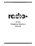
The TAS Series II is an advanced new Telephone Network Emulator from Spirent
Communications. The TAS Series II provides new high-end solutions for
development, testing, and evaluation of modems, fax machines, voice/data
terminals, transmission test sets, and other voice bandwidth data communications
devices.
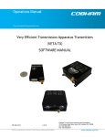
The TAS Series II offers complete bi-directional impairments simulation (Figure
1-1), The TAS Series II provides greatly enhanced echo simulation capabilities
and the ability to emulate virtually all worldwide central office signaling formats.
Figure 1-1. Series II Block Diagram
Because the TAS Series II is compatible with testing standards from EIA, CCITT,
ETSI, Bell Operating Companies, AT&T, Nippon Telephone and Telegraph, and
many other companies and industry organizations, test results have immediate
credibility. In addition, the TAS Series II is software-compatible with the older
TAS 1010 Channel Simulator, thereby protecting your prior investment in test
procedures and software.
TAS Series II works with the TAS Gemini Dual Terminal Emulator and TASKIT
software to provide completely automatic modem testing. TAS Series II test
results track with those obtained on the popular TAS 1010 and TAS 100 Series
1-2 TAS Series II Operations Manual
simulators, so the test results agree with the largest installed base of Telephone
Network Simulators in the world.
Introduction 1-3
1.2. TAS Series II Applications
1.2.1. Modem Evaluation and Test
Series II is an ideal tool for modem evaluation and test because it emulates an
end-to-end telephone network and provides a stable, controllable source of
telephone network impairments. Series II makes it easy to evaluate modem call
setup capabilities and impairment sensitivity. Combine the Series II with the
Gemini dual data analyzer and TASKIT software as shown in Figure 1-2 for a
complete modem evaluation workstation. For manufacturing test applications,
integrate the Series II and Gemini into a test fixture via IEEE-488 (GPIB) or RS232 control interfaces.
Figure 1-2. Series II Automatic Modem Testing Configuration
1-4 TAS Series II Operations Manual
Series II can also be used with the TAS Modem Test Switch as shown in Figure
1-3 to test several modems in succession, or to test modem inter-operability.
Figure 1-3. Series II/ 3508 Modem Test Switch Test Configuration
Introduction 1-5
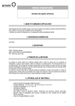
1.2.2. Fax Evaluation and Test
Series II provides a complete testbed for evaluating fax machine performance.
Simply connect a fax machine as shown in Figure 1-4, to each station set interface
and transmit a test document. With Series II, you can control transmission
impairments and central office parameters to thoroughly evaluate fax
performance.
Figure 1-4. Fax Testing Configuration
1-6 TAS Series II Operations Manual
1.2.3. Transmission Test Set Evaluation
Series II provides an accurate, stable source of transmission impairments making
it an ideal tool for evaluating the performance of Transmission Impairment
Measuring Sets (TIMS) as illustrated in Figure 1-5. Series II provides precise
control over all of the parameters that the TIMS measures, such as attenuation,
noise, phase jitter, amplitude jitter, etc. You can control the Series II and the
TIMS through the GPIB or the RS-232 to achieve completely automatic testing.
Figure 1-5. Configuration for Evaluating Transmission Impairments Measuring Set
Introduction 1-7
1.2.4. Communications Software Evaluation
Series II provides quick and easy evaluation of communications software
performance. To evaluate communications software, simply attach a computer and
modem to each station set interface as shown in Figure 1-6 and run the
communications software on the computer. Adjust Series II impairments and
central office parameters to completely evaluate software performance.
Figure 1-6. Configuration for Communications Software Evaluation
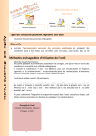
1.2.5. Credit Card Verification Terminal Evaluation
Series II allows you to evaluate the performance of data communications devices
that contain modems, such as a credit card verification terminal. To evaluate a
terminal, simply operate it in the normal manner, but substitute the Series II for
the real telephone network as illustrated in Figure 1-7. Adjust the Series II
impairments and central office parameters to thoroughly evaluate performance.
Figure 1-7. Configuration for Credit Card Terminal Evaluation
1-8 TAS Series II Operations Manual
1.3. TAS Series II Major Features
Figure 1-8. Telephone Network Emulator Architecture
1.3.1. Bi-directional Analog Impairments
Series II models provide bi-directional or unidirectional impairments. Bidirectional impairments most closely reflect the operation of real networks and
allow thorough evaluation of echo-canceling modems. Series II analog
impairments include:
•
Attenuation
•
White Noise
•
Gain Distortion
•
Group Delay Distortion
•
Non Linear Distortion
•
Phase Jitter
•
Frequency Offset
•
Amplitude Jitter
•
Gain Hits
•
Channel Interruptions
•
Phase Hits
•
Impulses
•
Single Frequency Interference
Introduction 1-9
Series II provides considerable impairments simulation flexibility including:
•
Selectable white noise source bandwidth
•
Selectable (expansive or compressive) nonlinear distortion modes
•
Selectable white noise pseudo-random sequence
•
TTL trigger inputs and sync outputs for impulses
1-10 TAS Series II Operations Manual
1.3.2. Bi-directional Digital Impairments
All Series II models are designed to accept the optional TAS PCM/ADPCM Links
(PAL) module. Bi-directional models have one PAL module in each direction of
transmission. Each PAL module emulates up to four PCM or ADPCM links and
supports the following testing features:
•
Mu-law and A-law PCM coding
•
64 kbps PCM and 40 kbps, 32 kbps, 24 kbps, and 16 kbps ADPCM coding
•
PCM robbed-bit signaling simulation
•
Random bit errors simulation
A bi-directional unit with the optional PAL modules may also accept the optional
Extended PCM/ADPCM Links module (EPAL). Typically on intercontinental
digital links non-standard ADPCM algorithms are employed. Many transatlantic
digital links use the ECI custom ADPCM while many transpacific digital links
utilize the OKI custom ADPCM. An EPAL module emulates up to two PCM or
non-standard ADPCM Links in both directions and supports the following
features:
•
64 kbps PCM and 32 kbps and 24 kbps custom ADPCM coding
•
User programmable Frame Slip emulation
1.3.3. Selectable Test Channel Configurations
The Series II supports four different Test Channel Configurations. Each test
channel configuration is defined by the impairments which are available, the order
in which the impairments are presented to the incoming signal, and the
background conditions generated by those impairments. The Test Channel
Configurations are:
•
EIA/CCITT Test Channel is based on EIA/TIA and CCITT specifications
and technical bulletins
•
ETSI Test Channel 1 is based on the NET 20 specifications and is
identical to the EIA test channel except for differences in frequency shift
and auxiliary echo
•
ETSI Test Channel 2/3 is based on the NET 20 specifications
•
Analog Bypass of the Test Channel. All impairments implemented
digitally are bypassed to avoid signal digitization. See table 2-3 for a list
of the impairments not supported.
Introduction 1-11
1.3.4. Advanced Echo Simulation Capability
Series II provides powerful echo simulation capabilities to facilitate thorough
analysis of echo-canceling modems. Series II provides near and far echo,
intermediate and listener echoes for each station. Far and intermediate echoes
experience all channel impairments and propagation delay. Near echo channels
provide direct electronic control of hybrid impedance for realistic, accurate
simulation.
1.3.5. Comprehensive Central Office Emulation
All Series II models provide extremely flexible automatic central office
emulation. The Series II Central Office Emulator provides the following key
features:
•
Emulates 2-wire switched, 2-wire non-switched, and 4-wire non-switched
operation
•
Emulates virtually all U.S. and international call progress signaling
formats. All call progress signaling tones may be user-defined
•
Dial pulse and DTMF detection
•
Constant current or constant voltage battery feed
•
Current source programmable up to 126 mA
•
Programmable battery feed voltage
•
Programmable battery feed resistance
•
Programmable ringing parameters: ring level, DC bias, ring frequency, and
ring polarity
•
Internal or external hybrid balance network
1.3.6. Extensive Signal Measurement and Monitoring Capabilities
Series II accurately measures signal levels at the input and output of each
transmission direction. Monitor/measure points are selectable via software
control.
1.3.7. Built-In Network Status Monitor
The Network Status Monitor presents the network configuration and call setup
status on the Series II front panel. Status information includes the type of network
being simulated (2-wire switched, 2-wire private line, 4-wire private line) and
switched network status (off-hook, dial tone, ringing, etc.). The Network Status
Monitor lets you quickly verify the call setup functions of modems, fax machines,
and other data communications equipment.
1-12 TAS Series II Operations Manual
1.3.8. Advanced System Architecture
Series II uses advanced digital signal processing (DSP) technology to pack the
signal processing power of the industry standard TAS 1010 Channel Simulator
onto a single circuit board. This results in unprecedented testing features,
accuracy, repeatability, and reliability.
The Series II also uses advanced new A/D and D/A conversion technology to
achieve much lower levels of background noise. This means that background
noise will not contaminate test results, even at receive signal levels as low as -50
dBm.
Introduction 1-13
1.4. Guided Tour
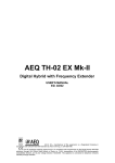
1.4.1. Front Panel Overview
Figure 1-9 shows the TAS Series II front panel. The panel contains a STATUS
and MODE display, and a pair of access connectors. Their functions are as
follows:
•
The STATUS display indicates the signaling status of the STATION A
and STATION B interfaces.
•
The MODE display indicates the telephone network interface line
configuration.
•
The STATION A and STATION B connectors (RJ-45) provide
transmission access to the TAS Series II telephone network emulator.
Figure 1-9. TAS Series II Front Panel
1-14 TAS Series II Operations Manual
1.4.2. Rear Panel Overview
Figure 1-10 on the following page shows the TAS Series II rear panel. The
following information provides a brief description of each rear panel feature.
•
The SCOPE AoB and SCOPE BoA BNC type connectors provide
selectable internal signal points for external monitoring.
•
The STATION A and STATION B connectors (RJ-45) provide
transmission access to the TAS Series II telephone network emulator in
parallel with the front panel RJ-45 connectors.
•
The External BoA terminal strip provides external access to the BoA
portion of the 4-wire path during 2-wire simulation.
•
The Balance Networks terminal strip allows a user-supplied balance
impedance for the 2- to 4-wire hybrids.
•
The rear panel has four BNC connectors: TRIGGER INPUT 1, SYNC
OUTPUT 1, TRIGGER INPUT 2, and SYNC OUTPUT 2. The TRIGGER
INPUTS provide for external impulse trigger generation. The SYNC
OUTPUTS can be used to synchronize other instruments to impulse
events.
•
The CONTROL (DTE) RS-232 port allows an external computer to
control the TAS Series II.
•
The AUX (DCE) RS-232 port is reserved for future use.
•
The CONTROL (IEEE-488) port allows an external GPIB controller to
control the TAS Series II.
•
The set of dip switches allows the selection of the remote control
communications protocol.
•
The MEMORY CARTRIDGE port accepts a TAS Series II program
memory cartridge.
•
The AC SWITCH/RECEPTACLE ASSEMBLY contains the AC ON/OFF
switch, the AC power connector, AC line voltage selection, and the fuse.
Introduction 1-15
Figure 1-10. TAS Series II Rear Panel
1-16 TAS Series II Operations Manual
1.5. Getting Started
1.5.1. Installation
To prepare the TAS Series II for operation, perform the following steps:
1. Unpack the TAS Series II shipping box. Check the contents of the box against
the list below.
Please make sure that all parts of your Series II Telephone Network Emulator
are present. Save the box and packing materials until you have completed the
system installation and initial check. If you must return any equipment to
TAS, please use the TAS packing material.
2. Check each item for physical damage. If any item appears damaged, please
contact your TAS customer service representative.
3. Check the AC voltage configuration. The current AC voltage setting is visible
through a plastic door at the right side of the AC receptacle. This setting
should have been factory-set per your locally available power system. Two
settings are available: 100 VAC or 240 VAC. The 100 VAC setting supports
100 to 125 VAC, and the 240 VAC setting supports 205 to 250 VAC.
Refer to the AC power information in the Detailed Rear Panel Control Jacks
and Ports portion in the Features Descriptions section of this manual, or
contact TAS for further instructions.
4. Verify that the Program Memory Cartridge is properly installed in the rear of
the TAS Series II.
5. Insert the AC power cord into the AC power connector to connect the TAS
Series II to an AC power receptacle.
6. Turn on the TAS Series II using the AC switch on the rear panel.
An automatic self-calibration and diagnostics procedure will be performed
immediately. During this procedure, the TAS Series II performs the following
functions:
1. Upon startup, the STATUS LEDS may flash up to six times, depending upon
the equipment arrangement, until all the STATUS LEDs are activated.
2. The STATUS LEDs then turn off sequentially from bottom to top, and then
turn on again, sequentially from bottom to top.
Introduction 1-17
3. At six points within the power-up operation, a tone is heard.
4. Calibrates internal signal processing elements.
5. Performs tests on internal circuitry.
6. Saves self-diagnostics results.
7. Successful completion of the power-up procedure is indicated when all the
STATUS LEDs turn off (after turning on per step 2 above) and only the 4
Wire Private LED is on.
NOTE: If the power-up procedure encounters a failure during its selftest/calibration operation, the sequential movement of LEDs will stop. If
necessary, obtain troubleshooting assistance from the TAS Customer Service
Department by calling 908-544-8700 or 908-544-8347 (fax).
1-18 TAS Series II Operations Manual
1.6. Quick Start-up Procedure
This section is an overview of each of the three Series 2 ⇔ Controller
communication configurations. An example of each of this configurations is as
follows:
•
RS232 ACK/NAK Control
•
RS232 CR/LF Control
•
Control with IEEE-488 Interface
Introduction 1-19
1.6.1. Software Control with the RS-232 ACK/NAK or CR/LF Interface
Connect the hardware as shown in Figure 1-11.
Figure 1-11. Control with the RS-232 Interface
Note: Control (DTE) port is located on the rear panel of the Series II
Set the system configuration remote protocol to "RS-232 ack/nak" or “RS-232
CR/LF” by setting the dip switch on the rear of the unit. From top to bottom, set
the dip switch as shown in Section 2.2.2.
Reset the Series II by switching "off" then "on" the rear panel AC power switch.
Configure the RS-232 interface on the controller as follows:
data bits: 7
parity: odd
stop bits: 1
bit rate: equal to rate set by Series II DIP switch
1-20 TAS Series II Operations Manual
1.6.2. Control with IEEE-488 Interface
Interconnect the hardware as shown in Figure 1-12.
Set the dip switch on the rear of unit as shown in Section 2.2.2. Reset the Series
II by switching "off" then "on" the rear panel AC power switch. Refer to section 3,
Programmer's Guide for additional information.
The TAS Series II GPIB protocol supports a bus communication architecture in
which the TAS Series II is one of the devices being controlled. The system
controller initiates all transactions.
1.6.3. In Case of Trouble
If you encounter a problem setting up or operating your TAS Series II system,
review the following paragraphs. If you are still unable to resolve the problem,
consult the technical staff at TAS. Before calling TAS, gather all information
relative to your problem, including the serial numbers on your equipment,
software version, and Program Memory Cartridge version. Please try to make
your problem description as concise and detailed as possible.
Here are some helpful hints.
•
If the Series II unit won't turn on, check the AC power connection and the
fuse.
•
If all front panel lights come on and stay on when the TAS Series II is
powered up and there is no other response, see if the Program Memory
Cartridge is securely installed in the rear of the channel emulator enclosure.
(Turn power off to perform this check.) Turn the unit off and then turn it on
again (cycle power).
Introduction 1-21
Figure 1-12. GPIB Software Control
Note: Control (IEEE-488) is located on the rear panel.
1-22 TAS Series II Operations Manual
1.7. Feature Release History
1.7.1. Version 2.31 Features
The following features have been added to the Series II version 2.31 cartridge.
•
Support for the Analog Bypass test channel topology
1.7.2. Version 2.20 Features
The following features have been added to the Series II version 2.20 cartridge.
•
Support for Cellular Audio Processing (CAP) module for the wireless
End-to-End solution
1.7.3. Version 2.10 Features
The following features have been added to the Series II version 2.10 cartridge.
•
Extended Caller ID including Caller Name Delivery (UCO)
•
RITT Gain/Delay filters
•
“True Voice” Gain/Delay filters
•
Extended Phase Jitter and Phase Hit Ranges
•
Support for Extended PCM/ADPCM Links module
1.7.4. Version 2.02 Features
The following features have been added to the Series II version 2.02 cartridge.
•
Support for additional bit rates for CFLF RS-232 remote control protocol
1.7.5. Version 2.00 Features
The following features have been added to the Series II version 2.00 cartridge.
•
CCITT Cable Gain Filters
•
White Noise Weighting Selection for Psophometric Standard
•
Series II Options Query Command (/AD,Qq/)
•
Extended Ringing Frequency Range (14 Hz to 120 Hz)
•
Call Progress Tones Frequency Range Extended Down to 100 Hz
Introduction 1-23
1.7.6. Version 1.30 Features
The following features have been added to the Series II version 1.30 cartridge.
•
Selectable Test Channel Configuration including:
EIA, CCITT and ETSI (NET 20) Configurations
•
Single Frequency Interference Sweep Mode
•
White Noise Weighting Selection for ETSI NET 20 Standard
•
Auxiliary Echo (Intermediate Talker or Listener Echo)
•
New TAS 1010-compatible IMD Algorithm
•
Enhanced EIA Gain/Delay Filters
•
New Gain/Delay Filters per ETSI NET 20 Standard
•
Parameter Readback (input values returned to user)
•
Attenuator Readback (current setting returned to user)
•
Loop Current Selectable in 2 mA Steps up to 126 mA
•
Selectable Loop Current Polarity
•
1 Volt Ringing Voltage Resolution
•
Selectable Ringing Polarity
•
Selectable DC Ringing Bias
•
Loopback Relay control
•
Program Resistor Relay control
•
Dialed Telephone Number Readback
1.7.7. Version 1.21 Features
The following features were included in the Series II version 1.21 cartridge.
•
A TAS 1010 Compatible Nonlinear Distortion Algorithm replaced the
proprietary Nonlinear Distortion Algorithm.
•
Bipolar Impulse noise duration and step size have been modified. The
step size of the duration parameter changed form 0.1 msec to 0.125 msec.
1-24 TAS Series II Operations Manual
1.7.8. Version 1.20 Features
The following features were included in the Series II version 1.20 cartridge.
•
The command set was expanded to include the internal/external hybrid
balance network command (i.e. the LC,B command was added).
•
The measurement command (MM,R) was modified to make the Series II
compatible with the TAS 1010 when the Series II is configured for
reversed impairment simulation.
•
Parameter ranges were extended for several commands:
Switching Delay (SW,M) range to 60,000 msec
Dial Tone Delay (SW,N) range to 60,000 msec
Signaling Cadence (SG,R) range to 60,000 msec
Busy Cadence (SG,B) to range to 60,000 msec
Bipolar Impulse Noise Interval to range 60,000 msec
•
A 40 Kbit ADPCM Quantization Rate was added to the PCM/ADPCM
option (see /PC,Q/ command).
1.7.9. Version 1.10 Features
The following features were included in the Series II version 1.10 cartridge.
•
Audio and visual indications were added to display the progress of the
Series II power-up sequence.
•
The AGC operation now includes muting the speaker during the AGC
operation and automatic reconfiguration of the signal path to the pre-AGC
setting upon completion of the operation.
Introduction 1-25
1.8. Series II Options
1.8.1. Universal Central Office (UCO) Emulation
Universal Central Office (UCO) Emulation is an exciting new feature that
significantly expands the Central Office (Exchange) emulation capabilities of the
TAS Series II. This important feature allows the Series II to emulate practically
any exchange signaling format that exists on public switched telephone networks
worldwide as well those found in Private Branch Exchanges (PBXs)
environments. UCO provides the user with the capability to test the call setup
functionality of his equipment for a universe of domestic and international
conditions.
1.8.2. Summary of Major UCO Features
Series II UCO provides the industry's most extensive and flexible central office
(exchange) emulation features. The major features include:
Emulates 2 independently controlled central offices (exchanges), each with more
than 100 user definable parameters.
Emulation of virtually all U.S. and international call progress signaling tones
including:
•
Dial Tone
•
Second Dial Tone
•
Recall Dial Tone
•
International Dial Tone
•
Ringing Tone (Ringback)
•
Busy Tone
•
Receiver Off Hook Tone
•
Congestion (Reorder, Fast Busy, Network Busy)
•
Special Information Tone
•
Warning Tone
•
Number Unobtainable Tone
•
Call Waiting Tone
•
Recording Tone
•
Executive Override Tone
•
Intercept Tone
1-26 TAS Series II Operations Manual
•
Pay Tone
•
Function Acknowledgment Tone
•
Confirmation Tone
•
Route Tone (Call in Progress)
•
Prompt Tone (Credit Card Bong Tone)
Provides more than 240 predefined call progress signaling tones.
Provides predefined call setup sequences for more than 30 different countries.
Provides a powerful arbitrary waveform synthesizer with an easy to use script
language that allows the user to build virtually any custom signaling tone.
Emulates Caller ID (Call Number Delivery), Call Waiting and automatic credit
card call setup sequences. (additionally Caller Name Delivery in v2.10 and higher)
Supports user defined call setup sequences. Allows up to a 100 digit dialing
sequence.
Emulates reverse polarity signaling.
Provides extensive dialing analysis for both DTMF and dial pulsing.
1.8.3. PCM/ADPCM Module
The PCM/ADPCM Links (PAL) module provides the means to test modem
performance over various simulated digital transmission systems. The PAL
module can be positioned in the signal path to appear either before satellite delay
or after the noise summer. With a PAL module, it is possible to perform the
following functions:
•
Simulate up to 4 tandem, digitally coded transmission links
•
Specify each link as mu-law or A-law with 64 kbps PCM, 40 kbps
ADPCM, 32 kbps ADPCM, 24 kbps ADPCM, or 16 kbps ADPCM
•
Inject random bit errors on the PCM or ADPCM bit stream of one of the 4
transmission links
•
Insert PCM robbed-bit signaling on one of the 4 transmission links
Introduction 1-27
1.8.4. Extended PCM/ADPCM Module
The Extended PCM/ADPCM Links (EPAL) module provides the means to test
modem performance over various simulated digital transmission systems currently
found over international links. The EPAL module (also called the Digital
Channel) can be positioned in the signal path to appear either before satellite delay
or after the noise summer. With an EPAL module, it is possible to perform the
following functions:
•
Simulate up to 2 tandem, digitally coded transmission links
•
Specify each link as mu-law or A-law with 64 kbps PCM, 32 kbps ECI or
OKI ADPCM, or 24 kbps OKI ADPCM
•
Inject random frame slip errors on the PCM or ADPCM bit streams of one
of the 2 transmission links in each direction
1.8.5. Cellular Audio Processor (CAP) Module
The TAS Series II Cellular Audio Processor (CAP) Module emulates the
companding, pre-emphasis/de-emphasis, and limiting characteristics associated
with end-to-end cellular network connections. These VF (Voice Frequency )
characteristics are defined by EIA/IS-19-B, and 20A as well as EIA/TIA-553, and
EIA/TIA/IS-55 cellular standards. TAS Series II CAP allows the TAS Series II
Telephone Network Emulator to provide the user with a cost effective and
convenient means to test the performance of cellular modems and other VF
(Voice Frequency) devices that must operate over analog cellular networks.
Multiple test topologies are supported by the Series II CAP to allow the TAS
Series II to address a variety of test applications including:
Complete End-to-End (VF to RF to VF) Cellular Test Application
In this application the TAS Series II with a CAP module in addition to a base
station emulator (TAS 6600) and RF channel emulator (TAS 4500) are used to
test the effects of both the VF and RF characteristics of a cellular communications
channel. This application requires the Series II CAP to be configured in the “GT
Cellular” topology.
Stand Alone VF Only Test Application
In this application the TAS Series II with the CAP module are used to test the
effects of only the VF characteristics of a cellular communications channel. This
application requires the Series II CAP to be configured in the “Tandem” topology.
1-28 TAS Series II Operations Manual
System Requirements
The TAS Series II Telephone Network Emulator requires the following resources
to provide the cellular audio processor feature:
•
TASKIT/Series II for Windows Software Version 1.30 or higher
•
TAS Series II Program Memory Cartridge Version 2.20 or higher
•
TAS Series II Cellular Audio Processor Hardware Module Version 1.0 or
higher
1.8.6. Channel Access Module
The Series II optional Channel Access Module (CAM) provides the means to
obtain 4-wire access to the transmit and receive ports of the AoB and BoA
transmission channels when the Series II is configured for 2-wire operation. With
the CAM, it is possible to perform the following functions:
•
Cascade external transmission or simulation equipment with the internal
transmission channels of the Series II.
•
Access all four ports of the Series II 2-wire to 4-wire hybrids including the
transmit and receive 4-wire ports.
•
Simulate a 4-wire switched network configuration.
1.8.7. Line Interface Adaptor
The TAS Line Interface Adaptor (LIA) is a general purpose breakout box for
telecommunications applications. The LIA provides several alternative connection
types to the standard RJ-45 modular jack. These alternatives include banana jacks,
2-wire RJ-11 jack, 4-wire RJ-11 jack, and WECO 310 type connector. In addition
to the different connector types, the LIA also provides a switchable 6.1 dB
attenuator pad on pins 4 and 5 of the network RJ-45 connector.
Introduction 1-29
1.9. Companion Products
1.9.1. TAS Gemini Dual Terminal Emulator
The TAS Gemini Dual Terminal Emulator is a data communications
tester/analyzer that is specifically designed for end-to-end testing of modern data
communications equipment by including two data analyzers in one compact
package. Gemini provides a host of digital tests such as bit error rate, throughput,
polling, calls test, and message analysis. Gemini displays test setup and test results
information on its 80 character main display. Gemini maintains this information
for each of its two independent data analyzers. In addition to performing error rate
and throughput tests, Gemini allows you to enter and send command strings to
auto-dial modems. This completely eliminates the need for a separate terminal or
protocol analyzer.
Figure 1-13. VSLE Application
1-30 TAS Series II Operations Manual
1.9.2. TAS 3508A Modem Test Switch
The TAS 3508A Modem Test Switch (MTS) is a switching unit that allows one of
nine modems to be switched to a common port under IEEE-488, RS-232, or front
panel control. The MTS is designed to simplify and streamline automatic testing
of modems, DDS sets, ISDN terminal adaptors, and other data communications
equipment.
A simple cascade arrangement makes it possible for one "master" switch to
control up to 31 additional switches, allowing one of 256 modems to be switched
to a common port. The MTS can be easily integrated into existing automatic test
arrangements with other TAS components and TASKIT software to provide fully
integrated test systems.
1.9.3. TAS 240 Voiceband Subscriber Loop Emulator
The TAS 240 Voiceband Subscriber Loop Emulator (VSLE) provides convenient,
accurate simulation of voiceband subscriber loop characteristics. The VSLE is
designed for complete compatibility with emerging and proposed specifications
from the Electronic Industries Association (EIA), the European
Telecommunications Standards Institute (ETSI), and the CCITT.
The VSLE can be used in conjunction with all TAS Telephone Network
Emulators and TASKIT software to facilitate complete evaluation of advanced
high-speed modems as illustrated in Figure 1-13. It emulates four complete
subscriber loops. These four loops are organized as a "main" loop and a "tracking"
loop at each side of the network. The main loop emulates the telephone subscriber
loop and the tracking loop balances the hybrid in the telephone network emulator.
2.0. FEATURES DESCRIPTION
2.1. Overview
The TAS Series II Telephone Network Emulator is comprised of four major
functional components, these are:
The User Interface
This includes all connectors, indicators, input/output jacks, and user controls on
both the front and rear panels of the Series II, as well the remote control protocols.
Transmission Channel Emulation
This component includes the circuitry which generates all of the impairments of
the Series II. These impairments are divided into digital impairments, analog
impairments, and echo. The transmission channel also contains both the input and
output level control sections. A major feature of the transmission channel is
programmable test channel configurations, this allows the impairment profile (the
impairments which are present and their order) to be selected. The Series II
model 1200 supports channel configurations for the Electronic Industries
Association (EIA), European Telecommunications Standards Institute (ETSI), and
the International Telegraph and Telephone Consultative Committee (CCITT).
Measure/Monitoring
This includes the level and frequency measurement, audio output, and scope jack
outputs.
Central Office Emulation
This component includes all of the simulation required to emulate both switched
and private line telephone networks. The Series II supports full programmability
of exchange configuration features, loop signaling, call progress tones, and dialing
analysis. Both pulse dialing and DTMF (Dial Tone Multi-Frequency) are fully
supported.
Each of these sections is fully explained in this section of the manual.
2-2 TAS Series II Operations Manual
2.2. User/Operational Interface
The user interface is presented on the front and rear panels, and by the remote
control protocols. The front panel contains status LEDs and RJ-45 modular jacks
for access to the network. The rear panel contains the power entry module,
memory cartridge, fan, control interface (connectors and a switch), modular jacks
(paralleled with those on the front panel), and several additional connectors.
2.2.1. Front Panel Displays and Ports
On the right hand side of the front of the Series II is a sub-panel which contains
LEDs and the station A and B modular jack receptacles (see Figure 2-1). The
LEDs are used to indicate the network mode and station interface status, in
addition these LEDs are used to indicate any diagnostic failure encountered during
a system power-up, or a "soft-reset".
Figure 2-1. Front Panel Displays and Ports
Features Description 2-3
Network Mode LEDs
The network may be programmed to operate in one of three modes. The "MODE"
LED which corresponds to the current state will be lit. The network mode LEDs
and their meanings are:
SWITCHED 2W - Indicates that the telephone network emulation is configured
for 2-wire switched or 2-wire auto-switched mode.
PRIVATE 2W - Indicates that the telephone network interface emulation is
configured for 2-wire private line mode.
PRIVATE 4W - Indicates that the telephone network interface emulation is
configured for 4-wire private line mode.
Station Interface Status LEDs
The status LEDs are used to indicate the status of the station interface when the
mode is 2-wire switched or 2-wire auto-switched. The status indicates the state of
the signaling at both stations A and B. The status of the station interface is
defined by the following:
OFF HOOK: indicates that station A and/or B is off hook and that loop current is
flowing.
DIAL TONE: indicates that station A and/or B is receiving dial tone.
RING BACK: indicates that station A or B is receiving a ring back tone.
RINGING: indicates that station A or B is receiving ringing voltage.
CONNECTED: indicates that the call set-up sequence has been successfully
completed and that stations A and B are connected.
BUSY: indicates that an unsuccessful attempt was made at station A and/or B to
ring the opposite station. This can happen when the dialed station is off hook, or
because the number dialed at one station is different from the other station's
telephone number.
NOTE: At any given time one station may have more than one LED lit. For
example once one telephone (or modem) goes off hook both the "OFF HOOK"
and "DIAL TONE" LEDs will both be lit for that station.
2-4 TAS Series II Operations Manual
Diagnostic Failure Indication
When powering up, or after sending a "soft" reset command, the front panel
indicators go through a start-up sequence as described in the INTRODUCTION
section of this manual. If a failure occurs during this start up, the state of the
indicators are frozen at that point. If no problems are encountered, the indicators
are extinguished except for the Private 4W indicator (default configuration).
Station A and B Modular Jacks
Station A and station B modular telephone jacks are RJ-45 type receptacles, they
are located in the lower right-hand corner of the front panel. These station set
interfaces conform to all mechanical/functional characteristics specified in the
EIA TR30.3 Telecommunications Systems Bulletin No. 18. The pin
configurations for 2-wire and 4-wire station set interfaces are shown in Figure 2-2
and Figure 2-3.
Features Description 2-5
Figure 2-2. Station Interface in 2-Wire Configuration
2-6 TAS Series II Operations Manual
Figure 2-3. Station Interface in 4-Wire Configuration
Features Description 2-7
2.2.2. Rear Panel Controls, Jacks and Ports
The rear panel contains a remote control interface (consisting of a switch and
three connectors), the AC power entry module and switch, a Memory Cartridge
receptacle, a fan, two scope monitor BNC connectors, two modular RJ-45 type
receptacles, two terminal strips which present internal points to the user, and two
pairs of a trigger input and a sync output connector. The detailed functionality of
each of these is explained below.
Figure 2-4. Remote Control Interfaces
Remote Control Interface
The remote control interface on the rear panel consists of the three connectors and
one DIP switch residing directly beneath the fan assembly (see Figure 2-4). The
connectors are labeled "AUX (DCE)", "CONTROL (DTE)", and "CONTROL
(IEEE-488)", and the switch is labeled S0-S5.
2-8 TAS Series II Operations Manual
RS-232C CONTROL (DTE) Port
The CONTROL (DTE) port is a 25 pin D-sub connector which supports RS232C. The control port is wired as a Data Transmission Equipment (DTE). All
RS-232C remote control of the Series II must be done via this port. An RS-232C
terminal or a PC (IBM compatible) can control the TAS Series II through this port
via a null modem cable (a sample null modem is provided with any Series II).
Two protocols are supported in RS-232 control mode, ACK/NAK
(ACKnowledge/Negative AcKnowledge, and CR/LF (Carriage Return/Line Feed).
Both of these protocols are explained in full detail in the PROGRAMMER'S
GUIDE section of this manual.
RS-232C AUX (DCE) Port
The AUX (DCE) port (auxiliary) is a 25 pin D-sub connector which supports RS232C. The auxiliary port is wired as a Data Communications Equipment (DCE).
The auxiliary port is reserved for future use.
CONTROL (IEEE-488) Port
The CONTROL (IEEE-488) port is a 24 pin IEEE-488 receptacle which supports
the IEEE-488 (GPIB) protocol. This port must be connected to an IEEE-488
controller to control the Series II via IEEE-488. This connection may be either
direct or via a multi-point bus which contains other IEEE-488 controlled
equipment.
The IEEE-488 controller may be a generic PC with an embedded IEEE-488
control card installed, a IEEE-488 computer, an RS-232 to IEEE-488 converter, or
some other IEEE-488 controller. For an installation which includes a TAS
Gemini and TASKIT software the Gemini serves as the IEEE-488 controller.
Features Description 2-9
Configuration DIP Switch
Once a control mode has been determined, the Series II DIP switch on the rear
panel must be programmed to expect that protocol. The switches are used to
indicate not only the protocol, but all other information which is programmable.
The information below details the switch settings:
S5
0
S4
1
S3
b1
S2
a2
S1
a1
S0
a0
CONTROL MODE
RS-232 ACK/NAK
b1 = 0 → 4800 bps
b1 = 1 → 9600 bps
0
0
0
0
b2
b1
a2,a1,a0 = Address (binary weighted
with a2 as MSB), valid range from 0-7.
RS-232 CR/LF
b2
0
0
1
1
1
a4
a3
a2
a1
a0
b1
Bit rate
0
1200 bps
1
2400 bps
0
4800 bps
1
9600 bps
IEEE-488
a4 thru a0 = Address (binary weighted with
a4 as MSB), valid range from 0 to30.
Table 2-1. DIP Switch Configurations
Figure 2-5. Examples of Configuration DIP Switch Settings
Figure 2-5 illustrates typical configuration switch settings, including an example
for each one of the three transmission layer protocols.
2-10 TAS Series II Operations Manual
The TAS Series II reads the configuration switches during system initialization.
To enforce a change in the dip switch settings, you must cycle the AC power after
the switch settings have been changed.
RS-232C ACK/NAK Protocol Configuration Switch Setup
When the control mode is RS-232 ACK/NAK the user must program two
additional parameters, the bit rate and the address.
The baud rate of the Series II for RS-232 ACK/NAK is controlled by switch S3
(b1). The switch S3 (b1) controls the port bit rate as follows:
0
1
4800 bps
9600 bps
The address of the Series II for RS-232 ACK/NAK is controlled by switches S2
(a2), S1 (a1), and S0 (a0).
a2, a1, a0 = the station address in binary (0-7)
For ACK/NAK protocol the Series II expects the data format to be 7
bits/character, odd parity, and 1 stop bit.
The ACK/NAK protocol should only be used if the environment may cause errors
on the transmission link (ACK/NAK protocol has built-in error detection
capabilities), or multiple units are to be controlled from one controller. The
multipoint capability of the ACK/NAK protocol requires the use of a port sharing
device (contact TAS customer service for more information). This feature will
allow for control of up to eight Series IIs (each with its own unique
ACK/NAKaddress) from a single RS-232 controller port.
RS-232C CR/LF Protocol Configuration Switch Setup
When the control mode is RS-232 CR/LF there is one additional parameter to set,
the bit rate. The Series II expects the data format to be 7 bits/character, odd parity,
and 1 stop bit. The bit rate is selected via the switches S1 (b2), and S0 (b1), the
selections are:
b2
0
0
1
1
b1
0
1
0
1
Rate
1200 bps
2400 bps
4800 bps
9600 bps
Features Description 2-11
IEEE-488 (GPIB) Protocol Configuration Switch Setup
When the control mode is IEEE-488 the user must program one additional
parameter, the bus address of the Series II.
The address of the Series II for IEEE-488 is controlled by switches S4 (a4) to S0
(a0).
a4, a3, a2, a1, a0 = the station address in binary 0 - 30 (00000 - 11110)
AC Power Switch
The AC power switch is located at the lower left of the rear panel (as viewed from
the rear of the unit). Push this switch to turn the AC power on or off.
AC Power Receptacle
The AC power receptacle is located on the left rear portion of the rear panel. This
receptacle also contains the fuse for the unit. The TAS Series II unit is factory-set
for a customer's local power. If it becomes necessary to change that setting, the
proper procedure for performing the operation is described below:
1. Remove the power cord and move the plastic slide to the left to reveal the fuse
and power selector board (present setting of 100 or 240 should be visible).
2. Pull out the power selector board and then reinsert it for the desired setting
(That setting should be facing up and readable after insertion).
Software Cartridge Port
A software cartridge port is located at the upper left of the rear panel. The TAS
Series II Program Memory Cartridge, which contains the TAS Series II control
program, must be inserted into this port before power is turned on.
CAUTION: Do not install or remove the Program Memory Cartridge
while the power is on.
Signal Input/Output Connectors
There are several connectors located on the rear on the Series II on the right hand
side of the panel (see Figure 2-6). The functions of each of these connectors is
described below.
2-12 TAS Series II Operations Manual
Figure 2-6. Rear Panel Signal I/O Connectors
Trigger Input and Sync Output Jacks
Two pairs of trigger and sync jacks are provided on the rear panel. These jacks
are designated as TRIGGER INPUT 1, SYNC OUTPUT 1, TRIGGER INPUT 2,
and SYNC OUTPUT 2. TRIGGER INPUT 1 and SYNC OUTPUT 1 are
dedicated to Impairments Generator 1 (A to B), and TRIGGER INPUT 2 and
SYNC OUTPUT 2 are dedicated to Impairments Generator 2 (B to A).
TRIGGER INPUT 1 and 2 can be supplied with TTL inputs which may be used as
a trigger for the TAS Series II internal impulse noise generator. The TAS Series II
only uses these inputs as the trigger when the external trigger or external single
shot trigger mode is selected. If used, the impulse is triggered on the falling edge
of the input signal. When using external triggering, the TAS Series II allows for a
user programmed trigger delay interval.
TTL pulses are provided on the SYNC OUTPUTS by the internal impulse
generators. These outputs are provided independently of the selected trigger
mode. The output signals are synchronized to the impulse events occurring on the
line, and they can be used to synchronize other instruments (i.e., storage scope) to
the impulses.
Features Description 2-13
Station A and B Modular Jacks
Station A and station B modular telephone jacks are located in the middle of the
right-hand side of the rear panel. These jacks are connected in parallel with the
front panel jacks and are configured identically. The pin out for these connectors
is shown in figures 2-2 and 2-3.
External Bo
oA (B to A Path Breakout Terminal Strip)
The external B to A terminal strip is located near the bottom of the right side of
the rear panel. By enabling the "external reverse channel" command (see the
"/LC,Ee/" command in PROGRAMMER'S GUIDE section of this manual), the
signals in the B to A direction through the transmission channel are presented on
this terminal strip. The signal path through the Series II is completely broken to
allow the insertion of additional impairments to the signal. The output of the
Series II B to A transmission channel is provided on the pins labeled "T2" and
"R2", and the input signal should be provided back into the Series II on the pins
labeled "T1" and "R1". The nominal signal level at the output pins will be the
output level currently set for the B to A direction, the level of the input signal
returned to the Series II will determine the output level of the Series II at the front
(and rear) station B modular jack. See "B to A Channel Access" in the Central
Office portion of this section.
Balance Networks Terminal Strip
The balance networks terminal strip is located on the right side of the rear panel.
This terminal strip provides the means to substitute other hybrid balancing
impedances for those internal to the TAS Series II. Nominally the Series II
provides a 604 ohm balance impedance. See "Hybrid Balance" in the Central
Office portion of this section.
Scope Ao
oB and Scope Bo
oA Connectors
Two BNC ports are provided on the rear panel for monitoring signals which
normally may not be presented to the user. Designated SCOPE AoB and SCOPE
BoA, they are located near the top of the right side of the rear panel. The TAS
Series II can be directed to select and provide internal signals at this BNC-type
jack for external monitoring. The following signals (see Figures 2-2 and 2-3) may
be selected:
2-14 TAS Series II Operations Manual
AoB SCOPE:
•
a xmit (A0): transmit level of the equipment connected to station A. This
signal is monitored on the four wire side of the hybrid.
•
b rcv 4w (B1): signal level received at the station B 4-wire point.
•
b rcv 2w (B2): signal level received at the station B 2-wire point. This signal
is monitored on the four wire side of the hybrid.
BoA SCOPE:
•
b xmit (B0): transmit level of the equipment connected to station B. This
signal is monitored on the four wire side of the hybrid.
•
a rcv 4w (A1): signal level received at the station A 4-wire point.
•
a rcv 2w (A2): signal level received at the station A 2-wire point. This signal
is monitored on the four wire side of the hybrid.
An audible representation of the selected AoB or BoA signal is available on the
internal speaker.
Features Description 2-15
2.2.3. Remote Control Features
The TAS Series II may be controlled remotely by either RS-232, or IEEE-488.
Two protocols are available under RS-232 control, ACK/NAK
(ACKnowledge/Negative ACKnowledge) for use in situations where error
detection is required such as control via modems, and CR/LF for use where error
detection is not required. ACK/NAK also supports control of multiple simulators
from the same master communications port. The IEEE-488 protocol is only used
when controlled by a IEEE-488 controller.
The command structure used to control the Series II is independent of the control
mode or protocol. A typical command for the Series II would contain a function
(group) id followed by one or more parameter ids with associated data.
There are a few special commands and control features which are described here.
The Series II supports several test channel configurations which differ in the
impairments which are available to the user, and the ordering of the impairments.
The user may program the parameters for all impairments at any time regardless
of whether the impairment is currently supported. These parameters will take
effect once the channel configuration is changed to one which includes that
impairment.
The Series II supports several "software straps" which set some operational
characteristics of the Series II (refer to the command summary, AD commands for
more details). Among these are the selection of IEEE impulses or bipolar
impulses. These straps are reset to the factory default by the "soft reset" command
and at power-up.
Finally the Series II (PMC version 1.3 and above) supports "parameter readback"
of any user programmable parameter. This feature allows the user to poll the
Series II to determine the setting of any parameter.
Refer to the command summary for detailed information on the protocols,
command structure, and specific commands.
2-16 TAS Series II Operations Manual
2.3. Channel Access Module (Optional)
System requirements include the following:
•
TASKIT Software: Version 4.50 or higher
•
TASKIT for Windows Software: Version 1.0 or higher
•
Series II Program Memory Cartridge: Version 1.30 or higher
•
Network Interface Module (NIM) 2B: Version 1.30 or higher
2.3.1. CAM Module
The Series II optional Channel Access Module (CAM) provides the means to
obtain 4-wire access to the transmit and receive ports of the AoB and BoA
transmission channels when the Series II is configured for 2-wire operation. With
the CAM it is possible to perform the following functions:
1. Cascade external transmission or simulation equipment with the internal
transmission channels of the Series II.
2. Access all four ports of the Series II 2-wire to 4-wire hybrids including the
transmit and receive 4-wire ports.
3. Simulate a 4-wire switched network configuration.
A 600 ohm differential input interface along with a 600 ohm balanced output
interface is provide at the 4-wire transmit port and at the receive port of each
hybrid. These interfaces are available on the left side of the Series II rear panel as
illustrated in Figure 2-7. Two 8 pin modular jacks labeled CAM A and B provide
access to the station A and station B ports respectively. The signals available on
modular jack A are listed in the second column of Table 2-2 and the signals
available on modular jack B are in the third column.
Features Description 2-17
Figure 2-7. Rear Panel Channel Access Module Connectors
Pin #
1
2
3
4
5
6
7
8
CAM A Modular Jack
Station A receive output ring
conductor
Station A receive output tip
conductor
Station A receive input tip
conductor
Station A transmit input ring
conductor
Station A transmit input tip
conductor
Station A receive input ring
conductor
Station A transmit output tip
conductor
Station A transmit output ring
conductor
CAM B modular Jack
Station B receive output ring
conductor
Station B receive output tip
conductor
Station B receive input tip
conductor
Station B transmit input ring
conductor
Station B transmit input tip
conductor
Station B receive input ring
conductor
Station B transmit output tip
conductor
Station B transmit output ring
conductor
Table 2-2. Channel Access Module Interface Summary
2-18 TAS Series II Operations Manual
Figure 2-8 provides a high level view of the location of the optional CAM
interfaces, in addition to the standard B to A access interface.
Figure 2-8. Optional CAM Interfaces
Features Description 2-19
Figure 2-9 shows the location of the CAM A signals and Figure 2-10 shows the
CAM B signals. To use one of the access interfaces provided by the CAM, the
interface must be enabled with the LC,A command. To insert an external device
in series with the internal transmission channels of the Series II, the CAM
interface signals designated as outputs should be connected to the input of the
external device, and the CAM signals designated as inputs connected to the output
of the external device. The use of Line Interface Adapters is recommended to
facilitate easy access to the modular jack pins for the relevant tip and ring
combinations.
Figure 2-9. Station A CAM Interfaces
2-20 TAS Series II Operations Manual
Figure 2-10. Station B CAM Interfaces
A 4-wire switched network configuration may be created by enabling both the
station A and station B transmit CAM interfaces. The transmit (output) tip/ring
signal pair of the 4-wire switched communications equipment (telephone or
modem) at station A should be connected to pins 5 and 4 of CAM A jack on the
Series II rear panel ( - use of a Line Interface Adapter is recommended for
simplified access to pins). Pins 5 and 4 of the Series II station A modular jack
should connect to the receive (input) tip/ring pair of the station A 4-wire
equipment. Likewise, the transmit (output) tip/ring signal pair of the 4-wire
switched communications equipment at station B should be connected to pins 5
and 4 of CAM B jack on the Series II rear panel. Pins 5 and 4 of the Series II
station B modular jack should connect to the receive (input) tip/ring pair of the
station B 4-wire equipment. This setup will supply loop current for hook status
detection, ringing and call progress tones to the receive pair (pins 5 and 4 of the
modular jack) only of the 4-wire communications device. However, the device
must transmit its DTMF (touch-tone) dialing information on the transmit pair.
Features Description 2-21
2.4. Transmission Channel (Trunk) Simulator
A high level block diagram of the transmission channel simulator of the Series II
in shown in Figure 2-11. The transmission channel consists of an input level
control, an optional impairments generator (including echo), and an output level
control. A single transmission channel processes signals in only one direction at a
time. All TAS Series II units are equipped with two transmission channel
simulators and an impairment generator in each channel.
Figure 2-11. Transmission Channel Simulator Block Diagram
The impairment generator is capable of simulating a wide variety of voiceband
impairments. These impairments are divided into analog, digital, and echo.
Analog impairments are those which affect the signal during transmission on
analog facilities such as noise and frequency shift. Digital impairments are those
which are experienced due to transmission on digital facilities. The digital
impairments of the Series II are PCM/ADPCM, bit errors, frame slips, and robbed
bit signaling. Echo results from the impedance mismatches which occur at analog
interfaces.
A major feature of the Series II is the ability of the impairment generator to
simulate many different impairment configurations (or topologies) without any
hardware changes. These different impairment configurations arise from the
many organizations around the world independently specifying test conditions for
modems and other voice band transmission devices. These organizations include
(but are not limited to) the EIA, ETSI, and other independent PTTs. The
configurations provided by the Series II are discussed below in detail.
Configuration changes are implemented by issuing a command to the Series II.
2-22 TAS Series II Operations Manual
2.4.1. Test Channel Configuration Programming
The test channel configuration of the Series II is defined by the impairments
which are available, the order in which the impairments are presented to the
incoming signal, and the background conditions generated by those impairments.
The Series II supports three different configurations, one representing the network
defined by the EIA and CCITT (designated EIA), a second representing the
network defined by the ETSI as test line 1 (ETSI-1), and the third configuration
represents the ETSI test line 2 (ETSI-2). See Figures 2-12 through 2-15 for
detailed diagrams of these configurations.
Features Description 2-23
Figure 2-12. TAS Series II EIA/CCITT Test Configuration
2-24 TAS Series II Operations Manual
Figure 2-13. TAS Series II ETSI-1 Test Configuration
Features Description 2-25
Figure 2-14. TAS Series II ETSI-2 Test Configuration
2-26 TAS Series II Operations Manual
Figure 2-15. ETSI NET 20 Test Bench
Table 2-3 details the impairments which are present in each of the three
configurations. Note that configuration ETSI-2 has limited the number of
impairments present in the simulation. This is due in part to the requirements of
the ETSI NET 20 regarding the delay experienced from end to end. Each of the
impairments will be discussed fully in proceeding sections.
Features Description 2-27
Impairment
Amplitude Jitter
EIA/CCITT
Yes
ETSI-1
Yes
ETSI-2
No
Analog Bypass
No
Frequency Shift
Yes
Yes
No
No
Gain/Delay Distortion
Yes
Yes
No
No
Gain Hits
Yes
Yes
No
No
Impulse Noise (IEEE)
Yes
Yes
Yes
No
Impulse Noise (Bipolar)
Yes
Yes
Yes
No
Interruptions 1
Yes
Yes
No
No
Interruptions 2
No
No
Yes
No
Non-linear Distortion (IMD)
Yes
Yes
Yes
No
Phase Hits
Yes
Yes
No
No
Phase Jitter
Yes
Yes
No
No
Single Frequency Interface (SFI)
Yes
Yes
Yes
No
White Noise
Yes
Yes
Yes
Yes
Auxiliary Echo 1
(Listener or Intermediate)
Yes
Yes
No
No
Auxiliary Echo 2
(Listener of Intermediate)
No
No
Yes
No
Satellite Delay 1
Yes
Yes
No
No
Satellite Delay 2
No
No
Yes
No
Echo - Near
Yes
Yes
Yes
Yes
Echo - Far
Yes
Yes
Yes
Yes
PCM/ADPCM (if present)
Yes
Yes
Yes
Yes
Table 2-3. Impairment Channel Configuration Definition
The Series II has two Interruption, Satellite Delay, and Auxiliary Echo generators.
However, only one is available in any configuration. The programming for each
pair of impairments is completely independent (i.e. the Satellite Delay module 1
parameters are programmed independently from the Satellite Delay module 2
parameters). The parameters for any impairment generator may be programmed
even though that module may not be present in the current configuration (i.e.
Satellite Delay 2 parameters may be programmed while current configuration is
EIA). Both IEEE impulse noise and Bipolar impulse noise are shown on the table
above, however only one is available at any given time.
2-28 TAS Series II Operations Manual
EIA Test Channel
The EIA/CCITT test channel configuration is based on the following
specifications:
•
EIA/TIA-496-A
•
EIA TR30.3 "Proposed Test Channels for V.32 and Asymmetrical Modems"
•
EIA/TIA Technical Bulletin (PN 2825)
•
CCITT Study Group XVII TD-237
ETSI Test Channel 1
The ETSI test channel 1 configuration is identical to the EIA test channel with
only two differences:
•
Frequency shift module moved to first module after input control
•
The residual propagation delay changes from 12.9 msec to 15.8 msec
The ETSI test channel 1 is based on the NET 20 specifications. Note that the
actual implementation of this test channel is a super-set of the configuration in the
ETSI document. The Series II implementation however becomes identical to the
ETSI configuration when the following impairments are turned off (default state):
A to B Channel:
•
Intermodulation Distortion (IMD)
•
Amplitude Jitter
•
Single Frequency Interference
B to A Channel:
•
All impairments except:
Frequency Shift
Satellite Delay
Features Description 2-29
ETSI Test Channel 2/3
The ETSI test channel 2 is based on the NET 20 specifications. Note that the
actual implementation of this test channel is a super-set of the configuration in the
ETSI document. The Series II implementation however becomes identical to the
ETSI configuration when the following impairments are turned off (default state):
A to B Channel:
•
Auxiliary Echo
B to A Channel:
•
All impairments except Satellite Delay
The ETSI test channel 3 configuration is identical to test channel 2 configuration,
however the following impairments must be turned off (or not used during test):
•
Near Echo
•
Far Echo
•
Interruptions
•
Single Frequency Interference (SFI)
•
Impulse Noise
•
Random Noise
See application note, "Simulation of ETSI NET 20 Test Bench" for more
information.
2.4.2. I/O Configurations
The Series II allows two choices for the source of the input signal to the
transmission channel simulator, external and internal. The external selection
allows the user to input a signal via either the front panel or rear panel jacks. The
internal selection uses the Series II internal tone generator as the input signal.
Tone Generator
The Series II provides two independent internal tone generators. One generator is
dedicated to the A to B transmission channel and the other to the B to A channel.
The user may set the frequency of the internal tone sources in 1 Hz steps from 200
Hz to 3400 Hz. The level of the internal tone is preset to 0.0 dBm and is fixed.
When internal signal source is selected in the A to B direction of the Series II, the
tone source replaces the external user supplied signal. The internal tone source is
injected just after the input level control circuit. The tone will transverse all the A
2-30 TAS Series II Operations Manual
to B impairment modules including the output level control before being received
at station B.
When internal signal source is selected in the B to A direction of the Series II, the
tone source replaces the external user supplied signal. The internal tone source is
injected just after the input level control circuit. The tone will transverse all the B
to A impairment modules including the output level control before being received
at station A.
2.4.3. I/O Level Control
The input and output level control circuits of the Series II transmission channel
simulator provide a number of critical functions for the Series II including input
level normalization, and input to output attenuation adjustment. These functions
in addition to others will be explained fully below.
Input Level Control
Each impairment channel of the Series II generates a number of impairments by
processing the incoming signal. The levels and other parameters of these
impairments can depend on the level of the incoming signal. In order to optimize
the accuracy of the impairments the incoming signal level should be normalized.
For the Series II this normalized level is 0.0 dBm. The primary function of the
input level control sections is to adjust the level of the signal being applied to the
Series II to achieve this 0.0 dBm level for the impairment generator. This
adjustment may be either gain (increase of the input signal), or attenuation
(decrease of input signal level). The Series II provides two methods for control of
the input level, direct setting of the "nominal input level", and the "input AGC".
Setting the nominal input level results in a single step adjustment or a ramped
adjustment while the input AGC results in a ramped adjustment from the current
setting to the new.
Nominal Input Level
To properly set the input level control using the nominal input level the value of
the nominal input level parameter must be set to the same level as the signal being
applied to the Series II transmission channel. As an example, for a modem with a
transmit level of -10.0 dBm connected the Station A port, the A to B nominal
input level of the Series II should also be set to -10.0 dBm. This setting will
result in a 10.0 dB gain in the input level control block thereby providing a 0.0
dBm signal to the A to B impairment channel.
Features Description 2-31
The nominal input level has two modes of operation, single step and ramped. In
the single step mode the new value of input level control is immediately written
into the input attenuator. This results in a single step (up or down) in the signal
level throughout the channel. If the level of the step is large, modems connected
through the channel may experience a gain hit large enough to cause retraining or
a disconnect. When the mode is ramped the Series II will "slowly" move the input
attenuator from its current setting to the new.
The nominal input level can be set in 0.1 dBm steps from a level of -23.0 to 0.0
dBm.
Input AGC
The input AGC (Automatic Gain Control) is one of the most misunderstood
features of the Series II, however it is quite straightforward. Simply put, an input
AGC is a method of performing an automatic input level adjustment. When the
AGC command (for either the A to B or B to A transmission channel) is given to
the Series II, a level measurement is performed on the input signal applied to the
input level control circuit for that channel. The nominal input level of that
channel is then set (by ramping the attenuation of the input control block either up
or down to the new desired level) based on the measured level to provide a
normalized signal level (0.0 dBm) into the impairment generator.
The input AGC does not track the input signal over time, it is a one time measure
and set sequence. If the input signal changes after the AGC has been performed
the resulting level into the impairments generator will not be 0.0 dBm. When the
AGC is performed the user should be sure that there is a valid signal applied to the
input level control block, if not, the AGC function will fail and an error message
will be generated.
When an AGC is performed the nominal input level set by the user is overwritten.
Once a new nominal input level is set by the user the AGC will be lost.
The input AGC supports an input signal in the range of -23.0 to +7.0 dBm.
Input AGC should be used in applications where the input signal level is not
known.
2-32 TAS Series II Operations Manual
Input Level Control Readback
The Series II allows the user to perform a read back of the setting of the input
level control. This is useful after performing an input AGC for allowing the user
to determine the precise amount of gain or attenuation being applied to the input
signal and the far echo signal. The number returned to the user after performing
the readback command is in units (dB) of attenuation, that is a negative number
for the input level control readback indicates that there is gain being added to the
input signal.
Output Level Control
The setting of the output level determines the level of the signal transmitted out of
the Series II for that direction (A to B or B to A). The difference between the
input level and the output level determine the loss of the transmission channel. As
an example, to establish a channel with 20.0 dB of loss using a modem which
transmits at -10.0 dBm, the nominal input level should be set to -10.0 dBm, and
the output level should be set to -30.0 dBm. There are two methods for setting the
output level, directly via the output level command, and the output (or modem
power) AGC.
Output Level
The output level is controlled by setting the amount of attenuation in the output
level control block. This attenuation is set with the assumption that the signal
level into the output level control module of the transmission channel simulator is
0.0 dBm (same as the input signal level). This output level is calibrated for a
1004 Hz signal. In the event the signal through the Series II is a complex signal
with energy at frequencies other than 1004 Hz the effects of gain distortion may
cause the resulting output power level to be different than the programmed output
level. In order to set an RMS output level for a complex signal the output AGC
must be used.
The output level has two modes of operation, single step and ramped. In the
single step mode the new value of output level control is immediately written into
the output attenuator. This results in a single step (up or down) in the signal level
at the output of the channel. If the level of the step is large, modems connected
through the channel may experience a gain hit large enough to cause retraining or
a disconnect. When the mode is ramped the Series II will "slowly" move the
output attenuator from its current setting to the new.
Features Description 2-33
Output (Modem Power) AGC
The output AGC is very similar to the input AGC described above. When an output
AGC is selected on a transmission channel, a true RMS measurement on the signal
out of the impairment generator (into the output level control block) is performed,
and the output level control attenuator is adjusted accordingly to provide the signal
level set by the last output level command. Because the measurement in the Series
II is an RMS measurement the resulting output level will be the RMS level as set by
the output level command. In order to ensure the end-to-end levels through the
transmission channel when an output AGC is performed, an input AGC is also
performed. The input AGC precedes the output AGC.
As an example of the effect that an output AGC can have on a signal consider the
case when a 2400 Hz signal is applied to the input of the transmission channel at a
level of -15.5 dBm. Assume that the last nominal input level was set for -15.0
dBm, and the last output level set was for -20.0 dBm, and also assume that in the
channel is a gain shape which attenuates a 2400 Hz signal by 10.0 dB. With no
output AGC the following levels will exist:
Input level control input
Input level adjust = +15.0 dB
-15.5 dBm
Input level control output
(also impairment generator input)
-0.5 dBm
Impairment generator output
(also output level control input)
-10.5 dBm
Output level control output
Output level adjust = -20.0 dB
-30.5 dBm
Due to the 10.0 dBm loss through the impairment channel, the output level will be
reduced by the same amount. Once an output AGC (includes an input AGC) has
been performed the following levels will exist:
Input level control input
Input level adjust = +15.5 dB
-15.5 dBm
Input level control output
(also impairment generator input)
0.0 dBm
Impairment generator output
(also output level control input)
-10.0 dBm
Output level control output
Output level adjust = -10.0 dB
-20.0 dBm
2-34 TAS Series II Operations Manual
After performing the output AGC, the entire channel is properly aligned in terms
of the levels at each interface. Both the setting of the input level and the output
level controls are modified by the AGC. This amounts to over-riding both the
nominal input level, and the output level for the channel. If the user now sets any
nominal input level, both the input and output AGCs are lost. The setting of the
input level control is determined by the nominal input level value, and the setting
of the output level control reverts back to the last output level programmed by the
user. If the user sets any output level value only the output AGC is lost, the
setting of the output level control is determined by the output level value.
Prior to performing the output AGC white noise in the impairment generator is
turned off (if it is on). This ensures that the measured level is adjusted for without
adjusting for any power contribution of the noise. This technique will result in a
more accurate Signal to Noise ratio (S/N).
Output Level Control Readback
The Series II allows the user to perform a direct readback of the output level
control setting. This readback is useful for determining exactly how much modem
transmit power is loss in the transmission channel. The result of the output level
control readback is in units (dB) of gain, therefore a negative response indicates
there is attenuation being added to the transmission signal in the output level
control section.
NOTE: The EPAL module which emulates the Digital Channel has both input
and output level control so the digital channel impairments (including the PAL
impairments) can be tested at various signal levels. Both input and output control
are referred to as a programmable gain level and default to zero dB of gain. For
more information on this refer to the EP command set in the Programmer’s
Reference section of this manual.
Features Description 2-35
2.5. Analog Impairment Generators
Most of the Series II impairments are analog impairments and will be described in
terms of their affect on the analog input signal. Internally most of these
impairment are however generated using Digital Signaling Processing (DSP)
techniques.
Each impairment will be described along with all of the parameters for that
impairment.
2.5.1. Amplitude Jitter
The amplitude jitter impairment is generated by modulating the level of the input
signal. A user selected modulation waveform is generated and used to modulate
the level of the input signal. The modulation waveform is an AC signal. The user
may program the peak to peak level of the jitter, and the waveform (and
frequency) used.
PARAMETER
Jitter Level
Frequency
Modulation Waveform
Status
DEFAULT VALUE
0.0%
60.0 Hz
Sine
Off
RANGE OF VALUES
0.0 to 98.0%
0.0 to 300.0 Hz
Sine, half wave sine, full
wave sine, or noise
On or Off
Table 2-4. Amplitude Jitter Parameter Summary
Jitter Level - The measure of peak-to-peak amplitude jitter in percent (%) of
input signal level.
Frequency - The frequency of the modulation waveform for the sine, half wave,
and full wave waveforms.
Modulation waveform - The waveform used to modulate the amplitude of the
transmission signal. The selections are a sine wave (sine), a half wave rectified
signal (half wave), a full wave rectified signal (full wave), and a 300 Hz band
limited noise signal (noise).
Status - Turn amplitude jitter on or off.
2-36 TAS Series II Operations Manual
2.5.2. Frequency Shift
The frequency shift impairment modulates the frequency of the input signal by an
amount equal to the frequency parameter. This modulation is a fixed (time
invariant) amount which is applied equally to all frequency components of the
input signal. Frequency shift operates in two modes, one providing approximately
+/- 10.0 Hz of shift with a resolution of 0.005 Hz, the other providing
approximately +/- 200.0 Hz with a resolution of 0.1 Hz.
PARAMETER
Frequency (mode 0)
Frequency (mode 1)
Mode
Status
DEFAULT VALUE
0.0 Hz
0.0 Hz
0
Off
RANGE OF VALUES
-9.995 to +9.995 Hz
-199.9 to +199.9 Hz
0 or 1
On or Off
Table 2-5. Frequency Shift Parameter Summary
Frequency - The frequency parameter sets the amount of frequency shift to be
applied to the signal. The frequency may be programmed in steps of 0.005 Hz
(mode 0), or 0.1 Hz (mode 1).
Mode - Select between a high resolution, small range (mode 0), or a low
resolution, wide range (mode 1).
Status - Turn frequency shift on or off.
Features Description 2-37
2.5.3. Gain/Delay Distortion
The Gain and Delay Distortion impairments independently affect the gain or delay
verses frequency characteristics of the input signal. The Series II allows for up to
two gain distortion curves to be selected at one time, and up to two delay
distortion curves to be selected simultaneously. There are approximately 60 gain
distortion curves to select from, when two gain curves are active their responses
will add. There are approximately 60 delay distortion curves to select from, when
two delay curves are active their responses will add.
PARAMETER
Gain Shape #1
Gain Shape #2
Delay Shape #1
Delay Shape #2
DEFAULT VALUE
Flat
Flat
Flat
Flat
RANGE OF VALUES
See above
See above
See above
See above
Table 2-6. Gain and Delay Distortion Parameter Summary
Gain Shapes #1 & #2 - The gain shapes control the gain versus frequency
shaping which the input signal is passed through. Each gain shape may be either a
flat shape (no shaping) or one of approximately 60 gain filters. The two gain
shapes are independent and may be cascaded to form new shapes. The gain
shapes are designed to provide linear phase (no delay distortion).
Delay Shapes #1 & #2 - The delay shapes control the group delay versus
frequency shaping which the input signal is passed through. Each delay shape
may be either a flat shape (no shaping) or one of approximately 60 delay filters.
The two delay shapes are independent and may be cascaded to form new shapes.
The delay shapes are designed to be all pass filters (no gain distortion).
The plots of all of the gain and delay shapes are provided in the Technical
Specifications section of this manual. Note the there are two sets of the EIA
curves for both gain and delay. One set (1010 compatible) represents the curves
which were provided in the TAS 1010 Channel Simulator. The second set
(enhanced) of curves provide a better response at the low frequencies (below 300
Hz), and the higher frequencies (above 3200 Hz). The selection of which set of
curves is selected is controlled by a strapping option as explained in the
Programmer's Guide section of this manual (see the /AD,Ss/ command).
2-38 TAS Series II Operations Manual
2.5.4. Gain Hits
Gain hits are temporary changes in the level of the input signal. In the Series II
gain hits are generated by modulating the level of the input signal with a
trapezoidal waveform. The waveform defines the rise time of the gain hit, the
duration, and the interval between hits. The trapezoidal waveform returns to its
beginning state. The trapezoid may be positive (signal level increases during hit),
or negative (signal level decreases during hit). See Figure 2-16 for the definition
of the gain hit waveform.
Figure 2-16. Gain Hit/Phase Hit Modulation Waveform
PARAMETER
Level
Rise Time
Duration
Interval
Arrival mode
Trigger
Status
DEFAULT VALUE
3.0 dB
0.2 msec
5.0 msec
1.0 sec
periodic
N/A
Off
RANGE OF VALUES
-20.0 to +6.0 dB
0.2 to 990.0 msec
1.875 to 20000.0 msec
0.1 to 320 sec
periodic or pseudorandom
N/A
On or Off
Table 2-7. Gain Hits Parameter Summary
Level - The measure in degrees of the magnitude of the gain hit. The gain hit
level may be positive (increased level) or negative (decreased level).
Rise Time - The time of transition from no gain hit to the programmed level of
the hit. This time is identical to the rise time of the trapezoidal modulation
waveform as measured from the minimum level of the signal to the maximum.
Features Description 2-39
The waveform is completely symmetrical so that the fall time is the same as the
rise time.
Duration - The time interval measured from the beginning of the gain hit to the
start of the removal of the hit. In terms of the modulation waveform this is the
time from the start of the ramp up to the start of the ramp down.
Interval - The time between the start of one gain hit to the start of the next. In
terms of the modulation waveform this is the time from the start of the ramp up of
one occurrence to the start of the ramp up for the next. The user must be careful
not to program the interval to be any less than the duration plus twice the rise
time.
Arrival mode - In addition to the interval the arrival mode determines the time
between hits. When the mode is periodic the time between hits is always the
interval. When the mode is pseudo-random the time between hits is random with
a maximum time equal to one-half of the interval setting.
Trigger - The trigger command simply causes a single event of the gain hit to
occur immediately. The trigger command will begin a gain hit independent of the
gain hit status.
Status - Turn on or off gain hits.
2-40 TAS Series II Operations Manual
2.5.5. Impulse Noise
There are two impulse noise generators in the Series II impairment generator, an
IEEE impulse noise generator, and a bipolar impulse noise generator. Only one
generator may be active at any time, the selection is made via one of the strap
options as discussed in the PROGRAMMER'S GUIDE section of this manual.
The two impulse generators have many parameters of the same name (i.e. level,
interval, ...), however the parameters are completely independent. That is the
IEEE impulse level may be set and changed at any time without affecting the level
of the bipolar impulse. When one impulse type is inactive its parameters may still
be programmed without affecting the active impulse type. When the type is
changed the last programmed parameters will take affect.
IEEE Standard Impulse Noise
The IEEE standard impulse noise is shown in Figure 2-17. The spectral energy of
this signal is primarily concentrated in the frequency range below 3500 Hz.
Impulse noise with wider band energy may be generated using the bipolar impulse
noise generator.
Figure 2-17. IEEE Standard Impulse
Features Description 2-41
PARAMETER
Level
Interval
Weighting
Trigger Mode
External Trigger Delay
Trigger
Status
DEFAULT VALUE
34.0 dBrn
1.0 sec
C-notch
Normal
0.0 msec
N/A
Off
RANGE OF VALUES
20.0 to 100.0 dBrn
0.1 to 320 sec
C-notch
Periodic, pseudorandom,
0.0 to 80.0 msec
N/A
On or Off
Table 2-8. IEEE Impulse Noise Parameter Summary
Level - The level of the IEEE impulse noise is defined as the peak level or
threshold reached by the impulse as measured after the impulse has been passed
through a C-Notch filter.
Interval - The interval is defined as the time between successive impulse events.
Weighting - The impulse noise weighting is used to adjust the overall level of the
impulse to provide a calibrated level for measurement with different filter types.
The only supported filter type is the C-notch filter. Note that the weighting
parameter does not filter the impulse, it only adjust the level of the impulse shape.
Trigger Mode - The trigger mode determines how the individual impulses are
triggered. The selections are as follows:
•
Periodic trigger mode selects internal timing as the trigger source.
Impulses are triggered at periodic interval as defined by the interval
parameter.
•
Pseudorandom trigger mode also selects internal timing as the trigger
source, however the timing between any two impulses is random with the
maximum time being equal to one-half of the interval parameter setting.
•
External trigger selects an external source as the trigger. The external
source is applied through the "TRIGGER INPUT" BNC jack on the rear
panel of the Series II. Input 1 is dedicated to impairment generator #1
(normally A-B), and input #2 is dedicated to impairment generator #2.
Impulse events will be triggered on each occurrence of a falling edge on
the input signal. These inputs are TTL compatible and should not exceed
the maximum rate allowed for impulse noise events.
•
External trigger single shot is identical to the external trigger mode except
that only the first falling edge after the trigger has been armed will cause
an impulse, subsequent edges will have no effect until the impulse trigger
2-42 TAS Series II Operations Manual
has been armed again.. In this mode the trigger command is used to arm
the trigger.
External Trigger Delay - The external trigger delay is used to set a time interval
between the trigger event and the impulse event for externally triggered impulses.
This delay is available in both periodic and single shot external trigger modes.
Trigger - The trigger command will immediately trigger an impulse event if the
trigger mode is either of the two internal selections. The trigger command will
begin a impulse independent of the impulse status. If the trigger mode is external
the trigger command has no effect, however if the trigger mode is external single
shot the trigger command arms the impulse generator to be triggered on the next
falling edge of the trigger input.
Status - Turn impulse noise on or off.
2.5.6. Bipolar Impulse Noise
The ideal bipolar impulse noise shape is shown in Figure 2-18. Due to the
bandwidth of the transmission channel and real components (vs. ideal) the actual
shape of the impulse noise will have rounded edges and finite rise and fall times.
Figure 2-18. Ideal Bipolar Impulse
Features Description 2-43
PARAMETER
Level
Interval
Duration
Trigger Mode
External Trigger Delay
Trigger
Status
DEFAULT VALUE
-25.0 dBm
100 msec
0.2 msec
Normal
0.0 msec
N/A
Off
RANGE OF VALUES
-50.0 to +10.0 dBm
1 to 10000 msec
0.1 to 10.0 msec
Periodic, pseudorandom,
0.0 to 100.0 msec
N/A
On or Off
Table 2-9. Bipolar Impulse Noise Parameter Summary
Level -The level of the bipolar impulse noise is defined as the peak level or
threshold reached by the impulse as measured with no additional filtering
Interval -The interval is defined as the time between successive impulse events.
Duration -The duration of the bipolar impulse is the time from the start of the
negative portion of impulse to the start of the positive portion of the impulse.
This time is identical to the duration of the negative portion of the impulse.
Trigger Mode -The trigger mode determines how the individual impulses are
triggered. The selections are as follows:
•
Periodic trigger mode selects internal timing as the trigger source.
Impulses are triggered at periodic interval as defined by the interval
parameter.
•
Pseudorandom trigger mode also selects internal timing as the trigger
source, however the timing between any two impulses is random with the
maximum time being equal to one-half of the interval parameter setting.
•
External trigger selects an external source as the trigger. The external
source is applied through the "TRIGGER INPUT" BNC jack on the rear
panel of the Series II. Input 1 is dedicated to impairment generator #1
(normally A-B), and input #2 is dedicated to impairment generator #2.
Impulse events will be triggered on each occurrence of a falling edge on
the input signal. These inputs are TTL compatible and should not exceed
the maximum rate allowed for impulse noise events.
•
External trigger single shot is identical to the external trigger mode except
that only the first falling edge after the trigger has been armed will cause
an impulse, subsequent edges will have no effect until the impulse trigger
has been armed again. In this mode the trigger command is used to arm
the trigger.
2-44 TAS Series II Operations Manual
External Trigger Delay - The external trigger delay is used to set a time interval
between the trigger event and the impulse event for externally triggered impulses.
This delay is available in both periodic and single shot external trigger modes.
Trigger - The trigger command will immediately trigger an impulse event if the
trigger mode is either of the two internal selections. The trigger command will
begin a impulse independent of the impulse status. If the trigger mode is external
the trigger command has no effect, however if the trigger mode is external single
shot the trigger command arms the impulse generator to be triggered on the next
falling edge of the trigger input.
Status - Turn impulse noise on or off.
NOTE: A ETSI NET 20 compatible impulse will be generated when the duration
is set to 0.125 msec.
2.5.7. Interruptions (Micro-Cutoffs) 1
Interruptions (or micro-cutoffs) are effectively "breaks" (open circuit) in the
transmission path. An interruption is similar to a gain hit without a programmable
level, instead interruptions are specified to attenuate the input signal by a
minimum of 60.0 dB. Both the duration of each interruption and the interval
between interruptions are programmable. Interruption module 1 is only available
in channel configurations EIA, and ETSI-1.
PARAMETER
Duration
Interval
Trigger
Status
DEFAULT VALUE
10 msec
1.0 sec
N/A
Off
RANGE OF VALUES
1 to 20000 msec
0.1 to 320.0 sec
N/A
On or Off
Table 2-10. Interruptions 1 Parameter Summary
Duration - The duration is the length of time from the beginning of the
interruption to the end.
Interval - The interval is the length of time from the start of one interruption to
the start of the next. Note that the interval should be programmed to be larger
than the duration to avoid any conflict.
Trigger - The trigger command will invoke a single interruption independent of the
current status of interruptions (on or off), and independent of the current duration.
Status - Turn channel interruptions on or off.
Features Description 2-45
2.5.8. Interruptions (Micro-Cutoffs) 2
Interruptions (or micro-cutoffs) are effectively "breaks" (open circuit) in the
transmission path. An interruption is similar to a gain hit without a programmable
level, instead interruptions are specified to attenuate the input signal by a
minimum of 60.0 dB. Both the duration of each interruption and the interval
between interruptions are programmable. Interruption module 2 is only available
in channel configuration ETSI-2.
PARAMETER
Duration
Interval
Trigger
Status
DEFAULT VALUE
10 msec
1.0 sec
N/A
Off
RANGE OF VALUES
1 to 6600 msec
0.1 to 106.0 sec
N/A
On or Off
Table 2-11. Interruptions 2 Parameter Summary
Duration - The duration is the length of time from the beginning of the
interruption to the end.
Interval - The interval is the length of time from the start of one interruption to
the start of the next. Note that the interval should be programmed to be larger
than the duration to avoid any conflict.
Trigger - The trigger command will invoke a single interruption independent of
the current status of interruptions (on or off), and independent of the current
duration.
Status - Turn channel interruptions on or off.
2-46 TAS Series II Operations Manual
2.5.9. Nonlinear Distortion
The nonlinear distortion (NLD) impairment consists of second order and third
order components. The second and third order distortions are independent.
Second order distortion is generated by squaring the input signal and adding this
signal back into the original signal. Third order distortion is generated by cubing
the input signal and adding this signal back into the original signal. The measured
levels of nonlinear distortion will only be correct when the measurement is
performed using the "four tone" technique as defined by IEEE Standard 743-1984.
NLD has two simulation techniques available, the choices are "Proprietary" or
"Standard (TAS 1010)". The "Standard (TAS 1010)" selection emulates the
implementation provided in the TAS 1010 family of Channel Simulators. For a
complex transmission signal such as a modem signal the Proprietary selection
typically results in a higher level of IMD (and thus a reduced signal to total
distortion ratio) than the Standard (TAS 1010) selection . However the distortion
measured using the standard IEEE 4-tone technique will be the same for both
selections. The selection of the simulation technique is made via the "/AD,Ss/"
command (refer to the PROGRAMMER'S GUIDE section of this manual).
The Series II uses Digital Signal Processing (DSP) techniques to provide all of its
transmission impairment simulation including IMD. "Proprietary IMD" as well as
most the other impairments are generated at the standard telephone network
sampling rate of 8 kHz. But the "Standard (TAS 1010)" IMD is generated at a 16
kHz sampling rate. The sampling frequency has significant impact on the
characteristics of the two IMD simulation techniques.
A DSP based system can only support signals that are bandlimited to have a
frequency content that is less than half the sampling rate. Signals with frequency
components above this limit will cause signal distortion because these signal
components are translated (alias) into frequencies that are below the limit (one
half the sampling rate).
The frequency content of a voiceband signal resides primarily within the band
from 200 Hz to 3500 Hz. Signal components that alias from higher frequencies
into this band will cause signal distortion. This phenomenon is the cause of the
higher level of total distortion that is generated by the "Proprietary IMD".
Signal components that are at higher frequencies than the original signal are
generated when the square (2nd order IMD) and cube (3rd order IMD) operations
are performed to simulate the IMD impairment. Forming the square creates a
signal with a frequency content that is twice the frequency of the original signal.
While the formulation of the signal cube creates a frequency content that is triple
that of the original signal. For example, the cube of a 3 kHz signal creates a signal
at 9 kHz. A 9 kHz signal can not be supported by a DSP system that has a 8 kHz
Features Description 2-47
sampling rate or 16 kHz and as a result, the signal will alias to 1 kHz in the 8 kHz
DSP system and to 7 kHz in the 16 kHz system. The 8 kHz DSP system will
experience additional signal distortion because the 1 kHz alias is in the primary
frequency band (200 Hz to 3500 Hz). Conversely, the 16 kHz DSP system will
not experience an increase in signal distortion because the 7 kHz alias is not in the
primary frequency band and because frequencies above 4 kHz are removed by a
post processing filter (reconstruction filter).
The "Proprietary IMD" and the "Standard (TAS 1010)" IMD techniques provided
by the Series II usually have an equivalent affect on modem transmission
performance at speeds of 9.6 kbps and below, and at low IMD levels (40 dB to 60
dB below signal level). The most significant performance difference between the
two IMD techniques will be experienced by high speed (> 14.4 kbps) modems at
high levels (20 dB to 40 dB below signal level) of IMD.
The TAS 1010 Telephone Network Simulator implemented Expansive IMD
(Compressive IMD was not supported) with analog signal processing and was not
subject to the effects of alias frequencies.
PARAMETER
2nd Order Distortion Level
3rd Order Distortion Level
Mode
2nd Order Status
3rd Order Status
DEFAULT VALUE
52.0 dB
52.0 dB
Expansive
Off
Off
RANGE OF VALUES
60.0 to 20.0 dB
60.0 to 20.0 dB
Expansive or Compressive
On or Off
On or Off
Table 2-12. Nonlinear Distortion Parameter Summary
Level - The level for both 2nd and 3rd order distortion is in units of dB below the
signal.
Mode - The mode parameter controls the phase of the distortion relative to the
phase of the input signal. When the mode is expansive the distortion signals are
added in phase. When the mode is compressive, the distortion signals are added
out of phase. This mode has the most effect on 3rd order NLD, because the cube
of the input signal results in a component at the fundamental when this signal is
added to the input signal that signal is directly effected. The net result is that
expansive 3rd order NLD will result in an increase of the fundamental signal
while compressive 3rd order NLD will decrease the fundamental.
Status - Turn NLD on or off, 2nd and 3rd order are independently controlled.
2-48 TAS Series II Operations Manual
2.5.10. Phase Hits
Phase hits are temporary changes in the phase of the input signal. In the Series II
phase hits are generated by modulating the phase of the input signal with a
trapezoidal modulation waveform. The waveform defines the rise time of the
phase hit, the duration, and the interval between hits. See Figure 2-23.
PARAMETER
Level
Rise Time
Duration
Interval
Arrival Mode
Trigger
Status
DEFAULT VALUE
45.0 degrees
0.2 msec
5.0 msec
1.0 sec
periodic
N/A
Off
RANGE OF VALUES
0.0 to 180.0 degrees
0.2 to 990.0 msec
1.875 to 20000.0 msec
0.1 to 320 sec
periodic or pseudorandom
N/A
On or Off
Table 2-13. Phase Hits Parameter Summary
Level - The measure in degrees of the magnitude of the phase hit.
Rise Time - The time of transition from no phase shift to the programmed level of the
phase hit. This time is identical to the rise time of the trapezoidal modulation
waveform as measured from the minimum level of the signal to the maximum. The
waveform is completely symmetrical so that the fall time is the same as the rise time.
Duration - The time interval measured from the beginning of the phase hit to the
start of the removal of the hit. In terms of the modulation waveform this is the
time from the start of the ramp up to the start of the ramp down.
Interval - The time between the start of one phase hit to the start of the next. In
terms of the modulation waveform this is the time from the start of the ramp up of
one occurrence to the start of the ramp up for the next. The user must be careful not
to program the interval to be any less than the duration plus twice the rise time.
Arrival mode - In addition to the interval the arrival mode determines the time
between hits. When the mode is periodic the time between hits is always the
interval. When the mode is pseudo-random the time between hits is random with
a maximum time equal to one-half of the interval setting.
Trigger - The trigger command simply causes a single event of the phase hit to
occur immediately. The trigger command will begin a phase hit independent of
the phase hit status.
Status - Turn on or off phase hits.
Features Description 2-49
2.5.11. Phase Jitter
The phase jitter impairment is generated by modulating the phase of the input
signal. A user selected modulation waveform is generated and used to modulate
the phase of the input signal. The modulation waveform is an AC signal. The
user may program the peak to peak level of the jitter, and the waveform (and
frequency) used. The jitter will equally affect all frequency components of the
input signal.
PARAMETER
Jitter Level
Frequency
Modulation
Waveform
Status
DEFAULT VALUE
0.0 degrees
60.0 Hz
Sine
Off
RANGE OF VALUES
0.0 to 90.0 degree peak-peak
0.0 to 300.0 Hz
Sine, half wave sine, full
wave sine, noise
On or Off
Table 2-14. Phase Jitter Parameter Summary
Jitter Level - The measure in degrees peak to peak, of the amount of jitter
(relative to the un-jittered signal).
Frequency - The frequency of the modulation waveform for the sine, half wave,
and full wave waveforms.
Modulation waveform - The waveform used to modulate the phase of the
transmission signal. The selections are a sine wave (sine), a half wave rectified
signal (half wave), a full wave rectified signal (full wave), and a 300 Hz band
limited noise signal (noise).
Status - Turn phase jitter on or off.
2-50 TAS Series II Operations Manual
2.5.12. Single Frequency Interference
Single frequency interference (SFI) is an additive impairment which generates a
single frequency tone which is added into the output signal. SFI may be added as
one fixed tone, or may be programmed to be a frequency swept signal with the
start and stop frequencies as well as the increment and sweep interval
programmed by the user.
PARAMETER
Level
Frequency
Frequency Offset
Sweep Mode
Sweep Increment
Sweep Start Frequency
Sweep Stop Frequency
Sweep Period
Status
DEFAULT VALUE
10.0 dB
(below signal)
2600 Hz
0
Disabled
10 Hz
300 Hz
3400 Hz
300 sec
Off
RANGE OF VALUES
0.0 to 50.0 dB
(below signal)
16 to 3400 Hz
0, 1/3, or 2/3 Hz
Disabled, Single, or Continuous
1 to 100 Hz
16 to 3400 Hz
16 to 3400 Hz
1 to 999 sec
On or Off
Table 2-15. Single Frequency Interference Parameter Summary
Level - The SFI level is presented in terms of the level below the level of the
output signal. For example if the output level of the Transmission channel is
-10.0 dBm and the level of SFI is 10.0 dB, the actual level of the SFI signal will
be -20.0 dBm.
Frequency -The frequency is the frequency of the SFI signal added to the
transmission path.
Frequency Offset -The frequency offset allows for more resolution of the
frequency of the SFI. This offset is either 0, 1/3, or 2/3 Hz and is added to the
value of the frequency parameter to achieve the actual frequency of the SFI signal.
Sweep Mode -The sweep mode determines if SFI consists of a fixed frequency or
a sweep of several frequencies. The selections are: no sweep mode (one fixed
frequency), a single sweep, and a Continuous sweep. In the Continuous sweep
mode the SFI frequency sweeps up to the stop frequency and then sweeps back
down to the start frequency.
Sweep Increment - The sweep increment is the step size of each frequency step.
The total number of steps in the sweep are dependent on the start and stop
frequencies as well as the sweep increment.
Features Description 2-51
Sweep Start Frequency - The frequency at which the sweep is begun.
Sweep Stop Frequency - The frequency at which the sweep stops (single sweep
mode), or turns around (Continuous sweep mode).
Sweep Period - The time interval over which a single sweep from start to stop
frequencies occurs. The period divided by the number of steps (determined by the
step size and range) determine the time each frequency is present.
Status - Turn SFI on or off.
2.5.13. White Noise (Random Noise)
White (or random) noise is an additive impairment and is defined as a signal
which has an equal amount of energy at all frequencies within the specified
bandwidth of the noise signal. When viewed on a spectrum analyzer the result
would be a level versus frequency spectrum which is flat up to the maximum
specified frequency.
Impairment measuring test equipment that is designed to IEEE or CCITT
standards use an input weighting filter to measure noise. This filter weights
(shapes) the noise for a particular frequency band of interest before the noise level
is measured. See Figure 2-19 for a diagram of noise measurement setup.
Figure 2-19. Noise Measurement Setup
2-52 TAS Series II Operations Manual
PARAMETER
Level
Correction
Bandwidth
Period
Status
DEFAULT VALUE
32.0 dBrn
C-message
5 kHz
20.97 sec
Off
RANGE OF VALUES
15.0 to 90.0 dBrn
C-message, 3 kHz flat,
15 kHz flat, NET20, or
Psophometeric
5 kHz, 4 kHz, or 20 kHz
20.97 sec, or 5.97 hours
On or Off
Table 2-16. White Noise Parameter Summary
Level - The level of noise is specified in units of dBrn, the conversion to dBm is:
level in dBm = level in dBrn - 90.0.
The level of the noise signal added into the signal path is determined by the level
parameter and the setting of the correction factor explained below.
Level Weighting Correction - The Series II level weighting correction is an
adjustment to the level of the noise spectrum in order to provide correlation
between the level of noise generated by the Series II and the level that would be
measured by external measurement equipment. When a correction value is
selected the level of all frequency components of the noise signal are adjusted
(either increased or decreased).
To further explain the concept of the level correction factor consider the following
example:
Series II Setup:
•
Network configuration: 4-wire private
•
Noise level: 60.0 dBrn
•
Level correction: C-Message
•
All other impairments: off
Measurement Equipment Setup:
•
Input termination: 600 ohm
•
Weighting Filter: C-Message
This example is illustrated in Figure 2-24. In this situation the measurement
equipment would report a noise level of 60.0 dBrn (ignoring tolerances), which
corresponds to the level programmed in the Series II. If the weighting filter of the
measurement equipment is changed to 3K Flat while the Series II weighting
Features Description 2-53
correction remains set to C-Message, the equipment would then report a noise
level of 61.7 dBrn (ignoring tolerances). The increase in the measured noise level
is due to the fact that the 3K Flat weighting filter has a larger passband than the CMessage filter. The larger passband allows more noise power to reach the RMS
level meter of the measuring set, resulting in a 1.7 dB increase in reported noise
level. If the Series II weighting correction is then changed to 3K Flat, the noise
generator will reduce (correct) its level by 1.7 dB. The measurement equipment
will now again measure 60.0 dBrn (ignoring tolerances).
Bandwidth - The noise signal level versus frequency is flat from 0 Hz to the
programmed bandwidth frequency (either 4 kHz, 5 kHz, or 20 kHz). Two of the
bandwidth selections have a "brickwall" lowpass response with a passband edge
frequency of 4 kHz or 20 kHz. The 4 kHz selection has greater than 40 dB of
attenuation at frequencies above 5.1 kHz. The 20 kHz selection has greater than
40 dB of attenuation at frequencies above 25 kHz. The third bandwidth selection
has 3 dB of attenuation at 5 kHz with a 12 dB per octave of butterworth roll off,
and is compatible with the CCITT, EIA and ETSI NET 20 modem test standards.
Period - The noise generator is implemented with a digital feedback shift register
approach. This approach generates a pseudo-random noise signal with a selectable
period of either 20.97 seconds, or 5.97 hours. In general, the 20.97 second
sequence will give signal to noise test results that are smoother than the 5.97 hour
sequence. The 5.97 hour sequence should be used if the length of the test at each
signal to noise value is equal or greater than the 5.97 hour period.
Status - Turn noise on or off.
2-54 TAS Series II Operations Manual
2.6. Digital Impairments (PCM/ADPCM Option)
The system requirements are as follows:
•
TASKIT for DOS Software: Version 4.32 or higher
•
TASKIT for Windows Software: Version 1.0 or higher
•
Series II Program Memory Cartridge: Version 1.20 or higher
•
PCM/ADPCM Module: Version 1.8 or higher
The TAS Series II optional PCM/ADPCM Links (PAL) module provides the
means to test modem performance over various simulated digital transmission
systems. With a PAL module it is possible to perform the following functions:
•
Simulate up to four tandem, digitally coded transmission links.
•
Specify each link as mu-law or A-law, with 64 kbps PCM, 40 kbps
ADPCM (CCITT G.723), 32 kbps ADPCM (G.721), 24 kbps ADPCM
(G.723), or 16 kbps ADPCM.
•
Inject random bit errors on the PCM or ADPCM bit stream of one of the
four transmission links.
•
Insert PCM robbed-bit signaling on one of the four transmission links
(Figure 2-20).
Figure 2-20. PAL Module Block Diagram
Features Description 2-55
2.6.1. PAL Module Features and Application
Link Selection
The PAL module provides four independently controlled links. A link is defined
as one digital coder/decoder pair in the signal path (Figure 2-21) which includes a
digital-to-analog conversion followed by an analog-to-digital conversion. The
coding always includes 8 bit PCM at a quantizer rate of 64 kbps. If the link has
quantizer rates of 40 kbps, 32 kbps, 24 kbps, or 16 kbps, then the data is further
coded to ADPCM.
Figure 2-21. Signal Path Through One Link
PCM Coding
The PCM coding feature allows choosing the algorithm used in analog to PCM
coding. These algorithms optimize the dynamic range of the analog data sample.
Coding can be independently set for each of the four links. The choices are none,
mu-law, and A-law.
Both mu-law and A-law compress approximately 13 bits of dynamic range into 8
bits. Mu-law is the compounding characteristic adopted by the U.S. and Japan,
while A-law is the compounding characteristic recommended by CCITT.
Rate
The rate selection allows setting of the rate of serial data throughput on the
simulated link. Note that as the required throughput decreases, the number of bits
per sample correspondingly decreases. The rate can be independently set for each
of the four links. The choices are:
•
64 kbps
8 bit PCM sampled at 8 kHz
•
40 kbps
5 bit PCM sampled at 8 kHz
•
32 kbps
4 bit ADPCM sampled at 8 kHz
•
24 kbps
3 bit ADPCM sampled at 8 kHz.
•
16 kbps
2 bit ADPCM sampled at 8 kHz.
2-56 TAS Series II Operations Manual
Error Rate
The error rate selection allows setting of the injected bit error rate on one of the
four links. For links using ADPCM, you can inject errors on either the PCM or
ADPCM portion of the bit stream (Figure 2-22). Following are choices for error
rate:
•
Zero
•
2E-20
•
2E-17
•
2E-13
•
2E-10
•
2E-7
•
2E-3
Figure 2-22. Error Injection and Bit-Robbed Signaling on One Link
Features Description 2-57
RBS Data
The RBS data selection allows setting of the PCM robbed bit signaling data bit for
a channel in one of the four links. When a bit pattern is selected, the least
significant bit of every sixth frame is robbed and replaced with the appropriate bit
in the pattern. (A frame refers to a T1 frame of 125 microseconds duration.) Since
the pattern is four bits long, it repeats itself every 24 frames. The choices are 16
patterns from 0000 to 1111, which represent bit positions A, B, C, and D. The
bits are robbed as follows:
•
A = least significant bit of sixth frame.
•
B = least significant bit of twelfth frame.
•
C = least significant bit of eighteenth frame.
•
D = least significant bit of twenty-fourth frame.
PAL Module Control
NOTE: PAL Module Control of both positioning and signal level is superseded
by EPAL commands, see the Programmer’s Guide section of this manual for more
information.
Control of the PAL module is accomplished by sending commands directly to the
TAS Series II. The commands used to control the PAL Module are described in
detail in the Programmer's Guide section of this manual.
PAL Module Position
NOTE: PAL Module positioning is superseded by EPAL positioning.
The PAL module can be positioned in the signal path to appear either before
satellite delay as the first impairment or after the white noise/impulse adder as the
last impairment (Figure 2-23 and Figure 2-24).
Figure 2-23. PAL Module Before Satellite Delay
2-58 TAS Series II Operations Manual
Figure 2-24. PAL Module After Noise Adder
In the first impairment position the PAL module is located just after the input
level control circuit, but before the analog transmission impairment modules. This
configuration simulates a transmission channel that consists of a cascade
arrangement of a digital transmission facility that is followed by an analog
transmission facility. In this position the nominal signal level that is input into the
PAL is 0 dBm.
In the last impairment position the PAL module is located after all the analog
transmission impairment modules behind the impulse and white noise adder. This
configuration simulates a transmission channel that consists of a cascade
arrangement of an analog transmission facility that is followed by a digital
transmission facility. In this position the nominal signal level that input into the
PAL depends on the programmed output level of the Series II. The signal to noise
performance of the PAL is a function of signal level.
The PAL module simulates the quantization noise and signal distortion of digital
transmission facilities that is caused by the effects of analog to PCM (64 kbps)
signal conversion, as well as PCM to ADPCM conversion. Tables 2-16, 2-17 and
2-18 list typical signal to noise (S/N) ratios for 1 link to 4 links at 64 kbps, 40
kbps and 32 kbps respectively. The signal is a 1004 Hz tone and the noise is
measured with a C-Notch weighting filter. The S/N data was measured at 4 output
levels from 0.0 dBm to -40.0 dBm for mu-law coding with the PAL module
positioned as the last impairment and all other transmission impairments disabled.
The S/N performance with the PAL module positioned as the first impairment is
represented by the data measured at an output signal (1004 Hz tone) of 0.0 dBm.
NOTE: If the EPAL module is present, the signal level seen by the digital links
of the PAL will be defined by the input and output gain level set on the EPAL.
The PAL module is design to support a peak to RMS ratio that approaches 16 dB
for a 0 dBm transmission signal.
Features Description 2-59
1004 HZ
LEVEL (DBM)
0.0
-10.0
-20.0
-30.0
-40.0
1 LINK
S/N (DB)
41
41
39
36
29
2 LINKS
S/N (DB)
38
38
35
33
27
3 LINKS
S/N (DB)
37
36
34
32
25
4 LINKS
S/N (DB)
35
35
33
31
24
Table 2-17. Typical S/N Performance for 64 kbps (PCM) Links
1004 HZ
LEVEL (DBM)
0.0
-10.0
-20.0
-30.0
-40.0
1 LINK
S/N (DB)
40
39
37
34
27
2 LINKS
S/N (DB)
37
36
34
31
24
3 LINKS
S/N (DB)
35
34
32
29
23
4 LINKS
S/N (DB)
34
33
31
28
22
Table 2-18. Typical S/N Performance for 40 kbps (ADPCM) Links
1004 HZ
LEVEL (DBM)
0.0
-10.0
-20.0
-30.0
-40.0
1 LINK
S/N (DB)
36
36
34
31
26
2 LINKS
S/N (DB)
33
32
31
28
23
3 LINKS
S/N (DB)
31
30
29
26
21
4 LINKS
S/N (DB)
29
29
28
25
20
Table 2-19. Typical S/N Performance for 32 kbps (ADPCM) Links
PAL Module Applications
The PAL module can be used to characterize the performance of modems, fax
machines or other types of data communications equipment or voice equipment
against the types of impairments that are unique to digital transmission facilities.
This type of characterization is very important because digital facilities are
encountered on a very large percentage of Public Switched Telephone Network
(PSTN) and private network connections. Examples of these facilities include T1
trunks or digital subscriber loop carrier systems.
The PAL module provides the capability to test error rate, throughput and other
types of performance against the following transmission characteristics:
2-60 TAS Series II Operations Manual
•
Mu-law (domestic) and A-law (international) PCM quantization noise
•
ADPCM bit compression distortion
•
Random bit errors
•
Robbed bit signaling distortion
PARAMETER
Link 1 PCM Coding
Link 2 PCM Coding
Link 3 PCM Coding
Link 4 PCM Coding
Link 1 PCM Rate
Link 2 PCM Rate
Link 3 PCM Rate
Link 4 PCM Rate
Errored Link
Error Rate
Robbed Bit Signaling Link
Robbed Bit Pattern
Robbed Bit Signaling Status
PCM/ADPCM Module
Position
DEFAULT VALUE
None
None
None
None
32 kbps
32 kbps
32 kbps
32 kbps
Link 1
0
Link 1
0000
Disabled
After Noise
Adder
RANGE OF VALUES
None, A-law or Mu-law
None, A-law or Mu-law
None, A-law or Mu-law
None, A-law or Mu-law
16, 24, 32, 40, or 64 kbps
16, 24, 32, 40, or 64 kbps
16, 24, 32, 40, or 64 kbps
16, 24, 32, 40, or 64 kbps
Link 1, 2, 3, or 4
0, 2E-20, 2E-17, 2E-13, 2E-10,
2E-7, 2E-3
Link 1, 2, 3, or 4
0000 to 1111 (binary)
Disabled or Enabled
After Adder or Before Delay
TABLE 2-20. PCM/ADPCM Parameter Summary
Features Description 2-61
2.7. Digital Impairments (Extended PCM/ADPCM Option)
The system requirements are as follows:
•
TASKIT for Windows Software: Version 1.20 or higher
•
Series II Program Memory Cartridge: Version 2.10 or higher
•
Extended PCM/ADPCM Module: Version 1.0 or higher
The TAS Series II optional Extended PCM/ADPCM Links (EPAL) module
provides the means to test modem performance over various simulated digital
transmission systems which are commonly found on intercontinental lines. With
a EPAL module it is possible to perform the following functions:
•
Simulate up to two tandem, digitally coded transmission links in each
direction.
•
Specify each link as mu-law or A-law, with 64 Kbps PCM, 32 Kbps
ADPCM (custom), or 24 Kbps ADPCM (custom).
•
Inject frame slip errors on the PCM bit stream of one of the two
transmission links in each direction independently.
2.7.1. EPAL Module Features and Application
Link Selection
The EPAL module provides two independently controlled links in each direction.
A link is defined as one digital coder/decoder pair in the signal path (Figure 2-25)
which includes a digital-to-analog conversion followed by an analog-to-digital
conversion. The coding always includes 8 bit PCM at a quantizer rate of 64 kbps.
If the link has quantizer rates of 32 kbps or 24 kbps then the data is further coded
to ADPCM.
Figure 2-25. Signal Path Through One Link
2-62 TAS Series II Operations Manual
PCM Coding
The PCM coding feature allows choosing the algorithm used in analog to PCM
coding. These algorithms optimize the dynamic range of the analog data sample.
Coding can be independently set for each of the four links. The choices are none,
mu-law, and A-law.
Both mu-law and A-law compress approximately 13 bits of dynamic range into 8
bits. Mu-law is the compounding characteristic adopted by the U.S. and Japan,
while A-law is the compounding characteristic recommended by CCITT.
Rate
The rate selection allows setting of the rate of serial data throughput on the
simulated link. Note that as the required throughput decreases, the number of bits
per sample correspondingly decreases. The rate can be independently set for each
of the two links. The choices are:
•
64 kbps
8 bit PCM sampled at 8 kHz.
•
32 kbps
4 bit ADPCM sampled at 8 kHz.
•
24 kbps
3 bit ADPCM sampled at 8 kHz.
Frame Slip Error Injection
A frame slip is a digital error where a sample of the signal is either repeated or
skipped. Frame slips occur when a PCM coder on one end of a digital link is out
of timing reference with the remainder of the network. The slight difference in
clock speeds will result in an occasional frame slip.
Frame Slips are injected into the PCM bit streams of the EPAL Links as defined
by the user. One of the two links may be errored in each direction simultaneously
and independently. Frame slips may occur as often as .1 seconds or up to 3276.7
seconds with a regular or pseudo random interarrival time.
Frame slips may be only in one direction (either positive or negative) and thus are
exhaustive due to the nature of the frame slip buffer. Frame slips may be cyclic
and then in both directions so the buffer will never deplete. The buffer size (the
number of frame slips in any one direction) is selectable by the user and ranges
from 1 to 15. The user also has the ability to trigger frame slips independently of
the frame slip switch.
For more information on the above features see the Programmer’s Guide of this
manual.
Features Description 2-63
EPAL Module Control
Control of the EPAL module is accomplished by sending commands directly to
the TAS Series II. The commands used to control the EPAL Module are
described in detail in the Programmer's Guide section of this manual.
EPAL Module Position
The EPAL module can be positioned in the signal path to appear either before the
analog channel (before satellite delay) as the first impairment or after the analog
channel (after white noise/impulse adder) as the last impairment.
In the first impairment position the EPAL module is located just after the input
level control circuit, but before the analog transmission impairment modules. This
configuration simulates a transmission channel that consists of a cascade
arrangement of a digital transmission facility that is followed by an analog
transmission facility. In this position the nominal signal level that is input into the
EPAL is 0 dBm.
In the last impairment position the EPAL module is located after all the analog
transmission impairment modules behind the impulse and white noise adder. This
configuration simulates a transmission channel that consists of a cascade
arrangement of an analog transmission facility that is followed by a digital
transmission facility. In this position the nominal signal level that input into the
EPAL depends on the programmed analog channel output level of the Series II.
The signal to noise performance of the EPAL is a function of signal level.
The EPAL has control of the signal level throughout the digital channel with both
an input and output gain control level. The digital channel (including the PAL)
may be tested at any signal level the gain factors will provide without forcing the
analog channel to the same signal level.
The EPAL module simulates the quantization noise, signal distortion, and frame
slips of digital transmission facilities that is caused by the effects of analog to
PCM (64 kbps) signal conversion, as well as PCM to ADPCM conversion.
Within the digital channel there exist both the PAL digital links and the EPAL
digital links. The relative position of these is a user programmable feature via the
/EP,Pp/ command.
2-64 TAS Series II Operations Manual
IN
PAL
LINKS
EPAL
LINKS
OUT
/EP,P0/
OR
IN
EPAL
LINKS
PAL
LINKS
OUT
/EP,P1/
Figure 2-26. Digital Channel Configuration
EPAL Module Applications
The EPAL module can be used to characterize the performance of modems, fax
machines or other types of data communications equipment or voice equipment
against the types of impairments that are unique to digital transmission facilities.
This type of characterization is very important because digital facilities are
encountered on a very large percentage of Public Switched Telephone Network
(PSTN) and private network connections. Examples of these facilities include T1
trunks or digital subscriber loop carrier systems.
The EPAL module provides the capability to test error rate, throughput and other
types of performance against the following transmission characteristics:
•
Mu-law (domestic) and A-law (international) PCM quantization noise
•
ADPCM (international) bit compression distortion
•
Frame Slip errors
PARAMETER
ECI Link 1 PCM Coding
OKI Link 2 PCM Coding
ECI Link 1 PCM Rate
OKI Link 2 PCM Rate
Frame Slip Errored Link
Frame Slip Interarrival Time
Digital Channel Position
PAL Relative to EPAL
DEFAULT VALUE
None
None
64 kbps
64 kbps
ECI Link 1
60 sec
After Analog Channel
After EPAL Links
RANGE OF VALUES
None, A-law or Mu-law
None, A-law or Mu-law
32 or 64 kbps
24, 32 or 64 kbps
Link 1 or 2
1/10 to 32767/10 sec
Before or After Analog
Before or After EPAL Links
Table 2-21. EXTENDED PCM/ADPCM Parameter Summary
Features Description 2-65
2.8. Cellular Audio Processor (CAP) Module Option
The key features of the TAS Series II CAP include:
•
Emulation of all cellular VF (Voice Frequency ) characteristics as defined by
EIA/IS-19-B, and 20A as well as EIA/TIA-553, and EIA/TIA/IS-55 cellular
standards.
•
Selectable test topology (GT Cellular or Tandem)
•
A→B (cellular to PSTN) channel for “GT Cellular” topology provides:
De-emphasis
Expansion
•
B→A (PSTN to cellular) channel for “GT Cellular” topology provides:
Compression
Pre-emphasis
Limiter
Post-Limiter Filter
•
A→B (cellular to PSTN) channel for “Tandem” topology provides:
Compression
Pre-emphasis
Limiter
Post-Limiter Filter
De-emphasis
Expansion
•
B→A (cellular to PSTN) channel for “Tandem” topology provides:
Compression
Pre-emphasis
Limiter
Post-Limiter Filter
De-emphasis
Expansion
2-66 TAS Series II Operations Manual
2.8.1. Test Topology
The TAS Series II CAP provides cellular audio processing functions for both the
A→B (cellular to PSTN) and B→A (cellular to PSTN) channel. The specific
functions that are available in each channel are dependent on the test topology that
is selected. Figures 2-27 and 2-28 illustrate the available functionality for each
topology along with the nominal signal levels that are associated with each
configuration.
Figure 2-27. GT Cellular Topology
Figure 2-28. Tandem Topology
Features Description 2-67
The GT Cellular Topology of the TAS Series II CAP permits the TAS Series II to
interface with a base station emulator such as the TAS 6600. The TAS 6600
provides a nominal reference signal level of -15 dBm to the station A interface of
the TAS Series II when the TAS 6600 receives a RF signal with 2.9 kHz of
frequency deviation. Likewise the TAS 6600 will transmit an RF signal with 2.9
kHz of frequency deviation when its VF input port is presented with a nominal
reference level of -13 dBm by the station A output of the TAS Series II.
2.8.2. TAS Series II CAP System Interface
The TAS Series II CAP is a plug-in hardware module that interfaces (internal to
TAS Series II) with both the A→B and B→A channels of the TAS Series II
Telephone Network Emulator. Figure 2-29 illustrates the interface between the
Series II CAP and the system resources of the TAS Series II.
Figure 2-29. TAS Series II CAP System Interface
2-68 TAS Series II Operations Manual
2.9. Echo/Satellite Delay
The Series II provides extensive echo simulation capability. This includes near
talker echo, far talker echo, intermediate talker echo and listener echo.
An echo is an unwanted replica of the transmission signal that is caused by a
signal reflection at one or more impedance discontinuities, and is delayed in time
relative to the original signal.
The terms “near talker echo”, “far talker echo”, “intermediate echo”, and “listener
echo” that are used to describe the most common types of echo, originate from
voice communication application. This terminology specifies the relative location
from where the echo originated, as well as the identity of the signal that comprises
the echo. The location of the echo and its composition is relative to the party that
hears (receives) the echo.
“Talker Echo” is a replica of the signal that a party speaks (talks) that is heard at
the end of the network where the speaker is located. The speaker in a data
communications application is the modem’s transmitter and the echo is heard by
the modem’s receiver.
“Listener Echo” is a replica of the signal which a party hears (listens to) that is
heard more than once by the listener. The listener in a data communications
application is a modem’s receiver.
“Near Echo” is a special case of talker echo is which the modem’s transmit signal
is reflected at a location near the modem’s receiver, and as a result, has little to no
associated time delay.
“Far Echo” is a special case of talker echo in which the modem’s transmit signal
is reflected at a location far from the modem’s receiver, and as a result has
significant time delay.
“Intermediate Echo” is a special case of talker echo in which the modem’s
transmit signal is reflected at a location within the telephone network, and as a
result as a time delay between near echo and far echo.
The Series II supports the following echoes:
•
Station A and Station B Near Talker Echo
•
Station A and Station B Far Talker Echo
•
Station A and Station B Intermediate Echo
•
Station A and Station B Listener Echo
Features Description 2-69
2.9.1. Near Talker Echo
The Series II provides near end talker echo simulation for station A and station B.
Station A (B) near talker echo is illustrated in Figure 2-30 and is the reflection of
the modem A (B) transmit signal that occurs at modem A (B). This reflection is
caused by the impedance mismatch between the modem's hybrid balance
impedance and the input impedance (Zmag) of the Series II station A (B) 2-wire
interface.
Figure 2-30. Near Talker Echo without Loop
The simulation is generated with the near A (B) echo attenuator and polarity
control circuit. This capability allows the user to program the attenuation and
polarity of the signal that is feedback from the transmit port to the receive port to
the receive port of the Series II 2 to 4 wire hybrid. The net result of the signal
feedback is that the input impedance of the Series II 2-wire interface is modified
from its nominal magnitude of 600 ohms. The following table indicates the
attenuation level and polarity setting for the near end echo parameters that
generate a specific nominal magnitude of input impedance. The echo polarity
should be set to non-inverting to create impedance values less than 600 ohms, and
should be set to inverting for values greater than 600 ohms. The attenuation is
calculated as follows:
Attenuation = - 20 log (abs((Zmag - 600)/(Zmag + 600)))
where:
abs = absolute value
Zmag = desired impedance magnitude
2-70 TAS Series II Operations Manual
INPUT IMPEDANCE
MAGNITUDE
300
350
400
450
500
550
600
650
700
750
800
850
900
950
1000
1050
1100
1150
1200
1250
1300
1350
1400
1450
1500
NEAR ECHO
ATTENUATION
9.5
11.6
14.0
16.9
20.8
27.2
40.0 or off
28.0
22.3
19.1
16.9
15.3
14.0
12.9
12.0
11.3
10.6
10.1
9.5
9.1
8.7
8.3
8.0
7.7
7.4
NEAR ECHO
POLARITY
Non-inverting
Non-inverting
Non-inverting
Non-inverting
Non-inverting
Non-inverting
Non-inverting
Inverting
Inverting
Inverting
Inverting
Inverting
Inverting
Inverting
Inverting
Inverting
Inverting
Inverting
Inverting
Inverting
Inverting
Inverting
Inverting
Inverting
Inverting
Table 2-22. Input Impedance Simulation Summary
The 2-wire line interface of a modem is connected its transmitter and receiver
through a device called a hybrid. A hybrid is a four-port device used to separate
signals traveling in both directions along a single pair of wires (2-wire) into
individual directions (4-wire), and to recombine those signals traveling on 4-wire
circuits for use at the 2-wire interface.
The modem's hybrid has a transmitter and a receiver connected to two of its four
ports, the 2-wire network interface to the third port, and the balance network
connected to the fourth port. If the impedance of the balance network is equal to
the impedance at the 2-wire port over the frequency range of the signal, then the
Features Description 2-71
transmit and receive ports are conjugate ports, that is, these ports are decoupled.
The magnitude of decoupling is expressed as transhybrid loss. A ideal hybrid
would have an infinite transhybrid loss.
The level of near talker echo that is experienced by a modem is equal to the
modem's transmit level minus its transhybrid loss. The transhybrid loss is a
function of the degree of mismatch between the modem's balance network
impedance and the input impedance of the network.
PARAMETER
Station A Near Echo Attenuation
Station B Near Echo Attenuation
Station A Near Echo Polarity
Station B Near Echo Polarity
Status
DEFAULT VALUE
21.0 dB
21.0 dB
non-inverting
non-inverting
Off
RANGE OF VALUES
-10.0 to 40.0 dB
-10.0 to 40.0 dB
non-inverting, inverting
non-inverting, inverting
On/Off
Table 2-23. Near Echo Parameter Summary
NOTE:
•
A negative value of attenuation produces signal gain instead of loss.
•
The polarity control causes the echo to be added to the modem's receive signal
with no phase shift or with 180 degrees of phase shift.
•
A attenuator setting of 30 dB or more effectively disables the near echo
simulation in 2-wire configurations.
The impedance presented to the modem that is created with the Series II near echo
attenuator and polarity control circuit is primarily resistive, and is constant with
respect to frequency.
However, in practice, the input impedance of the actual telephone network is not
just resistance, but also includes a reactive component, and is a function of
frequency. This is due to the make-up of the loop plant. The loops vary because
of cable gauge, length, loading, and termination. These loops present an
impedance to the modem that is complex (resistive and reactive) and that changes
as a function of frequency.
To test modem performance in a laboratory setting, especially the response of a
modem to an echo condition, a testing arrangement is required whereby various
mismatch conditions representative of those which occur in an actual field setting
may be conveniently simulated. The TAS 240 Voiceband Subscriber Loop
Emulator (VSLE) may be cascaded with the 2-wire port of the Series II to provide
this capability. Loop emulation provides an alternative technique for generating
2-72 TAS Series II Operations Manual
near talker echo in which the modem is presented with a complex (resistive and
reactive) input impedance that is a function of frequency. This type of impedance
is more representative of actual network conditions.
The 2-wire loop functions as a transmission line to connect the modem (unit under
test) to the 2-wire port of the Central Office (Series II). The transmission line
(loop) is terminated at one end by the input impedance of the Series II and at the
other end by the input impedance of the modem. The impedance seen by the 2wire port of the modem's hybrid is Zin as shown in Figure 2-31.
Figure 2-31. Near Talker Echo With Loop
Transmission line theory specifies that if a loop is terminated in an impedance that
is not equal to its characteristic impedance, there will be a signal reflection at the
point of this termination. In this application, the loop is terminated by the input
impedance of the Series II. The input impedance magnitude of the Series II is
approximately 600 ohms, which usually does not match the characteristic
impedance of the loop. As a result, a reflection will occur at the termination
mismatch created by the Series II input impedance.
•
For applications that include the use of 2-wire loops to simulate near talker
echo, there are several important facts that are worthy of note:
•
The signal reflection that takes place because of the impedance mismatch
at the loop termination changes the "effective input impedance" of the loop
(as seen by the modem's 2-wire interface.
•
The level of near talker echo that is experienced by a modem is equal to
the modem's transmit level minus its transhybrid loss. The transhybrid loss
Features Description 2-73
is determined by the impedance match between the modem's hybrid
balance impedance and the "effective input impedance" of the loop.
•
No near talker echo will be present at the receive side of the modem's
hybrid if its hybrid balance impedance is equal to the "effective input
impedance" of the loop.
•
Near echo occurs at the modem's hybrid and the relatively small time
delays associated with the echo is caused by the energy storage
characteristics of the "effective input impedance" of the loop and the
modem's hybrid balance impedance.
2-74 TAS Series II Operations Manual
2.9.2. Far Talker Echo/Satellite Delay
The Series II provides far end talker echo simulation for station A and station B.
Station B (A) far talker echo is illustrated in Figure 2-32 and is the reflection of
the modem B (A) transmit signal that occurs at the station A (B) hybrid (far end)
of the Series II. The magnitude of this reflection is determined by the transhybrid
loss of the station A (B) hybrid. The station B (A) far echo attenuator magnitude
is equal to the transhybrid loss of the Series II hybrid A (B), if the hybrid is
balanced.
Figure 2-32. Far Talker Echo
The level of the far talker echo that is received at modem B (A) is determined by
the loss in the AoB and BoA transmission channel along with the loss of the far
echo attenuator B (A). Loss is the difference between the value of input level and
output level.
The time delay (propagation delay) of far echo is determined by the transmission
time delay in the AoB and BoA directions. Adjustable transmission time delay is
available with the Series II by utilizing its satellite delay feature. However, note
that satellite delay constitutes only part of the total propagation delay that a signal
may encounter from station to station of a Series II transmission channel. Always
adding to the overall propagation delay is the channel residual delay, together with
the transmission time delay of each gain distortion and each group delay distortion
filter selected as impairments. Transmission channel residual time delay for the
Series II is 12.9 msec for test the EIA/CCITT test configuration, 15.8 msec for the
ETSI-1 test configuration and 1.7 for the ETSI-2 test configuration. Each flat gain
characteristic filter adds 0.0 msec of time delay, but other gain characteristic
filters each add 2.12 msec of time delay if they are selected as impairments. In
addition, while the flat group delay characteristic filters add 0.0 msec of time
delay, each of the other group delay characteristic filters add unique transmission
time delay as indicated in the technical specifications section of the manual. Total
signal transmission time delay of a Series II impairment channel is determined as
follows:
Features Description 2-75
Total transmission delay
= channel residual delay
+ gain distortion filter #1 transmission delay
+ group delay distortion filter #1 transmission delay
+ gain distortion filter #2 transmission delay
+ group delay distortion filter #2 transmission delay
+ programmed satellite delay time
This equation can also be written as follows to determine the magnitude of
satellite delay that is required to achieve a specific value of total transmission
delay:
Programmed satellite delay time
= desired total transmission delay
- channel residual delay
- gain distortion filter #1 transmission delay
- group delay distortion filter #1 transmission delay
- gain distortion filter #2 transmission delay
- group delay distortion filter #2 transmission delay
For example, if two gain filters and one worst case CCITT M1025 characteristic
delay filter are selected for the channel impairment path for the EIA/CCITT test
configuration and a total delay in one direction of 100 msec is desired, then the
satellite delay is calculated as follows:
Required satellite delay = 81.68 msec
= 100 msec - 12.90 msec - 2.12 msec - 2.12 msec - 1.18 msec
2-76 TAS Series II Operations Manual
PARAMETER
Delay
Status
DEFAULT VALUE
653.0 msec
Off
RANGE OF VALUES
0.0 to 1279.875 msec
On/Off
Table 2-24. Satellite Delay Parameter Summary
PARAMETER
Station A Far Echo Attenuation
Station B Far Echo Attenuation
Station A Far Echo Polarity
Station B Far Echo Polarity
Status
DEFAULT VALUE
21.0 dB
21.0 dB
Non-inverting
Non-inverting
Off
RANGE OF VALUES
-10.0 to 40.0 dB
-10.0 to 40.0 dB
Non-inverting, inverting
Non-inverting, inverting
On/Off
Table 2-25. Far Talker Echo Parameter Summary
The polarity control causes the echo to be added to the modem's receive signal
with no phase shift or with 180 degrees of phase shift. It is provided for
completeness, but unlike near echo it typically has no significant effect.
The Series II allows the user to control the receive signal level to far talker echo
level ratio. The value of far echo attenuation that is required to create the desired
ratio can be determined from the following expressions.
Station A Far Echo Attenuation (positive or negative value in dB)
= Desired receive signal to far echo ratio for modem A (positive value in dB)
- Series II BoA input level (negative value in dBm)
+ Series II AoB output level (negative value in dBm)
Station B Far Echo Attenuation (positive or negative value in dB)
= Desired receive signal to far echo ratio for modem B (positive value in dB)
- Series II AoB input level (negative value in dBm)
+ Series II BoA output level (negative value in dBm)
These equations assume that the AoB input level of the Series II is set equal to
the transmit signal level present at the station A modular telephone jack. In
addition, the BoA input level of the Series II must be set equal to the transmit
signal level present at the station B modular telephone jack. This means that if
external loop simulation (TAS 240) is being used, the Series II input level should
be set to modem's transmit level minus the loss produced by the loop. When loop
Features Description 2-77
simulation is not used the Series II input level should be set to the modem's
transmit level.
The following example will illustrate the far talker echo feature of the Series II.
Example User Test Conditions:
•
Modem A and modem B transmit level = -9.0 dBm
•
Desired 1004 trunk loss = 7.0 dB
•
Loop loss = 0.0 dB (no external 2-wire loops)
•
Gain distortion = flat
•
Delay distortion = flat
•
Desired receive signal to far end talker echo ratio at station B = 10.0 dB
•
Desired receive signal to far end talker echo ratio at station A = 32.0 dB
•
Desired round trip delay = 100.0 msec = AoB delay + BoA delay = 50
msec + 50 msec
Series II Parameter Values:
•
Test configuration = EIA/CCITT
•
AoB input level = -9.0 dBm = transmit level at station A interface
•
AoB output level = -16.0 dBm = AoB input level - desired 1004 Hz loss
•
BoA input level = -9.0 dBm = transmit level at station B interface
•
BoA output level = -16.0 dBm = BoA input level - desired 1004 Hz loss
•
Far A Echo Attenuation = 25.0 dBm = 32.0 dB - (- 9.0 dBm) + (- 16.0
dBm)
•
Far B Echo Attenuation = 3.0 dBm = 10.0 dB - (- 9.0 dBm) + (- 16.0 dBm)
•
AoB satellite delay = 50 msec - 12.9 msec = 37.1 msec
•
BoA satellite delay = 50 msec - 12.9 msec = 37.1 msec
2-78 TAS Series II Operations Manual
2.9.3. Intermediate Talker Echo
The Series II provides intermediate talker echo simulation for station A and
station B as part of its auxiliary echo feature. This feature can be configured to
simulate either intermediate talker echo or listener echo. Auxiliary echo is
generated by the transmission channel impairments generator of the Series II. The
TAS Series II provides bi-directional impairments simulation and can
simultaneously support intermediate echo at both station A and station B.
Figure 2-33. Intermediate Talker Echo
Station B (A) intermediate talker echo is illustrated in Figure 2-33 and is the
reflection of modem B (A) transmit signal that occurs at a location intermediate to
station A and station B. The level of this reflection is controlled by the auxiliary
echo attenuation and its delay by the auxiliary echo delay.
PARAMETER
Station A (BoA) Intermediate
Echo Attenuation
Station B (AoB) Intermediate
Echo Attenuation
Station A (BoA) Intermediate
Echo Delay
Status
DEFAULT VALUE
20.0 dB
RANGE OF VALUES
0.0 to 40.0 dB
20.0 dB
0.0 to 40.0 dB
20.0 msec
0.0 to 875.0 msec (test
configurations 0, 1) 0.0 to
290.0 msec (test
configuration 2)
On/Off
Off
Table 2-26. Intermediate Echo Parameter Summary
Features Description 2-79
The programmed level of auxiliary echo attenuation directly controls the receive
signal to intermediate talker echo ratio. This ratio is the relative level of echo to
the receive signal level expressed in units of dB.
2.9.4. Listener Echo
The Series II provides listener echo simulation for station A and station B. Station
B (A) listener echo is the reflection of the modem B (A) receive signal. The Series
II provides two simulation techniques for listener echo. In the first technique
illustrated in Figure 2-34, the level of echo is controlled by the combination of the
station A far echo attenuation and the station B far echo attenuation. The time
delay of listener echo is determined by the satellite delay in the AoB and BoA
directions. In the second technique illustrated in Figure 2-35, the level of echo is
controlled by the auxiliary echo attenuation and its delay by the auxiliary echo
delay along with the BoA (AoB) satellite delay.
Figure 2-34. EIA/CCITT Listener Echo
Figure 2-35. ETSI Listener Echo
2-80 TAS Series II Operations Manual
The first technique is the method used in modem testing specifications issued by
the Electronic (Telecommunications) Industries Association (EIA/TIA) and
CCITT. The second method is specified by European Telecommunications
Standards Institute (ETSI). The EIA method does not allow for listener echo
simulation that is independent of far talker echo. The listener echo level is
determined by the far talker echo level. As a result, the receive signal to listener
echo ratio is dictated by the combination of the station A receive signal to far
talker echo ratio plus the station B receive signal to far talker echo ratio, as
expressed below:
Station A or B Receive Signal to Listener Echo Ratio (positive value in dB)
= Desired receive signal to far echo ratio for modem A (positive value in dB)
+ Desired receive signal to far echo ratio for modem B (positive value in dB)
The ETSI method is provided by the auxiliary echo feature of the Series II. This
feature can be configured to simulate either intermediate talker echo or listener
echo. Auxiliary echo is generated by the transmission channel impairments
generator of the Series II. The TAS Series II provides bi-directional impairments
simulation and can simultaneously support listener echo at both station A and
station B.
PARAMETER
Station A (BoA) Listener
Echo Attenuation
Station B (AoB) Listener
Echo Attenuation
Station A (BoA) Listener
Echo Delay
Status
DEFAULT VALUE
20.0 dB
RANGE OF VALUES
0.0 to 40.0 dB
20.0 dB
0.0 to 40.0 dB
20.0 msec
0.0 to 875.0 msec (test
configurations 0, 1) 0.0 to
290.0 msec (test
configuration 2)
On/Off
Off
Table 2-27. Listener Echo Parameter Summary
Features Description 2-81
2.10. Measurement/Monitoring
The Series II includes an internal measuring device that provides the capability to
measure the level and frequency of a transmission signal. In addition a
programmable internal audio monitor is provided as well as selectable access
points for external signal measurement and analysis.
2.10.1. Level & Frequency Measurement Module
The Signal Measurement Module provides the capability to perform an RMS level
measurement in addition to a frequency measurement. The MM,R command will
report the level of a signal over the range of +8.0 dBm to -56.0 dBm and its
frequency over the range of 200 Hz to 3200 Hz. These measurements can be
performed on any 1 of 6 user signals. The signals that are available for
measurement include:
•
Station A Transmit Signal (A0)
•
Station B 4-Wire Receive Signal (B2)
•
Station B 2-Wire Receive Signal (B1)
•
Station B Transmit Signal (B0)
•
Station A 4-Wire Receive Signal (A2)
•
Station A 2-Wire Receive Signal (A1)
Figure 2-36 illustrates the locations where a measurement is performed for the 4wire network configuration, and Figure 2-37 the location for 2-wire network
configurations. Three of the measurement locations are in the A to B direction and
three are in the B to A direction.
2-82 TAS Series II Operations Manual
Figure 2-36. 4-Wire Configuration Measurement/Monitor Locations
Features Description 2-83
Figure 2-37. 2-Wire Configuration Measurement/Monitor Locations
The level and frequency measurement module reports the Root Mean Square
(RMS) of the selected signal along with its frequency. The level measurement is
capable of measuring the level of simple signals such as a sine wave or complex
signals such as a high speed modem signal. The frequency measurement is
designed to measure single frequency signals only, such as a sine wave, that have
a level greater than -25 dBm.
2-84 TAS Series II Operations Manual
A block diagram of the Series II frequency and level measurement module is
shown in Figure 2-38. The major elements of this module consists of:
•
Signal Multiplexer
•
Low Pass Filter
•
Auto Range Circuit
•
RMS Detector
•
A/D Converter
•
Zero Crossing Detector/Counter
Figure 2-38. Measurement and Monitor Circuit Block Diagram
The signal multiplexer selects 1 out of 6 available signals for input to the
measurement module. The output of the signal multiplexer is input to the low pass
filter.
The low pass filter is a 2nd order butterworth filter with a 3 dB (cutoff) frequency
at 10 kHz. This filter removes high frequency noise from the measurement signal.
The output of the low pass filter is input to the auto range circuit.
Features Description 2-85
The auto range circuit contains both programmable gain and attenuation. The
primary function of the auto range circuit is to provide the optimum focus on the
measurement signal to allow an accurate detection of its RMS level. The concept
is somewhat analogous to adjusting the magnification on a microscope to achieve
the optimum view of a small object. This circuit allows the measurement of
signals over a large range of level from -56.0 dBm to +8.0 dBm.
The RMS detector circuit takes its input from the auto range circuit and generates
a DC voltage that is equal to the RMS AC signal level. This DC output signal is
input to the A/D converter.
The primary function of the A/D is to convert the analog DC voltage output of the
RMS detector circuit into a digital word to be read by the Control Processor.
A zero crossing detector circuit and counter are used to measure the frequency of
a single frequency transmission signal. The signal that drives the zero crossing
detector is taken from the output of the measurement circuit's lowpass filter. A
counter then records the number of zero crossings to determine the frequency of
the signal.
2.10.2. Measurement Algorithm
The level measurement technique is based upon the following operations:
•
Measurement signal selection
•
Measurement signal level translation (auto range)
•
RMS detection
•
Data acquisition
The signal level reported by the Series II is an arithmetic average that is
determined by calculating the sum of 10 RMS level measurements and dividing
the sum by 10.
Frequency is measured by the Series II using a simple counter technique. This
involves the following basic steps:
1.
Clear counter.
2.
Wait for one second.
3.
Read counter.
Counting the zero crossing of the signal for a period of one second yields a count
value equal to the frequency in Hertz.
2-86 TAS Series II Operations Manual
2.10.3. Monitoring
The Series II provides an audible output for the transmission signals in either the
A to B or B to A direction. Scope ports and impulse noise synchronization ports
are also provided to support the external monitoring of signals.
PARAMETER
AoB Monitor
Signal
DEFAULT
Station A Transmit
BoA Monitor
Signal
Station B Transmit
Audio Monitor
Direction
Audio Monitor
Volume
AoB
RANGE
Station A Transmit,
Station B Receive 4Wire, Station B
Receive 2-Wire
Station B Transmit,
Station A Receive 4Wire, Station A
Receive 2-Wire
AoB, BoA
0 (off)
0 (off) to 15 (high)
COMMAND
IO,E
IO,F
IO,D
IO,V
Table 2-28. Monitor Parameters Summary Table
Audio
The signal that is input to the audio monitor is selected from the "SCOPE AoB"
monitor multiplexer or the "SCOPE AoB" monitor multiplexer as illustrated in
Figure 2-38. The level of this signal is scaled to provide volume control before it
is amplified and connected to a speaker that is mounted inside of the front panel.
The signal selection multiplexers for the audio monitor are also shared with the
level measurement circuit. This may cause the audio monitor signal to be
momentarily interrupted during a Series II level measurement. However the
transmission channel is not affected.
Scope Ports
The Series II has two rear panel BNC connectors that provide external monitoring
on signals in both directions of transmission. The monitor signals are selected by
the monitor multiplexers illustrated in Figure 2-38. The A to B monitor signal is
available at the rear panel jack labeled "SCOPE AoB" and the B to A monitor
signal is available at the "SCOPE BoA" jack. The scope jacks are buffered and
driven by a 604 ohm source impedance. The external device that is connected to
these ports should provide a 604 ohm termination. The monitor signal will appear
Features Description 2-87
at the scope jacks 6 dB above its actual level if a high impedance termination is
provided instead of the 604 ohms.
The signal selection multiplexers for the scope jacks are also shared with the level
measurement circuit. This may cause the scope monitor signal to be momentarily
interrupted during a Series II level measurement. However the transmission
channel is not affected.
Impulse Noise Synchronization Ports
A pair of impulse noise synchronization jacks are provided on the rear panel of
the Series II. The jacks are designated as "SYNC OUTPUT 1" and "SYNC
OUTPUT 2". These jacks are located at the right side of the rear panel. The jack
labeled "SYNC OUTPUT 1" is dedicated to the A to B transmission channel, and
"SYNC OUTPUT 2" is dedicated to the B to A transmission channel. A falling
edge TTL pulse is output at the jack of the activated impulse noise generator. This
pulse goes low just before the start of any impulse and then returns to a high logic
state just be the completion of the impulse. The feature can be used to
synchronize other instruments (e.g., storage scope) to the impulses.
2-88 TAS Series II Operations Manual
2.11. Basic Central Office Emulation
The Series II emulates the characteristics of the voiceband telephone network. The
telephone network consists of transmission facilities and switching facilities. The
transmission equipment is interconnected with switching equipment to create
communication channels. This switching equipment and other types of interface
equipment is located in a telephone company building referred to as a Central
Office. The characteristics of this type of Central Office equipment is emulated by
the Central Office emulation module of the Series II.
NOTE: See the Series II UCO User’s Manual for information on Universal
Central Office features.
The Central Office features are organized into four functional groups consisting
of:
•
Exchange Configuration Features
•
Loop Signaling Features
•
Call Progress Tones and Switching Features
•
Dialing Analysis Features.
Exchange configuration features include the emulation of different types of traffic
networks such as Private Line Data Networks and Public Switched Telephone
Networks (PSTN). In addition, a variety of other configuration features such as
interface isolation, loopback mode indication, hybrid balance selection, B to A
channel access, programmable data jack, make busy and switched network status
are provided.
Flexible loop signaling features include both a constant current source and voltage
source for loop current generation. The ringing generator also provides many
features such as programmable level, frequency, DC bias and polarity. In addition
call progress tones and ringing can be manually sent to either station.
Comprehensive emulation of programmable call progress tones and automatic
switching features allow the emulation of international signaling conditions.
The dialing analysis features allow the DTMF (touch-tone) and dial pulse
functions of a switched network DCE to be tested.
The unique exchange configuration features provided by the Series II are
discussed in the following sections.
Features Description 2-89
2.11.1. Network Traffic Configurations
The transmission and switching facilities of the telephone network are configured
to carry specific types of communications traffic. The types of traffic networks
supported by the Series II include:
•
4-Wire Private Network
•
2-Wire Switched Network
•
2-Wire Auto Switched Network
•
2-Wire Private Network
4-Wire Private Network Configuration
Figure 2-39 shows a TAS Series II 4-wire private network configuration. This
configuration supports two 4-wire, 600 ohm stations referred to as station A and
station B. The two stations are connected on a continuous basis by a dedicated
transmission channel in each direction. When using the TAS Series II, a 4-wire
configuration provides full impairments simulation in both transmission
directions.
Figure 2-39. 4-Wire Private Network Configuration
2-90 TAS Series II Operations Manual
2-Wire Switched Configuration
Figure 2-40 illustrates a Series II station interface for 2-wire switched network
configuration. The 4-wire portion of this circuit provides the impairments
simulation in both directions. A 2 to 4 wire interface circuit (hybrid) sits at either
end of the 4-wire circuit. The 2-wire side of each hybrid is available for
connection to a 2-wire station. A transmission from station A to station B passes
through the impairments generator dedicated to the AoB direction, and a
transmission from station B to station A passes through the impairments generator
dedicated to the BoA direction.
Figure 2-40. 2-Wire Switched Network Configuration Station Interface
The Series II provides for 2-wire switched network emulation with a
programmable current source/sink or a voltage source selected by the user. The 2wire switched network emulation also provides audible ringing (ringback), busy,
routing tones, and dial tone sources at the 4-wire side of each hybrid. Each of
these sources is programmable. For each 2-wire station, the dial tone and routing
sources originate at the near end of the circuit, and the ringback and busy sources
originate at the far end of the circuit. This configuration accurately simulates real
switched networks.
Features Description 2-91
The switched network emulation automatically detects DTMF (touch-tone) or dial
pulse signaling from each 2-wire station, and automatically performs loop-start
signaling to process calls. Calls may be placed in either direction (AoB or BoA).
Processing of a typical call from station AoB (BoA) proceeds as follows:
1. Station set A (B) goes off-hook.
2. The central office emulator provides dial tone to station A (B).
3. Station A (B) begins dialing using DTMF or pulse signaling.
4. The central office emulator receives the dialed digits. When the quantity of
digits dialed is equal to the quantity of digits for the station B (A) telephone
number, the central office emulator compares the dialed number to the station
B (A) number. If the number is correct and station B (A) is on-hook, the
central office emulator provides a path between the two stations, rings station
B (A), and provides audible ringing to station A (B). If the number is correct,
but station B (A) is off-hook, the central office emulator does not ring station
B (A). Instead, station A (B) receives a busy signal until station A (B) goes
back on-hook. If the number is not correct, the central office emulator does
not provide a path between the stations, and does not ring station B (A). In
this event, station A (B) receives a busy signal until it goes back on-hook.
5. If the number was dialed correctly, station B (A) detects ringing and goes offhook.
6. The central office emulator stops ringing station B (A), and stops providing
audible ringing to station A (B).
7. Stations A and B can now communicate between each other via the
transmission channels in the TAS Series II. The central office emulator
continues to provide the connection until either station goes on-hook.
2-Wire Auto Switched Configuration
The 2-wire auto switched configuration is similar to the 2-wire switched
configuration except that all signaling functions are disabled. The loop current is
active and is used to establish a connection through the emulator. When either
station goes off hook, loop current flows but no call establishment functions (dial
tone, etc.) are enabled. When the second station goes off hook, loop current is
detected and a connection is established between station A and B. When either
station goes back on hook, the connection between stations is broken.
2-92 TAS Series II Operations Manual
2-Wire Private Line Configuration
A 2-wire private network configuration is similar to the 2-wire switched
configuration, except that all switching, signaling and loop current functions are
disabled. This configuration provides two 2-wire stations with a hybrid at either
end of the transmission path. The two stations are connected on a continuous
basis by a dedicated transmission channel in each direction. When using a TAS
Series II, full impairments simulation is provided in both transmission directions.
PARAMETER
Network
Configuration
Mode
DEFAULT
4-wire
Private
RANGE
4-wire private,
2-wire switched,
2-wire private
2-wire autoswitched
Table 2-29. Network Configuration Mode Parameter Summary
COMMAND
LC, M
Features Description 2-93
2.11.2. Interface Isolation
This feature is functional for all 2-wire and 4-wire network traffic configurations.
In 2-wire configurations this feature allows the transmission signal on terminals 5
(tip) and 4 (ring) from the station set (telephone or DCE) to be isolated from the
Series II AC interface circuitry as shown in Figure 2-45. Terminals 5 and 4 will be
open circuited from the 2 to 4-wire hybrid of the Series II when the interface
isolation is in its active state. However DC loop current and ringing remain
available to the telephone or DCE device during isolation.
In the 4-wire configuration this feature allows the transmission signal on terminals
2 (tip) and 1 (ring) from the station set (telephone or DCE) transmitter to be
isolated from the Series II AC interface circuitry as shown in Figure 2-44.
Terminals 2 and 1 will be open circuited from the 4-wire input circuit of the
Series II when the interface isolation is in its active state. However the station set's
receiver will not be isolated and will remain connected to 4-wire output circuit on
pins 7 and 8 of the Series II station interface.
PARAMETER
Station A Interface
Isolation
Station B Interface
Isolation
DEFAULT
Isolation Inactive
RANGE
Active, Inactive
COMMAND
LC, IA
Isolation Inactive
Active, Inactive
LC, IB
Table 2-30. Interface Isolation Parameter Summary
The interface isolation feature is used in applications where it is necessary to
isolate the DCE or telephone from the load presented by the input impedance of
the Series II.
2-94 TAS Series II Operations Manual
2.11.3. 4-Wire Configuration Features
The vast majority of exchange configuration features, loop signaling features, call
processing features and dialing analysis features are not applicable to the 4-wire
private network traffic configuration. The primary exception is the loopback mode
indicator feature.
Loopback Mode Indicator (MI)
This feature is available in the 4-wire private configuration only. Relay contacts
are provided to control electrical continuity between terminals 3 and 6 on the 8
contact station set interface. An open circuit between these pins indicates that the
loopback mode is active and that the line is not available for transmission. This
simulates a loopback of a leased line toward the central office or an out-of-service
condition. A short circuit between pins 3 and 6 indicates that the loopback mode
is inactive. This relay is specified in the EIA TR30.3 Telecommunications
Systems Bulletin No. 18.
PARAMETER
Station A Mode
Indicator
Station B Mode
Indicator
DEFAULT
Loopback Inactive
RANGE
Active, Inactive
COMMAND
LC, XA
Loopback Inactive
Active, Inactive
LC, XB
Table 2-31. Loopback Mode Indicator (MI) Parameter Summary
The status (active or inactive) of the mode indicator can not be changed while the
Series II is setup in any of the 2-wire configurations. An open circuit will be
present between terminals 3 and 6 for the 2-wire configurations. Control
information for the mode indicator will be accepted and saved while the unit is in
2-wire mode but will not be executed until the 4-wire configuration is selected.
Features Description 2-95
2.11.4. 2-Wire Configuration Features
The Series II supports some unique features for its 2-wire network configurations.
The external hybrid balance feature, B to A channel access feature and
programmable data jack feature are available for all 2-wire configurations.
However, the make busy feature and switched network status feature are
applicable to 2-wire switched operation only.
Hybrid Balance
This feature is functional for all 2-wire network traffic configurations. In 2-wire
configurations this feature allows the user to select between a Series II internally
supplied 604 ohm resistor or an external user supplied balance impedance. The
external impedance for the hybrid at Station A must be connected between the
terminals labeled "A1" and "A2" on the Series II rear panel "Balance Networks"
terminal block. Likewise, the external impedance for the hybrid at Station B must
be connected between the terminals labeled "B1" and "B2" on the Series II rear
panel "Balance Networks" terminal block.
PARAMETER
Station A Hybrid
Balance
Station B Hybrid
Balance
DEFAULT
Internal
RANGE
Internal, External
COMMAND
LC, BA
Internal
Internal, External
LC, BB
Table 2-32. Hybrid Balance Parameter Summary
The 2-wire station interfaces of the Series II are connected to the four wire
transmission channels through devices called hybrids. A hybrid is a four-port
device used to separate signals traveling in both directions along a single pair of
wires (2-wire) into individual directions (4-wire), and to recombine those signals
traveling on 4-wire circuits for use at the 2-wire interface.
The Series II hybrids have a transmit transmission channel and a receive
transmission channel connected to two of its four ports, the 2-wire station
interface to the third port, and the balance network connected to the fourth port. If
the impedance of the balance network is equal to the impedance at the 2-wire port
over the frequency range of the signal, then the transmit and receive ports are
conjugate ports, that is, these ports are de-coupled. The magnitude of de-coupling
is expressed as transhybrid loss. A ideal hybrid would have an infinite transhybrid
loss.
An external balance impedance is used in applications where the internal 604 ohm
balance impedance does not provide an adequate impedance match (transhybrid
loss).
2-96 TAS Series II Operations Manual
B to A Channel Access
This feature is functional for all 2-wire network traffic configurations. In 2-wire
configurations this feature allows the user to insert an external device in series
with the B to A transmission channel of the Series II. When this feature is enabled
the B to A transmission channel is open circuited just after the internal channel as
illustrated in Figure 2-41. Access to both sides of this open circuit is then
provided by the rear panel terminal block labeled "External BoA".
Figure 2-41. B to A Channel Access Interface
Terminals T1/R1 form a balanced (differential) input interface that presents a 600
ohm termination. Terminals T2/R2 form a balanced (differential) output interface
with a 600 ohm source impedance. Terminals T2/R2 would connect to the input
of an external device and terminals T1/R1 would connect to the output of an
external device.
PARAMETER
B to A Channel
Access
DEFAULT
Disabled
RANGE
Disabled, Enabled
COMMAND
LC, E
Table 2-33. B to A Channel Access Parameter Summary
This feature is typically used in situations where it is desired to provide
transmission channel simulation other than that supplied by the internal B to A
channel of the Series II. In such a situation the B to A channel access is enabled
and an externally supplied channel simulator inserted.
Features Description 2-97
Program Resistor (Programmable Data Jack)
This feature is available in all 2-wire configurations only. It provides a
programmable data jack arrangement for DCEs that are capable of operating in
program mode. An 866 ohm resistor or an open circuit may be applied between
terminals 7 and 8 of the eight terminal station set interface of the Series II. The
presence of the 866 ohm resistor signals the DCE to transmit at a level of -4 dBm.
This data jack arrangement is specified in the EIA-496-A standard.
PARAMETER
Station A Program
Resistor
DEFAULT
open circuit
Station B Program
Resistor
open circuit
RANGE
open circuit,
866 ohms
open circuit,
866 ohms
COMMAND
LC, YA
LC, YB
Table 2-34. Program Resistor Parameter Summary
The status (open circuit or 866 ohms) of the program resistor can not be changed
while the Series II is setup in the 4-wire configurations. Terminals 7 and 8 are
used to supply the receive signal (emulator output) for the 4-wire configuration.
Control information for the program resistor will be accepted and saved while the
unit is in 4-wire configuration but will not be executed until a 2-wire
configuration is selected.
Make Busy
This feature is functional for the 2-wire switched network configuration only.
In 2-wire switched configuration this feature forces the originating station to
encounter a busy condition by making the answer station appear busy. When
"make busy" is enable at the answer station the originating station will receive a
busy tone at the completion of the dialing sequence independent of the availability
of the answer station.
PARAMETER
Make Busy
DEFAULT
Disabled Station B
RANGE
Enabled/Disabled,
Station A/Station B
COMMAND
SG, M
Table 2-35. Make Busy Parameter Summary
This feature can be used to test the response of a station set device such as a DCE,
when a busy tone is encountered during call setup.
2-98 TAS Series II Operations Manual
Switched Network Status
The Series II is capable of reporting the status of either the Station A or Station B
interface. This includes hook status, connect status, dialing status, signaling tone
and ringing status. The SG, ZA command reports the status of Station A and SG,
ZB reports the status of Station B. Hook status reports if the station set device is
on-hook or off-hook. Connect status indicates if the two stations are currently
connected (call established). Dialing status specifies if the Series II is expecting
DTMF (touch-tone) or dial pulse information from the originating station while
the dialing sequence is in process. In addition the status of primary dial tone, busy
tone, ringback and high voltage ringing is provided.
2.11.5. Loop Signaling Features
The loop signaling features of the Series II include a programmable loop current
generator and ringing generator.
Loop Current Generator
A DC loop current generator is provided by the Series II to support Loop Start
signaling. Loop Start signaling is a form of supervisory signaling that uses DC
current to indicate the desire to originate a call or to indicate answer at the called
station. The Series II uses this type of signaling to detect hook status (on-hook or
off-hook).
During its on-hook state a telephone or DCE prevents DC current flow between
tip and ring by creating an open circuit (high impedance). When it goes off-hook
it creates a low DC impedance to allow DC current to flow. The 2-wire switched
and 2-wire auto-switched configurations of the Series II interpret the presence of
DC current flow between tip (pin 5) and ring (pin 4) as an off-hook condition. The
absence of DC current flow is interpreted as an on-hook condition.
See Table 2-33 for a summary of all loop current generator parameters and their
associated commands.
Loop Current Generator Battery Voltage
The Series II has a dedicated power supply for the loop current generator. This
supply provides battery voltage for two different types of loop current sources; a
constant current source and a voltage source. The battery voltage can be
programmed to have a 45V or 54V output.
Features Description 2-99
Constant Current Source
The loop current generator can be selected to be a constant current source or a
voltage source. The constant current source is independently controlled at each
station interface and is designed to generate a programmed level (10 mA to 126
mA) of loop current. As illustrated in Figure 2-42, this is accomplished with a
constant current transmitter and a constant current receiver. The DC loop current
originates from the transmitter, flows through the loop and the telephone or DCE
into the current receiver. The loop current level is constant and independent of the
magnitude of loop resistance (total resistance between tip and ring). This
independence is maintained until the voltage across tip and ring exceeds the
compliance voltage of the current source. See the technical specifications section
of the manual for more information on the characteristics of the constant current
source.
Figure 2-42. Current Source Transmitter and Receiver
2-100 TAS Series II Operations Manual
Voltage Source and Feed (Loop) Resistance
The loop current generator can be selected to be a constant current source or a
voltage source. The voltage source is designed to produce loop current by feeding
the battery voltage through a feed resistance and electronic inductor into the load
across tip and ring as illustrated in Figure 2-43. Unlike the constant current
source, the level of loop current depends on the selected battery voltage (45 or 54
V), the selected feed resistance (300 or 1400 ohms), resistance of the telephone or
DCE and the characteristics of the electronic inductor. The DC loop current
originates from the transmitter, flows through the loop and the telephone or DCE
into the current receiver. See the technical specifications section of the manual for
more information on the characteristics of the voltage source.
Figure 2-43. Voltage Source Transmitter and Receiver
Features Description 2-101
Loop Current Polarity
The loop current generator of the Series II can supply current with a positive or
negative polarity. Positive polarity means that loop current flows from tip to ring.
Negative means that current flows from ring to tip.
PARAMETER
Battery Voltage
Generator Type
Source
Station A Current
Source Level
Station B Current
Source Level
Station A Voltage
Source Feed
Resistance
Station B Voltage
Source Feed
Resistance
Station A Loop
Current Polarity
Station B Loop
Current Polarity
DEFAULT
45 V
current voltage
source
18 mA
RANGE
45V, 54V
current source
COMMAND
LC, V
LC, S
10 to 126 mA
SG, JA
18 mA
10 to 126 mA
SG, JB
1400 ohms (high)
300 (low)
1400 (high)
LC, LA
1400 ohms (high)
300 (low)
1400 (high)
LC, LB
positive
positive, negative
SG, KA
positive
positive, negative
SG, KB
Table 2-36. Loop Current Generator Parameter Summary
For applications that use external 2 wire loop simulation, caution should be
exercised when configuring the loop current generator. The potentially large DC
impedance of the loops may create DC voltage requirements that exceed the
capability of the Series II. This problem can usually be avoided by selecting the
voltage source with a 54 V battery and 300 ohm (low) feed resistance, or current
source with 54 V battery at 24 mA.
The loop current generator power supply (battery) is configured to float relative to
earth (frame) ground. This means the DC voltage that is formed across tip (pin 5)
and ring (pin 4) by the loop current is not referenced to earth ground.
2-102 TAS Series II Operations Manual
Ringing Generator
The Series II provides an user programmable ringing generator to support
emulation of the Public Switched Telephone Network (PSTN). This generator is
used to alert the answer station of an incoming call.
Ringing is a high voltage low frequency AC signal that is superimposed on a DC
bias voltage (battery). It is comprised of a single frequency (typically 20 or 25 Hz)
sine wave that is offset (biased) on a DC voltage (typically between 45 to 54
Volts). The AC level, DC bias voltage, frequency and cadence of ringing can be
controlled, where the cadence is the same as that specified for ringback. In
addition, ringing can be generated with a positive polarity or negative polarity.
Positive polarity ringing creates a positive DC bias potential from tip (positive)
relative to ring (negative). The ringing generator applies the positive potential of
the bias voltage to the tip conductor and the AC ringing signal with a negative
bias potential to the ring conductor.
Negative polarity ringing creates a negative DC bias potential from tip (negative)
relative to ring (positive). The ringing generator applies the positive potential of
the bias voltage to the ring conductor and the AC ringing signal with a negative
bias potential to the tip conductor.
The cadence (on/off times) of ringing will be identical to that of ringback.
Ringback will be generated to the originating station whenever ringing is being
generated to the answer station.
PARAMETER
Frequency
Level
DC Bias
Voltage (45 or
54V)
Polarity
DEFAULT
20.0 Hz
85 Vrms
Vbattery
positive
RANGE
15.0 to 75.0 Hz
1 to 100 Vrms
(12V, Vbattery/2,
Vbattery/2 + 12V, or
Vbattery
positive, negative
COMMAND
SG, Y
SG, A
SG, Q
SG, W
Table 2-37. Ringing Generator Parameter Summary
The Series II ringing generator is designed to support a telephone or DCE device
that represents a load of one Ringer Equivalence Number (REN). This type of
load presents an AC impedance of approximately 7000 ohms at the ringing
frequency and a high DC impedance.
Features Description 2-103
The Series II sends ringing to the called station by automatically performing the
following operations:
•
Activates interface isolation to open circuit tip (pin 5) and ring (pin 4)
from the 2-wire to 4-wire hybrid circuit.
•
Disconnects the programmable loop current generator.
•
Connects the positive potential of the bias voltage to the tip conductor for
positive ringing polarity, or to the ring conductor for negative ringing.
•
Connects the AC ringing signal with a negative bias potential to the ring
conductor for positive ringing polarity, or to the tip conductor for negative
ringing.
In 2-wire switched configuration the Series II will automatically disconnect
ringing (trip ringing) when it detects 10 mA or more of DC current flow from the
bias voltage source. The telephone or DCE generates a path for DC current flow
when it makes an on-hook (high DC impedance) to off-hook (low DC impedance)
transition to answer the call.
The Series II performs ring trip at the called station by automatically performing
the following operations:
•
Disconnects ringing generator from tip (pin 5) and ring (pin 4).
•
Deactivates interface isolation to connect tip (pin 5) and ring (pin 4) to the
2-wire to 4-wire hybrid circuit. Interface isolation will not be deactivated if
the station interface has been explicitly configured for isolation (see
Interface Isolation section of manual).
•
Connects the programmable loop current generator.
2-104 TAS Series II Operations Manual
Forced Signaling
The Series II allows the user to manually send (force) signaling to either station A
or station B. Activation of this feature disables all the automatic signaling features
of the 2-wire switched configuration independent of hook-status. The selected
signaling is forced to the indicated station until a different signal is selected or the
feature is disabled. In 2-wire configurations ringing/ringback, primary dial tone, or
busy may be forced to either station. In 4-wire configuration ringing/ringback, or
busy may be forced to either station. Only one forced signaling selection will be
active at a given time.
PARAMETER
Send Signaling
DEFAULT
disabled
RANGE
send ringing to A
and ringback to B
send ringing to B
and ringback to A
send primary dial
tone to A
send primary dial
tone to B
send busy to A
send busy to B
disabled
COMMAND
SG, S
Table 2-38. Forced Signaling Parameter Summary
Caution should be exercised when using this feature to force ringing. The
automatic ring trip function of the Series II is disabled when ringing is forced.
This means that the high voltage ringing signal will continue to be applied to tip
(pin 5) and ring (pin 4) after the telephone or DCE has gone off-hook (answered).
Ringing will continue ("ringing in the ear") until a different type of signaling is
forced or manual signaling is disabled.
Features Description 2-105
2.11.6. Call Progress Tones and Switching Features
The Series II provides flexible call progress and switching features that can
support virtually all U.S. and international signaling formats.
Primary Dial Tone
Primary (First) dial tone is provided by the Series II when the unit is configured
for 2 wire switched operation. It is an audible tone that is supplied to the station
interface following an off hook transition. The tone provides an indication to the
telephone set or DCE that has dialing priority (see Dial Priority section below)
that the Series II is ready to receive dial signals (dial pulses or DTMF).
Primary dial tone is a signal comprised of two single frequency sine waves. The
frequency of each sine wave can be controlled. In addition the level and cadence
(on/off times) of the composite waveform can be specified. This waveform
originates from the near end Central Office of the Series II and does not traverse
the impairments channel. As a result the dial tone signal is not subjected to the
simulated transmission impairments.
PARAMETER
Frequency 1
Frequency 2
Level
On Time 1
Off Time 1
On Time 2
Off Time 2
On Time 3
Off Time 3
DEFAULT
350.0 Hz
440.0 Hz
-10 dBm
0 msec
0 msec
0 msec
0 msec
200 msec
0 msec
RANGE
100.0 to 3400.0 Hz
100.0 to 3400.0 Hz
0 to -50 dBm
0 to 60000 msec
0 to 60000 msec
0 to 60000 msec
0 to 60000 msec
0 to 60000 msec
0 to 60000 msec
COMMAND
SG, C0, FA
SG, C0, FB
SG, D
SG, C1, RA
SG, C1, RD
SG, C1, RB
SG, C1, RE
SG, C1, RC
SG, C1, RF
Table 2-39. Primary Dial Tone Parameter Summary
A single frequency primary dial tone can be generated by specifying frequency 1
and frequency 2 to be the same. In this case the two sine waves are summed
together in phase to produce a single frequency tone with a level that is 3 dB
higher than the programmed value. Dial tone level is calibrated for a dual tone
signal that consists of tones of unequal frequency. Two tones of unequal
frequency produce a signal that is 3 dB lower than that generated by two tones of
identical frequency and phase.
A continuous tone will be generated whenever all off times of the cadence are
zero and there is a non-zero on time (on time 3). A single stage cadence (one non-
2-106 TAS Series II Operations Manual
zero on time and one non-zero off time) should be specified using on time 3 and
off time 3. A two stage cadence (two non-zero on times and two non-zero off
times) should be specified using on time 2 and off time 2 for the first stage along
with on time 3 and off time 3 for the second stage. A three stage cadence (three
non-zero on times and three non-zero off times) should be specified using on time
1 and off time 1 for the first stage, along with on time 2 and off time 2 for the
second stage and on time 3 and off time 3 for the third stage.
Secondary Dial Tone
Secondary dial tone is provided by the Series II when the unit is configured for 2
wire switched operation. It is an audible tone that is generated to the station
interface of the originating device when the dialing sequence reaches a
predetermined intermediate point of the specified telephone number. The tone
provides an indication to the originating telephone set or DCE, that the portion of
the telephone number that has been dialed matches that specified for the answer
station, and that it may resume with sending dial signals (dial pulses or DTMF)
for the next segment of the telephone number.
Secondary dial tone is a signal comprised of two single frequency sine waves. The
frequency of each sine wave can be controlled. In addition the level and cadence
(on/off times) of the composite waveform can be specified, where the level is the
same as that specified for primary dial tone. This waveform originates from the
near end Central Office of the Series II and does not transverse the impairments
channel. As a result the secondary dial tone signal is not subjected to the
simulated transmission impairments.
PARAMETER
Frequency 1
Frequency 2
Level
On Time 1
Off Time 1
On Time 2
Off Time 2
On Time 3
Off Time 3
DEFAULT
350.0 Hz
440.0 Hz
-10 dBm
0 msec
0 msec
0 msec
0 msec
2000 msec
0 msec
RANGE
100.0 to 3400.0 Hz
100.0 to 3400.0 Hz
0 to -50 dBm
0 to 60000 msec
0 to 60000 msec
0 to 60000 msec
0 to 60000 msec
0 to 60000 msec
0 to 60000 msec
COMMAND
SG, C2, FA
SG, C2, FB
SG, D
SG, C2, RA
SG, C2, RD
SG, C2, RB
SG, C2, RE
SG, C2, RC
SG, C2, RF
Table 2-40. Secondary Dial Tone Parameter Summary
Secondary dial tone is used in the call setup sequence by specifying a telephone
number that includes a "+" (plus sign) at the point where the secondary dial tone is
desired. The following example illustrates the use of the plus sign to generate a
Features Description 2-107
secondary dial tone. In this example Station A is the originate station and the
telephone number of Station B (answer station) is 555+987.
Secondary Dial Tone Example:
Station A goes off hook and receives the first dial tone after dial tone delay
expires.
Station A dials 555 (first dial tone is turned off when 1st digit is dialed).
Station A receives secondary dial tone after network routing delay expires.
Station A dials 987.
Station B receives ringing and Station A receives ringback (audible ringing) after
network routing delay expires.
A single frequency secondary dial tone can be generated by specifying frequency 1
and frequency 2 to be the same. In this case the two sine waves are summed
together in phase to produce a single frequency tone with a level that is 3 dB
higher than the programmed value. Dial tone level is calibrated for a dual tone
signal that consists of tones of unequal frequency. Two tones of unequal
frequency produce a signal that is 3 dB lower than that generated by two tones of
identical frequency and phase.
A continuous tone will be generated whenever all off times of the cadence are
zero and there is a non-zero on time (on time 3). A single stage cadence (one nonzero on time and one non-zero off time) should be specified using on time 3 and
off time 3. A two stage cadence (two non-zero on times and two non-zero off
times) should be specified using on time 2 and off time 2 for the first stage along
with on time 3 and off time 3 for the second stage. A three stage cadence (three
non-zero on times and three non-zero off times) should be specified using on time
1 and off time 1 for the first stage, along with on time 2 and off time 2 for the
second stage and on time 3 and off time 3 for the third stage.
2-108 TAS Series II Operations Manual
Busy Tone
Busy tone is provided by the Series II when the unit is configured for 2 wire
switched operation. It is an audible tone that is supplied to the station interface of
the originating device when the desired answer station is unavailable. The tone
provides an indication to the originating telephone set or DCE that the desired
answer station is busy (unavailable) because it is currently off hook, a "make
busy" condition is active (see Make Busy description in Exchange Configuration
section) or the dialed telephone number does not match that specified for the
desired answer station (wrong number).
Busy tone is a signal comprised of two single frequency sine waves. The
frequency of each sine wave can be controlled. In addition the level and cadence
(on/off times) of the composite waveform can be specified, where the level is the
same as that specified for transmission channel output. The busy signal originates
from the far end Central Office of the Series II at a level of 0 dBm and then
transverses the impairments channel. As a result the busy signal is subjected to the
simulated transmission impairments that are present in the transmission direction
that terminates at the originating station.
PARAMETER
Frequency 1
Frequency 2
Station A Level
Station B Level
On Time 1
Off Time 1
DEFAULT
480.0 Hz
620.0 Hz
-13.0 dBm
-18.0 dBm
500 msec
500 msec
RANGE
100.0 to 3400.0 Hz
100.0 to 3400.0 Hz
0.0 to -50.0 dBm
0.0 to -50.0 dBm
0 to 60000 msec
0 to 60000 msec
COMMAND
SG, FC
SG, FD
IO, T
IO, L
SG, BA
SG, BB
Table 2-41. Busy Tone Parameter Summary
Busy tone is encountered by the originating station when the answer station is not
available. The following example illustrates a situation in which Station A
(originating station) would receive a busy tone. In this example the telephone
number of Station B (answer station) is 5559876 and the output level of the B to
A transmission channel is -23.5 dBm.
Features Description 2-109
Busy Tone Example:
Station A goes off hook and receives the first dial tone after dial tone delay
expires.
Station A dials 5449877 (wrong number).
Station A receives busy signal at -23.5 dBm after network routing delay expires.
A single frequency busy tone can be generated by specifying frequency 1 and
frequency 2 to be the same. In this case the two sine waves are summed together
in phase to produce a single frequency tone with a level that is 3 dB higher than
the programmed value. Busy tone level is calibrated for a dual tone signal that
consists of tones of unequal frequency. Two tones of unequal frequency produce a
signal that is 3 dB lower than that generated by two tones of identical frequency
and phase.
A continuous tone will be generated whenever the off time of the cadence is zero
and the on time is non-zero.
2-110 TAS Series II Operations Manual
Ringback (Audible Ringing)
Ringback is provided by the Series II when the unit is configured for 2 wire
switched operation. It is an audible tone that is supplied to the station interface at
the completion of a dialing sequence. The tone provides an indication to the
originating telephone set or DCE that the call has been routed to the addressed
station (answer station) and that an alerting signal (ringing) is being applied to the
answer station.
Ringback tone is a signal comprised of two single frequency sine waves. The
frequency of each sine wave can be controlled. In addition the level and cadence
(on/off times) of the composite waveform can be specified, where the level is the
same as that specified for transmission channel output. The ringback signal
originates from the far end Central Office of the Series II at a level of 0 dBm and
then transverses the impairments channel. As a result the ringback signal is
subjected to the simulated transmission impairments that are present in the
transmission direction that terminates at the originating station.
PARAMETER
Frequency 1
Frequency 2
Station A Level
Station B Level
On Time 1
Off Time 1
On Time 2
Off Time 2
On Time 3
Off Time 3
DEFAULT
440.0 Hz
480.0 Hz
-13.0 dBm
-18.0 dBm
0 msec
0 msec
0 msec
0 msec
2000 msec
4000 msec
RANGE
100.0 to 3400.0 Hz
100.0 to 3400.0 Hz
0.0 to -50.0 dBm
0.0 to -50.0 dBm
0 to 60000 msec
0 to 60000 msec
0 to 60000 msec
0 to 60000 msec
0 to 60000 msec
0 to 60000 msec
COMMAND
SG, FE
SG, FF
IO, T
IO, L
SG, C0, RA
SG, C0, RD
SG, C0, RB
SG, C0, RE
SG, C0, RC
SG, C0, RF
Table 2-42. Ringback Parameter Summary
A single frequency ringback signal can be generated by specifying frequency 1
and frequency 2 to be the same. In this case the two sine waves are summed
together in phase to produce a single frequency ringback with a level that is 3 dB
higher than the programmed value. Ringback level is calibrated for a dual tone
signal that consists of tones of unequal frequency. Two tones of unequal
frequency produce a signal that is 3 dB lower than that generated by two tones of
identical frequency and phase.
The cadence of ringing (alerting) will be identical to that of ringback. Ringing will
be generated to the answer station whenever ringback is present at the originate
station. A continuous ringback and ringing will be generated whenever all off
Features Description 2-111
times of the cadence are zero and there is a non-zero on time (on time 3). A single
stage cadence (one non-zero on time and one non-zero off time) should be
specified using on time 3 and off time 3. A two stage cadence (two non-zero on
times and two non-zero off times) should be specified using on time 2 and off
time 2 for the first stage along with on time 3 and off time 3 for the second stage.
A three stage cadence (three non-zero on times and three non-zero off times)
should be specified using on time 1 and off time 1 for the first stage, along with
on time 2 and off time 2 for the second stage and on time 3 and off time 3 for the
third stage.
2-112 TAS Series II Operations Manual
Routing Tone (Call in Progress Tone)
Routing tone is provided by the Series II when the unit is configured for 2 wire
switched operation. It is an audible tone that is supplied to the station interface of
the originating device once the dial signals (dial pulses or DTMF) for a dialing
segment has been received. The tone provides an indication to the originating
telephone set or DCE that the network is in the process of routing the connections
to complete the call.
Routing tone is a signal comprised of two single frequency sine waves. The
frequency of each sine wave can be controlled. In addition the level and cadence
(on/off times) of the composite waveform can be specified, where the level is the
same as that specified for primary dial tone. This waveform originates from the
near end Central Office of the Series II and does not transverse the impairments
channel. As a result the routing tone is not subjected to the simulated transmission
impairments.
PARAMETER
Frequency 1
Frequency 2
Level
On Time 1
Off Time 1
On Time 2
Off Time 2
On Time 3
Off Time 3
Control
DEFAULT
440.0 Hz
440.0 Hz
-10 dBm
0 msec
0 msec
0 msec
0 msec
50 msec
50 msec
Disable
RANGE
100.0 to 3400.0 Hz
100.0 to 3400.0 Hz
0 to -50 dBm
0 to 60000 msec
0 to 60000 msec
0 to 60000 msec
0 to 60000 msec
0 to 60000 msec
0 to 60000 msec
Disable or Enable
COMMAND
SG, C3, FA
SG, C3, FB
SG, D
SG, C3, RA
SG, C3, RD
SG, C3, RB
SG, C3, RE
SG, C3, RC
SG, C3, RF
SG, E
Table 2-43. Routing Tone Parameter Summary
Routing tone is used in the call setup sequence by enabling the tone and by
specifying a network routing delay of sufficient duration. The following example
illustrates a situation in which Station B (originating station) would receive a
routing tone. In this example the network routing delay is set to 6000 msec,
routing tone is enabled and the telephone number for Station A is 5550123.
Features Description 2-113
Routing Tone Example:
Station B goes off hook and receives the first dial tone after dial tone delay
expires.
Station B dials 5550123 (first dial tone is turned off when 1st digit is dialed).
Station B receives routing tone for 6000 msec.(during the routing delay).
Station A receives ringing and Station B receives ringback (audible ringing) after
network routing delay expires.
A single frequency routing tone can be generated by specifying frequency 1 and
frequency 2 to be the same. In this case the two sine waves are summed together
in phase to produce a single frequency tone with a level that is 3 dB higher than
the programmed value. Routing tone level is calibrated for a dual tone signal that
consists of tones of unequal frequency. Two tones of unequal frequency produce a
signal that is 3 dB lower than that generated by two tones of identical frequency
and phase.
A continuous tone will be generated whenever all off times of the cadence are
zero and there is a non-zero on time (on time 3). A single stage cadence (one nonzero on time and one non-zero off time) should be specified using on time 3 and
off time 3. A two stage cadence (two non-zero on times and two non-zero off
times) should be specified using on time 2 and off time 2 for the first stage along
with on time 3 and off time 3 for the second stage. A three stage cadence (three
non-zero on times and three non-zero off times) should be specified using on time
1 and off time 1 for the first stage, along with on time 2 and off time 2 for the
second stage and on time 3 and off time 3 for the third stage.
2-114 TAS Series II Operations Manual
Telephone Numbers
The Public Switched Telephone Network (PSTN) is emulated by the Series II
when the unit is configured for 2 wire switched operation. This emulated PSTN
consists of two network (station) interfaces. The network address (telephone
number) of each station can be specified. This address is a sequence of numbers
that identifies the station set (A or B) to which a call is directed.
The Series II supports a telephone number sequence that can be short as one
character or long as fifteen characters. This dial information may be sent to the
Series II using dial pulsing or Dual Tone Multi-Frequency (DTMF). Dial digits 0
to 9 are supported for both dial pulsing and DTMF (touch-tone), as well as #
(pound) and * (star) for DTMF only dialing. In addition, a "+" (plus sign)
functions as a special character to control the occurrence of secondary dial tone. A
telephone number may include a "+" (plus sign) at the point in the dialing
sequence where the secondary dial tone is desired (see Secondary Dial Tone
section above).
PARAMETER
Station A
Number
Station B
Number
DEFAULT
5550123
5559876
RANGE
1 to 15 characters
(0 to 9, #, *, +)
1 to 15 characters
(0 to 9, #, *, +)
COMMAND
SW, TA
SW, TB
Table 2-44. Telephone Number Parameter Summary
The Series II automatically senses the type (DTMF or dial pulsing) of signaling
that is being used to send dialing information. This sensing is done on the first
character of a dialing sequence. The Series II will only recognize (accept)
subsequent characters that match the type of the first character.
Dial Priority
The Central Office emulator module of the Series II receives dialing information
(DTMF or dial pulsing) from only one station at a time. The emulator assigns the
common DTMF/dial pulse detector to the first station (A or B) that makes an onhook to off-hook transition, assuming that both stations are on-hook at the start.
The station that does not have dial priority will not be allowed to dial. DTMF or
dial pulses will be ignored and dial tone will not be interrupted.
Features Description 2-115
Network Delays
The Public Switched Telephone Network (PSTN) is emulated by the Series II
when the unit is configured for 2 wire switched operation. This simulated PSTN
emulates the time delays caused by network switching equipment. This includes
dial tone delay, routing delay and disconnect delay.
Dial tone delay is defined for the Series II as the time between off-hook to the
application of primary dial tone. It does not apply to secondary dial tone.
Routing or switching delay is defined as the time between dial completion (last
dial character received) and the application of secondary dial tone,
ringback/ringing or busy.
Disconnect delay is defined as the time between the station device making an onhook transition and the recognition of on-hook by the Series II. Upon recognition
of on-hook the Series II will disconnect a call or signaling from the station
interface.
PARAMETER
Dial Tone Delay
Routing Delay
Disconnect Delay
DEFAULT
1 msec
1 msec
255 msec
RANGE
1 to 60000 msec
1 to 60000 msec
1 to 255 msec
COMMAND
SW, N
SW, M
SW, Q
Table 2-45. Network Delays Parameter Summary
The Series II supports dial pulse signaling. Because a break interval is a
momentary on-hook condition, caution must be exercised in selecting the
disconnect delay. A delay time that is less than the break interval of the dial
pulsing device would cause the Series II to interpret the break interval as a
disconnect and not as a dial pulse.
2-116 TAS Series II Operations Manual
2.11.7. Dialing Analysis Features
The Series II provides analysis of DTMF (touch-tones) and dial pulse signaling
when configured for 2 wire switched configuration. DTMF and dial pulse digits
from the station that has dialing priority are decoded, compared against the
expected telephone number (programmed station number) and saved for readback.
Dial Pulse Make/Break Detection Intervals
Dial pulsing sends dialing information by generating momentary changes in hook
status between an off-hook and on-hook condition. The on-hook interval is
referred to as the "break" interval and the off-hook as the "make" interval. The
number of make/break intervals corresponds to the value of the digit that is being
dialed. For example, dialing a "4" creates four make/break intervals. A typical
break interval is approximately 60 msec in length, while a make is typically
around 40 msec.
The Series II decodes dial pulses by measuring the length of the make/break
intervals. The measured interval is then compare against a user programmed
qualification window. This window specifies a minimum and a maximum time
limit. Make and break intervals that exceed these limits are ignored. The
following example illustrates a situation in which the limits are exceeded.
In this example the minimum make qualification time is 25 msec and the
maximum is 55 msec. The minimum break qualification time is 45 msec and the
maximum is 75 msec. A modem attempts to dial a "5". Four of the break intervals
dialed are 60 msec in length but one is 43 msec. In this situation the Series II
would interpret the digit as a "4" instead of a "5".
PARAMETER
Minimum Break
Maximum Break
Minimum Make
Maximum Make
DEFAULT
45 msec
75 msec
25 msec
55 msec
RANGE
10 to 90 msec
10 to 90 msec
10 to 90 msec
10 to 90 msec
COMMAND
SG, PA
SG, PB
SG, PC
SG, PD
Table 2-46. Dial Pulse Make/Break Detection Intervals Parameter Summary
Dial pulses are typically generated by a telephone or DCE at a rate of 10 pulses
per second (pps). This corresponds to a combined break and make period of 100
msec (60 msec + 40 msec). However some devices dial at rates up to 20 pps (1/20
pps = 50 msec). Dial pulses at this rate would require small minima. Selecting a
minimum break and make detection interval of 10 msec and a maximum break
and make of 90 msec will support most available rates.
Features Description 2-117
Readback of Dialed Telephone Numbers
Dial pulse and DTMF dialing information that is received from the station that has
dialing priority are decoded, compared against the expected telephone number
(programmed station number) and saved for readback. The maximum quantity of
dialed digits that will be saved for readback is equal to the quantity of digits in the
called station's telephone number. Digits that are received in excess of this
quantity are ignored.
Dialed digits that are received by the Series II when Station A is originating the
call can be readback with the SW, ZA command. The Station A readback buffer is
cleared upon an on-hook to off-hook transition of the station. Dialed digits that are
received by the Series II when Station B is originating the call can be readback
with the SW, ZB command. The Station B readback buffer is cleared upon a onhook to off-hook transition of the station.
2-118 TAS Series II Operations Manual
This page intentionally left blank.
3.0. PROGRAMMER'S GUIDE
3.1. Overview
The Programmer's Guide section describes the information necessary to
communicate with the Series II. This information includes: Definitions of all
user commands with definitions of the conventions used to specify these
commands, the responses returned by each command, the interface protocols used
to communicate with the Series II, and commands which have been upgraded or
replaced.
The Programmer's Guide is divided into 4 major sections: Command Layer
Protocol, Transmission Layer Protocol, Programming Sequence, and Command
descriptions (i.e. TAS Series II Network Emulator Commands For Program
Cartridge Version 2.20. The 2 protocol layers (Command and Transmission) are
shown below.
COMMAND LAYER
(TAS SERIES II COMMAND PROTOCOL)
TRANSMISSION LAYER
(RS-232C CR/LF, RS-232C
ACK/NAK, OR GPIB)
The TAS Series II command layer protocol defines the TAS Series II command
language as well as the sequencing of TAS Series II commands and responses.
The command language consists of definitions of the commands as well as the
syntax and categories of the commands. The definitions of the commands
determines the contents of the messages sent to and returned from the Series II,
and determines how the state of the parameter values within the Series II can be
changed. This protocol remains virtually the same regardless of the Transmission
Layer Protocol used to control the simulator. The categories and syntax
description of the commands are discussed in the following section on Command
Layer Protocol.
The TAS Series II Transmission Layer Protocol is the handshaking and signaling
that takes place to send a command to and from the Series II. It is sometimes
called the interface bus. Anyone using the Series II must conform to one of the 3
Industry Standard Transmission Layer Protocols: GPIB, RS-232C Carriage
Return/Line Feed (CR/LF), and RS-232C Acknowledge/Not Acknowledge
(ACK/NAK).
The Programming Sequence section explains the typical TAS recommended order
for programming a Series II. This section is of a general nature and should be
3-2 TAS Series II Operations Manual
used with the details of the Commands in the section entitled TAS Series II
Network Emulator Commands For Program Cartridge Version 2.20. For anyone
unfamiliar with the Series II it is recommended reading.
The detailed descriptions of the individual commands are defined in the section
entitled TAS Series II Network Emulator Commands For Program Cartridge
Version 2.20. These commands are how the information is sent over the
Command Protocol Layer and each command controls one or more parameters of
the Series II.
Programmer’s Guide 3-3
3.2. TAS Series II Command Layer Protocol
The TAS Series II command protocol provides the means for a host computer to
control the TAS Series II. The command protocol defines a set of simple,
readable, high-level commands for TAS Series II control. For example, the
system controller turns on the white noise source at 62.0 dBrn by sending the
command:
/RN,L620,S1/
And the TAS Series II responds:
/C/
to indicate successful execution of the command.
This section describes the command types and command message format (or
command syntax) necessary for the Series II to understand the command, and the
responses returned from the Series II. The section on special commands is to help
the User understand special features particular to the Series II and not part of the
Network Simulation.
3.2.1. Command Types
The TAS Series II command protocol supports 3 types of command messages:
Execute, Report, and Set.
Execute commands are accepted by the Series II, complete an assigned task, and
response with a command completed message (/C/). Examples of Execute
commands are: Trigger commands (/IMP1,T/GH,T/PH,T/) which send a single
instance of the feature, System self diagnostic command (/IO,C/) which calibrates
and resets the Series II, and Automatic Gain Control (AGC) commands
(/IO,A1,A0,G1,G0/) which perform the AGC function and return control to the
User.
Report commands are accepted by the Series II, then the correct parameter values
are retrieved or measured and returned to the User for review. Report commands
are not connected with internal Series II parameter values. Report commands do
not contain data parameters, but they can contain identifiers to define a subset of
the Series II. Examples of Report commands are: System Administration Report
command (/AD,R/) which responds with Series II system information,
Input/Output Attenuator Readback command (/IO,IR,RR,LR,TR/) which responds
with the associated attenuator level setting, and System Administration Version
command (/AD,Vvv/) which uses an identifier to respond with the correct module
version number.
Set commands contain parameter values which will be stored within the Series II
(internal Series II parameters). These parameter values configure the state of a
3-4 TAS Series II Operations Manual
Series II feature to create the desired Network configurations. The majority of
User commands are Set commands. Examples of Set commands are: Tone
Generator frequency and On/Off controls (/TN,F1004,S1/), and Amplitude Jitter
level and frequency commands (/AJ,L1234,F600/) which sets the amplitude jitter
level and frequency for the network emulation.
If the Series II is unable to complete any command, an error message will be
returned to the User regardless of the Command Type.
3.2.2. Command Message Format
Figure 3-1 provides an exploded view of a TAS Series II command frame
message.
Figure 3-1. Command Frame Format
The backslashes (/) in the command message are the Command Frame delimiters.
Command Frames may be concatenated, subject to a maximum of 128 characters
per message. A command message ends with a carriage return (i.e. ENTER).
The alphanumeric characters after the first Command Frame delimiter are the
Command Group descriptors. The Command Group descriptors are usually 2 or 4
alphanumeric characters in length. The commas (,) are Command delimiters and
define where one Command or Command Group stops and another command
starts. Commands may be concatenated within a Command Group and may
appear in any order within a Command Frame.
The TN in Figure 3-1 is the Command Group, and the F and S in Figure 3-1 are
Command descriptors. The alphanumeric characters following each Command
descriptor constitute the Command parameter value (i.e. data). The number of the
alphanumeric characters in the Command parameter field is determined by the
format of the Command (see Programming Sequence section).
Programmer’s Guide 3-5
3.2.3. Response Formats
Completion Message
The TAS Series II provides a command completed response message to indicate
the successful completion of an Execute or Set command message. The syntax of
this message is:
/C/
The TAS Series II provides only one such response for each command message,
even if the command message consists of concatenated command frames. All
Commands must be completed successfully in order for the successful completion
command message to be returned to the User. Error response messages have
priority over successful completion messages.
Report Response Message
The TAS Series II provides a Report response message unique to each Report
Command. Since the Series II only returns one message to the User, only the first
Report Command will be returned to the User and the remaining Report
Commands will be executed but will not return their responses. If a Report
Command is concatenated with Execute or Set Commands, the Report Command
will return the message to the user and the successful completion message will not
be sent to the user. Error response messages have priority over successful
completion messages.
Error Message
The TAS Series II returns an error message whenever it encounters an error
condition while processing a command message. For example:
/TN01,E001/
This message indicates the TAS Series II encountered an error condition while
processing the TONE command. Note that the error message contains the
command descriptor (TN01) for the command in error. The three digits which
follow the E are the error number. See the Section of Error Codes for an
explanation of the error values returned.
The TAS Series II executes a command message sequentially. When the TAS
Series II encounters an error condition, it ceases processing the command
message, and provides the appropriate error message. The TAS Series II executes
all Command Groups and Commands up to the point of error. The unit does not
execute Commands or Command Groups which are beyond the point of error.
3-6 TAS Series II Operations Manual
3.2.4. Special Commands
The TAS Series II command protocol defines 3 special commands. These
messages represent slight departures from the normal rules for processing Series II
commands.
System Administration Report Command
The first special command is the System Administration Report command:
/AD,R/. This command causes the Series II to report software version, power-up
diagnostic status, options, and model number. The normal TAS Series II response
to this command is:
/AD16,Vvvv,Rrrr,Ooooooooo,Mmmmmm/
When this command is executed from the system controller, it is executed like any
other Report Command; however, the TAS Series II automatically prepares the
system administration response message whenever it is reset. The TAS Series II
provides this reset message in response to the next poll (or next inquiry in CRLF
protocol). The TAS Series II does not accept new commands until the system
controller polls for this message. Information contained in the response indicates
the TAS Series II version number, options present, and model number.
Software Straps
The second special command is the Software Straps which allows specific
features to be selected by the User. There are seven choices which are: IEEE or
Bipolar impulse noise, Proprietary or TAS 1010 Compatible Intermodulation
Distortion algorithm, TAS 1010 Compatible or Enhanced Gain Delay filters, 2
mA or 6 mA loop current steps, 5 Vrms or 1 Vrms Ring Voltage steps, and central
office mode. See /AD,Sjj=ss/ command for further details.
Attenuator Readback
The third special command is Attenuator Readback which returns to the user the
current level setting of the input or output hardware attenuator (attenuation or
gain). This feature allows the user to determine the value of the transmission
channel attenuators after an AGC has been completed. See /IO,LR,IR,RR,TR/
commands for further details.
Programmer’s Guide 3-7
3.2.5. Parameter Value Readback
The Series II provides the capability to readback user programmable parameter
values. The information that is returned may be dependent upon the System
Administration impairment generator selection command (/AD,Ii/). If i=1 or 3,
generator 1 is selected for readback, and if i=2, then generator 2 is selected for
readback. Generator 1 is typically configured to provide impairment simulation in
the A to B direction, while generator 2 supports the B to A direction.
The following list contains all commands that provide readback capability:
AD - I,Sjj,T,V
AJ - F,L,S,W
AP - SA,SB,TA,TB,Xj,Yj,LA,LB,LC,LD
AXE1 - D,L, T, S
AXE2 - D,L,T,S
EC - Lj,Pj,S
ED - D,Lj,Pj,X,Y
EP - Cj,Qj,M,P,I,O,T,U,B,R,E,S,L
FS - F,M,S
GD - W,X,Y,Z
GH - D,I,L,M,R,S
IM - I,L,M,P,S,W
IMP1 - I,L,M,P,S,W
IMP2 - D,I,L,M,P,S
IO - D,E,F,I,J,L,M,N,R,S,T,V
LC - Bj,D,E,H,Ij,Lj,M,R,S,V
MC - D,I,S
MIC1 - D,I,S
MIC2 - D,I,S
NL - C,M,Q,X,Y
PC - B,Cj,D,E,I,M,P,Qj,S
PH - D,I,L,M,R,S
PJ - F,L,S,W
RN - B,L,P,S,W
SAT1 - D,S
SAT2 - D,S
SF - F,I,L,M,P,Q,S,X,Y
SG-A,Bj,C,D,E,Fj,I,Ji,Kj,L,M,Pj,Q,Rj,S,W,Y
SW - M,N,Q,S,Tj
TN - F,S
Readback Command Format
The value of programmable parameters can be retrieved over the RS-232 or IEEE488 remote control interface of the Series II. The format of the readback command
is the same as that for programming the parameter value, except the parameter
data is omitted. The following examples illustrate the readback command format
for several typical commands.
/AD,I/
The above command returns the selection of the impairments generator, regardless
of whether generator 1, generator 2 or both generators are selected for
programming or readback.
/EC,LC/
3-8 TAS Series II Operations Manual
The above command returns the level setting of the station B near end echo
attenuator. The C associated with the command parameter L selects the particular
echo attenuator.
/GD,W/
The above command reads back the identification number for the selected gain
filter #2 The value returned is dependent upon the last programming or readback
direction selection command (/AD,I1/ or /AD,I2/ or /AD,Ii3/). If I3 is the
command parameter sent, then generator 1 is selected for readback.
/SG,FA/
The above command reads back the frequency of dial tone frequency 1. The A
associated with the command parameter F selects the particular type of tone and
whether the frequency is 1 or 2.
Readback Response Format
The readback command response returns the selected parameter information to the
user. The following provides possible responses to the four previous readback
command examples.
/AD16,I2/
Impairments generator 2 is selected for programming or readback.
/EC30,LC200/
The station B near end echo attenuator is set to a level of 20.0 dB attenuation.
/GD17,W13/
The gain filter #2 is set to "Worst case" CCITT M1020 Gain Characteristic.
/SG20,FA4800/
The dial tone frequency 1 is set to 480.0 Hz.
Programmer’s Guide 3-9
3.3. Transmission Layer Protocols
This section describes the 3 Transmission Layer Protocols available to
communicate with the TAS Series II: GPIB, RS-232C CR/LF and RS-232C
ACK/NAK. These protocols define the control characters and sequence of events
which allow a message to be sent to and from the Series II. The Series II user
command (See Command Layer Protocol section) is contained within the these
control characters. All Protocols provide a TAS Series II response for every
system controller command to the TAS Series II. The TAS Series II does not
process a new command from the system controller until it completes the
processing of a pending command.
In order to activate a specific protocol, the Rear Panel Switches must be properly
configured followed by the AC Power being turned on. See Section 2, Rear Panel
Features for further Rear Panel Switches details.
3.3.1. RS-232C CR/LF Protocol
The TAS Series II Carriage Return/Line Feed (CR/LF) protocol allows simple,
dumb terminal control of the Series II. To select the CR/LF protocol, set the dip
switches at the rear of the TAS Series II to all ones. The communication format is
7 data bits, odd parity, 1 stop bit, 1200, 2400, 4800, or 9600 bps.
To enter a command at the terminal, simply type the command in response to the
">" prompt, followed by <RETURN> (i.e. "CR", Carriage Return or Enter). The
TAS Series II executes the command and sends the response back to the terminal
as a series of ASCII characters.
Polling for a Response
The TAS Series II automatically provides a response whenever it receives a
command from the terminal. It also automatically provides the system
administration message whenever it is powered on or reset. In the CR/LF
protocol, the terminal or controller does not have to explicitly poll for a TAS
Series II response.
Sending Commands to the TAS Series II
To send a command to the TAS Series II, simply type the command, followed by
<RETURN>.
3-10 TAS Series II Operations Manual
Receiving Responses from the TAS Series II
The TAS Series II automatically provides a response for every command. Some
commands, such as MEASURE and AGC, take several seconds to complete. The
Series II sends the response to such commands back to the terminal after it has
completed processing the command.
3.3.2. TAS Series II ACK/NAK Protocol
The TAS Series II ACK/NAK protocol supports RS-232C multipoint
communication between a system controller and one or more TAS Series II units.
The controller initiates all transactions. To communicate with a TAS Series II, the
system controller must perform the following steps:
1. Poll the TAS Series II for pending response or system reset message.
2. Send the message, with address, control characters, and block checksum,
to the TAS Series II.
3. Poll the TAS Series II for the command response.
The following is an example of a system controller-TAS Series II command
transaction.
Controller polls for pending response:
[a1] [a0] p <ENQ>
TAS Series II responds:
[a1] [a0] <EOT>
Controller sends command:
[a1] [a0] s <ENQ> <SOH> <STX> command <ETX>
[b2] [b1] [b0]
TAS Series II responds:
[a1] [a0] <ACK>
Controller polls for response:
[a1] [a0] p <ENQ>
TAS Series II responds:
[a1] [a0] <SOH> <STX> response <ETX> [b2] [b1] [b0]
Programmer’s Guide 3-11
NOTE: Spaces in the previous examples are for clarity only. There are no spaces
between command fields. The [ax] and [bx] fields are the address and block
checksum fields, respectively. The "<>" denote ASCII control characters. The
"p" indicates a poll message, and the "s" indicates a select message. The block
check field is the two's complement of the checksum of all characters from the
first address character through the <ETX> character. This sum is represented in
three ASCII-decimal digits. For example, if the checksum is 201, then the block
checksum should be 055 (256 - 201).
Polling for a Response
When the TAS Series II receives a command from the controller, it executes the
command and prepares a response. The controller must poll the TAS Series II to
receive this response. The poll sequence is:
[a1] [a0] p <ENQ>
The controller must pad the address field on the left with a space (hex 20). The
controller should be prepared to handle one of three possible results.
1. No response.
2. No message:
[a1] [a0] <EOT>
3. Response:
[a1] [a0] <SOH> <STX> response <ETX> [b2] [b1] [b0]
The TAS Series II does not respond to a poll if it is configured illegally, if it
detects an error in the poll message, or if it is not turned on. If the system
controller does not receive a response from the TAS Series II, it should poll again.
The TAS Series II gives a no message response if it has no response pending.
Sending Commands to the TAS Series II
To send a command to the TAS Series II, the system controller must form a string
which consists of the Series II address, the select character "s", the ASCII control
characters, the command, and a block checksum, as follows:
[a1] [a0] s <ENQ> <SOH> <STX> command <ETX> [b2] [b1] [b0]
The system controller must be prepared to handle one of three possible results:
1. No response.
2. Negative acknowledge:
[a1] [a0] <NAK
3. Positive acknowledge:
[a1] [a0] <ACK>
3-12 TAS Series II Operations Manual
The TAS Series II does not respond to the command if it is not addressed
properly, if it is off, or if it detects an error in the command message control
characters.
The Series II responds with a negative acknowledgment (NAK) if it detects a
transmission error in the command message (bad block sum), or if the command
message is too long (greater than 128 characters). In this case, the controller
should send the command message again.
The block sum is represented in ASCII-decimal on the control link, and is the
two's complement of the module 256 sum of all the characters in the message, up
to and including the <ETX> control character.
The TAS Series II returns a positive acknowledgment (ACK) when it detects no
message transmission errors.
Receiving Responses from the TAS Series II
The TAS Series II provides a command response when it is polled by the system
controller. If the system controller detects a transmission error in the TAS Series
II response, it should poll the TAS Series II, send the message again, and poll
again for the response.
Programmer’s Guide 3-13
3.3.3. TAS Series II GPIB Protocol
The TAS Series II GPIB protocol supports a bus communication architecture in
which the TAS Series II Telephone Network Emulator is one of the devices being
controlled. The system controller initiates all transactions. To communicate with
the TAS Series II, a GPIB system controller must perform the following steps:
1. Poll the TAS Series II for a pending response or the system reset message.
2. Send the message to the TAS Series II.
3. Poll the TAS Series II for the command response.
The system controller must meet all GPIB electrical and mechanical
specifications.
The IEEE 488-1978 standard defines the GPIB interface functions and the subsets
of those functions. The TAS Series II implements the subset indicated in Table 3-1.
FUNCTION
SH1
AH1
T6
DESCRIPTION
source handshake
acceptor handshake
talker function
TEO
L4
extended talker
listener function
LEO
SR1
RLO
extended listener
service request
remote-local
PPO
DCO
DTO
CO
parallel poll
device clear
device trigger
controller
SERIES II
full capability
full capability
basic talker, serial poll unaddress if My
Listen Address (MLA) is received
no capability
basic listener, unaddress if My Talk
Address (MTA) is received
no capability
full capability
no capability Series II is always in
remote mode
no capability
no capability
no capability
no capability
Table 3-1. GPIB Subsets
3-14 TAS Series II Operations Manual
The TAS Series II provides a GPIB status byte to indicate its current state. The
TAS Series II states are:
1. Idle - 02H.
2. Busy - 01H.
3. Ready To Respond (RTR) - 04H or 44H.
Idle
This state indicates that the TAS Series II does not have a message to send and is
ready to accept a command.
Busy
This state indicates that the TAS Series II is currently processing a command.
The TAS Series II does not accept a new command until it has finished processing
the current command and has provided the response to the controller.
Ready To Respond (RTR)
This state indicates that the TAS Series II currently has a message to send to the
controller. The TAS Series II is always READY TO RESPOND when power is
first applied, when it is reset, or when it has finished processing a command.
When the TAS Series II is ready to respond, it activates the service request line
(SRQ), and the RTR status = 44H. After the controller conducts the serial poll,
SRQ goes inactive, and the RTR status equals 04H. Figure 3-2 shows a flowchart
for a typical bus controller sequence.
Programmer’s Guide 3-15
Start
Serial Poll
Sequence
Ready to Respond
(44H or 04H)
Busy (01H)
Status
Idle (02H)
Send Message
Sequence
Serial Poll
Sequence
Not Ready
to Respond
Status
Reasy to
Respond
Receive Message
Sequence
Serial Poll
Sequence
Return
Idle?
Yes
Return
Figure 3-2. GPIB (IEEE-488) Bus Controller Sequence
3-16 TAS Series II Operations Manual
Polling for a Response
The following list contains typical bus events required to effect a serial poll of the
TAS Series II. Your actual bus sequence may be different:
1. ATN active
2. UNT - (UNTalk)
3. UNL - (UNListen)
4. SPE - (Serial Poll Enable)
5. MTA - (TAS Series II My Talk Address)
6. System controller programmed to listen
7. ATN inactive
8. TAS Series II sends status
9.
ATN active
10. SPD - (Serial Poll Disable)
11. UNT - (UNTalk)
Always conduct a serial poll before sending a command to the TAS Series II. If
the TAS Series II has a pending message to send, it does not accept a new
command.
Sending Commands to the TAS Series II
The following list contains typical bus events required to send a command to the
TAS Series II. Your actual bus sequence may be different:
1. ATN active
2. UNT - (UNTalk)
3. UNL - (UNListen)
4. MLA - (TAS Series II My Listen Address)
5. System controller programmed to talk
6. ATN inactive
7. System controller sends command to TAS Series II, and asserts EOI with
last command character
8. ATN active
9. UNL - (UNListen)
Programmer’s Guide 3-17
Command strings must not be terminated with <CR> or <CR><LF>. The system
controller signals the end of a command string by asserting EOI (end of interrupt)
while it sends the last character of the command.
Some commands require several seconds of TAS Series II processing time. While
most commands complete in less than 100 msec, commands such as AGC,
MEASURE, and CALIBRATE may require up to 50 seconds. The system
controller should conduct serial polls until it detects that the TAS Series II status
equals RTR.
Receiving Responses from the TAS Series II
The following is a list of typical bus events required to receive a response from
the TAS Series II. Your actual bus sequence may be different:
1. ATN active
2. UNT - (UNTalk)
3. UNL - (UNListen)
4. MTA - (TAS Series II My Talk Address)
5. System controller programmed to listen
6. ATN inactive
7. TAS Series II sends data to system controller
8. System controller re-asserts control when EOI goes active
9. ATN active
10. UNT - (UNTalk)
The TAS Series II does not terminate its response message with a <CR> or
<CR><LF>. The unit signals the end of a response message by raising EOI while
it sends the last character of the response.
3-18 TAS Series II Operations Manual
3.4. Programming Sequence
The TAS Series II contains two major subsystems: the Central Office (CO)
Simulator and the Transmission Channel Simulator. The Central Office
Simulator implements telephone network configuration and central office
functions, and the Transmission Channel Simulator generators telephone network
trunk impairments. A controller should configure each of these subsystems before
executing a test. A typical programming sequence is detailed below:
1. Set Network Configuration (4W private, 2W private, 2W autoswitched, or
2W switched).
2. Set CO network simulator switching parameters.
3. Set CO network simulator signaling parameters.
4. Set up Test Channel Configuration.
5. Set transmission channel input/output configuration.
6. Set transmission channel impairment parameters.
7. Execute test.
3.4.1. Transmission Channel Impairments
The TAS Series II provides programmable channel impairments, such as noise,
gain distortion, envelope delay distortion, etc. These impairments are controlled
by issuing commands from a control computer to one of the TAS Series II control
interfaces (RS-232C or GPIB). The control program must assign a value to each
impairment parameter for every impairment function activated or the Series II
assigns the default parameter to that value.
The default on/off condition for all impairments is off and therefore the
impairments will not be listed here. To turn the impairments on and set their
parameter values, see the section on Command definitions entitled TAS Series II
Network Emulator Commands For Program Cartridge Version 2.20.
Programmer’s Guide 3-19
Transmission Channel Configuration
The IO command controls the transmission channel input/output configuration.
The system controller should always configure the transmission channel before
using it to ensure that input and output levels are set correctly, and that the
transmission channel input source is correctly specified. The TAS Series II
control processor module calibrates the transmission channel automatically during
initialization, but the IO command provides a means of additional calibration.
Table 3-2 gives the power-up defaults for the transmission channel input/output
configuration:
L-180
T-130
M1
S1
I-100
R0
COMMAND: IO
AoB output level -18.0 dBm
BoA output level -13.0 dBm
AoB external source
BoA external source
AoB nominal input level -10.0 dBm
BoA nominal input level 0.0 dBm
Table 3-2. Transmission Channel Input/Output Defaults
3.4.2. Test Channel Configuration Control
The TAS Series II provides programmable Test Channel Configurations to meet
the requirements of different modem testing standards. The selection of the
appropriate Test Channel Configuration is done over the control interface by
sending the System Administration Test Channel Configuration command to the
Series II.
System Administration Test Channel Configuration
The /AD,Tt/ command controls the Test Channel Configuration of the impairment
modules of the telephone network emulator. The selections (t =) are as follows:
•
0 - EIA/CCITT Test Channel Configuration.
•
1 - ETSI-1, NET 20 Test Channel Configuration 1.
•
2 - ETSI-2, NET 20 Test Channel Configuration 2
•
3 - Analog Bypass Test Channel Configuration
Default is 0 (EIA/CCITT).
3-20 TAS Series II Operations Manual
3.4.3. Basic Central Office Simulator
The Central Office (CO) simulator module simulates network configuration and
central office functions and handles the call processing and signaling functions. If
the system controller specifies 4-wire private line operation, the CO simulator
provides a dedicated, 600 ohm, 4-wire circuit. If the system controller specifies
switched operation, the CO simulator provides two switched-network stations
with adjustable central office parameters. Once the switched-network parameters
are set, the controller does not have to interact with the TAS Series II
Line Control
The LC command controls the CO simulator line configuration. The system
controller should invoke this command as a first step toward controlling the TAS
Series II to ensure proper line setup. The LC command allows you to specify the
Network Configuration (2W or 4W), reverse channel attenuation, reverse channel
mode, simulation direction, etc. Table 3-3 gives the default line configuration:
AA0
AB0
AC0
AD0
BA0
BB0
D0
E0
IA0
IB0
LA1
LB1
M0
S0
V0
W0
XA1
XB1
YA0
YB0
COMMAND: LC
station A transmit port external access disabled
station A receive port external access disabled
station B transmit port external access disabled
station B receive port external access disabled
station A internal 604-ohm hybrid balance network
station B internal 604-ohm hybrid balance network
direction normal
internal reverse channel
station A not isolated
station B not isolated
station A high loop resistance
station B high loop resistance
4W private line
current source selected
45 volt battery selected
floating battery voltage reference
station A loopback relay closed (4W private line)
station B loopback relay closed (4W private line)
station A program resistor relay open
station B program resistor relay open
Table 3-3. Line Control Defaults
Programmer’s Guide 3-21
Switching
The SW command controls network switching parameters, such as telephone
numbers and switching delay time. Table 3-4 gives the default switch
configuration:
TA5550123
TB5559876
M1
N1
Q255
COMMAND: SW
station A tel. no.
station B tel. no.
1 msec switch delay
1 msec dial tone delay
255 msec on-hook recognition delay
Table 3-4. Default Switching Parameters
Signaling
The SG command controls central office signaling parameters, and allows the
system controller to interrogate line status. Signaling is usually generated
automatically during call processing, but the system controller may also force
signaling manually. The S subframe selects and sends a signal to the designated
station. This command option may be used to determine the ability of the deviceunder-test to detect signaling. This command option should not be used under
normal circumstances, since it disables the signaling associated with automatic
call processing.
The Z subframe directs the TAS Series II to report the status of the designated
station. For example, the system controller can invoke this command to verify
that a station goes off-hook after it receives ringing. Table 3-5 lists the default
signaling parameters:
Command: SG
A85
ring voltage: 85 Vrms
BA10
busy on time: 0.5 sec
BB10
busy off time: 0.5 sec
D-10
Primary and Secondary dial tone and Routing tone level: -10 dBm
E0
disable call routing tone
FC4800 busy freq. 1: 480 Hz
FD6200 busy freq. 2: 620 Hz
FE4400 audible ring freq. 1: 440.0 Hz
FF4800 audible ring freq. 2: 480 Hz
I3
station A & B DC loop current: 18 mA
3-22 TAS Series II Operations Manual
JA9
JB9
KA0
KB0
L17
MC
PA45
PB75
PC25
PD55
Q0
SG
W0
Y200
SG,C0
FA3500
FB4400
RA0
RB0
RC40
RD0
RE0
RF80
SG,C1
FA3500
FB4400
RA0
RB0
RC4
RD0
RE0
RF0
SG,C2
FA3500
FB4400
RA0
RB0
station A DC loop Current: 18 mA
station B DC loop Current: 18 mA
station A loop current polarity positive
station B loop current polarity positive
ring voltage: 85 Vrms
Clear station status
min. break interval: 45 msec
max. break interval: 75 msec
min. make interval: 25 msec
max. make interval: 55 msec
Ringing DC Bias: Battery Voltage
station signaling clear
ringing signal polarity positive
ring freq.: 20 Hz
Primary Dial Tone and Ringing Parameters
primary dial tone freq. 1: 350.0 Hz
primary dial tone freq. 2: 440.0 Hz
ring on time 1: 0 sec
ring on time 2: 0 sec
ring on time 3: 2 sec
ring off time 1: 0 sec
ring off time 2: 0 sec
ring off time 3: 4 sec
Primary Dial Tone Parameters
primary dial tone freq. 1: 350.0 Hz
primary dial tone freq. 2: 440.0 Hz
primary dial tone on time 1: 0 sec
primary dial tone on time 2: 0 sec
primary dial tone on time 3: 200 msec
primary dial tone off time 1: 0 sec
primary dial tone off time 2: 0 sec
primary dial tone off time 3: 0 sec
Secondary Dial Tone Parameters
secondary dial tone freq. 1: 350.0 Hz
secondary dial tone freq. 2: 440.0 Hz
secondary dial tone on time 1: 0 sec
secondary dial tone on time 2: 0 sec
Programmer’s Guide 3-23
RC40
RD0
RE0
RF0
SG,C3
FA4400
FB4400
RA0
RB0
RC1
RD0
RE0
RF1
secondary dial tone on time 3: 2 sec
secondary dial tone off time 1: 0 sec
secondary dial tone off time 2: 0 sec
secondary dial tone off time 3: 0 sec
Routing Tone Parameters
routing tone freq. 1: 440.0 Hz
routing tone freq. 2: 440.0 Hz
routing tone on time 1: 0 sec
routing tone on time 2: 0 sec
routing tone on time 3: 50 msec
routing tone off time 1: 0 sec
routing tone off time 2: 0 sec
routing tone off time 3: 50 msec
Table 3-5. Default Signaling Parameters
3-24 TAS Series II Operations Manual
3.5. TAS Series II Commands for Program Cartridge Version 2.20 and Higher
TAS Series II network emulator commands and command responses allow you to
completely control network simulator operation. The commands are the same if
you control the network simulator by the RS-232C Carriage Return/Line Feed
protocol, the RS-232C ACK/NAK protocol, or the GPIB protocol. The commands
the network simulator can implement depend on the model and equipped options.
3.5.1. Conventions to Specify Commands
When programming the Series II from the commands listed within this manual,
several conventions must be observed:
Commands must start and end with a '/'.
Commas (',') are necessary between command Groups and commands, and
between commands.
The characters shown as upper case letters in the command descriptions must be
sent to the Series II, but they can be either upper or lower case (i.e. the Series II is
now case insensitive). Examples of valid commands:
/AJ,L20/ or /aj,l20/, /FS,S1,F1004/ or /fs,s1,f2004/ or /FS,f502,s1/, /lc,bA1,yB0/
or /LC,BB1,YA0/ or /LC,Ba1,yb0/.
The characters shown as lower case letters in the command descriptions must be
replace by alphanumeric characters (i.e. a letter or a number) from the input
values specified by the range or set of acceptable parameter values. Examples of
valid commands:
/SG,A1/ or /SG,A100/, /IMP2,L-200/ or /IMP2,L+50/, /GD,W0,X9,Y27,Z32/.
Characters within the '<' and '>' symbols are optional. The symbols '<' and '>' are
not valid input characters to the TAS Series II and are only used to denote
optional input values.
The '/' character between '<' and '>' characters defines an either-or situation. The
Series II will accept either the character before or after the '/', but not both.
Equal signs ('=') are not acceptable at this time except with the AD,Sjj=ss
command where the '=' sign is optional.
Decimal points are not accepted at this time.
Programmer’s Guide 3-25
3.5.2. Impairment Command Group Overview
There are different impairment commands designated to control the available
features within each Test Channel Configuration. Table 3-6 specifies the
commands that are available in each test configuration. Commands not listed in
Table 3-6 are not affected by a change in Test Channel Configuration. For details
on the Commands themselves, see section 3.6. Command Descriptions in the
Operations Manual.
COMMAND
/AD,Tt/ t =
Aux Echo
Echo (Near/Far)
Interruptions
Satellite Delay
SFI
Frequency Shift
Nonlinear Distortion
Phase Jitter
Phase Hits
Gain Hits
Amplitude Jitter
Gain/Delay Distortion
if AD,S01=00 Impulse Noise
(IEEE)
if AD,S01=01 Impulse Noise
(Bipolar)
TEST CHANNEL CONFIGURATIONS
0
1
2
3
EIA/CCITT
ETSI-1
ETSI-2
Analog Bypass
AXE1
AXE1
AXE2
--ED,EC
EC
EC
EC
MC, MIC1
MIC1
MIC2
--ED, SAT1
SAT1
SAT2
--SF
SF
SF
--FS
FS
----NL
NL
NL
--PJ
PJ
----PH
PH
----GH
GH
----AJ
AJ
----GD
GD
----IM,IMP1
IM,IMP1
IM,IMP1
--IMP2
IMP2
IMP2
---
Table 3-6. Commands versus Test Channel Configurations
/AD,S01=ss/ selects impulse independent of Test Channel Configuration.
AXE1 is independent from AXE2.
MC,MIC1 is independent from MIC2.
SAT1 (and /ED,Dddddd,Yy/) is independent from SAT2.
3-26 TAS Series II Operations Manual
3.6. Command Descriptions
This section details the definition of the Series II Remote Control Commands. All
commands are listed in alphabetic order and are recommended for use when
programming new Series II applications. For Series II model 1200L the following
command groups are not applicable: AJ, AXE1, AXE2, FS, GD, GH, IMP1,
IMP2, MIC1, MIC2, NL, PH, PJ, SAT1, SAT2, SF; as are the following
commands within the AD command group: /AD:S01=ss, S02=ss, S03=ss, Tt/.
3.6.1. System Administration
Command Format:
/AD,O,R,Qq,Vvv,Ii,Cc,Sjj=ss,Tt/
Command Group Description:
Controls the selection of the impairment generator to be programmed, Test
Channel Configuration, and Software Straps (S Registers) as well as reports
model number, software version, power-up diagnostic status, options, and
hardware compatibility information.
Command Definitions:
O - causes the network simulator to report system options as a 32 bit numeric
string.
R - causes the network simulator to report software version, power-up diagnostics
status, options, and model number. Note that this command contains no
parameter.
Qq - causes the network simulator to query for installed options. The response
will be in the form of; 0 (option not installed) and 1 (option installed). The query
option selections are as follows;
1 = PCM module 1.
2 = PCM module 2.
3 = CAM option.
4 = UCO option.
5 = EPAL option.
6 = Cellular Audio Processing option.
Ii - selects the impairments generator to be programmed. The selections are as
follows:
1 = selects impairments generator 1 for programming
2 = selects impairments generator 2 for programming
3 = selects both impairments generators 1 and 2 for programming
Default is 1 (impairments generator 1)
Programmer’s Guide 3-27
Unidirectional impairment simulator models only support impairment generator
1, which may be configured for the AoB or BoA transmission direction (see
/LC,Dd/ command).
Bidirectional impairment simulator models support both impairment generators 1
and 2. Impairment generator 1 is dedicated to the AoB direction, and impairment
generator 2 is dedicated to the BoA direction.
Cc - selects the station to be controlled while in UCO (Universal Central Office)
emulation mode (see /AD,S07=01/). The selections are as follows:
1 = selects station A for control by UCO commands.
2 = selects station B for control by UCO commands.
3 = selects both station A & B for control by UCO commands.
Default is 1 (UCO factory default).
Sjj=ss - Selects which features are enabled. If a feature is not enabled, it can be
updated but will not affect the signal path until enabled.
jj = 01 - selects between enabling the IEEE or Bipolar impulse noise
ss = 00 is IEEE impulses (see IMP1 command)
ss = 01 is Bipolar impulses (see IMP2 command)
jj = 02 - selects between the enabling the TAS 1010 Compatible or Proprietary
IMD algorithms (see NL command)
ss = 00 is the TAS 1010 Compatible IMD algorithm
ss = 01 is the Proprietary IMD algorithm
jj = 03 - selects between enabling the Enhanced or 1010 Compatible Gain/Delay
curves (see GD command)
ss = 00 is the Enhanced gain/delay curves
ss = 01 is the 1010 Compatible gain/delay curves
jj = 04 - selects the step size of the loop current generator current source
ss = 00 is for 6 mA steps (see /SG,I/ command)
ss = 01 is for 2 mA steps (see /SG,J/ command)
jj = 05 - selects the ringing generator step size
ss = 00 is for 5 Vrms steps (see /SG,L/ command)
ss = 01 is for 1 Vrms steps (see /SG,A/ command)
jj = 07 - selects the central office emulation mode
ss = 00 is for Basic Central Office emulation
ss = 01 is for Universal Central Office emulation (available on units
with UCO option)
Default is ss = 00 for all settings.
3-28 TAS Series II Operations Manual
Tt - (Test Channel Configuration) Configures the impairment modules of the
telephone network emulator for compatibility with the selected standards body.
The selections (t) are as follows:
0 - EIA/CCITT Test Channel Configuration
1 - ETSI-1, NET 20 Test Channel Configuration 1
2 - ETSI-2, NET 20 Test Channel Configuration 2
3 - Analog Bypass Test Channel Configuration (see sect. 1.3.3. and table
2-3)
Default is 0 (EIA/CCITT)
See Table 3-6 for the impairment modules that apply for each test channel
configuration
Vvv - causes the Series II to report the version number of the indicated (vv)
module.
vv = 00
01
02
03
04
05
06
07
08
09
10
Reserved (fixed response is 10)
Network Simulator Module (NIM 2A)
Reserved (fixed response is 10)
Satellite Delay/Echo Module (1010-2) (fixed response = 20)
Advanced Gain/Delay Module (1010-3) (fixed response = 20
AoB PCM/ADPCM Module
BoA PCM/ADPCM Module
AoB Signal Processor (SP3A #1)
BoA Signal Processor (SP3A #2)
Extended PCM/ADPCM Module (EPAL)
Cellular Audio Processing Module (CAP)
Response Formats:
/AD16,Vvvv,Rrrr,Ooooooooo,Mmmmmm/ (R command)
or
/AD16, Ooo...oo/
or
/AD16,Vvvv/ (V command)
or
/AD16,Eeee/
or
/C/
Programmer’s Guide 3-29
Response Command Definitions:
Vvvv - contains the firmware version number. The version is vvv. (r command)
Ooooooooo - contains the options configuration. If the option is present, the
corresponding digit is a l; otherwise the corresponding digit is a 0. (r command)
The options digits, from left to right, are:
01
Reserved (fixed response = 0)
02
Network Simulator Module (NIM 2A) (fixed response = 1)
03
Reserved (fixed response = 0)
04
Satellite Delay/Echo Module (fixed response = 1)
05
Advanced Gain/Delay Module (fixed response = 1)
06
PCM/ADPCM Module # 1 (0= not present; 1= present)
07
PCM/ADPCM Module # 2 (0= not present; 1= present)
08
Channel Access Module (0= not present; 1= present)
Ooo...oo - reports the system options to the network simulator with a 32 bit
numeric string. (r command) The options report digits are as follows:
01
Reserved (fixed response = 0)
02
Network Simulator Module (NIM 2A) (fixed response = 1)
03
Reserved (fixed response = 0)
04
Satellite Delay/Echo Module (fixed response = 1)
05
Advanced Gain/Delay Module (fixed response = 1)
06
PCM/ADPCM Links Module #1
07
PCM/ADPCM Links Module #2
08
Channel Access Module
09
Extended PCM/ADPCM Links Module
10
Cellular Audio Processing Module
11-32 Reserved (fixed response = 0)
Mmmmmm - contains the model number of the Series II with which the current
software cartridge is compatible. (r command)
Rrrr - reports the system power - vp error code. R∅∅∅ indicates no error.
(r command)
3-30 TAS Series II Operations Manual
3.6.2. Amplitude Jitter
Command Format:
/AJ,Lllll,Fffff,Ww,Ss/
Command Group Description:
This command controls the amplitude jitter function.
Command Definitions:
Lllll - controls the amplitude jitter level in units of 0.024% (100%
modulation/4096). Range is 0 to 4014 (0.0 to 98.0%AM). Default is 0.
Fffff - controls the amplitude jitter frequency in 0.1 Hz steps. Range is 0 to 3000
(0.0 Hz to 300.0 Hz). This command is invalid when the amplitude jitter
waveform is noise. Default is 600 (60.0 Hz).
Ww - controls the amplitude jitter modulation waveform:
0 = sine
1 = full-wave rectified sine
2 = half-wave rectified sine
3 = 300 Hz bandlimited noise
Default is 0 (sine).
Ss - controls amplitude jitter on (1) or off (0). Default is 0 (off).
Response Formats:
/C/
or
/AJ09,Eeee/
NOTE: For units equipped for bidirectional impairment simulation, see /AD,Ii/.
Amplitude Jitter is disabled for ETSI-2 Test Channel Configuration, see /AD,Tt/
command.
Programmer’s Guide 3-31
3.6.3. Audio Processor (CAP) Module Control
Command Format:
/AP, Lpllll,
Sds, Tdm, Xms, Yms/
Command Group Description:
This command group controls the TAS Series II CAP module.
NOTE: The /AD,Ii/ command does not effect the /AP/ command group.
Command Definitions:
Lpllll - sets the programmable gain control specified by p to level specified by llll.
‘p’ specifies which gain element to control:
A = A→B compression input gain control (0dB to -40dB)
{default to -12dB}
B = A→B expansion input gain control (0dB to -40dB)
{default to -12dB}
C = B→A compression output gain control (+30dB to -10dB)
{default to +14dB}
D = B→A expansion output gain control (+30dB to -10dB)
{default to +14dB}
‘llll’ specifies the level control setting:
llll = gain to set in increments of .1dB
Sds - enables or disables the CAP function for each direction.
‘d’ specifies which direction to control:
A = A→B direction
B = B→A direction
‘s’ specifies the state of the CAP enable:
0 = disable (default)
1 = enable
3-32 TAS Series II Operations Manual
Tdm - selects the test topology for each direction
‘d’ specifies which direction to control:
A = A→B direction
B = B→A direction
‘m’ specifies the test topology:
0 = GT Cellular topology (default)
1 = Tandem topology
2 = reserved for future use
Xms - controls the enable/disable state of specific CAP sub-modules (functions)
in the A→B direction.
‘m’ specifies which function to control:
0 = Compressor & Expandor
1 = Preemphasis & Deviation Limiter
2 = Deemphasis
‘s’ specifies the sub-module status:
0 = disable the specified sub-module
1 = enable the specified sub-module
(default is all sub-modules enabled)
Yms - controls the enable/disable state of specific CAP sub-modules (functions)
in the for the B→A direction.
‘m’ specifies which sub-module to control:
0 = Compressor & Expandor
1 = Preemphasis & Deviation Limiter
2 = Deemphasis
‘s’ specifies the sub-module status:
0 = disable the specified sub-module
1 = enable the specified sub-module
(default is all sub-modules enabled)
Response Formats:
/C/
or
/AP,Eeee/
Programmer’s Guide 3-33
3.6.4. Auxiliary (Intermediate Talker or Listener) Echo 1 EIA/CCITT and ETSI-1
Test Channel Configuration
Command Format:
/AXE1,Ddddd,Llll,Tt,Ss/
Command Group Description:
Controls the auxiliary echo (intermediate talker or listener echo) function for
EIA/CCITT and ETSI-1 Test Channel Configurations (see /AD,Tt/).
Command Definitions:
Ddddd - controls the auxiliary echo time delay in 0.125 msec. steps for the
selected station interface. Range of "dddd" is 0 to 7000 (0 to 875.0 msec.).
Default is 160 (approx. 20 msec.).
L<+/->lll - controls the auxiliary echo level in 0.1 dB steps for the selected station
interface. Range of "lll" is 0 to 400 (0 to 40.0 dB attenuation for listener echo or 0
to 40.0 dB below signal level for intermediate talker echo). Default is 200 (20.0
dB).
Tt - selects intermediate talker (0) or listener (1) echo (type) for the selected
station interface. Default is 0 (intermediate talker echo).
Ss - enables (1) or disables (0) auxiliary echo for the selected station interface.
Default is 0 (disabled).
Response Formats:
/C/
or
/AXE1,Eeee/
NOTE: For units equipped for bidirectional impairment simulation see /AD,Ii/.
AXE1 features are disabled for ETSI-2 Test Channel Configuration, see /AD,Tt/
command. For ETSI-2 Test Channel Configuration channel interruptions
controls, see AXE2 commands.
3-34 TAS Series II Operations Manual
3.6.5. Auxiliary (Intermediate Talker or Listener) Echo 2 ETSI-2 Test Channel
Configuration
Command Format:
/AXE2,Ddddd,Llll,Tt,Ss/
Command Group Description:
Controls the auxiliary echo (intermediate talker or listener echo) function for
ETSI-2 Test Channel Configuration (see /AD,Tt/).
Command Definitions:
Ddddd - controls the auxiliary echo time delay in 0.125 msec. steps for the
selected station interface. Range is 0 to 2320 (0 to 290.0 msec.). Default is 160
(approx. 20 msec.).
L<+/->lll - controls the auxiliary echo level in 0.1 dB steps for the selected station
interface. Range of "lll" is 0 to 400 (0 to 40.0 dB attenuation for listener echo or 0
to 40.0 dB below signal level for intermediate talker echo). Default is 200 (20.0
dB).
Tt - selects intermediate talker (0) or listener (1) echo (type) for the selected
station interface. Default is 0 (intermediate talker echo).
Ss - enables (1) or disables (0) auxiliary echo for the selected station interface.
Default is 0 (disabled).
Response Formats:
/C/
or
/AXE2,Eeee/
NOTE: For units equipped for bidirectional impairment simulation see /AD,Ii/.
AXE2 features are disabled for EIA/CCITT and ETSI-1 Test Channel
Configurations, see /AD,Tt/ command. For EIA/CCITT and ETSI-1 Test Channel
Configurations channel interruptions controls, see MIC1 commands.
Programmer’s Guide 3-35
3.6.6. Echo Control (Near & Far)
Command Format:
/EC,Lj<+/->lll,Pjp,Ss/
Command Group Description:
Controls the near and far echo attenuators for all Test Channel Configurations.
Command Definitions:
Lj<+/->lll - controls one of four echo attenuators. 'j' selects the echo attenuator:
A - Station A Near End Echo Attenuator
B - Station A Far End Echo Attenuator
C - Station B Near End Echo Attenuator
D - Station B Far End Echo Attenuator
'lll' determines the echo attenuator setting in 0.1 dB steps. Range is -100 to +400
(10.0 dB echo gain to 40 dB echo attenuation. Default for `lll' is 210 (21.0 dB
attenuation).
Pjp - Controls echo attenuator path polarity. 'j' selects the echo attenuator path:
A - Station A Near End Echo Attenuator path
B - Station A Far End Echo Attenuator path
C - Station B Near End Echo Attenuator path
D - Station B Far End Echo Attenuator path
p=0 makes the echo path non-inverting. p=1 inverts the echo path signal. Default
for ‘p’ is 0 (non-inverting).
Ss - Enables all echo attenuators at the current attenuator settings (s=1) or disables
(sets to maximum attenuation) all echo attenuators (s=0). Default is 0 (disabled).
Response Formats:
/C/
or
/EC30,Eeee/
3-36 TAS Series II Operations Manual
3.6.7. Extended PCM/ADPCM Module Control
Command Format:
/EP, Cjc, Qjq, Mm, Pp, I<->iii,
O<->lll, Tttttt, Ut, Br, G, Rd, Ee, Ss, Ll/
Command Group Description:
This controls the Extended PCM/ADPCM Links simulation module.
For units equipped for bidirectional impairment simulation, see /AD,Ii/.
Command Definitions:
European PCM/ADPCM Standard Link refers to the custom ECI ADPCM coding
algorithm found on Transatlantic lines. Asian PCM/ADPCM Standard Link
refers to the custom OKI ADPCM coding algorithm found on Transpacific lines.
Cjc - selects the coding for the specified link. Coding optimizes the dynamic
range of the analog data sample. Your choices for coding are A-law and mu-law,
which compress approximately 13 bits of dynamic range into 8 bits. Mu-law is
the companding characteristic adopted by the U.S. and Japan, while A-law is the
companding characteristic recommended by CCITT.
‘j’ specifies the link:
1 = Link 1, European PCM/ADPCM Standard Link
2 = Link 2, Asian PCM/ADPCM Standard Link
‘c’ specifies the coding:
c = 0 selects no coding (analog bypass)
c = 1 selects a-law PCM
c = 2 selects mu-law PCM
Default is 0 (no coding)
Qjq - selects the PCM rate (quantization) for the specified link.
‘j’ specifies the link:
j = 1 - Link 1, European PCM/ADPCM Standard Link
j = 2 - Link 2, Asian PCM/ADPCM Standard Link
‘q’ selects the rate:
q = 0 selects 64 kbps
q = 1 selects 32 kbps
q = 2 selects 24 kbps (only the Asian Link supports this rate)
Default is 0 (64 kbps)
Programmer’s Guide 3-37
Mm - configures the position of the Digital Channel with respect to the Analog
Channel. You can position the Digital Channel in one of two locations along the
signal path. (see /PC,Mm/)
‘m’ selects the location:
m = 0, positions the Digital Channel before the Analog Channel
m = 1, positions the Digital Channel after the Analog Channel
Default is 1 (Digital Channel after the Analog Channel)
Pp - configures the position of the Series II PAL module in the Digital
Impairment Channel. You may position the Series IIPAL module before or after
the European/Asian PCM/ADPCM Links.
‘p’ selects the location:
p = 0, positions the 1200 PAL before the EPAL PCM/ADPCM Links
p = 1, positions the 1200 PAL after the EPAL PCM/ADPCM Links
Default is 1 (1200 PAL module after the EPAL PCM/ADPCM Links)
I<->iii - sets the Digital Channel Input Gain. The input may be amplified by as
much as 23dB or as little as -7dB. iii specifies the input level gain with a
resolution of .1dB. i.e. 70(7dB of gain) to -230(23dB of loss) The default is 0dB.
O<->lll - sets the Digital Channel Output Gain. The output may be amplified by
as much as 7dB or attenuated by as much as 23dB. lll specifies the output signal
level gain with a resolution of .1dB. i.e. 70(7dB of gain) to -230(23dB of loss)
The default is 0dB.
Tttttt - sets the frame slip interarrival time. ttttt specifies the average time
between frame slips (interarrival time of a Poisson process in Pseudo Random
mode). The time is specified in increments of .1 seconds (1<=ttttt<=32767). The
default frame slip interarrival time is ttttt=600 (60 seconds).
Ut - specifies the type of time period between frame slips.
‘t’ specifies the time period type.
0 = uniform period
1 = pseudo-random period
Default is 0 (uniform period)
Br - specifies the repetition of frame slips in any one direction. A value of 1
indicates frame slips will toggle back and forth (from positive to negative). A
value of 15 here (15 is the maximum value) indicates that slips will repeat in one
direction for 15 times before switching to the next direction.
3-38 TAS Series II Operations Manual
‘r’ specifies the number of repetitive slips. The default value for the buffer size is
1.
G - this triggers a single frame slip immediately independent of the switch /EP,Ss/
(G->go!). This command has no parameters.
Rd - this command resets the frame slip buffer and sets a direction for the next
frame slip. If a connection is active when this command is sent, this command
will induce a large frame slip (a slip of multiple frames) while the buffer is either
filled or purged.
‘d’ specifies the direction for the next frame slip:
0 = negative slips will follow
1 = positive slips will follow
Default is 0 (negative frame slips will follow)
Ee - defines the frame slip buffer to be either exhaustive (runs until the buffer
empties or fills), or cyclic (runs forever).
‘e’ is defined as follows:
0 = exhaustive buffer
1 = cyclic buffer
Default is 1 (cyclic buffer)
Ss - Frame Slip Switch - this turns on or off frame slips.
‘s’ is defined as follows:
0 = off
1 = on
Default is 0 (frame slips off)
Ll - specify which link will get the frame slips into its PCM stream
‘l’ is defined as follows:
1 = Link 1, European PCM/ADPCM Standard Link
2 = Link 2, Asian PCM/ADPCM Standard Link
Default is 1 (European Link)
Response Formats:
/C/
or
/EP31,Eeee/
Programmer’s Guide 3-39
3.6.8. Frequency Shift
Command Format:
/FS,F<+/->ffff,Mm,Ss/
Command Group Description:
This controls the frequency offset function.
Command Definitions:
F<+/->ffff - up to four decimal digits and a sign digit control the magnitude of
offset. In Mode 0 (M0), the offset is programmed in 0.005 Hz steps with a range
of -1999 to 1999 (-9.995 Hz to +9.995 Hz). In Mode 1 (M1), the offset is
programmed in 0.1 Hz steps with a range of -1999 to 1999 (-199.9 Hz to +199.9
Hz). Default is 0.
Mm - controls the mode:
0 = 0.005 Hz resolution from -9.995 Hz to 9.995 Hz
1 = 0.1 Hz resolution from -199.9 Hz to 199.9 Hz
Default is 0 (0.005 Hz resolution)
Ss - one digit controls frequency offset on (1) or off (0). Default is 0.
Response Formats:
/C/
or
/FS02,Eeee/
NOTE: For units equipped for bidirectional impairment simulation, see /AD,Ii/
command. Frequency Shift is disabled for ETSI-2 Test Channel Configuration,
see /AD,Tt/ command.
3-40 TAS Series II Operations Manual
3.6.9. Gain/Delay
Command Format:
/GD,Www,Xxx,Yyy,Zzz,Mm/
Command Group Description:
This controls the gain versus frequency, and envelope delay versus frequency
functions. The four filters listed below are connected in series, so the overall gain
and delay response is the concatenation of the four selected responses. The gain
filters are designed to introduce no delay distortion (linear phase), and the delay
filters are designed to introduce no gain distortion (all-pass).
NOTE: For units equipped for bidirectional impairment simulation, see /AD,Ii/.
Gain and Delay Filters are disabled for ETSI-2 Test Channel Configuration, see
/AD,Tt/ command.
Command Definitions:
Www - controls gain filter #2. ww selects gain versus frequency function, as
follows:
00 = flat
01 = low frequency gain slope characteristic #1
02 = low frequency gain slope characteristic #2
03 = low frequency gain slope characteristic #3
04 = low frequency gain slope characteristic #4
05 = low frequency gain slope characteristic #5
06 = low frequency gain slope characteristic #6
07 = low frequency gain slope characteristic #7
08 = SEG 3002 gain characteristic emulation (Seg FA-1445)
09 = worst case Bell 3002 (C0) gain characteristic
10 = worst case Bell C1 gain characteristic
11 = worst case Bell C2 gain characteristic
12 = worst case Bell C4 gain characteristic
13 = worst case CCITT M1020 gain characteristic
14 = worst case CCITT M1025 gain characteristic
15 = worst case CCITT M1040 gain characteristic
Programmer’s Guide 3-41
/AD,S03=00/ for enhanced filters:
16 - EIA "A" enhanced standard gain characteristic for modem testing
17 - EIA "B" enhanced standard gain characteristic for modem testing
18 - EIA "C" enhanced standard gain characteristic for modem testing
/AD,S03=01/ for TAS 1010 compatible filters:
16 - EIA "A" standard gain characteristic for modem testing
17 - EIA "B" standard gain characteristic for modem testing
18 - EIA "C" standard gain characteristic for modem testing
19 = high frequency gain slope characteristic #1
20 = high frequency gain slope characteristic #2
21 = high frequency gain slope characteristic #3
22 = high frequency gain slope characteristic #4
23 = high frequency gain slope characteristic #5
24 = high frequency gain slope characteristic #6
25 = high frequency gain slope characteristic #7
26 = CCITT cable - 1 gain characteristic
27 = CCITT cable - 2 gain characteristic
28 = CCITT cable - 3 gain characteristic
29 through 32 = reserved
33 = CONUS mid data gain characteristic
34 = CONUS mid voice gain characteristic
35 = CONUS poor data gain characteristic
36 = CONUS poor voice gain characteristic
37 = European mid data gain characteristic
38 = European mid voice gain characteristic
39 = European poor voice gain characteristic
40 = NSB gain characteristic
41 = NTB gain characteristic
42 = European poor data gain characteristic
43 = Japanese (JPN) link 1 gain characteristic
44 = Japanese (JPN) link 2 gain characteristic
45 = Japanese (JPN) link 3 gain characteristic
46 = Japanese (JPN) link 4 gain characteristic
47 = Japanese (JPN) link 5 gain characteristic
48 = Japanese (JPN) link 6 gain characteristic
49 = Japanese (JPN) link 7 gain characteristic
50 = Japanese 4 dB local loop gain characteristic
51 = Japanese 8 dB local loop gain characteristic
52 = Japanese 12 dB local loop gain characteristic
53 = CCITT R28 gain characteristic
3-42 TAS Series II Operations Manual
54 = French line 1 gain characteristic
55 = French line 2 gain characteristic
56 = French line 3 gain characteristic
57 = French line 4 gain characteristic
58 = NET 20 Test Channel 1 gain characteristic
59 = RITT (China) gain characteristic
60 = TR 50150 (“True Voice”) gain characteristic
61 = ASIA1 gain characteristic
62 = ASIA 2 gain characteristic
Default is 00 (flat)
Xxx - controls gain filter #1. xx selects gain versus. frequency function, as
follows:
00 = flat
01 = high frequency gain slope characteristic #1
02 = high frequency gain slope characteristic #2
03 = high frequency gain slope characteristic #3
04 = high frequency gain slope characteristic #4
05 = high frequency gain slope characteristic #5
06 = high frequency gain slope characteristic #6
07 = high frequency gain slope characteristic #7
08 = SEG 3002 gain characteristic emulation. (Seg FA-1445)
09 = worst case Bell 3002 (C0) gain characteristic
10 = worst case Bell C1 gain characteristic
11 = worst case Bell C2 gain characteristic
12 = worst case Bell C4 gain characteristic
13 = worst case CCITT M1020 gain characteristic
14 = worst case CCITT M1025 gain characteristic
15 = worst case CCITT M1040 gain characteristic
/AD,S03=00/ for enhanced filters:
16 - EIA "A" enhanced standard gain characteristic for modem testing
17 - EIA "B" enhanced standard gain characteristic for modem testing
18 - EIA "C" enhanced standard gain characteristic for modem testing
/AD,S03=01/ for TAS 1010 compatible filters:
16 - EIA "A" standard gain characteristic for modem testing
17 - EIA "B" standard gain characteristic for modem testing
18 - EIA "C" standard gain characteristic for modem testing
19 = low frequency gain slope characteristic #1
20 = low frequency gain slope characteristic #2
Programmer’s Guide 3-43
21 = low frequency gain slope characteristic #3
22 = low frequency gain slope characteristic #4
23 = low frequency gain slope characteristic #5
24 = low frequency gain slope characteristic #6
25 = low frequency gain slope characteristic #7
26 = CCITT cable - 1 gain characteristic
27 = CCITT cable - 2 gain characteristic
28 = CCITT cable - 3 gain characteristic
29 through 32 = reserved
33 = CONUS mid data gain characteristic
34 = CONUS mid voice gain characteristic
35 = CONUS poor data gain characteristic
36 = CONUS poor voice gain characteristic
37 = European mid data gain characteristic
38 = European mid voice gain characteristic
39 = European poor voice gain characteristic
40 = NSB gain characteristic
41 = NTB gain characteristic
42 = European poor data gain characteristic
43 = Japanese (JPN) link 1 gain characteristic
44 = Japanese (JPN) link 2 gain characteristic
45 = Japanese (JPN) link 3 gain characteristic
46 = Japanese (JPN) link 4 gain characteristic
47 = Japanese (JPN) link 5 gain characteristic
48 = Japanese (JPN) link 6 gain characteristic
49 = Japanese (JPN) link 7 gain characteristic
50 = Japanese 4 dB local loop gain characteristic
51 = Japanese 8 dB local loop gain characteristic
52 = Japanese 12 dB local loop gain characteristic
53 = CCITT R28 gain characteristic
54 = French line 1 gain characteristic
55 = French line 2 gain characteristic
56 = French line 3 gain characteristic
57 = French line 4 gain characteristic
58 = NET 20 Test Channel 1 gain characteristic
59 = RITT (China) gain characteristic
60 = TR 50150 (“True Voice”) gain characteristic
61 = ASIA1 gain characteristic
62 = ASIA 2 gain characteristic
Default is 00 (flat)
3-44 TAS Series II Operations Manual
Yyy - controls group delay filter #2. yy selects the group delay versus frequency
function as follows:
00 = no filter
01 = low frequency delay slope characteristic #1
02 = low frequency delay slope characteristic #2
03 = low frequency delay slope characteristic #3
04 = low frequency delay slope characteristic #4
05 = low frequency delay slope characteristic #5
06 = low frequency delay slope characteristic #6
07 = low frequency delay slope characteristic #7
08 = SEG 3002 group delay characteristic emulation. (Seg FA-1445)
09 = worst case Bell 3002 (C0) group delay characteristic
10 = worst case Bell C1 group delay characteristic
11 = worst case Bell C2 group delay characteristic
12 = worst case Bell C4 group delay characteristic
13 = worst case CCITT M1020 group delay characteristic
14 = worst case CCITT M1025 group delay characteristic
/AD,S03=00/ for enhanced filters:
15 - EIA "1" enhanced standard group delay characteristic for modem testing
16 - EIA "2" enhanced standard group delay characteristic for modem testing
17 - EIA "3" enhanced standard group delay characteristic for modem testing
18 - EIA "4" enhanced standard group delay characteristic for modem testing
19 - EIA "5" enhanced standard group delay characteristic for modem testing
/AD,S03=01/ for TAS 1010 compatible filters:
15 - EIA "1" standard group delay characteristic for modem testing
16 - EIA "2" standard group delay characteristic for modem testing
17 - EIA "3" standard group delay characteristic for modem testing
18 - EIA "4" standard group delay characteristic for modem testing
19 - EIA "5" standard group delay characteristic for modem testing
20 = high frequency delay slope characteristic #1
21 = high frequency delay slope characteristic #2
22 = high frequency delay slope characteristic #3
23 = high frequency delay slope characteristic #4
24 = high frequency delay slope characteristic #5
25 = high frequency delay slope characteristic #6
26 = high frequency delay slope characteristic #7
27 through 32 = reserved
33 = CONUS mid data delay characteristic
34 = CONUS mid voice delay characteristic
35 = CONUS poor data delay characteristic
Programmer’s Guide 3-45
36 = CONUS poor voice delay characteristic
37 = European mid data delay characteristic
38 = European mid voice delay characteristic
39 = European poor voice delay characteristic
40 = NSB delay characteristic
41 = NTB delay characteristic
42 = European poor data delay characteristic
43 = Japanese (JPN) link 1 delay characteristic
44 = Japanese (JPN) link 2 delay characteristic
45 = Japanese (JPN) link 3 delay characteristic
46 = Japanese (JPN) link 4 delay characteristic
47 = Japanese (JPN) link 5 delay characteristic
48 = Japanese (JPN) link 6 delay characteristic
49 = Japanese (JPN) link 7 delay characteristic
50 = CCITT R28 delay characteristic
51 = French line 1 delay characteristic
52 = French line 2 delay characteristic
53 = French line 3 delay characteristic
54 = French line 4 delay characteristic
55 = NET 20 Test Channel 1 delay characteristic
56 = RITT 1 (China) delay characteristic
57 = RITT 2 (China) delay characteristic
58 = Asia 1 delay characteristic
59 = Asia 2 delay characteristic
Default is 00 (flat)
Zzz - controls group delay filter #1. zz selects group delay versus frequency
function, as follows:
00 = no filter
01 = high frequency delay slope characteristic #1
02 = high frequency delay slope characteristic #2
03 = high frequency delay slope characteristic #3
04 = high frequency delay slope characteristic #4
05 = high frequency delay slope characteristic #5
06 = high frequency delay slope characteristic #6
07 = high frequency delay slope characteristic #7
08 = SEG 3002 group delay characteristic emulation. (Seg FA-1445)
09 = worst case Bell 3002 (C0) group delay characteristic
10 = worst case Bell C1 group delay characteristic
11 = worst case Bell C2 group delay characteristic
12 = worst case Bell C4 group delay characteristic
3-46 TAS Series II Operations Manual
13 = worst case CCITT M1020 group delay characteristic
14 = worst case CCITT M1025 group delay characteristic
/AD,S03=00/ for enhanced filters:
15 - EIA "1" enhanced standard group delay characteristic for modem testing
16 - EIA "2" enhanced standard group delay characteristic for modem testing
17 - EIA "3" enhanced standard group delay characteristic for modem testing
18 - EIA "4" enhanced standard group delay characteristic for modem testing
19 - EIA "5" enhanced standard group delay characteristic for modem testing
/AD,S03=01/ for TAS 1010 compatible filters:
15 - EIA "1" standard group delay characteristic for modem testing
16 - EIA "2" standard group delay characteristic for modem testing
17 - EIA "3" standard group delay characteristic for modem testing
18 - EIA "4" standard group delay characteristic for modem testing
19 - EIA "5" standard group delay characteristic for modem testing
20 = low frequency delay slope characteristic #1
21 = low frequency delay slope characteristic #2
22 = low frequency delay slope characteristic #3
23 = low frequency delay slope characteristic #4
24 = low frequency delay slope characteristic #5
25 = low frequency delay slope characteristic #6
26 = low frequency delay slope characteristic #7
27 through 32 = reserved
33 = CONUS mid data delay characteristic
34 = CONUS mid voice delay characteristic
35 = CONUS poor data delay characteristic
36 = CONUS poor voice delay characteristic
37 = European mid data delay characteristic
38 = European mid voice delay characteristic
39 = European poor voice delay characteristic
40 = NSB delay characteristic
41 = NTB delay characteristic
42 = European poor data delay characteristic
43 = Japanese (JPN) link 1 delay characteristic
44 = Japanese (JPN) link 2 delay characteristic
45 = Japanese (JPN) link 3 delay characteristic
46 = Japanese (JPN) link 4 delay characteristic
47 = Japanese (JPN) link 5 delay characteristic
48 = Japanese (JPN) link 6 delay characteristic
49 = Japanese (JPN) link 7 delay characteristic
Programmer’s Guide 3-47
50 = CCITT R28 delay characteristic
51 = French line 1 delay characteristic
52 = French line 2 delay characteristic
53 = French line 3 delay characteristic
54 = French line 4 delay characteristic
55 = NET 20 Test Channel 1 delay characteristic
56 = RITT 1 (China) delay characteristic
57 = RITT 2 (China) delay characteristic
58 = Asia 1 delay characteristic
59 = Asia 2 delay characteristic
Default is 00 (no filter)
Mm - has no effect in Series II systems. It was used to control automatic
recalibration in 1010 systems equipped with 1010-4 modules (basic gain/delay).
Response Formats:
/C/
or
/GD17,Eeee/
3-48 TAS Series II Operations Manual
3.6.10. Gain Hits
Command Format:
/GH,L<+/->lll,Rrrrr,Dddddd,Iiiiii,Mm,[Ss or T]/
Command Group Description:
This controls the network emulator gain hits function.
Command Definitions:
L<+/->lll - controls the gain hit level in units of 0.1 dB. Range is -200 to +60 (20.0 dB to +6.0 dB). Default is 30 (+3.0 dB).
Rrrrr - controls the gain hit risetime in units of 0.1 msec. Range is 2 to 9900 (0.2
msec to 990.0 msec). Default is 2 (0.2 msec)
Dddddd - controls the gain hit duration in units of 0.625 msec. Duration (D)
must be greater than risetime (R). Range is 3 to 32000 (1.875 msec to 20000
msec). Default is 8 (5.0 msec).
Iiiiii - controls the interval between periodic gain hits in units of 0.01 sec.
Interval must be greater than duration + risetime. Range is 10 to 32000 (0.1 sec to
320.0 sec). Default is 100 (1.0 sec).
NOTE: The least significant digit of the programmed setting has no effect on the
interval time.
Mm - provides pseudorandom (1) or regular (0) gain hit arrival time (trigger)
mode. Default is 0 (regular).
Ss - controls gain hits on (1) or off (0). Default is 0 (off).
T - triggers a single gain hit. Note that this command contains no parameter.
Response Formats:
/C/
or
/GH07,Eeee/
NOTE: For units equipped for bidirectional impairment simulation, see /AD,Ii/.
Gain Hits is disabled for ETSI-2 Test Channel Configuration, see /AD,Tt/
command.
Programmer’s Guide 3-49
3.6.11. Impulse Noise (IEEE)
Command Format:
/IMP1,Lllll,Iiiii,Ww,Mm,Pppp,[Ss or T]/
Command Description:
This controls the IEEE impulse noise function.
Command Descriptions:
Lllll - controls the impulse noise level for IEEE Standard impulses:
Level in units of 0.1 dB
Range is 200 to 1000 (20.0 dBrn to 100.0 dBrn)
Default is 340 ( 34.0 dBrn )
Iiiiii - controls the interval between impulse hits for IEEE Standard impulses:
Interval is in units of 10 msec
Range is 10 to 32000 (0.1 sec to 320.0 sec)
Default is 100 (1.0 sec)
Ww - controls impulse output level correction for various instrument measuring
filters:
0 = c-notch
Default is 0 (c-notch)
Mm - controls impulse arrival time (trigger) mode:
0 = regular internal trigger
1 = pseudorandom internal trigger
2 = regular external trigger (pause/impulse sequence is started on the
falling edge of each external trigger pulse)
3 = single shot external trigger (once armed by the /IMP1,T/, a single
pause/impulse sequence is started on the next falling edge of the
external trigger pulse). /IMP1,Ss/ has no effect on this mode
Default is 0 (regular)
Pppp - controls the pause (time delay from the occurrence of an external trigger to
the start of an impulse). Pause is in units of 0.125 msec. Range is 0 to 800 (0.0 to
100.0 msec). Default is 0 (0.0 msec)
Ss - controls impulse noise on (1) or off (0). Default is 0 (off).
T - generates a single internal impulse trigger or arms a single shot external
trigger (see /IMP1,M3/). Note that this command contains no parameter.
3-50 TAS Series II Operations Manual
Response Formats:
/C/
or
/IMP1,Eeee/
NOTE: For units equipped for bidirectional impairment simulation, see /AD,Ii/
command. IEEE Impulse Noise commands will be accepted and stored internally
at any time, however to enable IEEE impulses the /AD,S01=0/ command must be
configured.
Programmer’s Guide 3-51
3.6.12. Impulse Noise (Bipolar)
Command Format:
/IMP2,L<+/->llll,Iiiii,Ddd,Mm,Pppp,[Ss or T]/
Command Group Description:
This controls the Bipolar impulse noise function.
Command Descriptions:
L<+/->llll - controls the bipolar impulse noise level:
Level in units of 0.1 dBm
Range is -500 to +100 (-50.0 dBm to +10.0 dBm)
Default is -250 (-25.0 dBm)
Iiiiii - controls the interval between impulse hits for bipolar impulses:
Interval in units of 1.0 msec
Range is 1 to 60000 (1 msec to 60000 msec)
Default is 100 (100 msec)
Ddd - controls the pulse duration for bipolar pulses in units of 0.125 msec. Range
is 1 to 80 (0.125 msec to 10.0 msec). Default is 2 (0.250 msec).
Mm - controls impulse arrival time (trigger) mode:
0 = regular internal trigger
1 = pseudorandom internal trigger
2 = regular external trigger (pause/impulse sequence is started on the
falling edge of each external trigger pulse)
3 = single shot external trigger (once armed by the /IMP2,T/, a single
pause/impulse sequence is started on the next falling edge of the
external trigger pulse). /IMP2,Ss/ has no effect on this mode
Default is 0 (regular)
Pppp - controls the pause (time delay from the occurrence of an external trigger to
the start of an impulse). Pause is in units of 0.125 msec. Range is 0 to 800 (0 to
100 msec). Default is 0 (0 msec)
Ss - controls impulse noise on (1) or off (0). Default is 0 (off).
T - generates a single internal impulse trigger or arms a single shot external
trigger (see /IMP2,M3/). Note that this command contains no parameter.
3-52 TAS Series II Operations Manual
Response Formats:
/C/
or
/IMP2,Eeee/
NOTE: For units equipped for bidirectional impairment simulation, see /AD,Ii/
command. Bipolar Impulse Noise commands will be accepted and stored
internally at any time, however to enable Bipolar impulses the /AD,S01=1/
command must be configured.
Programmer’s Guide 3-53
3.6.13. Impairment Generator I/O
Command Format:
/IO,Aa,C,Dd,Ee,Ff,Gg,I-iii,IR,L<->lll,LR,Mm,Nn,R<>rrr,RR,Ss,T-ttt,TR,Vvv,Z/
Command Group Description:
This controls the input/output configuration for the TAS Series II network
simulator impairment generators.
Command Definitions:
Aa - causes impairment generator 1 to perform an AGC operation. If a=0, the
impairment generator performs an INPUT AGC. If a=1, the impairment generator
performs an INPUT AGC, followed by an OUTPUT AGC. If no parameter is
appended to the A, the network simulator performs an INPUT AGC.
C - forces the simulator to perform a self-calibration and diagnosis. This
operation takes approximately 50 seconds. All network simulator setup
information is lost. The network simulator assumes the default (power-up)
parameter settings and resets all signal processing modules. Note that this
command contains no parameter.
Dd - selects the AoB monitor signal (see /IO,Ee/) if d = 0, or the BoA monitor
signal (see /IO,Ff/) if d = 1 as the input to the audio monitor. Default is 0.
Ee - controls the signal monitor selection for display of a signal at the scope
output port (AoB). It also controls the signal selection for the audio monitor (see
/IO,Dd/). Selections for e are defined as follows:
0 = Station A Transmit
1 = Station B Receive 4 Wire
2 = Station B Receive 2 Wire
Default is 0 (Station A Transmit)
Ff - controls the signal monitor selection for display of a signal at the scope output
port (BoA). It also controls the signal selection for the audio monitor (see
/IO,Dd/). Selections for f are defined as follows:
0 = Station B Transmit
1 = Station A Receive 4 Wire
2 = Station A Receive 2 Wire
Default is 0 (Station B Transmit)
Gg - causes impairment generator 2 to perform an AGC operation. If g=0, the
impairment generator performs an INPUT AGC. If g=1, the impairment generator
3-54 TAS Series II Operations Manual
performs an INPUT AGC, followed by an OUTPUT AGC. If no parameter is
appended to the G, the network simulator performs an INPUT AGC.
I<->iii - input level control for the AoB transmission channel in units of 0.1
dBm. This command may be used instead of the AGC when the input signal level
is known. The range of 'iii' is 0 to -230 (0 to -23.0 dBm). Default is -100 (-10.0
dBm). Since 'iii' is negative (except for a level of 0 dBm), the input level control
provides gain to the input transmission channel signal.
IR - input level control readback for AoB transmission channel. A response of a
negative number indicates GAIN of the transmission channel signal level by the
input level control, and a response of a positive number indicates attenuation by
the input level control. This command responds with /IO12,IR<+/->rrr/ where
+70 (+7.0 dBm) <= 'rrr' <= -230 (-23.0 dBm). If this command is used after an
input AGC, the value reported is the input transmission channel signal level (in
units of 0.1 dBm) of the AoB channel input signal.
For example: the Series II responds with /IO12,IR-100/, which means the input
transmission channel signal receives 10.0 dB of gain from the input level control
feature.
The input level control feature adjusts the input signal level to allow optimum
processing of the signal and impairments within the Series II.
L<->lll - analog channel output gain for the AoB transmission channel in units of
0.1 dBm. The range of 'lll' is 0 to -500 (0 to -50.0 dBm). Default is -180 (-18.0
dBm). Since 'lll' is negative (except for a level of 0 dBm), the analog channel
output gain provides attenuation to the output transmission channel signal.
LR - analog output level gain readback for AoB transmission channel. A
response of a negative number indicates ATTENUATION of the transmission
channel signal level by the analog output level gain, and a response of a positive
number indicates gain by the output level control. This command responds with
/IO12,LR<+/->rrr/ where 0 (0.0 dBm) <= 'rrr' <= -500 (-50.0 dBm). If this
command is used after an output AGC, the value reported is the analog output
transmission channel signal level (in units of 0.1 dBm) of the AoB analog
channel output signal.
For Example: the Series II responses with /IO12,LR-180/, which means the output
transmission channel signal receives 18.0 dB of attenuation from the output level
control feature.
Mm - controls impairment generator 1 signal source. Choices are external (1) and
internal (0). When internal is selected, impairment generator 1 input signal is
supplied by the internal tone synthesizer. Default is 1 (external source).
Programmer’s Guide 3-55
Nn - controls the rate of impairment generator signal level adjustments for both
input and output levels of AoB and BoA channels. 'n' selects the speed:
0 - single step (default)
1 - ramp
R<->rrr - input level control for the BoA transmission channel in units of 0.1
dBm. This command may be used instead of the AGC when the input signal level
is known. The range of 'rrr' is 0 to -230 (0 to -23.0 dBm). Default is 0 (0.0 dBm).
Since 'rrr' is negative (except for a level of 0 dBm), the input level control
provides gain to the input transmission channel signal.
RR - input level control readback for BoA transmission channel. A response of a
negative number indicates GAIN of the transmission channel signal level by the
input level control, and a response of a positive number indicates attenuation by
the input level control. This command responds with /IO12,RR<+/->rrr/ where
+70 (+7.0 dBm) <= 'rrr' <= -230 (-23.0 dBm). If this command is used after an
input AGC, the value reported is the input transmission channel signal level (in
units of 0.1 dBm) of the BoA channel input signal.
For example: the Series II responses with /IO12,RR-50/, which means the input
transmission channel signal receives 5.0 dB of gain from the input level control
feature.
The input level control feature adjusts the input signal level to allow optimum
processing of the signal and impairments within the Series II.
Ss - controls impairment generator 2 signal source. Choices are external (1) and
internal (0). When internal is selected, impairment generator 2 input signal is
supplied by the internal tone synthesizer. Default is 1 (external source).
T<->ttt - analog channel output gain for the BoA transmission channel in units
of 0.1 dBm. The range of 'ttt' is 0 to -500 (0 to -50.0 dBm). Default is -130 (-13.0
dBm). Since 'ttt' is negative (except for a level of 0 dBm), the analog channel
output gain provides attenuation to the analog channel output transmission
channel signal.
TR - analog output level gain readback for BoA transmission channel. A
response of a negative number indicates ATTENUATION of the transmission
channel signal level by the analog channel output level gain, and a response of a
positive number indicates gain by the analog output level gain. This command
responds with /IO12,TR<+/->rrr/ where 0 (0.0 dBm) <= 'rrr' <= -500 (-50.0 dBm).
If this command is used after an output AGC, the value reported is the analog
output transmission channel signal gain (in units of 0.1 dBm) of the BoA analog
channel output signal.
3-56 TAS Series II Operations Manual
Example: the Series II responses with /IO12,TR-130/, which means the output
transmission channel signal receives 13.0 dB of attenuation from the analog
output level gain feature.
Vvv - controls the volume of the audio monitor. vv determines the volume in 16
steps. Range is 0 (off) to 15 (high). Default is 0.
Z - causes the network simulator to clear itself, i.e., establish the default (powerup) parameter settings. It maintains all calibration values and resets all signal
processing and interface modules.
Response Formats:
/C/
or
/IO12,IR<+/->rrr/
or
/IO12,LR<+/->rrr/
or
/IO12,RR<+/->rrr/
or
/IO12,TR<+/->rrr/
or
/IO12,Eeee/
Programmer’s Guide 3-57
3.6.14. Line Control
Command Format:
/LC,Aja,Bjb,Dd,Ee,Iji,Ljl,Mm,Ss,Vv,Xjx,Yjy/
Command Group Description:
This controls the central office network simulator line configuration parameters.
Command Definitions:
Aja - controls station A and B external channel access to the transmit and receive
ports.
This command is valid only for the Series II units that are equipped with the
Channel Access Module Option.
‘j’ selects the port:
A - station A transmit port
B - station A receive port
C - station B transmit port
D - station B receive port
'a' controls the external access state of the selected port:
0 - external access disable (default)
1 - external access enable
Bjb - selects the internal or external hybrid balance network when in any 2-wire
configuration.
'j' determines the hybrid balance impedance to be controlled:
A = station A hybrid
B = station B hybrid
'b' selects:
0 = internal 604-ohm impedance (default)
1 = externally supplied impedance
If the externally supplied impedance is selected, you must supply a balance
network between the appropriate pins on the rear panel terminal strip.
Dd - sets reverse (d=1) or normal (d=0) channel mode. If reverse mode is set, the
simulator places the attenuator in the AÆB path, and places the impairments in
the BÆA path. Default is 0 (normal).
3-58 TAS Series II Operations Manual
Ee - sets internal (e=0 - i.e. disabled) or external (e=1 - i.e. enabled) reverse
channel mode. Default is 0 (internal).
Iji - controls the interface isolation for station A or B. 'j' selects the station:
A = station A
B = station B
'i' controls the isolation state of the selected station:
0 = off (i.e. inactive, or station not isolated, tip/ring connected to front/rear
panel jacks)
1 = on (i.e. active, or station is isolated, tip/ring not connected to front/rear
panel jacks)
Default is 0 (off or inactive).
Ljl - controls station A or B feed resistance for voltage source operation (see
/LC,Ss/).
'j' selects the station:
A = station A
B = station B
'l' selects the loop resistance:
0 = low resistance (300 Ohms)
1 =- high resistance (1400 Ohms)
Default is 1 (high resistance - 1400 Ohms)
Mm - selects the network configuration. Selections for 'm' are as follows:
0 = 4-wire private
1 = 2-wire switched
2 = 2-wire private
3 = 2-wire auto-switched
Default is 0 (4-wire private)
Ss - selects the internal current source (0) or voltage source (1) to supply loop
current for switched mode operation. Default is 0 (current source)
Vv - selects the magnitude of the loop current generator battery. Selections are as
follows:
0 = 45 volts
1 = 54 volts
Default is 0 (45 volts)
Programmer’s Guide 3-59
Xjx - controls station A or B loopback relay in 4 Wire configuration (Pins 3 and 6
on the modular jack are connected when the loopback relay is closed). ‘j’ selects
the station:
A - station A
B - station B
'x' selects the relay state:
0 - open (active)
1 - closed (inactive) (default)
Yjy - controls station A or B program resistor relay (866 Ohms is between pins 7
and 8 on the modular jack when the relay is closed) when in 2-wire configuration.
‘j’ selects the station:
A - station A
B - station B
'y' selects the relay state:
0 - open (default)
1 - closed (866 Ohms)
Response Formats:
/C/
or
/LC23,Eeee/
3-60 TAS Series II Operations Manual
3.6.15. Channel Interruptions (Micro-Cutoff) 1 EIA/CCITT and ETSI-1 Test
Channel Configurations
Command Format:
/MIC1,Dddddd,Iiiiii,[Ss or T]/
Command Group Description:
Controls the channel interruptions function for EIA/CCITT and ETSI-1 Test
Channel Configurations (see /AD,Tt/).
Command Definitions:
Dddddd - controls interruptions duration in units of 1 msec. Range is 1 to 20000
(1 msec. to 20000 msec.). Default is 10 (10 msec.).
Iiiiii - controls the interval between periodic interruptions. Interval must be
greater than Duration. Range is 10 to 32000 (0.1 sec. to 320.0 sec., 10 msec step
size). Default is 100 (1.0 sec.).
Ss - controls interruptions "on" (1) or "off" (0). Default is 0 (off).
T - triggers a single interruption. Note that this command contains no parameter.
Response Formats:
/C/
or
/MIC1,Eeee/
NOTE: For units equipped for bidirectional impairment simulation see /AD,Ii/.
MIC1 features are disabled for ETSI-2 Test Channel Configuration, see /AD,Tt/
command. For ETSI-2 Test Channel Configuration channel interruptions
controls, see MIC2 commands.
Programmer’s Guide 3-61
3.6.16. Channel Interruptions (Micro-Cutoff) 2 ETSI-2 Test Channel
Configuration
Command Format:
/MIC2,Dddddd,Iiiiii,[Ss or T]/
Command Group Description:
Controls the channel interruptions function for ETSI-2 Test Channel
Configuration (see /AD,Tt/).
Command Definitions:
Dddddd - controls interruptions duration in units of 1 msec. Range is 1 to 6600
(1 msec. to 6600 msec.). Default is 10 (10 msec.).
Iiiiii - controls the interval between periodic interruptions. Interval must be
greater than Duration. Range is 10 to 10600 (0.1 sec. to 106.0 sec., 10 msec step
size). Default is 100 (1.0 sec.).
Ss - controls interruptions "on" (1) or "off" (0). Default is 0 (off).
T - triggers a single interruption. Note that this command contains no parameter.
Response Formats:
/C/
or
/MIC2,Eeee/
NOTE: For units equipped for bidirectional impairment simulation see /AD,Ii/.
MIC2 features are disabled for EIA/CCITT and ETSI-1 Test Channel
Configurations, see /AD,Tt/ command. For EIA/CCITT and ETSI-1 Test Channel
Configuration channel interruptions controls, see MIC1 commands.
3-62 TAS Series II Operations Manual
3.6.17. Signal Measurements
Command Format:
/MM,Rr/
Command Group Description:
This initiates a level and frequency measurement on the specified signal.
Command Definitions:
When the R command is selected without a parameter, the measure point will be
selected in the same way as the identical TAS 1010 command. If the Series II is
in Normal mode (/LC,D0/), the measurement will be taken at A transmit. If the
Series II is in Reverse mode (/LC,D1/), the measurement will be taken at B
transmit.
Rr - measures the level and frequency at the selected measurement point. The
level measurement is true RMS, and is accurate to +/- 0.3 dB at the impairments
generator input. The frequency measurement is valid for single frequency signals
only, and is accurate to +/- 5 Hz.
The frequency measurement is invalid for signal levels less than -25 dBm.
Selections are defined as follows:
0 or no parameter = Station A transmit level and frequency
1 = Station B receive 4 wire level and frequency
2 = Station B receive 2 wire level and frequency
3 = Station B transmit level and frequency
4 = Station A receive 4 wire level and frequency
5 = Station A receive 2 wire level and frequency
Response Formats:
/MM13,Llll,Fffff/
or
/MM13,Eeee/
Response Command Definitions:
L<->lll - contains the measured signal input level in units of 0.1 dBm. It contains
999 if the input signal level is greater than +8 dBm, and contains -999 if the input
signal level is less than -57 dBm.
Fffff - contains the measured signal input frequency in Hz.
Programmer’s Guide 3-63
3.6.18. Nonlinear Distortion (Intermodulation Distortion)
Command Format:
/NL,Qqqq,Cccc,Mm,Xx,Yy/
Command Group Description:
This controls second and third order nonlinear distortion functions.
Command Definitions:
Qqqq - controls second order distortion level in 0.1 dB steps. Range is 200 to
600 (20.0 to 60.0 dB below signal, as measured by IEEE standard 4-tone
technique). Default is 520 (52.0 dB below signal).
Cccc - controls third order distortion level in 0.1 dB steps. Range is 200 to 600
(20.0 to 60.0 dB below signal). Default is 500 (50.0 dB below signal).
Mm - controls nonlinear distortion mode; expansive (0) or compressive (1).
Default is 0 (expansive)
Xx - controls second order distortion on (1) or off (0). Default is 0 (off).
Yy - controls third order distortion on (1) or off (0). Default is 0 (off).
Response Formats:
/C/
or
/NL03,Eeee/
NOTE: For units equipped for bidirectional impairment simulation, see /AD,Ii/
command. To switch between the algorithms, see /AD,S02/ command.
3-64 TAS Series II Operations Manual
3.6.19. PCM/ADPCM
Command Format:
/PC,Cjc,Qjq,Ee,Ii,Bb,Pp,Ss,Ddddd,Mm/
Command Group Description:
This controls the PCM/ADPCM Links simulation module. For units equipped for
bidirectional impairment simulation, see /AD,Ii/.
Command Definitions:
Cjc - selects the coding for the specified link. Coding optimizes the dynamic
range of the analog data sample. Your choices for coding are A-law and mu-law,
which compress approximately 13 bits of dynamic range into 8 bits. Mu-law is
the companding characteristic adopted by the U.S. and Japan, while A-law is the
companding characteristic recommended by CCITT.
‘j’ specifies the link:
1 = Link 1
2 = Link 2
3 = Link 3
4 = Link 4
‘c’ specifies the coding:
c = 0 selects no coding (analog bypass)
c = 1 selects a-law PCM
c = 2 selects mu-law PCM
Default is 0 (no coding)
Qjq - selects the PCM rate (quantization) for the specified link.
‘j’ specifies the link:
j = 1 - Link 1
j = 2 - Link 2
j = 3 - Link 3
j = 4 - Link 4
‘q’ selects the rate:
q = 0 selects 64 kbps
q = 1 selects 16 kbps
q = 2 selects 24 kbps (CCITT G.723/ANSI T1Y1/87-040)
q = 3 selects 32 kbps (CCITT G.721/ANSI T1.301-1987)
q = 4 selects 40 kbps (CCITT G.723/ANSI T1Y1/87-040)
Default is 3 (32 kbps).
Programmer’s Guide 3-65
Pp - controls the Robbed Bit Signaling data selection which allows you to set the
PCM robbed bit signaling data bits for a channel in one of the four links. When a
bit pattern is selected, the least significant bit for the channel of every sixth frame
is robbed and replaced with the appropriate bit in the pattern. (A frame refers to a
T1 frame of 125 microseconds duration.) Since the pattern is four bits long, it
repeats itself every 24 frames. The choices are the 16 patterns from 0000 to 1111,
which represent bit positions A, B, C, and D. The choice of RBS pattern should
be made with the Ddddd parameter.
The bits will be robbed as follows:
A = least significant bit of sixth frame
B = least significant bit of twelfth frame
C = least significant bit of eighteenth frame
D = least significant bit of twenty-fourth frame
Robbed Bit Signaling can be done on a single link. ‘p’ specifies the link:
1 = Link 1
2 = Link 2
3 = Link 3
4 = Link 4
Default is 1 (Link 1)
Ddddd - controls the PCM robbed bit signaling data. ‘dddd’ specifies the A, B,
C, and D signaling bits. Your choices are 0000 to 1111. Default is 0000.
Ss - disables (s = 0) or enables (s =1) PCM robbed bit signaling. Default is 0
(disable).
Ee - specifies the link for PCM or ADPCM bit error injection. Errors can be
injected in any one of the four possible links.
‘e’ specifies the specific link:
1 = Link 1
2 = Link 2
3 = Link 3
4 = Link 4
Default is 1 (Link 1)
Ii - selects PCM or ADPCM bit error injection for the selected link. i = 0 selects
PCM and i = 1 selects ADPCM. Default is 0 (PCM).
3-66 TAS Series II Operations Manual
Bb - controls the injected bit error rate.
‘b’ selects the rate:
0 = No errors
1 = (2E-20)
2 = (2E-17)
3 = (2E-13)
4 = (2E-10)
5 = (2E-7)
6 = (2E-3)
Default is 0 (no errors)
Mm - configures the position of the PCM/ADPCM Link (PAL) module. You can
position the PAL module either before satellite delay or after the impairment
summer. m = 0 positions the PAL module before satellite delay, and m = 1
positions the PAL module after the impairment summer. Default is 1 (PAL
module after impairment summer).
NOTE: When the EPAL module is present, the /PC,Mm/ command positions the
entire digital channel (both PAL and EPAL) the same as the /EP,Mm/ command.
For more information on this see /EP,Mm/ and the Features Description section.
Response Formats:
/C/
or
/PC25,Eeee/
Programmer’s Guide 3-67
3.6.20. Phase Hits
Command Format:
/PH,Lllll,Rrrrr,Dddddd,Iiiiii,Mm,[Ss or T]/
Command Group Description:
This controls the phase hit function.
Command Definitions:
Lllll - controls phase hit level in units of .022 degrees (180 degrees/8192). Range
is 0 to 8192 (0.0 degrees to 180.0 degrees). Default is 2048 (45.0 degrees).
Rrrrr - controls phase hit risetime in units of 0.1 msec. Range is 2 to 9900 (0.2
to 990.0 msec). Default is 2 (0.2 msec).
Dddddd - controls phase hit duration in units of 0.625 msec. Duration (D) must
be greater than risetime (R). Range is 3 to 32000 (1.875 msec to 20000 msec).
Default is 8 (5 msec).
Iiiiii - controls phase hits interval in units of 0.01 sec. Interval must be greater
than duration plus risetime. Range is 10 to 32000 (0.1 sec to 320 sec). Default is
100 (1.0 sec).
NOTE: The least significant digit of the programmed setting has no effect on the
interval time.
Mm - provides pseudorandom (1) or regular (0) phase hit arrival time (trigger)
mode. Default is 0 (regular).
Ss - controls phase hits on (1) or off (0). Default is 0 (off).
T - initiates a single phase hit.
Response Formats:
/C/
or
/PH06,Eeee/
NOTE: For units equipped for bidirectional impairment simulation, see /AD,Ii/.
Phase Hits is disabled for ETSI-2 Test Channel Configuration, see /AD,Tt/
command.
3-68 TAS Series II Operations Manual
3.6.21. Phase Jitter
Command Format:
/PJ,Lllll,Fffff,Ww,Ss/
Command Group Description:
This controls the phase jitter function.
Command Definitions:
Lllll - controls the phase jitter level in units of 0.022 degrees (90 degrees/4096).
Range is 0 to 4096 (0 to 90.0 degrees peak-peak). Default is 0.
Fffff - controls the phase jitter frequency in 0.1 Hz steps. Range is 0 to 3000 (0.0
Hz to 300.0 Hz). This command is invalid when the phase jitter waveform is
noise. Default is 600 (60.0 Hz).
Ww - controls the phase jitter modulation waveform:
0 = sine
1 = full-wave rectified sine
2 = half-wave rectified sine
3 = 300 Hz bandlimited noise
Default is 0 (sine).
Ss - controls phase jitter on (1) or off (0). Default is 0 (off).
Response Formats:
/C/
or
/PJ05,Eeee/
NOTE: For units equipped for bidirectional impairment simulation, see /AD,Ii/
command. Phase Jitter is disabled for ETSI-2 Test Channel Configuration, see
/AD,Tt/ command.
Programmer’s Guide 3-69
3.6.22. White Noise
Command Format:
/RN,Llll,Ww,Bb,Pp,Ss/
Command Group Description:
This controls the white noise generator.
Command Definitions:
Llll - controls the white noise output level in units of 0.1 dBrn. Range is 150 to
900 (15.0 to 90.0 dBrn). Default is 320 (32.0 dBrn).
Ww - controls white noise output level correction for various instrument
measuring filters:
0 = c-message
1 = 3 kHz Flat
2 = 15 kHz Flat
3 = NET 20
4 = Psophometric
Default is 0 (c-message)
Bb - controls white noise output frequency bandwidth:
0 = 5 kHz
1 = 4 kHz
2 = 20 kHz
Default is 0 (5 kHz)
Pp - controls the period of the pseudorandom noise generator:
0 = 20.97 seconds
1 = 5.97 hours
Default is 0 (20.97 seconds)
Ss - controls white noise on (1) or off (0). Default is 0 (off).
Response Formats:
/C/
or
/RN14,Eeee/
NOTE: For units equipped for bidirectional impairment simulation, see /AD,Ii/.
/RN,Pp/ is not affected by /AD,Ii/, because the pseudorandom period is defined
for both directions.
3-70 TAS Series II Operations Manual
3.6.23. Satellite Delay 1 EIA/CCITT and ETSI-1 Test Channel Configurations
Command Format:
/SAT1,Dddddd,Ss/
Command Group Description:
Controls the channel time delay for EIA/CCITT and ETSI-1 Test Channel
Configurations (see /AD,Tt/).
Command Definitions:
Dddddd - controls the channel time delay in 0.125 msec. steps. Range is 0 to
10239 (0 to 1279.875 msec.). Default is 2500 (approx. 312.5 msec.).
Ss - enables delay at the current value (s=1) or disables delay (s=0). Default is 0
(disabled).
Response Formats:
/C/
or
/SAT1,Eeee/
NOTE: For units equipped for bidirectional impairment simulation, see /AD,Ii/
when programming satellite delay. SAT1 Satellite Delay is disabled for ETSI-2
Test Channel Configuration, see /AD,Tt/ command. For ETSI-2 Test Channel
Configuration satellite delay controls, see SAT2 commands.
Programmer’s Guide 3-71
3.6.24. Satellite Delay 2 ETSI-2 Test Channel Configuration
Command Format:
/SAT2,Dddddd,Ss/
Command Group Description:
Controls the channel time delay for ETSI-2 Test Channel Configurations (see
/AD,Tt/).
Command Definitions:
Dddddd - controls the channel time delay in 0.125 msec. steps. Range is 0 to
3400 (0 to 425.0 msec.) for ETSI-2 Test Channel Configuration (see /AD16,Tt/).
Default is 2500 (approx. 312.5 msec.).
Ss - enables delay at the current value (s=1) or disables delay (s=0). Default is 0
(disabled).
Response Formats:
/C/
or
/SAT2,Eeee/
NOTE: For units equipped for bidirectional impairment simulation, see /AD,Ii/
when programming satellite delay. SAT2 Satellite Delay is disabled for
EIA/CCITT and ETSI-1 Test Channel Configurations, see /AD,Tt/ command. For
EIA/CCITT and ETSI-1 Test Channel Configurations satellite delay controls, see
SAT1 commands.
3-72 TAS Series II Operations Manual
3.6.25. Single Frequency Interference (SFI)
Command Format:
/SF,Fffff,Iiiii,Llll,Mm,Pppp,Qq,Ss,Xxxxx,Yyyyy/
Command Group Description:
This controls the single frequency interference function.
Command Definitions:
Fffff - controls SFI frequency in Hertz. Range is 120 to 3400 (120 Hz to 3400
Hz). Default is 2600 (2600 Hz).
Iiiii - controls the frequency increment (step) of the sweep in Hertz. Range is 1 to
100 (1 to 100 Hz). Default is 10(10 Hz).
Llll - controls the SFI level in units of 0.1 dB. Range is 0 to 500 (0.0 to 50.0 dB
below signal). Default is 100 (10.0 dB below signal).
Mm - controls the mode of SFI generator frequency sweep. If SFI is off when a
sweep mode command is sent the new mode will only be in effect after SFI is
turned on.
m = 0, frequency sweep is disabled. Frequency specified by Fffff is
generated
m = 1, single frequency sweep. Begins with smallest frequency value and
steps (/SF,Iiiii/) to the largest frequency
m = 2, continuous frequency sweep. Begins with smallest frequency
value, and steps (/SF,Iiiii/) to the largest frequency, then steps back
down to the smallest frequency value, then repeats
Default is m = 0 (sweep disabled)
Pppp - controls the period of the sweep in seconds. Range is 1 to 999 (1 to 999
seconds). Period is the length of time to complete one sweep. Default is 300 (300
seconds).
Qq - controls an offset to the frequency specified by q in 1/3 Hertz steps. Range
is 0 to 2 (0 to 2/3 Hz). Default is 0 (no offset).
Ss - controls SFI generator on (1) or off (0). Default is 0 (off).
Xxxxx - controls the limit of the frequency sweep in Hertz. Range is 16 to 3400
Hz. Default is 300 Hz. Note: this should not be set equal to 'Yyyyy' command.
Yyyyy - controls the limit of the frequency sweep in Hertz. Range is 16 to 3400
Hz. Default is 3400 Hz. Note: this should not be set equal to 'Xxxxx' command.
Programmer’s Guide 3-73
Which ever is the lower frequency 'xxxx' or 'yyyy' will be the starting frequency
for the frequency sweep mode.
Response Formats:
/C/
or
/SF11,Eeee/
NOTE: For units equipped for bidirectional impairment simulation, see /AD,Ii/.
3-74 TAS Series II Operations Manual
3.6.26. Network Signaling
Command Format:
/SG,Aaaa,Bjbbb,Cc,D<->dd,Ee,Fjfffff,
Iii,Jijj,Kjk,Lll,Mm,Pjpp,Qq,Rjrrr,
Ss,Ww,Yyyy,Zz/
Command Group Description:
This controls the network simulator module signaling parameters.
Command Definitions:
Aaaa - controls the ring level in 1 Vrms steps. Range is 1 to 100 (1 to 100 Vrms).
Activated by /AD,S05=01/ command. Default is 85 Vrms.
Bjbbb - controls busy cadence.
'j' determines the cadence time to be set:
A = busy on time (default 10)
B = busy off time (default 10)
'bbb' determines cadence time in 50 msec steps. Range is 0 to 1200 (0 msec to
60000 msec).
Cc - selects the control mode for signaling frequency (see /SG,Fjffff/) and cadence
(see /SG,Rjrrr/) parameters. The following choices for 'c' are:
0 = Primary Parameters (Default)
1 = Set 1 Secondary Parameters (Primary Dial Tone Cadence)
2 = Set 2 Secondary Parameters (Secondary Dial Tone)
3 = Set 3 Secondary Parameters (Routing Tone)
D-dd - controls the level of primary dial tone, secondary dial tone and routing
tone in units of 1 dBm. Range is 0 to -50 (0 to -50 dBm). Default is -10 dBm.
Ee - enables (1) or disables (0) routing tone. Default is 0 (disabled).
Programmer’s Guide 3-75
Fjfffff - controls frequencies for signaling tones of the selected parameter set (see
/SG,Cc/).
'j' determines the tone to be set:
A = primary dial tone frequency 1 (default 3500) (/SG,C0/ or /SG,C1/) or
secondary dial tone frequency 1 (default 3500) (/SG,C2/) or routing
tone frequency 1 (default 4400) (/SG,C3/)
B = primary dial tone frequency 2 (default 4400) (/SG,C0/ or /SG,C1/) or
secondary dial tone frequency 2 (default 4400) (/SG,C2/) or routing
tone frequency 2 (default 4400) (/SG,C3/)
C = busy frequency 1 (default 4800)
D = busy frequency 2 (default 6200)
E = audible ring frequency 1 (default 4400)
F = audible ring frequency 2 (default 4800)
'fffff' determines the tone frequency in units of 0.1 Hz. Range is 1000 to 34000
(100.0 to 3400.0 Hz).
Iii - controls the DC loop current selection in 6 mA steps. Range is 3 to 15 (18 to
90 mA). ii=0 along with /LC,M1/ connects station A to station B and disables all
automatic signaling (selects 2 wire private line). Enabled by /AD,S04=00/
command. Default is 3 (18 mA).
Jijj - controls the DC loop current selection in 2 mA steps. `i' selects the station:
A - station A
B - station B
'jj' selects the loop current. Range is 5 to 63 (10 to 126 mA in 2 mA steps).
Enabled by /AD,S04=01/ command. Default is 9 (18 mA).
Kjk - controls station A or B loop current polarity. `j' selects the station:
A - station A
B - station B
'k' selects the loop current polarity:
0 - positive (Tip to Ring)
1 - Negative (Tip to Ring)
Default is 0 (positive)
Lll - controls the ring level in 5 Vrms steps. Range is 1 to 20 (5 to 100 Vrms).
Default is 17 (85 Vrms).
3-76 TAS Series II Operations Manual
Mm - changes status of selected station to busy. 'm' is one of the following:
A = make station A busy
B = make station B busy
C = clear (default)
Pjpp - controls dial pulse make break intervals.
'j' determines the interval to be set:
A = minimum break time (default 45)
B = maximum break time (default 75)
C = minimum make time (default 25)
D = maximum make time (default 55).
'pp' determines the time length of the interval in 1 msec steps. Range is 10 to 90
(10 msec to 90 msec).
Dial pulse digits that do not meet the specified break/make intervals are not
recognized.
Qq - selects the DC Ringing Bias for ringing. Selections for 'q' are as follows:
0 - Vbattery (see /LC,Vv/ command). (default)
1 - Vbattery/2 + 12 Volts (see /LC,Vv/ command)
2 - Vbattery/2 (see /LC,Vv/ command)
3 - 12 volts
Rjrrr - controls on/off cadence of the selected parameter set (see /SG,Cc/).
'j' determines the cadence time to be set:
A = ringing/ring back on time 1 (default 0) (/SG,C0/) or primary dial tone
on time 1 (default 0) (/SG,C1/) or secondary dial tone on time 1
(default 0) (/SG,C2/) or routing tone on time 1 (default 0) (/SG,C3/)
B = ringing/ring back on time 2 (default 0) (/SG,C0/) or primary dial tone
on time 2 (default 0) (/SG,C1/) or secondary dial tone on time 2
(default 0) (/SG,C2/) or routing tone on time 2 (default 0) (/SG,C3/)
C = ringing/ring back on time 3 (default 40) (/SG,C0/) or primary dial tone
on time 3 (default 4) (/SG,C1/) or secondary dial tone on time 3
(default 40) (/SG,C2/) or routing tone on time 3 (default 1) (/SG,C3/)
D = ringing/ring back off time 1 (default 0) (/SG,C0/) or primary dial tone
off time 1 (default 0) (/SG,C1/) or secondary dial tone off time 1
(default 0) (/SG,C2/) or routing tone off time 1 (default 0) (/SG,C3/)
E - ringing/ring back off time 2 (default 0) (/SG,C0/) or primary dial tone
off time 2 (default 0) (/SG,C1/) or secondary dial tone off time 2
(default 0) (/SG,C2/) or routing tone off time 2 (default 0) (/SG,C3/)
F - ringing/ring back off time 3 (default 80) (/SG,C0/) or primary dial tone
off time 3 (default 0) (/SG,C1/) or secondary dial tone off time 3
(default 0) (/SG,C2/) or routing tone off time 3 (default 1) (/SG,C3/)
Programmer’s Guide 3-77
'rrr' determines cadence time in 50 msec steps. Range is 0 to 1200 (0 msec to
60000 msec)
Ss - selects and sends a signal to either station. Choices for s are A to G:
s=
A = send ringing to station A
B = send ringing to station B
C = send primary dial tone to station A
D = send primary dial tone to station B
E = send busy to station A
F = send busy to station B
G = clear all. (default)
Ww - selects the polarity of the ringing signal. Selections for w are as follows:
w = 0 - positive (default)
w = 1 - negative
Yyyy - controls the ring frequency in units of 0.1 Hz. Range is 140 to 1200 (14.0
to 120.0 Hz). Default is 200 (20.0 Hz).
Zz - initiates a report of the line status. A causes the simulator to report the status
of station A. B causes the network simulator to report the status of station B. The
line status is valid only in the switched line mode.
Response Formats:
/C/
or
/SG20,Eeee/
or
/SG20,Zzzzzzzzz/ (status command only)
Response Command Definitions (Status Command Only):
Zzzzzzzzz - contains station status. The status digits from left to right, are:
1. Audible ringing on (1)
2. Ringing on (1)
3. Busy on (1)
4. Dial tone on (1)
5. Off hook (1)
6. Connected(1)
7. Awaiting DTMF(1)
8. Awaiting dial pulses(1)
3-78 TAS Series II Operations Manual
3.6.27. Switching
Command Format:
/SW,Tjttttttttttttttt,Mmmmmm,Nnnnnn,Qqqq,Zz/
Command Group Description:
This controls the network simulator switching parameters.
Command Definitions:
Tjttttttttttttttt - sets the telephone number for station A or B.
'j' determines which telephone number is set:
A = station A
B = station B
'ttttttttttttttt' contains the telephone number (up to 15 decimal digits). Default
telephone number for station A is 5550123. Default telephone number for station
B is 5559876. Digits supported are 0 through 9, *, #, and + (plus sign). The plus
sign functions as a second dial tone request.
Mmmmmm - controls the switching delay, i.e., the time between the end of the
dialing sequence and the connection of the call, and is measured in 1 msec steps.
Range is 1 to 60000 (1 to 60000 msec). Default is 1.
Nnnnnn - controls the dial tone delay, i.e., the time between station off-hook to
dial tone, and is measured in 1 msec steps. Range is 1 to 60000 (1 to 60000
msec). Default is 1.
Qqqq - controls the on-hook recognition disconnect delay, i.e., the time from
station on-hook to recognition of on-hook status at the line control unit. This time
is specified in 1 msec steps. Range is 1 to 255 (1 msec to 255 msec). Default is
255.
Zz - reads back the Station Telephone number for station A or B. 'z' determines
which telephone number is to be read back:
A - station A
B - station B
Programmer’s Guide 3-79
Response Formats:
/C/
or
/SW21,ZAzzzzzzzzzzzzzzz/ for station A
or
/SW21,ZBzzzzzzzzzzzzzzz/ for station B
or
/SW21,Eeee/
3-80 TAS Series II Operations Manual
3.6.28. Tone Generator
Command Format:
/TN,Fffff,Ss/
Command Group Description:
Controls the general-purpose tone generator. For units equipped for bidirectional
impairment simulation, see /AD,Ii/ command.
Command Definitions:
Fffff - controls tone frequency in Hertz. Range is 200 to 3,400 (200 Hz to 3,400
Hz). Default is 1,004.
Ss - controls tone generator on (1) or off (0). Default is 0.
Response Formats:
/C/
or
/TN01,Eeee/
Programmer’s Guide 3-81
3.7. Superseded Command Descriptions
This section describes commands which may be discontinued in the future and
those that are currently discontinued. These commands are not recommended for
new applications. Where applicable the replacement commands are given to allow
existing scripts to be updated. If there are questions about command availability,
please contact Customer Service.
3.7.1. Auxiliary (Intermediate or Listener) Echo
The AE command is discontinued. The replacement commands are AXE1 for the
EIA/CCITT and ETSI-1 Test Channel Configurations and AXE2 for ETSI-2 Test
Channel Configuration.
Command Format:
/AE,Ddddd,Llll,Tt,Ss/
Command Group Description:
Controls the auxiliary echo (intermediate talker or listener echo) function. For
units equipped for bidirectional impairment simulation see /AD,Ii/.
Command Definitions:
Ddddd - controls the auxiliary echo time delay in 0.125 msec. steps for the
selected station interface. Range of "dddd" is 0 to 7000 (0 to 875.0 msec.) for
EIA/CCITT and ETSI-1 Test Channel Configurations (see /AD,Tt/ command).
Range is 0 to 2320 (0 to 290.0 msec.) for ETSI-2 Test Channel Configuration.
Default is 160 (approx. 20 msec.).
L<+/->lll - controls the auxiliary echo level in 0.1 dB steps for the selected station
interface. Range of "lll" is 0 to 400 (0 to 40.0 dB attenuation for listener echo or 0
to 40.0 dB below signal level for intermediate talker echo). Default is 200 (20.0
dB).
Tt - selects intermediate talker (0) or listener (1) echo (type) for the selected
station interface. Default is 0 (intermediate talker echo).
Ss - enables (1) or disables (0) auxiliary echo for the selected station interface.
Default is 0 (disabled).
Response Formats:
/C/
or
/AE28,Eeee/
3-82 TAS Series II Operations Manual
3.7.2. Satellite Delay/Echo
This command is equivalent to EC and SAT1 commands. It is highly
recommended that EC and SAT1 be used instead of ED. Support for the ED
command may be discontinued in the future and is only available in EIA/CCITT
Test Channel Configuration. /ED,Dddddd,Yy/ commands will alter the database
parameters for the associated SAT1 and EC commands, and the associated EC
and SAT1 commands will alter the database parameters for the ED commands.
Command Format:
/ED,Dddddd,Lj<+/->lll,Pjp,Aa,Xx,Yy/
Command Group Description:
This controls the channel time delay and the near/far echo attenuators. Equivalent
commands are SAT1 and EC. SAT1 and EC commands will alter the database
parameters for the associated ED commands, and /ED,Lj<+/->lll,Pjp,Xx/
commands will alter the database parameters for the associated EC and SAT1
commands.
Command Definitions:
Dddddd - controls the channel time delay in 0.125 msec steps. Range is 0 to
10239 (0 to 1279.875 msec). Default is 5230 (approx. 653 msec).
Lj<+/->lll - controls one of four echo attenuators.
‘j’ selects the echo attenuator:
A - Station A Near End Echo Attenuator
B - Station A Far End Echo Attenuator
C - Station B Near End Echo Attenuator
D - Station B Far End Echo Attenuator
'lll' determines the echo attenuator setting in 0.1 dB steps. Range is -100 to +400
(10.0 dB echo gain to 40 dB echo attenuation. Default for lll is 210 (21.0 dB
attenuation).
Pjp - controls echo attenuator path polarity. j selects the echo attenuator path:
A - Station A Near End Echo Attenuator path
B - Station A Far End Echo Attenuator path
C - Station B Near End Echo Attenuator path
D - Station B Far End Echo Attenuator path
p=0 makes the echo path noninverting. p=1 inverts the echo path signal. Default
for p is 0 (noninverting).
Programmer’s Guide 3-83
Aa - has no effect in Series II systems. It was used to enable the delay/echo
module (a=1) or disable the delay/echo module (a=0) in the TAS 1010. Default is
1 (enabled).
Xx - enables all echo attenuators at the current attenuator settings (x=1) or
disables (sets to maximum attenuation) all echo attenuators (x=0). Default is 0
(disabled).
Yy - enables delay at the current value (y=1) or disables delay (y=0). Default is 0
(disabled).
Response Formats:
/C/
or
/ED24,Eeee/
NOTE: For units equipped for bidirectional impairment simulation and when
programming satellite delay (using /ED,Dddddd,Yy/), see /AD,Ii/. The ED
Command is disabled for ETSI-1 and ETSI-2 Test Channel Configurations, see
/AD,Tt/ command.
3-84 TAS Series II Operations Manual
3.7.3. Impulse Noise
This command is replaced with IMP1 and IMP2 commands in the following
manner:
The IEEE impulse features for the IM command will be discontinued in the future
but is still available in the EIA/CCITT and ETSI-1 Test Channel Configurations.
The new command IMP1 currently replaces the IEEE impulse command features
and is recommended for future use.
Support for the Bipolar impulse features for the IM command is discontinued in
this release, and is replaced by the IMP2 command. Several step size values for
the Bipolar impulse features have been changed.
The /IM,C/ command is no longer available, and has been replace with the
/AD,S01/ command.
Command Format:
/IM10,Lllll,Iiiii,Ddd,Ww,Mm,Pppp,Cc,[Ss or T]/
Command Group Description:
This controls the impulse noise function.
Command Descriptions:
Lllll controls the impulse noise level.
For IEEE standard impulse (see /IM10,C0/), the following information applies:
Level in units of 0.1 dB
Range is 200 to 1000 (20.0 dBrn to (100.0 dBrn)
Default is 340 ( 34.0 dBrn )
For bipolar pulse (see /IM10,C1/), the following information applies:
Level in units of 10 mVpeak
Range is 2 to 480 (20 mVpeak to 4800 mVpeak)
Default is 340 ( 3400 mVpeak)
Iiiiii controls the interval between impulse hits.
For IEEE Standard impulse (see /IM10,C0/), the following information applies:
Range is 10 to 32000 (0.1 sec to 320.0 sec)
Default is 100 (1.0 sec)
Programmer’s Guide 3-85
For bipolar pulse (see /IM10,C1/), the following information applies:
Range is 1 to 60000 (1 msec to 60000 msec)
Default is 100 (100 msec).
Ddd controls the pulse duration for bipolar pulses (see /IM10,C1/) in units of
0.125 msec. Range is 1 to 80 (0.125 msec to 10 msec). Default is 2 (0.250 msec).
Ww controls impulse output level correction for various instrument measuring
filters:
0 = c-notch
1 = (reserved)
Default is 0 (c-notch)
Mm controls impulse arrival time (trigger) mode:
0 = regular internal trigger
1 = pseudorandom internal trigger
2 = regular external trigger (pause/impulse sequence is started on the
falling edge of each external trigger pulse)
3 = single shot external trigger (once armed by the /IM10,T/, a single
pause/impulse sequence is started on the next falling edge of the
external trigger pulse). /IM10,Ss/ has no effect on this mode
Default is 0 (regular)
Pppp controls the pause (time delay from the occurrence of an external trigger to
the start of an impulse). Pause is in units of 0.125 msec. Range is 0 to 800 (0 to
100 msec). Default is 0 (0 msec)
Cc controls impulse type:
0 = IEEE Standard. Note that level (L) and interval (I) must be in the
allowed range for proper operation (see/IM10,Lllll/ and /IM10,Iiiii/)
1 = Bipolar Pulse. Note that level (L) and interval (I) must be in the
allowed range for proper operation (see /IM10,Lllll/ and /IM10,Iiiii/)
Default is 0 (IEEE Standard)
Ss controls impulse noise on (1) or off (0). Default is 0 (off).
T generates a single internal impulse trigger or arms a single shot external trigger
(see /IM10,M3/). Note that this command contains no parameter.
Response Formats:
/C/
or
/IM10,Eeee/
3-86 TAS Series II Operations Manual
3.7.4. Impairment Generator I/O
This command is replaced with the /IO,Ee/ commands. It is highly recommended
that /IO,Jjj/ no longer be used, and that all /IO,Jjj/ commands be replaced with
/IO,Ee/ command. Support for the /IO,Jjj/ command has been discontinued.
Command Format:
/IO,Jjj/
Command Group Description:
This controls the input/output configuration for the TAS Series II network
simulator impairment generators.
Command Definitions:
Jjj - controls the signal monitor selection for display of a signal at the scope
output port (AoB). Selections are defined as follows:
jj
Signal Selection
0
station a transmit signal
1
station b receive 4 wire
2
station b receive 4 wire
3
station b receive 4 wire
4
station b receive 4 wire
5
station b receive 4 wire
6
station b receive 4 wire
7
station b receive 4 wire
8
station b receive 4 wire
9
station b receive 4 wire
10
station b receive 4 wire
11
station b receive 4 wire
12
station b receive 4 wire
13
station b receive 4 wire
14
station b receive 4 wire
15
station b receive 4 wire
Default is 0 (station a transmit signal)
NOTE: Due to differences in the hardware implementation between the 1010 and
Series II, selections for J1 to J15 are identical. This represents the best
approximation to the 1010's functionality that the Series II can achieve.
Response Formats:
/C/
or
/IO12,Eeee/
Programmer’s Guide 3-87
3.7.5. Line Control
The reverse channel attenuation controls (LC,H and LC,R commands) have been
replaced with BoA input (IO,R command) and output (IO,T command) attenuator
level controls, and with the AoB input (IO,I command) and output (IO,L
command) attenuator level controls.
Command Format:
/LC,Hhhh,Rr/
Command Group Description:
This controls the central office network simulator line configuration parameters.
Command Definitions:
Hhhh - controls reverse channel attenuation in 0.1 dBm steps. Range is 0 to 500
(0 to 50.0 dBm). Default is 130 (13.0 dBm).
NOTE: This command should not be used for units equipped for bidirectional
impairment simulation.
Rr - sets the reverse channel (impairment generator 2) off (infinite attenuation)
(1), or on (0). Default is 0 (on).
Response Formats:
/C/
or
/LC23,Eeee/
3-88 TAS Series II Operations Manual
3.7.6. Channel Interruptions
This command is equivalent to MIC1. It is highly recommended that MIC1 be
used instead of MC. Support for the MC command will be discontinued in the
future. MC commands will alter the database parameters for the associated MIC1
commands, and MIC1 commands will alter the database parameters for the
associated MC commands.
Command Format:
/MC,Dddddd,Iiiiii,[Ss or T]/
Command Group Description:
This controls the network simulator channel interruption function. For units
equipped for bidirectional impairment simulation, see /AD,Ii/.
Command Definitions:
Dddddd - controls the cutoff duration in units of 1 msec. Range is 1 to 20000 (1
msec to 20000 msec). Default is 10 (10 msec).
Iiiiii - controls the interval between periodic cutoffs. Interval must be greater than
duration. Range is 10 to 32000 (0.1 sec to 320.0 sec). Default is 100 (1.0 sec).
Ss - controls cutoff on (1) or off (0). Default is 0 (off).
T - triggers a single cutoff. Note that this command contains no parameter.
Response Formats:
/C/
or
/MC26,Eeee/
Programmer’s Guide 3-89
3.7.7. Switching
This command is replaced by the LC,M3 command. It is recommended that the
SW,Ss command no longer be used since support for the SW,Ss command will be
discontinued in the future. SW,Ss and LC,M3 commands will alter the same
hardware within the Series II, so extreme care should be taken if both of these
commands are used.
Command Format:
/SW,Ss/
Command Group Description:
This controls the network simulator switching parameters.
Command Definitions:
Ss - activates (1) or deactivates (0) autoswitch mode. While the autoswitch mode
is active, stations A and B are connected whenever they are both off-hook. No
dialing sequence is required. Default is 0 (deactivated).
Response Formats:
/C/
or
/SW21,Eeee/
3-90 TAS Series II Operations Manual
This page intentionally left blank.
4.0. TAS SERIES II ERROR CODES
Error Code
Description
001
Parameter value error
002
Command syntax error
003-004
Reserved
005
A→B Signaling Generator calibration failure
006
A→B Transmission Channel Output Circuit calibration failure
007
A→B SFI Generator (SP3A #1) calibration failure
008
A→B Noise Filter #1 (5 kHz) calibration failure
009
A→B Input AGC failure (input signal level not between
-23.0 dBm to + 7.0 dBm)
010-012
Reserved
013
Central office Module A (NIM 2A) not present
014
Reserved
015
A→B Impairments Generator (SP3A #1) not present
016
Reserved
017
A→B Output AGC failure (can't compensate for channel
rolloff)
018
A→B Output AGC failure (output level below capture range)
019
A→B PCM/ADPCM Module (SP3C #1) not present
020-025
Reserved
026
A→B Impulse Noise Generator (SP3A #1) calibration failure
027
Reserved
028
A→B Noise Filter #2 (4 kHz) calibration failure
4-2 TAS Series II Operations Manual
Error Code
Description
029-037
Reserved
038
A→B Noise Filter #3 (20 kHz) calibration failure
039-040
Reserved
041
A→B Impairments Generator (SP3A #1) bad response
042
A→B Impairments Generator (SP3A #1) did not accept data
043
A→B Impairments Generator (SP3A #1) no response
044-060
Reserved
061
Central Office Module (NIM 2A) bad response
062
Central Office Module (NIM 2A) did not accept data
063
Central Office Module (NIM 2A) no response
064-070
Reserved
071
Channel Access Module (SP3B) bad response
072
Channel Access Module (SP3B) did not accept data
073
Channel Access Module (SP3B) no response
074
Reserved
075
A→B Signal Generator level failure
076
A→B Input Circuit level failure
077
A→B Impairments Generator (SP3A #1) level failure
078
A→B Transmission Channel Output Circuit level failure
079
A→B Summer Circuit level failure
080-084
Reserved
085
Station B 4 Wire Receive level failure
086
Station B 2 Wire Receive level failure
Error Codes 4-3
Error Code
Description
087
A→B Dial Tone level failure
088
Reserved
089
A→B PCM/ADPCM Module (SP3C #1) level failure
090
Reserved
091
A→B PCM/ADPCM Module (SP3C #1) bad response
092
A→B PCM/ADPCM Module (SP3C #1) did not accept data
093
A→B PCM/ADPCM Module (SP3C #1) no response
094
Reserved
095
Extended PCM/ADPCM (EPAL) bad response
096
Extended PCM/ADPCM (EPAL) did not accept data
097
Extended PCM/ADPCM (EPAL) no response
098
Reserved
099
Cellular Audio Processing Module (CAP) bad response
100
Cellular Audio Processing Module (CAP) did not accept data
101
Cellular Audio Processing Module (CAP) no response
102-104
Reserved
105
B→A Signaling Generator calibration failure
106
B→A Transmission Channel Output Circuit calibration failure
107
B→A SFI Generator (SP3A #2) calibration failure
108
B→A Noise Filter #1 (5 kHz) calibration failure
109
B→A Input AGC failure (input signal level not between
-23.0 dBm to + 7.0 dBm)
110-112
Reserved
113
Central Office Module B (NIM 2B) not present
4-4 TAS Series II Operations Manual
Error Code
Description
114
Reserved
115
B→A Impairments Generator (SP3A #2) not present
116
Reserved
117
B→A Output AGC failure (can't compensate for channel
rolloff)
118
B→A Output AGC failure (output level below capture range)
119
B→A PCM/ADPCM Module (SP3C #2) not present
120-125
Reserved
126
B→A Impulse Noise Generator (SP3A #2) calibration failure
127
Reserved
128
B→A Noise Filter #2 (4 kHz) calibration failure
129-137
Reserved
138
B→A Noise Filter #3 (20 kHz) calibration failure
139-140
Reserved
141
B→A Impairments Generator (SP3A #2) bad response
142
B→A Impairments Generator (SP3A #2) did not accept data
143
B→A Impairments Generator (SP3A #2) no response
144-174
Reserved
175
B→A Signal Generator level failure
176
B→A Input Circuit level failure
177
B→A Impairments Generator (SP3A #2) level failure
178
B→A Transmission Channel Output Circuit level failure
179
B→A Summer Circuit level failure
Error Codes 4-5
Error Code
Description
180-184
Reserved
185
Station A 4 Wire Receive level failure
186
Station A 2 Wire Receive level failure
187
B→A Dial Tone level failure
188
B→A External 2 Wire Interface level failure
189
B→A PCM/ADPCM Module (SP3C #2) level failure
190
Reserved
191
B→A PCM/ADPCM Module (SP3C #2) bad response
192
B→A PCM/ADPCM Module (SP3C #2) did not accept data
193
B→A PCM/ADPCM Module (SP3C #2) no response
194
Invalid command for selected Central Office Emulation
Mode
195-999
Reserved
4-6 TAS Series II Operations Manual
This page intentionally left blank.
5.0. TECHNICAL SPECIFICATIONS
5.1. General
Power Requirements
Voltage
115/230 VAC (selectable) +10%, -13%
Frequency
48 to 63 Hz
Dissipation
200 watts maximum
Operating Environment
Temperature
0 to 50 degrees C (32 to 122 degrees F)
Humidity
10% to 90%, noncondensing
Dimensions and Weight
Height
8.75 inches
Width
16.88 inches
Depth
16.70 inches
Weight
34 pounds
Technical Specifications are subject to change without notice.
5-2 TAS Series II Operations Manual
5.2. Signal Measurement
Level Measurement
Range
+8.0 dBm to -56.0 dBm
Resolution
0.1 dB
Accuracy
+/- 0.4 dBm
Measurement Points
Station A transmit
Station A 4-wire receive
Station A 2-wire receive
Station B transmit
Station B 4-wire receive
Station B 2-wire receive
Frequency Measurement
Signal Range
200 Hz to 3,200 Hz
Signal Resolution
1 Hz
Signal Accuracy
0.75%
Signal Level
> to -25 dBm
Technical Specifications are subject to change without notice.
Technical Specifications 5-3
5.3. Impairments Generator I/O
Input Level
Range
+7.0 dBm to -23.0 dBm
Output Level (1 kHz Tone)
Range
0.0 dBm to -50.0 dBm
Resolution
0.1 dB
Accuracy
+/- 0.2 dB @ 0 dBm
+/- 0.3 dB @ -40.0 dBm
+/- 0.7 dB @ -50.0 dBm
Residual Characteristics
Idle Channel Noise
< 10 dBrnC (-80 dBm) (All impairments off, output
level = -20 dBm, stations A and B terminated in 600
ohms)
Residual
Phase Jitter
< 0.2 degrees
Residual
Amplitude Jitter
< 0.2 percent
Residual Propagation
Delay Between Station
A and B (1800 Hz)
Series II 1200 Model
12.9 msec +/- 0.2 msec (EIA/CCITT Configuration)
15.8 msec +/- 0.2 msec (ETSI-1 Configuration)
1.7 msec+/- 0.2 mes (ETSI-2 Configuration)
< 0.05 msec (Analog Bypass Test Channel
Configuration)
Series II 1200L Model
< 0.05 msec
Residual 2nd Order
Harmonic Distortion
< -70.0 dBm (2 wire mode)
(Input =-7.0 dBm at 800 Hz, Output=-10.0 dBm)
Residual 3rd Order
Harmonic Distortion
< -70.0 dBm (2 wire mode)
(Input =-7.0 dBm at 800 Hz, Output=-10.0 dBm)
Channel Separation
(Crosstalk in 4-wire mode) > 80 dB
Residual
Frequency Shift
< 0.005 Hz
Technical Specifications are subject to change without notice.
5-4 TAS Series II Operations Manual
Internal Tone Generator
Frequency Range
200 Hz to 3,400 Hz
Frequency Resolution
1 Hz
Frequency Accuracy
+/- 0.02 Hz +/- 0.01% of setting
Level Accuracy
(All impairments off, 0.0 dBm channel output level)
+/- 0.3 dB @ 1000 Hz
Total Distortion
< -40 dB
Technical Specifications are subject to change without notice.
Technical Specifications 5-5
5.4. Transmission Impairments
Test Channel Configurations
Selections
EIA/CCITT
ETSI-1 (NET 20 (ETS 300 114) Test Channel 1)
ETSI-2 (NET 20 (ETS 300 114)Test Channels 2 & 3)
Single Frequency (Tone) Interference
Frequency Range
16 Hz to 3,400 Hz
Frequency Resolution
1/3 Hz
Frequency Accuracy
+/- 0.02 Hz +/- 0.01% of setting
Output Modes
Single Tone
Single Sweep
Continuos Sweep
Sweep Increment Range
1 Hz to 100 Hz
Sweep Increment
Resolution
1 Hz
Sweep Increment
Accuracy
0.02 Hz
Sweep Period
1 sec to 999 sec
Sweep Period
Resolution
1 sec
Sweep Period
Accuracy
+/- 0.05% of setting
Total Distortion
< -50 dB (300 Hz to 3400 Hz)
Relative Level
0.0 to -50.0 dB
Level Resolution
Level Accuracy
0.1 dB
Relative to Channel Output (freq=2600 Hz) +/-0.2 dB
Maximum Absolute Level
(2 Wire Port)
0.0 dBm (100 to 3400 Hz)
-16.0 dBm (< 100 Hz)
Technical Specifications are subject to change without notice.
5-6 TAS Series II Operations Manual
White Noise
Generator Type
pseudorandom
Period Choices
20.97 seconds or 5.97 hours
Crest Factor
approx. 4.7
Bandwidth Choices
4 kHz, 5 kHz (ETS 300 114), or 20 kHz
Level Calibration
C-Message, 3.0 kHz Flat, 15 kHz Flat,
NET 20 (ETS 300 114), or Psophometeric
Level Range
15.0 dBrn to 90.0 dBrn (-75.0 dBm to 0.0 dBm)
Level Resolution
0.1 dB
Level Accuracy
+/- 0.5 dB (20 dBrn to 90 dBrn (-70.0 dBm to 0.0
dBm) with C-Message calibration and a channel
output level = -20 dBm)
Intermodulation Distortion
Mode
Expansive or Compressive
Second Order Intermodulation Distortion
Range
20 to 60 dB below signal
Resolution
0.1 dB
Accuracy
0.5 dB (at 40 dB below signal)
Third Order Intermodulation Distortion
Range
20 dB to 60 dB below signal
Resolution
0.1 dB
Accuracy
0.5 dB (at 40 dB below signal)
Technical Specifications are subject to change without notice.
Technical Specifications 5-7
Frequency Shift
Offset Choices
-9.995 to 9.995 Hz (mode 0)
-199.9 to 199.9 Hz (mode 1)
Resolution
0.005 Hz (mode 0)
0.1 Hz (mode 1)
Accuracy
+/- 0.004 Hz +/- 0.01% of setting (mode 0)
+/- 0.02 Hz +/- 0.01% of setting (mode 1)
Amplitude Jitter
Level Range
0.0 to 98.0%
Level Resolution
0.1%
Level Accuracy
+/- 0.5% of setting (Freq. = 60.0 Hz)
Frequency Range
0.0 to 300.0 Hz
Frequency Resolution
0.1 Hz
Frequency Accuracy
+/-0.02 Hz +/- 0.01% of setting
Waveforms
sine half-wave-rectified,
sine full-wave-rectified, or
0 to 300 Hz band-limited noise
Phase Jitter
Level Range
0.0 to 90.0 degrees p-p
Level Resolution
0.1%
Level Accuracy
+/- 0.3 degrees (Freq. = 60.0 Hz)
Frequency Range
0.0 to 300.0 Hz
Frequency Resolution
0.1 Hz
Frequency Accuracy
+/- 0.02 Hz +/- 0.01% of setting
Technical Specifications are subject to change without notice.
5-8 TAS Series II Operations Manual
Waveforms
sine half-wave-rectified,
sine full-wave-rectified, or
0 to 300 Hz band-limited noise
Gain Hits
Level Range
-20.0 to +6.0 dB
Level Resolution
0.1 dB
Level Accuracy
+/- 0.05 dB
Rise/Fall Time Range
0.2 to 990 msec
Rise/Fall Time Resolution
0.1 msec
Rise/Fall Time Accuracy
+/-0.05 msec (up to 1 msec)
+/-2% of setting (> 1 msec)
Duration Range
1.875 to 20000 msec
Duration Resolution
0.625 msec
Duration Accuracy
+/- 0.05% of setting
Interval Range
0.1 to 320.0 sec
Interval Resolution
0.01 sec
Interval Accuracy
+/- 0.05% of setting
Trigger Modes
Uniform, Pseudorandom, or Single
Phase Hits
Level Range
0.0 to 180.0 degrees
Level Resolution
0.1 degrees
Level Accuracy
+/- 0.3 degrees
Rise/Fall Time Range
0.2 to 990 msec
Rise/Fall Time Resolution
0.1 msec
Technical Specifications are subject to change without notice.
Technical Specifications 5-9
Rise/Fall Time Accuracy
+/-0.05 msec (up to 1 msec)
+/-2% of setting (> 1 msec)
Duration Range
1.875 to 20000 msec
Duration Resolution
0.625 msec
Duration Accuracy
+/- 0.05% of setting
Interval Range
0.1 to 320.0 sec
Interval Resolution
0.01 sec
Interval Accuracy
+/- 0.05% of setting
Trigger Modes
Uniform, Pseudorandom, Single
Impulse Noise
Impulse Choices
IEEE Standard or Bipolar Pulse
Level Range
20.0 to 100 dBrn (-70.0 to +10.0 dBm)
(IEEE Standard)
-50.0 to +10.0 dBm (Bipolar Pulse)
Level Resolution
0.1 dB (IEEE Standard)
0.1 dBm (Bipolar Pulse)
Level Accuracy
+/- 0.5 dB (IEEE Standard at 60 dBrn (-30 dBm))
+/- 0.5 dB (Bipolar Pulse)
Interval Range
0.1 to 320.0 sec (IEEE Standard)
1 to 60000 msec (Bipolar Pulse)
Interval Resolution
0.01 sec (IEEE Standard)
1 msec (Bipolar Pulse)
Interval Accuracy
+/- 0.05% of setting
Duration Range
0.125 to 10 msec (Bipolar Pulse)
Duration Resolution
0.125 msec (Bipolar Pulse)
Duration Accuracy
+/- 0.05% of setting (Bipolar Pulse)
Rise/Fall Time
0.05 msec maximum (Bipolar Pulse)
Technical Specifications are subject to change without notice.
5-10 TAS Series II Operations Manual
Trigger Choices
Internal periodic, internal pseudorandom, internal
single-shot, external continuous, or external
single-shot
External Trigger Input
Schmitt trigger TTL with falling edge or active low
Low level input current = - 0.4 mA max,
High level input current = 20 mA max,
Maximum rate = 190 Hz (bipolar), 75 Hz (IEEE)
External Trigger to
Impulse Delay
Programmable from 0 to 100 msec in 0.125 msec
steps (accuracy is 0.3 msec +/-.05% of setting)
External Sync Output
Open collector TTL with negative edge trigger
(440 nsec typical pulse width)
Low level output current = 24 mA max,
High level output current = 0.1 mA max
Typical sync to impulse delay = 0.25 msec
+ trigger to impulse delay
Calibration
C-Notched (IEEE Impulse) or
Unweighted (Bipolar Pulse)
Channel Interruptions
Maximum Output
Signal Level
-60 dBm
Duration Range
1 to 20000 msec
Duration Resolution
0.1 msec
Duration Accuracy
+/- 0.05% of setting
Interval Range
0.1 to 320.0 sec
Interval Resolution
0.01 sec
Interval Accuracy
+/- 0.05% of setting
Rise/Fall Time
0.2 msec maximum
Trigger Modes
Uniform, Single
Technical Specifications are subject to change without notice.
Technical Specifications 5-11
Gain/Group Delay Distortion
Gain Filters
2 Independent
Group Delay Filters
2 Independent
Filter Type
Digital
Gain/Group Delay
Combinations
Over 1 million
Gain Response Characteristics
Flat
7 Adjustable High Band Responses
7 Adjustable Low Band Responses
3002 (Two types)
Bell C1, C2, C4
CCITT M1020, M1025, M1040
EIA A, B, C
DOD CONUS MD, MV, PD, PV
DOD EUROPEAN MD, MV, PD, PV
DOD NSB, NTB
JAPANESE 1-7
JAPANESE 4dB, 8dB, 12dB Loops
CCITT R.28
FRENCH 1-4
NET 20 (ETS 300 114) Line 1, Line 2
RITT
TR 50150
ASIA Line 1 and Line 2
Group Delay Response Characteristics
Flat
7 Adjustable High Band Responses
7 Adjustable Low band Responses
3002 (Two types)
Bell C1, C2, C4
CCITT M1020, M1025
EIA 1-5
DOD CONUS MD, MV, PD, PV
DOD EUROPEAN MD, MV, PD, PV
DOD NSB, NTB
JAPANESE 1-7
CCITT R.28
FRENCH 1-4
NET 20 (ETS 300 114) Line 1, Line 2
Technical Specifications are subject to change without notice.
5-12 TAS Series II Operations Manual
RITT Line 1 and Line 2
Asia Line 1 and Line 2
Transmission Time Delay
of Any Gain Filters
2.12 msec
Transmission Time Delay
of Group Delay Filters
Worst case Bell 3002 characteristic = 0.89 msec
Worst case Bell C1 characteristic = 0.88 msec
Worst case Bell C2 characteristic = 0.92 msec
Worst case Bell C4 characteristic = 1.61 msec
SEG FA-1445 characteristic emulation = 1.53 msec
Worst case CCITT M1020 characteristic = 0.92 msec
Worst case CCITT M1025 characteristic = 0.81 msec
AD,S03=0:
EIA 1 characteristic = 2.57 msec
EIA 2 characteristic = 1.47 msec
EIA 3 characteristic = 1.19 msec
EIA 4 characteristic = 0.52 msec
EIA 5 characteristic = 1.21 msec
AD,S03=1:
EIA 1 characteristic = 2.64 msec
EIA 2 characteristic = 1.54 msec
EIA 3 characteristic = 1.33 msec
EIA 4 characteristic = 0.76 msec
EIA 5 characteristic = 1.23 msec
CONUS Mid Data characteristic = 2.08 msec
CONUS Mid Voice characteristic = 1.22 msec
CONUS Poor Data characteristic = 2.08 msec
CONUS Poor Voice characteristic = 0.74 msec
European Mid Data characteristic = 2.15 msec
European Poor Data characteristic = 2.15 msec
European Mid Voice characteristic = 1.58 msec
European Poor Voice characteristic = 1.22 msec
NSB characteristic = 0.70 msec
NTB characteristic = 0.71 msec
JPN 1 link characteristic = 1.88 msec
JPN 2 link characteristic = 1.42 msec
JPN 3 link characteristic = 1.43 msec
JPN 4 link characteristic = 1.31 msec
JPN 5 link characteristic = 1.48 msec
Technical Specifications are subject to change without notice.
Technical Specifications 5-13
JPN 6 link characteristic = 1.25 msec
JPN 7 link characteristic = 0.91 msec
R 28 characteristic = 1.39 msec
Low frequency characteristic #1 = 2.29 msec
Low frequency characteristic #2 = 1.96 msec
Low frequency characteristic #3 = 1.81 msec
Low frequency characteristic #4 = 1.77 msec
Low frequency characteristic #5 = 1.60 msec
Low frequency characteristic #6 = 1.47 msec
Low frequency characteristic #7 = 1.31 msec
High frequency characteristic #1 = 2.10 sec
High frequency characteristic #2 = 1.97 sec
High frequency characteristic #3 = 1.87 msec
High frequency characteristic #4 = 1.71 msec
High frequency characteristic #5 = 1.53 msec
High frequency characteristic #6 = 1.63 msec
High frequency characteristic #7 = 1.64 msec
French line 1 characteristic = 2.64 msec
French line 2 characteristic = 2.51 msec
French line 3 characteristic = 1.67 msec
French line 4 characteristic = 1.73 msec
NET 20 Test Channel 1 characteristic = 0.30 msec
Satellite Delay
Range
0 to 1279.875 msec
(relative to background delay)
Resolution
125 µsec
Accuracy
+/- 0.01%
Echo Attenuators (Near A, Far A, Near B, Far B)
Level
-10.0 to +40.0 dB
Resolution
0.1 dB
Accuracy
+/- 0.2 dB @ -10.0 dB
+/- 0.3 dB @ -40.0 dBm
< 0.2 msec
Residual Near Echo Delay
Technical Specifications are subject to change without notice.
5-14 TAS Series II Operations Manual
Auxiliary Echo
Type
Listener, Intermediate Talker
Attenuation
0.0 to 40.0 dB
Attenuation Resolution
0.1 dB
Attenuation Accuracy
+/- 0.2 dB @ -10.0 dB
+/- 0.3 dB @ -40.0 dBm
Delay Range
0 to 875.0 msec (Configurations 0 and 1)
0 to 290.0 msec (Configuration 2)
Delay Resolution
125 Psec
Delay Accuracy
+/- 0.01%
Residual Delay
5.0 msec +/- 0.1 msec (Configurations 0 and 1)
1.6 msec +/- 0.1 msec (Configuration 2)
Technical Specifications are subject to change without notice.
Technical Specifications 5-15
5.5. PCM/ADPCM Module (Option)
Number of Links Simulated 0-4
Sampling Rate
8.0 kHz
PCM Coding for Each Link None (analog bypass), mu-law, or A-law
Link Rates
64 kbps PCM
40 kbps ADPCM (CCITT G.723, same as
ANSI T1Y1/87-040)
32 kbps ADPCM (CCITT G.721, same as
ANSI T1.301-1987)
24 kbps ADPCM (CCITT G.723, same as
ANSI T1Y1/87-040)
16 kbps ADPCM
PCM Robbed Bit Signaling Least significant bit at every sixth frame
(8 bits per frame)
16 patterns from 0000 to 1111
Random Error
Injection Rates
Off, 2E-20, 2E-17, 2E-13, 2E-10, 2E-7, or 2E-3
Random Error Distribution
Poisson
Gain/Delay Characteristics
See figures 5-95 to 5-102
Technical Specifications are subject to change without notice.
5-16 TAS Series II Operations Manual
5.6. Extended PCM/ADPCM Module (Option)
Number of Links Simulated 0-4 (0-2 in each direction)
Sampling Rate
8.0 kHz
PCM Coding for Each Link None (analog bypass), mu-law, or A-law
Link Rates
64 kbps PCM
32 kbps ADPCM (ECI and OKI custom ADPCM)
24 kbps ADPCM (OKI custom ADPCM)
Frame Slips
Positive or Negative,
up to 15 consecutive (in one direction),
exhaustive (only in one direction) or cyclic buffer
triggerable
Random Error Distribution
Poisson or Regular (non-random)
Technical Specifications are subject to change without notice.
Technical Specifications 5-17
5.7. Cellular Audio Processor (CAP) Module Option
Cellular to PSTN
Audio Performance:
Meets requirements of EIA/IS-19-B,
EIA/IS-20A, EIA/TIA-553, and EIA/TIA/IS-55
cellular standards
PSTN to Cellular
Audio Performance:
Meets requirements of EIA/IS-19-B,
EIA/IS-20A, EIA/TIA-553, and EIA/TIA/IS-55
cellular standards
Test Topology:
GT Cellular or Tandem
Cellular to PSTN
Characteristics
(GT Cellular Topology):
De-emphasis
Expansion
PSTN to Cellular
Characteristics
(GT Cellular Topology):
ompression
e-emphasis
iter
Post-Limiter Filter
Cellular to PSTN
Characteristics
(Tandem Topology):
ompression
e-emphasis
miter
ost-Limiter Filter
e-emphasis
xpansion
PSTN to Cellular
Characteristics
(Tandem Topology):
ompression
e-emphasis
miter
ost-Limiter Filter
e-emphasis
xpansion
Compressor Reference Level:
-27 dBm nominal
Expandor Reference Level:
-27 dBm nominal
Technical Specifications are subject to change without notice.
5-18 TAS Series II Operations Manual
5.8. Basic Central Office Emulation
General
Operating Modes
2-wire switched (loop start),
2-wire auto-switched (loop start),
2-wire private-line, or
4-wire private-line
Nominal Input Impedance
600 ohms +/- 30 ohms
Nominal Output Impedance 600 ohms +/- 30 ohms
Internal Hybrid Balance
Impedance
604 ohms +/- 6 ohms
Transhybrid Loss
40 dB minimum (300 Hz to 3500 Hz)
(2-wire = Balance Impedance)
Constant Current Feed Generator (Switched Line Modes)
Off Hook Detection Current 7 mA +/- 1.5 mA Threshold
Current Source Range
10 to 126 mA (Station A and B independently
controlled)
Current Source Resolution
2 mA
Current Source Accuracy
+/- 2.0 mA
Current Source Maximum
1800 ohms @ 20 mA
Allowable Off Hook
900 ohms @ 40 mA
Tip to Ring
600 ohms @ 60 mA
DC Resistance
400 ohms @ 80 mA
300 ohms @ 100 mA
225 ohms @ 120 mA
On Hook Tip to Ring
(45 Volt Battery)
46 V typical
On Hook Tip to Ring
(54 Volt Battery)
51 V typical
Technical Specifications are subject to change without notice.
Technical Specifications 5-19
Constant Voltage Feed Generator (Switched Line Modes)
Voltage Source Choices
45 V or 54 V
Voltage Source Accuracy
+/- 2.0 V
Loop Resistance Choices
Low or High (Voltage Source)
On Hook Tip to Ring
43.5 V typical (45 Volt Battery)
On Hook Tip to Ring
52 V typical (54 Volt Battery)
Ringing Generator
Level Range (Open Circuit) 1 to 100 Vrms (Superimposed upon DC Bias Voltage)
Level Resolution
1 Volts
Level Accuracy
+/- 5.0%
AC Source Impedance
2100 ohms typical
Frequency Range
14.0 to 120.0 Hz
Frequency Resolution
0.1 Hz
Frequency Accuracy
+/- 0.02 Hz +/- 0.1%
Cadence
Up to 3 on/off stages
On Time Range
0 to 60,000 msec
On Time Resolution
50 msec
On Time Accuracy
+/- 0.05%
Off Time Range
0 to 60,000 msec
Off Time Resolution
50 msec
Off Time Accuracy
+/- 0.05%
DC Bias
(45 Volt Battery)
45 V
DC Bias
54 V
Technical Specifications are subject to change without notice.
5-20 TAS Series II Operations Manual
(54 Volt Battery)
DC Source Impedance
1360 ohms typical
Ring Trip DC Current
Detection Threshold
5 mA +/- 1.5 mA
Signaling Tones
Supported Tones
Primary Dial Tone
Secondary Dial Tone
Call in Progress Tone
Busy
Ringback
Tone Delay Range
1 to 60,000 or 1 to 60,000 msec
(Relative to Central Office Setup Delay)
Tone Delay Resolution
1.0 msec
Tone Delay Accuracy
+/- 0.05%
Tone Cadence
3 on/off stages
On Time Range
0 to 60,000 or 0 to 60,000 msec
On Time Resolution
50 msec
On Time Accuracy
+/- 0.05%
Off Time Range
0 to 60,000 or 0 to 60,000 msec
Off Time Resolution
50 msec
Off Time Accuracy
+/- 0.05%
Level Range
0 to -50.0 dBm
Level Resolution
0.1 dB
Level Accuracy
+/- 0.5 dB (300 - 3000 Hz)
Frequency Range
100.0 to 3400.0 Hz
Frequency Resolution
0.1 Hz
Technical Specifications are subject to change without notice.
Technical Specifications 5-21
Frequency Accuracy
+/- 0.02 Hz +/- 0.1%
Touch Tone Detection Limits
Input Level Range
0.0 to -25.0 dBm
Max. Invalid Tone Duration 20.0 msec
Min. Interdigit Pause
40.0 msec
Max. Acceptable Dropout
20.0 msec
Dial Pulse Detection Limits
Interval Range
(Make and Break)
10 to 90 msec
Interval Resolution
1 msec
Interval Accuracy
+/- 5 msec (at 24 mA loop current)
Min. Interdigit Pause
300.0 msec
Telephone Number
Station A
1 to 15 digits
Station B
1 to 15 digits
Switching Delay
Range
1 to 60,000 msec
Resolution
1.0 msec
Accuracy
+/- 0.05% +/- 1.0 msec
Dial Tone Delay
Range
1 to 60,000 msec
Resolution
1.0 msec
Accuracy
+/- 0.05% +/- 1.0 msec
On Hook Delay
Range
1 to 255 msec
Resolution
1.0 msec
Accuracy
+/- 1.0 msec
Technical Specifications are subject to change without notice.
5-22 TAS Series II Operations Manual
Station Set Interfaces
(Type RJ45S jacks located on front and rear panels)
Pin Assignments:
4W configuration
Pin 1: Transmit Signal (R1 - Input to Emulator)
Pin 2: Transmit Signal (T1 - Input to Emulator)
Pin 3: TEK5 Loopback Mode Indicator
Pin 4: No Connect
Pin 5: No Connect
Pin 6: TEK6 Loopback Mode Indicator
Pin 7: Receive Signal (T - Output from Emulator)
Pin 8: Receive Signal (R - Output from Emulator)
Pin Assignments:
2W configuration
Pin 1: No Connect
Pin 2: No Connect
Pin 3: No Connect
Pin 4: Ring
Pin 5: Tip
Pin 6: No Connect
Pin 7: Program Resistor (866 ohms)
Pin 8: Program Resistor (866 ohms)
External B Expansion A Path Interface (2-Wire Modes Only)
Pin T1: Path Input (Tip)
Pin R1: Path Input (Ring)
Pin T2: Path Output (Tip)
Pin R2: Path Output (Ring)
Pin GND: Reserved
Hybrid Balance Network Interface (2-Wire Modes Only)
Pin A1: Node 1 of Station A Network
Pin A2: Node 2 of Station A Network
Pin B1: Node 1 of Station B Network
Pin B2: Node 2 of Station B Network
Technical Specifications are subject to change without notice.
Technical Specifications 5-23
5.9. Remote Control Interfaces
Standard Interfaces
Control Ports (GPIB)
RS-232C (DTE) and IEEE-488
Auxiliary Port
RS-232C (DCE)
Serial Control Port
Bit Rates
1200, 2400, 4800, or 9600 bps
Mode
asynchronous
Word Length
7 bits
Parity
odd
Stop Bits
1
RS-232C (DTE) Control Port Pin Assignments
Pin
Function
1 GND
2 TxD
3 RxD
4 RTS
5 CTS
6 DSR
7 GND
20 DTR
Protective ground
Transmit data output
Receive data input
Request-to-send output
Clear-to-send input
Data set ready input (not checked)
Signal ground
Data terminal ready output (active)
Technical Specifications are subject to change without notice.
5-24 TAS Series II Operations Manual
RS-232C (DCE) Auxiliary Port Pin Assignments
Pin
Function
1 GND
2 TxD
3 RxD
4 RTS
5 CTS
6 DSR
7 GND
20 DTR
Protective ground
Transmit data input
Receive data output
Request-to-send input
Clear-to-send output
Data set ready output (not checked)
Signal ground
Data terminal ready input (active)
GPIB Control Port Pin Assignments
Pin
Function
1
2
3
4
5
6
7
8
9
10
11
12
13
14
15
16
17
18
19
20
21
22
23
24
DIO1
DIO2
DIO3
DIO4
EOI
DAV
NRFD
NDAC
IFC
SRQ
ATN
FRAME GND
DIO5
DIO6
DIO7
DIO8
REN
SIGNAL GND
SIGNAL GND
SIGNAL GND
SIGNAL GND
SIGNAL GND
SIGNAL GND
SIGNAL GND
Technical Specifications are subject to change without notice.
Technical Specifications 5-25
5.10. Frequency Response Characteristics
Gain/Delay response curves (Figure 5-1 through Figure 5-117) for the Series II
unit are on the following pages.
5 .0
0 .0
Gain (dB)
-5 .0
-1 0.0
-1 5.0
-2 0.0
200
600
1000
14 0 0
1800
2200
2 60 0
3000
3400
3000
3400
Frequency (Hz)
Figure 5-1. TAS “Enhanced” Flat Gain Response
3.0
2.5
2.0
Delay (msec)
1.5
1.0
0.5
0.0
-0.5
-1.0
200
600
1000
14 00
1800
2200
260 0
Frequency (Hz)
Figure 5-2. TAS “Enhanced” Flat Delay Response
Technical Specifications are subject to change without notice.
5-26 TAS Series II Operations Manual
5.0
0.0
Gain (dB)
-5.0
-10.0
-15.0
-20.0
200
600
1000
14 00
1800
2200
260 0
3000
3400
3000
3400
Frequency (Hz)
Figure 5-3. TAS “1010 Compatible” Flat Gain Response
3.0
2.5
2.0
Delay (msec)
1.5
1.0
0.5
0.0
-0.5
-1.0
200
600
1000
14 00
1800
2200
260 0
Frequency (Hz)
Figure 5-4. TAS “1010 Compatible” Flat Delay Response
Technical Specifications are subject to change without notice.
Technical Specifications 5-27
5.0
0.0
Gain (dB)
-5.0
-10.0
-15.0
-20.0
200
600
1 000
1 400
1 800
22 00
26 00
30 00
34 00
38 00
42 00
38 00
42 00
Frequency (Hz)
Figure 5-5. TAS Flat Gain (NET 20 Line 2) Response
8.0
7 .0
6.0
Delay (msec)
5.0
4 .0
3.0
2.0
1 .0
0.0
-1.0
200
600
1 000
1 400
1 800
22 00
26 00
30 00
34 00
Frequency (Hz)
Figure 5-6. TAS Flat Delay (NET 20 Line 2) Response
Technical Specifications are subject to change without notice.
5-28 TAS Series II Operations Manual
5.0
0.0
Gain (dB)
-5.0
-10.0
-15.0
-20.0
200
600
1000
14 00
1800
2200
260 0
3000
3400
3000
3400
Frequency (Hz)
Figure 5-7. TAS Worst Case Bell 3002 Gain
5.0
4.0
Delay (msec)
3.0
2.0
1.0
0.0
-1.0
200
600
1000
14 00
1800
2200
260 0
Frequency (Hz)
Figure 5-8. TAS Worst Case Bell 3002 Delay
Technical Specifications are subject to change without notice.
Technical Specifications 5-29
5.0
0.0
Gain (dB)
-5.0
-10.0
-15.0
-20.0
200
600
1000
14 00
1800
2200
260 0
3000
3400
3000
3400
Frequency (Hz)
Figure 5-9. TAS Worst Case Bell C1 Gain
5.0
4.0
Delay (msec)
3.0
2.0
1.0
0.0
-1.0
200
600
1000
14 00
1800
2200
260 0
Frequency (Hz)
Figure 5-10. TAS Worst Case Bell C1 Delay
Technical Specifications are subject to change without notice.
5-30 TAS Series II Operations Manual
5.0
0.0
Gain (dB)
-5.0
-10.0
-15.0
-20.0
200
600
1000
14 00
1800
2200
260 0
3000
3400
3000
3400
Frequency (Hz)
Figure 5-11. TAS Worst Case Bell C2 Gain
5.0
4.0
Delay (msec)
3.0
2.0
1.0
0.0
-1.0
200
600
1000
14 00
1800
2200
260 0
Frequency (Hz)
Figure 5-12. TAS Worst Case Bell C2 Delay
Technical Specifications are subject to change without notice.
Technical Specifications 5-31
5.0
0.0
Gain (dB)
-5.0
-10.0
-15.0
-20.0
200
600
1000
14 00
1800
2200
260 0
3000
3400
3000
3400
Frequency (Hz)
Figure 5-13. TAS Worst Case Bell C4 Gain
5.0
4.0
Delay (msec)
3.0
2.0
1.0
0.0
-1.0
200
600
1000
14 00
1800
2200
260 0
Frequency (Hz)
Figure 5-14. TAS Worst Case Bell C4 Delay
Technical Specifications are subject to change without notice.
5-32 TAS Series II Operations Manual
5.0
0 .0
-5.0
Gain (dB)
-10.0
-15.0
-20.0
-25.0
-30.0
200
600
1000
14 00
1800
2200
260 0
3000
3400
Frequency (Hz)
Figure 5-15. TAS Seg FA-1445 Emulation Gain
5.0
4.0
Delay (msec)
3.0
2.0
1.0
0.0
-1.0
200
600
1 000
1 400
18 00
22 00
26 00
Frequency (Hz)
Figure 5-16. TAS Seg FA-1445 Emulation Delay
Technical Specifications are subject to change without notice.
30 00
34 00
Technical Specifications 5-33
5.0
0.0
Gain (dB)
-5.0
-10.0
-15.0
-20.0
200
600
1000
14 00
1800
2200
260 0
3000
3400
3000
3400
Frequency (Hz)
Figure 5-17. TAS Worst Case CCITT M1020 Gain
5.0
4.0
Delay (msec)
3.0
2.0
1.0
0.0
-1.0
200
600
1000
14 00
1800
2200
260 0
Frequency (Hz)
Figure 5-18. TAS Worst Case CCITT M1020 Delay
Technical Specifications are subject to change without notice.
5-34 TAS Series II Operations Manual
5.0
0.0
Gain (dB)
-5.0
-10.0
-15.0
-20.0
200
600
1000
14 00
1800
2200
260 0
3000
3400
Frequency (Hz)
Figure 5-19. TAS Worst Case CCITT M1025 Gain
5.0
4.0
Delay (msec)
3.0
2.0
1.0
0.0
-1.0
200
600
1 000
1 400
18 00
22 00
26 00
Frequency (Hz)
Figure 5-20. TAS Worst Case CCITT M1025 Delay
Technical Specifications are subject to change without notice.
30 00
34 00
Technical Specifications 5-35
5.0
0.0
Gain (dB)
-5.0
-10.0
-15.0
-20.0
-25.0
200
600
1000
14 00
1800
2200
260 0
3000
3400
3000
3400
Frequency (Hz)
Figure 5-21. TAS Worst Case CCITT M1040 Gain
5.0
0.0
Gain (dB)
-5.0
-10.0
-15.0
-20.0
200
600
1000
14 00
1800
2200
260 0
Frequency (Hz)
Figure 5-22. TAS “Enhanced” EIA A Gain Characteristics
Technical Specifications are subject to change without notice.
5-36 TAS Series II Operations Manual
5.0
0.0
Gain (dB)
-5.0
-10.0
-15.0
-20.0
200
600
1000
14 00
1800
2200
260 0
3000
3400
3000
3400
Frequency (Hz)
Figure 5-23. TAS “Enhanced” EIA B Gain Characteristics
5.0
0.0
Gain (dB)
-5.0
-10.0
-15.0
-20.0
-25.0
200
600
1000
14 00
1800
2200
260 0
Frequency (Hz)
Figure 5-24. TAS “Enhanced” EIA C Gain Characteristic
Technical Specifications are subject to change without notice.
Technical Specifications 5-37
3.0
Delay (msec)
2.0
1.0
0.0
-1.0
200
600
1000
14 00
1800
2200
260 0
3000
3400
3000
3400
Frequency (Hz)
Figure 5-25. TAS “Enhanced” EIA 1 Delay Characteristic
5.0
4.0
Delay (msec)
3.0
2.0
1.0
0.0
-1.0
200
600
1000
14 00
1800
2200
260 0
Frequency (Hz)
Figure 5-26. TAS “Enhanced” EIA 2 Delay Characteristic
Technical Specifications are subject to change without notice.
5-38 TAS Series II Operations Manual
5.0
4.0
Delay (msec)
3.0
2.0
1.0
0.0
-1.0
200
600
1000
14 00
1800
2200
260 0
3000
3400
3000
3400
Frequency (Hz)
Figure 5-27. TAS “Enhanced” EIA 3 Delay Characteristic
9.0
8.0
7.0
6.0
Delay (msec)
5.0
4.0
3.0
2.0
1.0
0.0
-1.0
200
600
1000
14 00
1800
2200
260 0
Frequency (Hz)
Figure 5-28. TAS “Enhanced” EIA 4 Delay Characteristic
Technical Specifications are subject to change without notice.
Technical Specifications 5-39
9.0
8.0
7.0
6.0
Delay (msec)
5.0
4.0
3.0
2.0
1.0
0.0
-1.0
200
600
1000
14 00
1800
2200
260 0
3000
3400
3000
3400
Frequency (Hz)
Figure 5-29. TAS Enhanced” EIA 5 Delay Characteristic
5.0
0.0
Gain (dB)
-5.0
-10.0
-15.0
-20.0
200
600
1000
14 00
1800
2200
260 0
Frequency (Hz)
Figure 5-30. TAS “1010” Compatible” EIA A Gain Characteristics
Technical Specifications are subject to change without notice.
5-40 TAS Series II Operations Manual
5.0
0.0
Gain (dB)
-5.0
-10.0
-15.0
-20.0
200
600
1000
14 00
1800
2200
260 0
3000
3400
Frequency (Hz)
Figure 5-31. TAS “1010 Compatible” EIA B Gain Characteristics
5.0
0.0
Gain (dB)
-5.0
-10.0
-15.0
-20.0
200
600
1000
14 00
1800
2200
260 0
3000
Frequency (Hz)
Figure 5-32. TAS “1010 Compatible” EIA C Gain Characteristics
Technical Specifications are subject to change without notice.
3400
Technical Specifications 5-41
1.0
Delay (msec)
0.5
0.0
-0.5
-1.0
200
600
1000
14 00
1800
2200
260 0
3000
3400
Frequency (Hz)
Figure 5-33. TAS “1010” Compatible” EIA 1 Delay Characteristic
5.0
4.0
Delay (msec)
3.0
2.0
1.0
0.0
-1.0
200
600
1000
14 00
1800
2200
260 0
3000
Frequency (Hz)
Figure 5-34. TAS “1010” Compatible” EIA 2 Delay Characteristic
Technical Specifications are subject to change without notice.
3400
5-42 TAS Series II Operations Manual
5.0
4.0
Delay (msec)
3.0
2.0
1.0
0.0
-1.0
200
600
1000
14 00
1800
2200
260 0
3000
3400
Frequency (Hz)
Figure 5-35. TAS “1010” Compatible” EIA 3 Delay Characteristic
9.0
8.0
7.0
6.0
Delay (msec)
5.0
4.0
3.0
2.0
1.0
0.0
-1.0
200
600
1000
14 00
1800
2200
260 0
3000
Frequency (Hz)
Figure 5-36. TAS “1010” Compatible” EIA 4 Delay Characteristic
Technical Specifications are subject to change without notice.
3400
Technical Specifications 5-43
9.0
8.0
7.0
6.0
Delay (msec)
5.0
4.0
3.0
2.0
1.0
0.0
-1.0
200
600
1000
14 00
1800
2200
260 0
3000
3400
Frequency (Hz)
Figure 5-37. TAS “1010” Compatible” EIA 5 Delay Characteristic
5.0
0.0
Gain (dB)
-5.0
-10.0
-15.0
-20.0
-25.0
200
600
1 000
1 400
18 00
22 00
26 00
Frequency (Hz)
Figure 5-38. TAS CONUS Mid Data Gain
Technical Specifications are subject to change without notice.
30 00
34 00
5-44 TAS Series II Operations Manual
5.0
4.0
Delay (msec)
3.0
2.0
1.0
0.0
-1.0
200
600
1 000
1 400
18 00
22 00
26 00
30 00
34 00
Frequency (Hz)
Figure 5-39. TAS CONUS Mid Data Delay
5.0
0.0
Gain (dB)
-5.0
-10.0
-15.0
-20.0
-25.0
200
600
1000
14 00
1800
2200
260 0
Frequency (Hz)
Figure 5-40. TAS CONUS Mid Voice Gain
Technical Specifications are subject to change without notice.
3000
3400
Technical Specifications 5-45
5.0
4.0
Delay (msec)
3.0
2.0
1.0
0.0
-1.0
200
600
1 000
1 400
18 00
22 00
26 00
30 00
34 00
30 00
34 00
Frequency (Hz)
Figure 5-41. TAS CONUS Mid Voice Delay
5.0
0.0
Gain (dB)
-5.0
-10.0
-15.0
-20.0
-25.0
200
600
1 000
1 400
18 00
22 00
26 00
Frequency (Hz)
Figure 5-42. TAS CONUS Poor Data Gain
Technical Specifications are subject to change without notice.
5-46 TAS Series II Operations Manual
7.0
6.0
5.0
Delay (msec)
4.0
3.0
2.0
1.0
0.0
-1.0
200
600
1 000
1 400
18 00
22 00
26 00
30 00
34 00
Frequency (Hz)
Figure 5-43. TAS CONUS Poor Data Delay
5.0
0 .0
-5.0
-10.0
Gain (dB)
-15.0
-20.0
-25.0
-30.0
-35.0
-40.0
200
600
1000
14 00
1800
2200
260 0
Frequency (Hz)
Figure 5-44. TAS CONUS Poor Voice Gain
Technical Specifications are subject to change without notice.
3000
3400
Technical Specifications 5-47
7.0
6.0
5.0
Delay (msec)
4.0
3.0
2.0
1.0
0.0
-1.0
400
800
1200
16 00
2000
2 400
2800
32 00
Frequency (Hz)
Figure 5-45. TAS CONUS Poor Voice Delay
5.0
0.0
Gain (dB)
-5.0
-10.0
-15.0
-20.0
-25.0
200
600
1000
14 00
1800
2200
260 0
Frequency (Hz)
Figure 5-46. TAS European Mid Data Gain
Technical Specifications are subject to change without notice.
3000
3400
5-48 TAS Series II Operations Manual
5.0
4.0
Delay (msec)
3.0
2.0
1.0
0.0
-1.0
200
600
1 000
1 400
18 00
22 00
26 00
30 00
34 00
Frequency (Hz)
Figure 5-47. TAS European Mid Data Delay
5.0
0.0
Gain (dB)
-5.0
-10.0
-15.0
-20.0
-25.0
200
600
1000
14 00
1800
2200
260 0
Frequency (Hz)
Figure 5-48. TAS European Poor Data Gain
Technical Specifications are subject to change without notice.
3000
3400
Technical Specifications 5-49
5.0
4.0
Delay (msec)
3.0
2.0
1.0
0.0
-1.0
200
600
1 000
1 400
18 00
22 00
26 00
30 00
34 00
Frequency (Hz)
Figure 5-49. TAS European Poor Data Delay
5.0
0 .0
-5.0
Gain (dB)
-10.0
-15.0
-20.0
-25.0
-30.0
200
600
1000
14 00
1800
2200
260 0
Frequency (Hz)
Figure 5-50. TAS European Mid Voice Gain
Technical Specifications are subject to change without notice.
3000
3400
5-50 TAS Series II Operations Manual
5.0
4.0
Delay (msec)
3.0
2.0
1.0
0.0
-1.0
200
600
1 000
1 400
18 00
22 00
26 00
30 00
34 00
Frequency (Hz)
Figure 5-51. TAS European Mid Voice Delay
5.0
0.0
Gain (dB)
-5.0
-10.0
-15.0
-20.0
-25.0
200
600
1000
14 00
1800
2200
260 0
Frequency (Hz)
Figure 5-52. TAS European Poor Voice Gain
Technical Specifications are subject to change without notice.
3000
3400
Technical Specifications 5-51
5.0
4.0
Delay (msec)
3.0
2.0
1.0
0.0
-1.0
200
600
1000
14 00
1800
2200
260 0
3000
3400
3000
3400
Frequency (Hz)
Figure 5-53. TAS European Poor Voice Delay
5.0
0.0
Gain (dB)
-5.0
-10.0
-15.0
-20.0
200
600
1000
14 00
1800
2200
260 0
Frequency (Hz)
Figure 5-54. TAS NSB Gain
Technical Specifications are subject to change without notice.
5-52 TAS Series II Operations Manual
5.0
4.0
Delay (msec)
3.0
2.0
1.0
0.0
-1.0
200
600
1 000
1 400
18 00
22 00
26 00
30 00
34 00
Frequency (Hz)
Figure 5-55. TAS NSB Delay
5.0
0.0
Gain (dB)
-5.0
-10.0
-15.0
-20.0
-25.0
200
600
1000
14 00
1800
2200
260 0
Frequency (Hz)
Figure 5-56. TAS NTB Gain
Technical Specifications are subject to change without notice.
3000
3400
Technical Specifications 5-53
5.0
4.0
Delay (msec)
3.0
2.0
1.0
0.0
-1.0
200
600
1 000
1 400
18 00
22 00
26 00
30 00
34 00
Frequency (Hz)
Figure 5-57. TAS NTB Delay
5.0
0.0
Gain (dB)
-5.0
-10.0
-15.0
-20.0
200
600
100 0
1400
1800
220 0
260 0
3000
Frequency (Hz)
Figure 5-58. TAS JPN 1 Gain
Technical Specifications are subject to change without notice.
3400
38 00
5-54 TAS Series II Operations Manual
3.0
2.5
2.0
Delay (msec)
1.5
1.0
0.5
0.0
-0.5
-1.0
200
600
100 0
1400
1800
220 0
260 0
3000
3400
38 00
Frequency (Hz)
Figure 5-59. TAS JPN 1 Delay
5.0
0.0
Gain (dB)
-5.0
-10.0
-15.0
-20.0
600
1000
1400
18 00
220 0
2 600
Frequency (Hz)
Figure 5-60. TAS JPN 2 Gain
Technical Specifications are subject to change without notice.
30 00
Technical Specifications 5-55
3.0
2.5
2.0
Delay (msec)
1.5
1.0
0.5
0.0
-0.5
-1.0
600
1000
1400
18 00
220 0
2 600
30 00
Frequency (Hz)
Figure 5-61. TAS JPN 2 Delay
5.0
0.0
Gain (dB)
-5.0
-10.0
-15.0
-20.0
600
1 000
1 400
1 800
22 00
26 00
30 00
Frequency (Hz)
Figure 5-62. TAS JPN 3 Gain
Technical Specifications are subject to change without notice.
34 00
38 00
5-56 TAS Series II Operations Manual
3.0
2.5
2.0
Delay (msec)
1.5
1.0
0.5
0.0
-0.5
-1.0
600
1000
1400
18 00
220 0
2 600
30 00
Frequency (Hz)
Figure 5-63. TAS JPN 3 Delay
5.0
0.0
Gain (dB)
-5.0
-10.0
-15.0
-20.0
600
1 000
1 400
1 800
22 00
26 00
30 00
Frequency (Hz)
Figure 5-64. TAS JPN 4 Gain
Technical Specifications are subject to change without notice.
34 00
38 00
Technical Specifications 5-57
5.0
4.0
Delay (msec)
3.0
2.0
1.0
0.0
-1.0
600
1000
1400
18 00
220 0
2 600
30 00
Frequency (Hz)
Figure 5-65 TAS JPN 4 Delay
5.0
0.0
Gain (dB)
-5.0
-10.0
-15.0
-20.0
600
1 000
1 400
1 800
22 00
26 00
30 00
Frequency (Hz)
Figure 5-66 TAS JPN 5 Gain
Technical Specifications are subject to change without notice.
34 00
38 00
5-58 TAS Series II Operations Manual
5.0
4.0
Delay (msec)
3.0
2.0
1.0
0.0
-1.0
600
1000
1400
18 00
220 0
2 600
30 00
2 600
30 00
Frequency (Hz)
Figure 5-67. TAS JPN 5 Delay
5.0
0.0
Gain (dB)
-5.0
-10.0
-15.0
-20.0
600
1000
1400
18 00
220 0
Frequency (Hz)
Figure 5-68 TAS JPN 6 Gain
Technical Specifications are subject to change without notice.
Technical Specifications 5-59
5.0
4.0
Delay (msec)
3.0
2.0
1.0
0.0
-1.0
600
1000
1400
18 00
220 0
2 600
30 00
2 600
30 00
Frequency (Hz)
Figure 5-69. TAS JPN 6 Delay
5.0
0.0
Gain (dB)
-5.0
-10.0
-15.0
-20.0
600
1000
1400
18 00
220 0
Frequency (Hz)
Figure 5-70. TAS JPN 7 Gain
Technical Specifications are subject to change without notice.
5-60 TAS Series II Operations Manual
7.0
6.0
5.0
Delay (msec)
4.0
3.0
2.0
1.0
0.0
-1.0
600
1000
1400
18 00
220 0
2 600
30 00
Frequency (Hz)
Figure 5-71. TAS JPN 7 Delay
5.0
0.0
Gain (dB)
-5.0
-10.0
-15.0
-20.0
200
600
1 000
1 400
18 00
22 00
26 00
Frequency (Hz)
Figure 5-72. TAS CCITT R28 Gain
Technical Specifications are subject to change without notice.
30 00
34 00
Technical Specifications 5-61
5.0
4.0
Delay (msec)
3.0
2.0
1.0
0.0
-1.0
200
600
1 000
1 400
18 00
22 00
26 00
30 00
34 00
Frequency (Hz)
Figure 5-73 TAS CCITT R28 Delay
5.0
0.0
1
-5.0
Gain (dB)
2
-10.0
3
-15.0
4
-20.0
200
600
1000
14 00
1800
2200
260 0
Frequency (Hz)
Figure 5-74. TAS LF Gain Curves 1-4
Technical Specifications are subject to change without notice.
3000
3400
5-62 TAS Series II Operations Manual
5.0
0.0
-5.0
-10.0
Gain (dB)
5
-15.0
-20.0
6
-25.0
-30.0
7
-35.0
200
600
1000
14 00
1800
2200
260 0
3000
3400
Frequency (Hz)
Figure 5-75. TAS LF Gain Curves 5-7
5.0
0.0
Gain (dB)
-5.0
1
2
-10.0
3
-15.0
4
-20.0
200
600
1000
14 00
1800
2200
260 0
Frequency (Hz)
Figure 5-76. TAS HF Gain Curves 1-4
Technical Specifications are subject to change without notice.
3000
3400
Technical Specifications 5-63
5.0
0 .0
-5.0
Gain (dB)
-10.0
-15.0
5
-20.0
6
-25.0
7
-30.0
200
600
1000
14 00
1800
2200
260 0
3000
3400
260 0
3000
3400
Frequency (Hz)
Figure 5-77. TAS HF Gain Curves 5-7
5.0
4
4.0
3
3.0
Delay (msec)
2
2.0
1
1.0
0.0
-1.0
200
600
1000
14 00
1800
2200
Frequency (Hz)
Figure 5-78. TAS LF Delay Curves 1-4
Technical Specifications are subject to change without notice.
5-64 TAS Series II Operations Manual
9.0
8.0
7
7.0
6
6.0
5
Delay (msec)
5.0
4.0
3.0
2.0
1.0
0.0
-1.0
200
600
1000
14 00
1800
2200
260 0
3000
3400
Frequency (Hz)
Figure 5-79. TAS LF Delay Curves 5-7
5.0
4.0
4
Delay (msec)
3.0
3
2.0
2
1.0
1
0.0
-1.0
200
600
1000
14 00
1800
2200
260 0
Frequency (Hz)
Figure 5-80. TAS HF Delay Curves 1-4
Technical Specifications are subject to change without notice.
3000
3400
Technical Specifications 5-65
7.0
6.0
7
5.0
6
4.0
Delay (msec)
5
3.0
2.0
1.0
0.0
-1.0
200
6 00
1000
140 0
1800
2200
260 0
3000
3400
Frequency (Hz)
Figure 5-81. TAS HF Delay Curves 5-7
5.0
0.0
Gain (dB)
-5.0
-10.0
-15.0
-20.0
600
1000
1400
18 00
220 0
2 600
Frequency (Hz)
Figure 5-82. TAS JPN LP_4 dB Gain
Technical Specifications are subject to change without notice.
30 00
5-66 TAS Series II Operations Manual
5.0
0.0
Gain (dB)
-5.0
-10.0
-15.0
-20.0
600
1000
1400
18 00
220 0
2 600
30 00
2 600
30 00
Frequency (Hz)
Figure 5-83. TAS JPN LP_8 dB Gain
5.0
0.0
Gain (dB)
-5.0
-10.0
-15.0
-20.0
600
1000
1400
18 00
220 0
Frequency (Hz)
Figure 5-84. TAS JPN LP_12 dB Gain
Technical Specifications are subject to change without notice.
Technical Specifications 5-67
5.0
0.0
Gain (dB)
-5.0
-10.0
-15.0
-20.0
200
600
1000
14 00
1800
2200
260 0
3000
3400
260 0
3000
3400
Frequency (Hz)
Figure 5-85. TAS French Line 1 Gain
3.0
2.5
2.0
Delay (msec)
1.5
1.0
0.5
0.0
-0.5
-1.0
200
600
1000
14 00
1800
2200
Frequency (Hz)
Figure 5-86. TAS French Line 1 Delay
Technical Specifications are subject to change without notice.
5-68 TAS Series II Operations Manual
5.0
0.0
Gain (dB)
-5.0
-10.0
-15.0
-20.0
200
600
1000
14 00
1800
2200
260 0
3000
3400
260 0
3000
3400
Frequency (Hz)
Figure 5-87. TAS French Line 2 Gain
3.0
2.5
2.0
Delay (msec)
1.5
1.0
0.5
0.0
-0.5
-1.0
200
600
1000
14 00
1800
2200
Frequency (Hz)
Figure 5-88. TAS French Line 2 Delay
Technical Specifications are subject to change without notice.
Technical Specifications 5-69
5.0
0.0
Gain (dB)
-5.0
-10.0
-15.0
-20.0
-25.0
200
600
1000
14 00
1800
2200
260 0
3000
3400
260 0
3000
3400
Frequency (Hz)
Figure 5-89. TAS French Line 3 Gain
5.0
4.0
Delay (msec)
3.0
2.0
1.0
0.0
-1.0
200
600
1000
14 00
1800
2200
Frequency (Hz)
Figure 5-90. TAS French Line 3 Delay
Technical Specifications are subject to change without notice.
5-70 TAS Series II Operations Manual
5.0
0.0
Gain (dB)
-5.0
-10.0
-15.0
-20.0
200
600
1000
14 00
1800
2200
260 0
3000
3400
260 0
3000
3400
Frequency (Hz)
Figure 5-91. TAS French Line 4 Gain
5.0
4.0
Delay (msec)
3.0
2.0
1.0
0.0
-1.0
200
600
1000
14 00
1800
2200
Frequency (Hz)
Figure 5-92. TAS French Line 4 Delay
Technical Specifications are subject to change without notice.
Technical Specifications 5-71
5.0
0.0
Gain (dB)
-5.0
-10.0
-15.0
-20.0
200
600
1000
14 00
1800
2200
260 0
3000
3400
260 0
3000
3400
Frequency (Hz)
Figure 5-93. TAS NET 20 Line 1 Gain
9.0
8.0
7.0
6.0
Delay (msec)
5.0
4.0
3.0
2.0
1.0
0.0
-1.0
200
600
1000
14 00
1800
2200
Frequency (Hz)
Figure 5-94. TAS NET 20 Line Delay
Technical Specifications are subject to change without notice.
5-72 TAS Series II Operations Manual
5.0
0.0
Gain (dB)
-5.0
-10.0
-15.0
-20.0
200
600
1000
14 00
1800
2200
260 0
3000
3400
3000
3400
Frequency (Hz)
Figure 5-95. Gain Response of 1 TAS PCM/ADPCM Link
3.0
2.5
2.0
Delay (msec)
1.5
1.0
0.5
0.0
-0.5
-1.0
200
600
1000
14 00
1800
2200
260 0
Frequency (Hz)
Figure 5-96. Delay Response of 1 TAS PCM/ADPCM Link
Technical Specifications are subject to change without notice.
Technical Specifications 5-73
5.0
0.0
Gain (dB)
-5.0
-10.0
-15.0
-20.0
200
600
1000
14 00
1800
2200
260 0
3000
3400
Frequency (Hz)
Figure 5-97. Gain Response of 2 TAS PCM/ADPCM Tandem Links
3.0
2.5
2.0
Delay (msec)
1.5
1.0
0.5
0.0
-0.5
-1.0
200
600
1000
14 00
1800
2200
260 0
3000
Frequency (Hz)
Figure 5-98. Delay Response of 2 TAS PCM/ADPCM Tandem Links
Technical Specifications are subject to change without notice.
3400
5-74 TAS Series II Operations Manual
5.0
0.0
Gain (dB)
-5.0
-10.0
-15.0
-20.0
200
600
1000
14 00
1800
2200
260 0
3000
3400
Frequency (Hz)
Figure 5-99. Gain Response of 3 TAS PCM/ADPCM Tandem Links
3.0
2.5
2.0
Delay (msec)
1.5
1.0
0.5
0.0
-0.5
-1.0
200
600
1000
14 00
1800
2200
260 0
3000
Frequency (Hz)
Figure 5-100. Delay Response of 3 TAS PCM/ADPCM Tandem Links
Technical Specifications are subject to change without notice.
3400
Technical Specifications 5-75
5.0
0.0
Gain (dB)
-5.0
-10.0
-15.0
-20.0
200
600
1000
14 00
1800
2200
260 0
3000
3400
Frequency (Hz)
Figure 101. Gain Response of 4 TAS PCM/ADPCM Tandem Links
5.0
4.0
Delay (msec)
3.0
2.0
1.0
0.0
-1.0
200
600
1000
14 00
1800
2200
260 0
3000
Frequency (Hz)
Figure 102. Delay Response of 4 TAS PCM/ADPCM Tandem Links
Technical Specifications are subject to change without notice.
3400
5-76 TAS Series II Operations Manual
5.0
0.0
Gain (dB)
-5.0
-10.0
-15.0
-20.0
-25.0
200
600
10 00
1400
1800
2 200
2600
30 00
3400
3800
30 00
3400
3800
Frequency (Hz)
Figure 5-103. TAS Cable-1 Gain
5.0
0 .0
-5.0
Gain (dB)
-10.0
-15.0
-20.0
-25.0
-30.0
200
600
10 00
1400
1800
2 200
2600
Frequency (Hz)
Figure 5-104. TAS Cable-2 Gain
Technical Specifications are subject to change without notice.
Technical Specifications 5-77
5.0
0 .0
-5.0
Gain (dB)
-10.0
-15.0
-20.0
-25.0
-30.0
200
600
10 00
1400
1800
2 200
2600
30 00
3400
3800
Frequency (Hz)
Figure 5-105. TAS Cable-3 Gain
5.0
0.0
Gain (dB)
-5.0
-10.0
-15.0
-20.0
200
600
1000
14 00
1800
2200
260 0
Frequency (Hz)
Figure 5-106. Asian 1 Gain
Technical Specifications are subject to change without notice.
3000
3400
5-78 TAS Series II Operations Manual
6.0
5 .0
Delay (msec)
4 .0
3.0
2 .0
1.0
0 .0
-1.0
200
600
1000
14 00
1800
2200
260 0
3000
3400
260 0
3000
3400
Frequency (Hz)
Figure 5-107. Asian 1 Delay
5.0
0.0
Gain (dB)
-5.0
-10.0
-15.0
-20.0
-25.0
200
600
1000
14 00
1800
2200
Frequency (Hz)
Figure 5-108. Asian 2 Gain
Technical Specifications are subject to change without notice.
Technical Specifications 5-79
6.0
5 .0
Delay (msec)
4 .0
3.0
2 .0
1.0
0 .0
-1.0
200
600
1000
14 00
1800
2200
260 0
3000
3400
260 0
3000
3400
Frequency (Hz)
Figure 5-109. Asian 2 Delay
7.0
6.0
5.0
Delay (msec)
4.0
3.0
2.0
1.0
0.0
-1.0
200
600
1000
14 00
1800
2200
Frequency (Hz)
Figure 5-110. Ritt 1 Delay
Technical Specifications are subject to change without notice.
5-80 TAS Series II Operations Manual
7.0
6.0
5.0
Delay (msec)
4.0
3.0
2.0
1.0
0.0
-1.0
200
600
1000
14 00
1800
2200
260 0
3000
3400
260 0
3000
3400
Frequency (Hz)
Figure 5-111. Ritt 2 Delay
5.0
0.0
Gain (dB)
-5.0
-10.0
-15.0
-20.0
-25.0
200
600
1000
14 00
1800
2200
Frequency (Hz)
Figure 5-112. Ritt Gain
Technical Specifications are subject to change without notice.
Technical Specifications 5-81
5.0
0.0
Gain (dB)
-5.0
-10.0
-15.0
-20.0
200
600
1000
14 00
1800
2200
260 0
3000
3400
3000
3400
Frequency (Hz)
Figure 5-113. TAS Emulation of ATT 50150 Gain
5.0
0.0
Gain (dB)
-5.0
-10.0
-15.0
-20.0
200
600
1000
14 00
1800
2200
260 0
Frequency (Hz)
Figure 5-114. TAS Gain Response of 1 PCM/ECI ADPCM Link
Technical Specifications are subject to change without notice.
5-82 TAS Series II Operations Manual
3.0
2.5
2.0
Delay (msec)
1.5
1.0
0.5
0.0
-0.5
-1.0
200
600
1000
14 00
1800
2200
260 0
3000
3400
Frequency (Hz)
Figure 5-115. TAS Delay Response of 1 PCM/ECI ADPCM Link
5.0
0.0
Gain (dB)
-5.0
-10.0
-15.0
-20.0
200
60 0
1000
1 400
1800
2200
2600
Frequency (Hz)
Figure 5-116. TAS Gain Response of 1 PCM/OKI ADPCM Link
Technical Specifications are subject to change without notice.
3000
Technical Specifications 5-83
3.0
2.5
2.0
Delay (msec)
1.5
1.0
0.5
0.0
-0.5
-1.0
200
600
1000
14 00
1800
2 200
2600
Frequency (Hz)
Figure 5-117. TAS Delay Response of 1 PCM/OKI ADPCM Link
Technical Specifications are subject to change without notice.
30 00
5-84 TAS Series II Operations Manual
This page intentionally left blank.
Technical Specifications are subject to change without notice.