1
Basic Blade Services Software on ATCA-7367
Programmer’s Reference
P/N: 6806800K69F
June 2014
©
Copyright 2014 Artesyn Embedded Technologies, Inc.
All rights reserved.
Trademarks
Artesyn Embedded Technologies, Artesyn and the Artesyn Embedded Technologies logo are trademarks and service marks of
Artesyn Embedded Technologies, Inc.© 2014 Artesyn Embedded Technologies, Inc. All other product or service names are the
property of their respective owners.
Intel® is a trademark or registered trademark of Intel Corporation or its subsidiaries in the United States and other countries.
Java™ and all other Java-based marks are trademarks or registered trademarks of Oracle America, Inc. in the U.S. and other countries.
Microsoft®, Windows® and Windows Me® are registered trademarks of Microsoft Corporation; and Windows XP™ is a trademark of
Microsoft Corporation.
PICMG®, CompactPCI®, AdvancedTCA™ and the PICMG, CompactPCI and AdvancedTCA logos are registered trademarks of the PCI
Industrial Computer Manufacturers Group.
UNIX® is a registered trademark of The Open Group in the United States and other countries.
Notice
While reasonable efforts have been made to assure the accuracy of this document, Artesyn assumes no liability resulting from any
omissions in this document, or from the use of the information obtained therein. Artesyn reserves the right to revise this document
and to make changes from time to time in the content hereof without obligation of Artesyn to notify any person of such revision or
changes.
Electronic versions of this material may be read online, downloaded for personal use, or referenced in another document as a URL to
an Artesyn website. The text itself may not be published commercially in print or electronic form, edited, translated, or otherwise
altered without the permission of Artesyn.
It is possible that this publication may contain reference to or information about Artesyn products (machines and programs),
programming, or services that are not available in your country. Such references or information must not be construed to mean that
Artesyn intends to announce such Artesyn products, programming, or services in your country.
Limited and Restricted Rights Legend
If the documentation contained herein is supplied, directly or indirectly, to the U.S. Government, the following notice shall apply
unless otherwise agreed to in writing by Artesyn.
Use, duplication, or disclosure by the Government is subject to restrictions as set forth in subparagraph (b)(3) of the Rights in
Technical Data clause at DFARS 252.227-7013 (Nov. 1995) and of the Rights in Noncommercial Computer Software and
Documentation clause at DFARS 252.227-7014 (Jun. 1995).
Contact Address
Artesyn Embedded Technologies
Artesyn Embedded Technologies
Marketing Communications
Lilienthalstr. 17-19
2900 S. Diablo Way, Suite 190
85579 Neubiberg/Munich
Tempe, Arizona 85282
Germany
Contents
About this Manual . . . . . . . . . . . . . . . . . . . . . . . . . . . . . . . . . . . . . . . . . . . . . . . . . . . . . . . . . . . . . . . . . . . . . . . 13
1
Introduction . . . . . . . . . . . . . . . . . . . . . . . . . . . . . . . . . . . . . . . . . . . . . . . . . . . . . . . . . . . . . . . . . . . . . . . . . 19
1.1
1.2
2
Installing the Basic Blade Services Software . . . . . . . . . . . . . . . . . . . . . . . . . . . . . . . . . . . . . . . . . . . . . 23
2.1
2.2
2.3
2.4
2.5
3
Overview . . . . . . . . . . . . . . . . . . . . . . . . . . . . . . . . . . . . . . . . . . . . . . . . . . . . . . . . . . . . . . . . . . . . . . . . . . 19
Software Building Blocks . . . . . . . . . . . . . . . . . . . . . . . . . . . . . . . . . . . . . . . . . . . . . . . . . . . . . . . . . . . . 19
Overview . . . . . . . . . . . . . . . . . . . . . . . . . . . . . . . . . . . . . . . . . . . . . . . . . . . . . . . . . . . . . . . . . . . . . . . . . . 23
2.1.1 Installation Scripts . . . . . . . . . . . . . . . . . . . . . . . . . . . . . . . . . . . . . . . . . . . . . . . . . . . . . . . . . . . 24
2.1.2 Package Information . . . . . . . . . . . . . . . . . . . . . . . . . . . . . . . . . . . . . . . . . . . . . . . . . . . . . . . . . 25
2.1.3 Accessing the ATCA-7367 via Serial Console . . . . . . . . . . . . . . . . . . . . . . . . . . . . . . . . . . . . . 27
Configuring TFTP, DHCP and PXE . . . . . . . . . . . . . . . . . . . . . . . . . . . . . . . . . . . . . . . . . . . . . . . . . . . . . 27
2.2.1 Create /tftpboot Directory and Copy Target Files. . . . . . . . . . . . . . . . . . . . . . . . . . . . . . . . . 28
2.2.2 Configuring a TFTP Server . . . . . . . . . . . . . . . . . . . . . . . . . . . . . . . . . . . . . . . . . . . . . . . . . . . . . 28
2.2.3 Configuring DHCP. . . . . . . . . . . . . . . . . . . . . . . . . . . . . . . . . . . . . . . . . . . . . . . . . . . . . . . . . . . . 29
2.2.4 Configuring PXE . . . . . . . . . . . . . . . . . . . . . . . . . . . . . . . . . . . . . . . . . . . . . . . . . . . . . . . . . . . . . 31
Installation Procedures . . . . . . . . . . . . . . . . . . . . . . . . . . . . . . . . . . . . . . . . . . . . . . . . . . . . . . . . . . . . . . 32
2.3.1 Configuring ATCA-7367 for Diskless Client Boot of the BBS Software . . . . . . . . . . . . . . . 33
2.3.2 Installing BBS Software on Hard Disk Drive . . . . . . . . . . . . . . . . . . . . . . . . . . . . . . . . . . . . . . 34
2.3.3 Installing BBS Software on On-Board USB Disk . . . . . . . . . . . . . . . . . . . . . . . . . . . . . . . . . . . 38
Upgrading the Software . . . . . . . . . . . . . . . . . . . . . . . . . . . . . . . . . . . . . . . . . . . . . . . . . . . . . . . . . . . . . 40
Adapting the BBS Software to Customer’s Needs . . . . . . . . . . . . . . . . . . . . . . . . . . . . . . . . . . . . . . . 40
2.5.1 Modifying the NetBoot Root File System . . . . . . . . . . . . . . . . . . . . . . . . . . . . . . . . . . . . . . . . 40
2.5.2 Modifying Hard Disk Installation . . . . . . . . . . . . . . . . . . . . . . . . . . . . . . . . . . . . . . . . . . . . . . . 41
2.5.3 Modifying the Hard Disk Installation Procedure . . . . . . . . . . . . . . . . . . . . . . . . . . . . . . . . . . 41
2.5.4 Modifying the Configuration of the Artesyn-Supplied PNE Linux Kernel . . . . . . . . . . . . . 42
Linux Distribution Description . . . . . . . . . . . . . . . . . . . . . . . . . . . . . . . . . . . . . . . . . . . . . . . . . . . . . . . . . 43
3.1
3.2
3.3
3.4
Distribution Description . . . . . . . . . . . . . . . . . . . . . . . . . . . . . . . . . . . . . . . . . . . . . . . . . . . . . . . . . . . . . 43
Reliability . . . . . . . . . . . . . . . . . . . . . . . . . . . . . . . . . . . . . . . . . . . . . . . . . . . . . . . . . . . . . . . . . . . . . . . . . . 43
Login . . . . . . . . . . . . . . . . . . . . . . . . . . . . . . . . . . . . . . . . . . . . . . . . . . . . . . . . . . . . . . . . . . . . . . . . . . . . . 43
Long POST/Diagnostics . . . . . . . . . . . . . . . . . . . . . . . . . . . . . . . . . . . . . . . . . . . . . . . . . . . . . . . . . . . . . 44
3.4.1 Default Test Routines . . . . . . . . . . . . . . . . . . . . . . . . . . . . . . . . . . . . . . . . . . . . . . . . . . . . . . . . . 44
3.4.2 Configuring the Long POST Behavior . . . . . . . . . . . . . . . . . . . . . . . . . . . . . . . . . . . . . . . . . . . 45
Basic Blade Services Software on ATCA-7367 Programmer’s Reference (6806800K69F)
3
Contents
Contents
3.5
3.6
3.7
4
Firmware Upgrade Facility . . . . . . . . . . . . . . . . . . . . . . . . . . . . . . . . . . . . . . . . . . . . . . . . . . . . . . . . . . . . 55
4.1
4.2
4.3
4.4
4.5
5
Overview . . . . . . . . . . . . . . . . . . . . . . . . . . . . . . . . . . . . . . . . . . . . . . . . . . . . . . . . . . . . . . . . . . . . . . . . . . 55
Firmware Recovery Image Files . . . . . . . . . . . . . . . . . . . . . . . . . . . . . . . . . . . . . . . . . . . . . . . . . . . . . . . 55
Backup Concept . . . . . . . . . . . . . . . . . . . . . . . . . . . . . . . . . . . . . . . . . . . . . . . . . . . . . . . . . . . . . . . . . . . . 56
fcu—Firmware Upgrade Command-Line Utility . . . . . . . . . . . . . . . . . . . . . . . . . . . . . . . . . . . . . . . . . 61
Upgrading a Firmware Image . . . . . . . . . . . . . . . . . . . . . . . . . . . . . . . . . . . . . . . . . . . . . . . . . . . . . . . . 65
4.5.1 BIOS Upgrade. . . . . . . . . . . . . . . . . . . . . . . . . . . . . . . . . . . . . . . . . . . . . . . . . . . . . . . . . . . . . . . . 66
4.5.2 IPMC Upgrade . . . . . . . . . . . . . . . . . . . . . . . . . . . . . . . . . . . . . . . . . . . . . . . . . . . . . . . . . . . . . . . 68
4.5.3 FPGA Upgrade . . . . . . . . . . . . . . . . . . . . . . . . . . . . . . . . . . . . . . . . . . . . . . . . . . . . . . . . . . . . . . . 70
Hardware Platform Management . . . . . . . . . . . . . . . . . . . . . . . . . . . . . . . . . . . . . . . . . . . . . . . . . . . . . . 73
5.1
5.2
5.3
5.4
5.5
4
Linux Services Initialization . . . . . . . . . . . . . . . . . . . . . . . . . . . . . . . . . . . . . . . . . . . . . . . . . . . . . . . . . . 46
3.5.1 RC Scripts . . . . . . . . . . . . . . . . . . . . . . . . . . . . . . . . . . . . . . . . . . . . . . . . . . . . . . . . . . . . . . . . . . . 47
Network Services Configuration . . . . . . . . . . . . . . . . . . . . . . . . . . . . . . . . . . . . . . . . . . . . . . . . . . . . . . 47
3.6.1 ATCA-7367 Ethernet Interfaces . . . . . . . . . . . . . . . . . . . . . . . . . . . . . . . . . . . . . . . . . . . . . . . . 47
Tools . . . . . . . . . . . . . . . . . . . . . . . . . . . . . . . . . . . . . . . . . . . . . . . . . . . . . . . . . . . . . . . . . . . . . . . . . . . . . . 49
3.7.1 Performance Tool . . . . . . . . . . . . . . . . . . . . . . . . . . . . . . . . . . . . . . . . . . . . . . . . . . . . . . . . . . . . 50
3.7.2 IPMIBPAR . . . . . . . . . . . . . . . . . . . . . . . . . . . . . . . . . . . . . . . . . . . . . . . . . . . . . . . . . . . . . . . . . . . 52
Overview . . . . . . . . . . . . . . . . . . . . . . . . . . . . . . . . . . . . . . . . . . . . . . . . . . . . . . . . . . . . . . . . . . . . . . . . . . 73
hpmagentd—HPM Agent Daemon . . . . . . . . . . . . . . . . . . . . . . . . . . . . . . . . . . . . . . . . . . . . . . . . . . . . 74
hpm—Start-Up Script . . . . . . . . . . . . . . . . . . . . . . . . . . . . . . . . . . . . . . . . . . . . . . . . . . . . . . . . . . . . . . . 76
hpm—Shutdown and Reboot Scripts . . . . . . . . . . . . . . . . . . . . . . . . . . . . . . . . . . . . . . . . . . . . . . . . . . 77
hpmcmd—HPM Command Utility . . . . . . . . . . . . . . . . . . . . . . . . . . . . . . . . . . . . . . . . . . . . . . . . . . . . 78
5.5.1 Command Overview. . . . . . . . . . . . . . . . . . . . . . . . . . . . . . . . . . . . . . . . . . . . . . . . . . . . . . . . . . 80
5.5.2 Supported Commands. . . . . . . . . . . . . . . . . . . . . . . . . . . . . . . . . . . . . . . . . . . . . . . . . . . . . . . . 82
5.5.2.1 bye . . . . . . . . . . . . . . . . . . . . . . . . . . . . . . . . . . . . . . . . . . . . . . . . . . . . . . . . . . . . . . . . 83
5.5.2.2 bootbankget . . . . . . . . . . . . . . . . . . . . . . . . . . . . . . . . . . . . . . . . . . . . . . . . . . . . . . . 83
5.5.2.3 bootbankset . . . . . . . . . . . . . . . . . . . . . . . . . . . . . . . . . . . . . . . . . . . . . . . . . . . . . . . 84
5.5.2.4 bootparamerase . . . . . . . . . . . . . . . . . . . . . . . . . . . . . . . . . . . . . . . . . . . . . . . . . . . . 84
5.5.2.5 bootparamget . . . . . . . . . . . . . . . . . . . . . . . . . . . . . . . . . . . . . . . . . . . . . . . . . . . . . . 85
5.5.2.6 bootparamset . . . . . . . . . . . . . . . . . . . . . . . . . . . . . . . . . . . . . . . . . . . . . . . . . . . . . . 86
5.5.2.7 chinfo . . . . . . . . . . . . . . . . . . . . . . . . . . . . . . . . . . . . . . . . . . . . . . . . . . . . . . . . . . . . . 87
5.5.2.8 cmd . . . . . . . . . . . . . . . . . . . . . . . . . . . . . . . . . . . . . . . . . . . . . . . . . . . . . . . . . . . . . . . 88
Basic Blade Services Software on ATCA-7367 Programmer’s Reference (6806800K69F)
Contents
5.5.2.9
5.5.2.10
5.5.2.11
5.5.2.12
5.5.2.13
5.5.2.14
5.5.2.15
5.5.2.16
5.5.2.17
5.5.2.18
5.5.2.19
5.5.2.20
5.5.2.21
5.5.2.22
5.5.2.23
5.5.2.24
5.5.2.25
5.5.2.26
5.5.2.27
5.5.2.28
5.5.2.29
5.5.2.30
5.5.2.31
5.5.2.32
5.5.2.33
5.5.2.34
5.5.2.35
5.5.2.36
5.5.2.37
5.5.2.38
5.5.2.39
5.5.2.40
5.5.2.41
5.5.2.42
5.5.2.43
5.5.2.44
deviceid . . . . . . . . . . . . . . . . . . . . . . . . . . . . . . . . . . . . . . . . . . . . . . . . . . . . . . . . . . . 89
exit . . . . . . . . . . . . . . . . . . . . . . . . . . . . . . . . . . . . . . . . . . . . . . . . . . . . . . . . . . . . . . . . 90
frudata . . . . . . . . . . . . . . . . . . . . . . . . . . . . . . . . . . . . . . . . . . . . . . . . . . . . . . . . . . . . 90
fruinfoget . . . . . . . . . . . . . . . . . . . . . . . . . . . . . . . . . . . . . . . . . . . . . . . . . . . . . . . . . . 91
fruinv . . . . . . . . . . . . . . . . . . . . . . . . . . . . . . . . . . . . . . . . . . . . . . . . . . . . . . . . . . . . . . 92
fruread . . . . . . . . . . . . . . . . . . . . . . . . . . . . . . . . . . . . . . . . . . . . . . . . . . . . . . . . . . . . 92
fruwrite . . . . . . . . . . . . . . . . . . . . . . . . . . . . . . . . . . . . . . . . . . . . . . . . . . . . . . . . . . . . 93
help . . . . . . . . . . . . . . . . . . . . . . . . . . . . . . . . . . . . . . . . . . . . . . . . . . . . . . . . . . . . . . . 94
ipmbaddress . . . . . . . . . . . . . . . . . . . . . . . . . . . . . . . . . . . . . . . . . . . . . . . . . . . . . . . 94
ipmcdevice . . . . . . . . . . . . . . . . . . . . . . . . . . . . . . . . . . . . . . . . . . . . . . . . . . . . . . . . 94
ipmcstatus . . . . . . . . . . . . . . . . . . . . . . . . . . . . . . . . . . . . . . . . . . . . . . . . . . . . . . . . . 94
ledget . . . . . . . . . . . . . . . . . . . . . . . . . . . . . . . . . . . . . . . . . . . . . . . . . . . . . . . . . . . . . 95
ledprop . . . . . . . . . . . . . . . . . . . . . . . . . . . . . . . . . . . . . . . . . . . . . . . . . . . . . . . . . . . . 96
ledset . . . . . . . . . . . . . . . . . . . . . . . . . . . . . . . . . . . . . . . . . . . . . . . . . . . . . . . . . . . . . 96
loglevelget . . . . . . . . . . . . . . . . . . . . . . . . . . . . . . . . . . . . . . . . . . . . . . . . . . . . . . . . . 98
loglevelset . . . . . . . . . . . . . . . . . . . . . . . . . . . . . . . . . . . . . . . . . . . . . . . . . . . . . . . . . 98
macaddress . . . . . . . . . . . . . . . . . . . . . . . . . . . . . . . . . . . . . . . . . . . . . . . . . . . . . . . . 99
motshelftype . . . . . . . . . . . . . . . . . . . . . . . . . . . . . . . . . . . . . . . . . . . . . . . . . . . . . . . 99
partnumber . . . . . . . . . . . . . . . . . . . . . . . . . . . . . . . . . . . . . . . . . . . . . . . . . . . . . . . 100
physlotnumber . . . . . . . . . . . . . . . . . . . . . . . . . . . . . . . . . . . . . . . . . . . . . . . . . . . . 100
portget . . . . . . . . . . . . . . . . . . . . . . . . . . . . . . . . . . . . . . . . . . . . . . . . . . . . . . . . . . . 100
portset . . . . . . . . . . . . . . . . . . . . . . . . . . . . . . . . . . . . . . . . . . . . . . . . . . . . . . . . . . . 102
quit . . . . . . . . . . . . . . . . . . . . . . . . . . . . . . . . . . . . . . . . . . . . . . . . . . . . . . . . . . . . . . 103
rebootpath . . . . . . . . . . . . . . . . . . . . . . . . . . . . . . . . . . . . . . . . . . . . . . . . . . . . . . . . 104
sdr . . . . . . . . . . . . . . . . . . . . . . . . . . . . . . . . . . . . . . . . . . . . . . . . . . . . . . . . . . . . . . . 104
sdr_dump . . . . . . . . . . . . . . . . . . . . . . . . . . . . . . . . . . . . . . . . . . . . . . . . . . . . . . . . . 105
sendcmd . . . . . . . . . . . . . . . . . . . . . . . . . . . . . . . . . . . . . . . . . . . . . . . . . . . . . . . . . . 105
sdrinfo . . . . . . . . . . . . . . . . . . . . . . . . . . . . . . . . . . . . . . . . . . . . . . . . . . . . . . . . . . . . 106
shelfaddress . . . . . . . . . . . . . . . . . . . . . . . . . . . . . . . . . . . . . . . . . . . . . . . . . . . . . . . 106
shelfslots . . . . . . . . . . . . . . . . . . . . . . . . . . . . . . . . . . . . . . . . . . . . . . . . . . . . . . . . . 107
shutdownpath . . . . . . . . . . . . . . . . . . . . . . . . . . . . . . . . . . . . . . . . . . . . . . . . . . . . . 107
slotmap . . . . . . . . . . . . . . . . . . . . . . . . . . . . . . . . . . . . . . . . . . . . . . . . . . . . . . . . . . 108
slotnumber . . . . . . . . . . . . . . . . . . . . . . . . . . . . . . . . . . . . . . . . . . . . . . . . . . . . . . . 108
solcfgget . . . . . . . . . . . . . . . . . . . . . . . . . . . . . . . . . . . . . . . . . . . . . . . . . . . . . . . . . 108
solcfgset . . . . . . . . . . . . . . . . . . . . . . . . . . . . . . . . . . . . . . . . . . . . . . . . . . . . . . . . . . 109
upgrade . . . . . . . . . . . . . . . . . . . . . . . . . . . . . . . . . . . . . . . . . . . . . . . . . . . . . . . . . . 110
Basic Blade Services Software on ATCA-7367 Programmer’s Reference (6806800K69F)
5
Contents
Contents
5.5.2.45 version . . . . . . . . . . . . . . . . . . . . . . . . . . . . . . . . . . . . . . . . . . . . . . . . . . . . . . . . . . . 111
5.5.2.46 watchdog . . . . . . . . . . . . . . . . . . . . . . . . . . . . . . . . . . . . . . . . . . . . . . . . . . . . . . . . . 111
6
Link Health Check . . . . . . . . . . . . . . . . . . . . . . . . . . . . . . . . . . . . . . . . . . . . . . . . . . . . . . . . . . . . . . . . . . . 113
6.1
6.2
6.3
6.4
6.5
6.6
6.7
6.8
6
Overview . . . . . . . . . . . . . . . . . . . . . . . . . . . . . . . . . . . . . . . . . . . . . . . . . . . . . . . . . . . . . . . . . . . . . . . . . 113
LHC MIB . . . . . . . . . . . . . . . . . . . . . . . . . . . . . . . . . . . . . . . . . . . . . . . . . . . . . . . . . . . . . . . . . . . . . . . . . . 113
6.2.1 Browsing the LHC MIB . . . . . . . . . . . . . . . . . . . . . . . . . . . . . . . . . . . . . . . . . . . . . . . . . . . . . . . 114
6.2.2 Enabling SNMP Access to the LHC MIB . . . . . . . . . . . . . . . . . . . . . . . . . . . . . . . . . . . . . . . . . 114
lhcd—LHC Daemon . . . . . . . . . . . . . . . . . . . . . . . . . . . . . . . . . . . . . . . . . . . . . . . . . . . . . . . . . . . . . . . . 114
lhc—lhcd Start-Stop Script . . . . . . . . . . . . . . . . . . . . . . . . . . . . . . . . . . . . . . . . . . . . . . . . . . . . . . . . . . 116
lhc—LHC Command Line Utility . . . . . . . . . . . . . . . . . . . . . . . . . . . . . . . . . . . . . . . . . . . . . . . . . . . . . . 118
6.5.1 Command Overview. . . . . . . . . . . . . . . . . . . . . . . . . . . . . . . . . . . . . . . . . . . . . . . . . . . . . . . . . 119
6.5.2 Command Usage for Common Parameters . . . . . . . . . . . . . . . . . . . . . . . . . . . . . . . . . . . . . 120
6.5.3 Available Commands . . . . . . . . . . . . . . . . . . . . . . . . . . . . . . . . . . . . . . . . . . . . . . . . . . . . . . . . 121
6.5.3.1 exit | q | quit . . . . . . . . . . . . . . . . . . . . . . . . . . . . . . . . . . . . . . . . . . . . . . . . . . . . . . 121
6.5.3.2 get . . . . . . . . . . . . . . . . . . . . . . . . . . . . . . . . . . . . . . . . . . . . . . . . . . . . . . . . . . . . . . . 122
6.5.3.3 help . . . . . . . . . . . . . . . . . . . . . . . . . . . . . . . . . . . . . . . . . . . . . . . . . . . . . . . . . . . . . . 122
6.5.3.4 index . . . . . . . . . . . . . . . . . . . . . . . . . . . . . . . . . . . . . . . . . . . . . . . . . . . . . . . . . . . . . 122
6.5.3.5 loglevel . . . . . . . . . . . . . . . . . . . . . . . . . . . . . . . . . . . . . . . . . . . . . . . . . . . . . . . . . . . 123
6.5.3.6 next . . . . . . . . . . . . . . . . . . . . . . . . . . . . . . . . . . . . . . . . . . . . . . . . . . . . . . . . . . . . . . 124
6.5.3.7 objects . . . . . . . . . . . . . . . . . . . . . . . . . . . . . . . . . . . . . . . . . . . . . . . . . . . . . . . . . . . 125
6.5.3.8 set . . . . . . . . . . . . . . . . . . . . . . . . . . . . . . . . . . . . . . . . . . . . . . . . . . . . . . . . . . . . . . . 125
6.5.3.9 tables . . . . . . . . . . . . . . . . . . . . . . . . . . . . . . . . . . . . . . . . . . . . . . . . . . . . . . . . . . . . 126
6.5.3.10 values . . . . . . . . . . . . . . . . . . . . . . . . . . . . . . . . . . . . . . . . . . . . . . . . . . . . . . . . . . . . 126
6.5.3.11 version . . . . . . . . . . . . . . . . . . . . . . . . . . . . . . . . . . . . . . . . . . . . . . . . . . . . . . . . . . . 127
6.5.3.12 walk . . . . . . . . . . . . . . . . . . . . . . . . . . . . . . . . . . . . . . . . . . . . . . . . . . . . . . . . . . . . . . 127
LHC Configuration Script and Configuration File . . . . . . . . . . . . . . . . . . . . . . . . . . . . . . . . . . . . . . . 128
LHC Fault Management . . . . . . . . . . . . . . . . . . . . . . . . . . . . . . . . . . . . . . . . . . . . . . . . . . . . . . . . . . . . 128
6.7.1 Determining to Change Active Network Plane . . . . . . . . . . . . . . . . . . . . . . . . . . . . . . . . . . 128
6.7.2 Controlling the Active Network Plane . . . . . . . . . . . . . . . . . . . . . . . . . . . . . . . . . . . . . . . . . . 129
6.7.3 Monitoring for Changes to the Active Network Plane . . . . . . . . . . . . . . . . . . . . . . . . . . . . 129
6.7.4 Fault Management Notifications . . . . . . . . . . . . . . . . . . . . . . . . . . . . . . . . . . . . . . . . . . . . . . 130
LHC Configuration Examples . . . . . . . . . . . . . . . . . . . . . . . . . . . . . . . . . . . . . . . . . . . . . . . . . . . . . . . . 133
6.8.1 Proctor Configuration Examples . . . . . . . . . . . . . . . . . . . . . . . . . . . . . . . . . . . . . . . . . . . . . . 133
6.8.2 Responder Configuration Examples . . . . . . . . . . . . . . . . . . . . . . . . . . . . . . . . . . . . . . . . . . . 135
Basic Blade Services Software on ATCA-7367 Programmer’s Reference (6806800K69F)
Contents
6.8.3
6.8.4
6.8.5
7
HPI-B Software . . . . . . . . . . . . . . . . . . . . . . . . . . . . . . . . . . . . . . . . . . . . . . . . . . . . . . . . . . . . . . . . . . . . . 141
7.1
8
Overview . . . . . . . . . . . . . . . . . . . . . . . . . . . . . . . . . . . . . . . . . . . . . . . . . . . . . . . . . . . . . . . . . . . . . . . . . 141
Board Control Module . . . . . . . . . . . . . . . . . . . . . . . . . . . . . . . . . . . . . . . . . . . . . . . . . . . . . . . . . . . . . . . 143
8.1
8.2
9
Baseboard Processor on Carrier Blade Configuration Example . . . . . . . . . . . . . . . . . . . . 136
AMC/PMC Module on Carrier Blade Configuration Example. . . . . . . . . . . . . . . . . . . . . . . 138
Leaky Bucket Description and Configuration Example . . . . . . . . . . . . . . . . . . . . . . . . . . . 139
Overview . . . . . . . . . . . . . . . . . . . . . . . . . . . . . . . . . . . . . . . . . . . . . . . . . . . . . . . . . . . . . . . . . . . . . . . . . 143
Board Control Tool . . . . . . . . . . . . . . . . . . . . . . . . . . . . . . . . . . . . . . . . . . . . . . . . . . . . . . . . . . . . . . . . 145
8.2.1 LEDCTRL . . . . . . . . . . . . . . . . . . . . . . . . . . . . . . . . . . . . . . . . . . . . . . . . . . . . . . . . . . . . . . . . . . . 145
8.2.2 FPGA_TEST . . . . . . . . . . . . . . . . . . . . . . . . . . . . . . . . . . . . . . . . . . . . . . . . . . . . . . . . . . . . . . . . . 145
Clock Agent Command Module . . . . . . . . . . . . . . . . . . . . . . . . . . . . . . . . . . . . . . . . . . . . . . . . . . . . . . . 147
9.1
9.2
Overview . . . . . . . . . . . . . . . . . . . . . . . . . . . . . . . . . . . . . . . . . . . . . . . . . . . . . . . . . . . . . . . . . . . . . . . . . 147
clkcmd . . . . . . . . . . . . . . . . . . . . . . . . . . . . . . . . . . . . . . . . . . . . . . . . . . . . . . . . . . . . . . . . . . . . . . . . . . . 147
9.2.1 Enable Clock Buffer. . . . . . . . . . . . . . . . . . . . . . . . . . . . . . . . . . . . . . . . . . . . . . . . . . . . . . . . . . 149
9.2.2 Enable Clock Routing Mode . . . . . . . . . . . . . . . . . . . . . . . . . . . . . . . . . . . . . . . . . . . . . . . . . . 150
9.2.3 Automatic Configuration. . . . . . . . . . . . . . . . . . . . . . . . . . . . . . . . . . . . . . . . . . . . . . . . . . . . . 150
9.2.4 LCCB Mode . . . . . . . . . . . . . . . . . . . . . . . . . . . . . . . . . . . . . . . . . . . . . . . . . . . . . . . . . . . . . . . . . 151
9.2.5 Reference Clock Selection . . . . . . . . . . . . . . . . . . . . . . . . . . . . . . . . . . . . . . . . . . . . . . . . . . . . 152
9.2.6 System Clock Selection . . . . . . . . . . . . . . . . . . . . . . . . . . . . . . . . . . . . . . . . . . . . . . . . . . . . . . 152
9.2.7 Get Status. . . . . . . . . . . . . . . . . . . . . . . . . . . . . . . . . . . . . . . . . . . . . . . . . . . . . . . . . . . . . . . . . . 154
9.2.8 List Entity . . . . . . . . . . . . . . . . . . . . . . . . . . . . . . . . . . . . . . . . . . . . . . . . . . . . . . . . . . . . . . . . . . 155
9.2.9 LCCB Default Configuration . . . . . . . . . . . . . . . . . . . . . . . . . . . . . . . . . . . . . . . . . . . . . . . . . . 155
9.2.10 Set LCCB Output Clock. . . . . . . . . . . . . . . . . . . . . . . . . . . . . . . . . . . . . . . . . . . . . . . . . . . . . . . 156
9.2.11 LCCB Status Daemon . . . . . . . . . . . . . . . . . . . . . . . . . . . . . . . . . . . . . . . . . . . . . . . . . . . . . . . . 157
9.2.12 Verbose Output and Status Information . . . . . . . . . . . . . . . . . . . . . . . . . . . . . . . . . . . . . . . 159
9.2.13 Example . . . . . . . . . . . . . . . . . . . . . . . . . . . . . . . . . . . . . . . . . . . . . . . . . . . . . . . . . . . . . . . . . . . 159
10 Kernel and Root File System Config using PNE 3.0 . . . . . . . . . . . . . . . . . . . . . . . . . . . . . . . . . . . . . . . 161
10.1 Building Kernel and Root File System . . . . . . . . . . . . . . . . . . . . . . . . . . . . . . . . . . . . . . . . . . . . . . . . . 161
10.1.1 Prerequisites . . . . . . . . . . . . . . . . . . . . . . . . . . . . . . . . . . . . . . . . . . . . . . . . . . . . . . . . . . . . . . . 161
Basic Blade Services Software on ATCA-7367 Programmer’s Reference (6806800K69F)
7
Contents
Contents
10.1.2 Additional Kernel Patches . . . . . . . . . . . . . . . . . . . . . . . . . . . . . . . . . . . . . . . . . . . . . . . . . . . . 162
10.1.3 Project Setup . . . . . . . . . . . . . . . . . . . . . . . . . . . . . . . . . . . . . . . . . . . . . . . . . . . . . . . . . . . . . . . 162
10.1.3.1 Project Configure Script . . . . . . . . . . . . . . . . . . . . . . . . . . . . . . . . . . . . . . . . . . . . 163
10.1.3.2 Using Wind River Work Bench for PNE3.0 . . . . . . . . . . . . . . . . . . . . . . . . . . . . . 164
10.1.4 Kernel Configuration . . . . . . . . . . . . . . . . . . . . . . . . . . . . . . . . . . . . . . . . . . . . . . . . . . . . . . . . 166
10.1.5 Root File System Configuration . . . . . . . . . . . . . . . . . . . . . . . . . . . . . . . . . . . . . . . . . . . . . . . 166
10.1.6 Making BBS modules . . . . . . . . . . . . . . . . . . . . . . . . . . . . . . . . . . . . . . . . . . . . . . . . . . . . . . . . 167
10.1.7 Getting Root File System and RAMDISK Image . . . . . . . . . . . . . . . . . . . . . . . . . . . . . . . . . . 167
11 Ethernet Controller Five Tuple Filter Utility . . . . . . . . . . . . . . . . . . . . . . . . . . . . . . . . . . . . . . . . . . . . 171
11.1 Introduction . . . . . . . . . . . . . . . . . . . . . . . . . . . . . . . . . . . . . . . . . . . . . . . . . . . . . . . . . . . . . . . . . . . . . . 171
11.2 Multi-queue Ethernet Controllers in ATCA-7367 . . . . . . . . . . . . . . . . . . . . . . . . . . . . . . . . . . . . . . . 171
11.2.1 Multi-queue of Intel 82599EB . . . . . . . . . . . . . . . . . . . . . . . . . . . . . . . . . . . . . . . . . . . . . . . . . 171
11.2.2 Multi-queue of Intel 82576 . . . . . . . . . . . . . . . . . . . . . . . . . . . . . . . . . . . . . . . . . . . . . . . . . . . 172
11.2.3 Queue's MSI-X Interrupt Affinity with CPU Core . . . . . . . . . . . . . . . . . . . . . . . . . . . . . . . . . 173
11.3 L3/L4 Five Tuple Filter Introduction . . . . . . . . . . . . . . . . . . . . . . . . . . . . . . . . . . . . . . . . . . . . . . . . . . 174
11.4 Utility Usage . . . . . . . . . . . . . . . . . . . . . . . . . . . . . . . . . . . . . . . . . . . . . . . . . . . . . . . . . . . . . . . . . . . . . . 175
11.4.1 Using ethtuple . . . . . . . . . . . . . . . . . . . . . . . . . . . . . . . . . . . . . . . . . . . . . . . . . . . . . . . . . . . . . . 175
11.5 CPU Core Affinity with Application Programs . . . . . . . . . . . . . . . . . . . . . . . . . . . . . . . . . . . . . . . . . . 179
A
Installing and Configuring BBS . . . . . . . . . . . . . . . . . . . . . . . . . . . . . . . . . . . . . . . . . . . . . . . . . . . . . . . . 181
A.1
A.2
B
Related Documentation . . . . . . . . . . . . . . . . . . . . . . . . . . . . . . . . . . . . . . . . . . . . . . . . . . . . . . . . . . . . . . 199
B.1
B.2
B.3
8
Installing BBS Using Hard Disk . . . . . . . . . . . . . . . . . . . . . . . . . . . . . . . . . . . . . . . . . . . . . . . . . . . . . . . 181
Setting up the Kdump Utility on a Hard Disk Driver Installed System . . . . . . . . . . . . . . . . . . . . . 187
Artesyn Embedded Technologies - Embedded Computing Documentation . . . . . . . . . . . . . . . 199
Related Specifications . . . . . . . . . . . . . . . . . . . . . . . . . . . . . . . . . . . . . . . . . . . . . . . . . . . . . . . . . . . . . . 200
Additional Resources . . . . . . . . . . . . . . . . . . . . . . . . . . . . . . . . . . . . . . . . . . . . . . . . . . . . . . . . . . . . . . 200
Basic Blade Services Software on ATCA-7367 Programmer’s Reference (6806800K69F)
List of Tables
Table 2-1
Table 2-2
Table 2-3
Table 3-1
Table 3-2
Table 3-3
Table 3-4
Table 5-1
Table 9-1
Table 9-2
Table 9-3
Table 9-4
Table 9-5
Table 9-6
Table 9-7
Table 9-8
Table 10-1
Table 11-1
Table A-1
Table B-1
Table B-2
Table B-3
BBS Installation/Boot Options - Main Set-Up and Configuration Steps . . . . . . . . . . . . . . . . . 23
Installation Scripts . . . . . . . . . . . . . . . . . . . . . . . . . . . . . . . . . . . . . . . . . . . . . . . . . . . . . . . . . . . . . 24
BBS Distribution Packages . . . . . . . . . . . . . . . . . . . . . . . . . . . . . . . . . . . . . . . . . . . . . . . . . . . . . . . 25
Long POST Standard Test Routines - Generated IPMI Data . . . . . . . . . . . . . . . . . . . . . . . . . . . 44
Long POST Default Test Routines . . . . . . . . . . . . . . . . . . . . . . . . . . . . . . . . . . . . . . . . . . . . . . . . . 44
Long POST Script LPmain.sh - Options . . . . . . . . . . . . . . . . . . . . . . . . . . . . . . . . . . . . . . . . . . . . 46
Generic Linux Run Levels . . . . . . . . . . . . . . . . . . . . . . . . . . . . . . . . . . . . . . . . . . . . . . . . . . . . . . . . 46
Command Overview . . . . . . . . . . . . . . . . . . . . . . . . . . . . . . . . . . . . . . . . . . . . . . . . . . . . . . . . . . . 80
Clock commands and options . . . . . . . . . . . . . . . . . . . . . . . . . . . . . . . . . . . . . . . . . . . . . . . . . . 147
Clock commands and options, for LCCB only . . . . . . . . . . . . . . . . . . . . . . . . . . . . . . . . . . . . . 148
Routing mode ids . . . . . . . . . . . . . . . . . . . . . . . . . . . . . . . . . . . . . . . . . . . . . . . . . . . . . . . . . . . . . 150
LCCB mode id . . . . . . . . . . . . . . . . . . . . . . . . . . . . . . . . . . . . . . . . . . . . . . . . . . . . . . . . . . . . . . . . 151
Reference and source clock ids . . . . . . . . . . . . . . . . . . . . . . . . . . . . . . . . . . . . . . . . . . . . . . . . . . 152
System clock id . . . . . . . . . . . . . . . . . . . . . . . . . . . . . . . . . . . . . . . . . . . . . . . . . . . . . . . . . . . . . . . 153
Options for the get status command . . . . . . . . . . . . . . . . . . . . . . . . . . . . . . . . . . . . . . . . . . . . 154
LCCB output clock id . . . . . . . . . . . . . . . . . . . . . . . . . . . . . . . . . . . . . . . . . . . . . . . . . . . . . . . . . . 156
ATCA-7367 specific kernel patches . . . . . . . . . . . . . . . . . . . . . . . . . . . . . . . . . . . . . . . . . . . . . . 162
ethtuple parameters . . . . . . . . . . . . . . . . . . . . . . . . . . . . . . . . . . . . . . . . . . . . . . . . . . . . . . . . . . 176
Supported filtering levels . . . . . . . . . . . . . . . . . . . . . . . . . . . . . . . . . . . . . . . . . . . . . . . . . . . . . . 189
Artesyn Embedded Technologies - Embedded Computing Publications . . . . . . . . . . . . . . 199
Related Specifications . . . . . . . . . . . . . . . . . . . . . . . . . . . . . . . . . . . . . . . . . . . . . . . . . . . . . . . . . 200
Additional Resources . . . . . . . . . . . . . . . . . . . . . . . . . . . . . . . . . . . . . . . . . . . . . . . . . . . . . . . . . . 200
Basic Blade Services Software on ATCA-7367 Programmer’s Reference (6806800K69F)
9
List of Tables
10
Basic Blade Services Software on ATCA-7367 Programmer’s Reference (6806800K69F)
List of Figures
Figure 1-1
Figure 5-1
Figure 11-1
Figure 11-2
Figure 11-3
Figure 11-4
BBS Architecture . . . . . . . . . . . . . . . . . . . . . . . . . . . . . . . . . . . . . . . . . . . . . . . . . . . . . . . . 20
Software Levels of the HPM Architecture . . . . . . . . . . . . . . . . . . . . . . . . . . . . . . . . . . . 74
Intel 82599EB multi-queue . . . . . . . . . . . . . . . . . . . . . . . . . . . . . . . . . . . . . . . . . . . . . . 172
Overview of Affinity Status . . . . . . . . . . . . . . . . . . . . . . . . . . . . . . . . . . . . . . . . . . . . . . 174
Rx Queue Assignment . . . . . . . . . . . . . . . . . . . . . . . . . . . . . . . . . . . . . . . . . . . . . . . . . . 175
Binding Relationship . . . . . . . . . . . . . . . . . . . . . . . . . . . . . . . . . . . . . . . . . . . . . . . . . . . . 180
Basic Blade Services Software on ATCA-7367 Programmer’s Reference (6806800K69F)
11
List of Figures
12
Basic Blade Services Software on ATCA-7367 Programmer’s Reference (6806800K69F)
About this Manual
Overview of Contents
This manual is divided into the following chapters and appendices.
Chapter 1, Introduction, on page 19
Chapter 2, Installing the Basic Blade Services Software, on page 23
Chapter 3, Linux Distribution Description, on page 43
Chapter 4, Firmware Upgrade Facility, on page 55
Chapter 5, Hardware Platform Management, on page 73
Chapter 6, Link Health Check, on page 113
Chapter 7, HPI-B Software, on page 141
Chapter 8, Board Control Module, on page 143
Chapter 9, Clock Agent Command Module, on page 147
Chapter 10, Kernel and Root File System Config using PNE 3.0, on page 161
Chapter 11, Ethernet Controller Five Tuple Filter Utility, on page 171
Appendix A, Installing and Configuring BBS, on page 181
Appendix B, Related Documentation, on page 199
Abbreviations
This document uses the following abbreviations:
Abbreviation
Definition
API
Application Programming Interface
AdvancedTCA
Advanced Telecommunications Computing
Architecture
ATCA
Advanced Telecommunications Computing
Architecture
BBS
Basic Blade Services
BIOS
Basic Input Output System
CGL
Carrier Grade Linux
Basic Blade Services Software on ATCA-7367 Programmer’s Reference (6806800K69F)
13
About this Manual
14
About this Manual
Abbreviation
Definition
CPU
Central Processing Unit
DHCP
Dynamic Host Configuration Protocol
ECC
Embedded Communications Computing
FCU
FUF Command Line Utility
FM
Fault Management
FPGA
Field Programmable Gate Array
FRI
Firmware Recovery Image
FRU
Field Replaceable Unit
FUF
Firmware Upgrade Facility
FWH
Firmware Hub
GPIO
General Purpose Input/Output
HPI
Hardware Platform Interface
HPM
Hardware Platform Management
I/O
Input Output
IP
Internet Protocol
IPM
Intelligent Platform Management
IPMB
Intelligent Platform Management Bus
IPMC
Intelligent Platform Management Controller
IPMI
Intelligent Platform Management Interface
LED
Light Emitting Diode
LHC
Link Health Check
LSP
Linux Support Package
LUN
Logic Unit Number
MAC
Media Access Control
MIB
Management Information Base
MSI-X
Message Signaled Interrupt
NTP
Network Time Protocol
OEM
Original Equipment Manufacturer
Basic Blade Services Software on ATCA-7367 Programmer’s Reference (6806800K69F)
About this Manual
Abbreviation
Definition
OSDL
Open Source Development Labs
PC
Personal Computer
PCI
Peripheral Component Interconnect
PCIx
PCI Express
PICMG
PCI Industrial Computers Manufacturers
Group
PXE
Preboot Execution Environment
RAM
Random Access Memory
ROM
Read Only Memory
RPM
RedHat Package Manager
RSS
Receive-Side Scaling
RTM
Rear Transition Module
SAF
Service Availability Forum
SAS
Serial Attached SCSI
SATA
Serial ATA
SCSI
Small Computer System Interface
SDR
Sensor Data Record
SMI
Serial Management Interface
SNMP
Simple Network Management Protocol
SSD
Solid State Disk
SSH
Secure Shell
SSU
Synchronization Supply Unit
TAR
Tape Archive
TCP
Transmission Control Protocol
TFTP
Trivial File Transfer Protocol
UDP
User Datagram Protocol
USB
Universal Serial Bus
Basic Blade Services Software on ATCA-7367 Programmer’s Reference (6806800K69F)
15
About this Manual
About this Manual
Conventions
The following table describes the conventions used throughout this manual.
Notation
Description
0x00000000
Typical notation for hexadecimal numbers (digits are
0 through F), for example used for addresses and
offsets
0b0000
Same for binary numbers (digits are 0 and 1)
bold
Used to emphasize a word
Screen
Used for on-screen output and code related elements
or commands in body text
Courier + Bold
Used to characterize user input and to separate it
from system output
Reference
Used for references and for table and figure
descriptions
File > Exit
Notation for selecting a submenu
<text>
Notation for variables and keys
[text]
Notation for software buttons to click on the screen
and parameter description
...
Repeated item for example node 1, node 2, ..., node
12
.
Omission of information from example/command
that is not necessary at the time being
.
.
16
..
Ranges, for example: 0..4 means one of the integers
0,1,2,3, and 4 (used in registers)
|
Logical OR
Basic Blade Services Software on ATCA-7367 Programmer’s Reference (6806800K69F)
About this Manual
Notation
Description
Indicates a hazardous situation which, if not avoided,
could result in death or serious injury
Indicates a hazardous situation which, if not avoided,
may result in minor or moderate injury
Indicates a property damage message
No danger encountered. Pay attention to important
information
Basic Blade Services Software on ATCA-7367 Programmer’s Reference (6806800K69F)
17
About this Manual
About this Manual
Summary of Changes
See the table below for manual revisions and changes.
Part Number
Date
Description
6806800K69A
June 2010
Initial release
6806800K69B
September 2010
Corrected Table 2-3.
Updated Firmware Recovery Image
Files on page 55.
6806800K69C
March 2011
Added Chapter 11, Ethernet
Controller Five Tuple Filter Utility, on
page 171.
Added Setting up the Kdump Utility
on a Hard Disk Driver Installed
System on page 187.
18
6806800K69D
August 2011
Updated file names in Firmware
Recovery Image Files on page 55
and IPMC Upgrade on page 68.
6806800K69E
March 2013
Updated tables in Firmware
Recovery Image Files on page 55
and ATCA-7367 Ethernet Interfaces
on page 47.
6806800K69F
June 2014
Re-branded to Artesyn.
Basic Blade Services Software on ATCA-7367 Programmer’s Reference (6806800K69F)
Chapter 1
Introduction
1.1
Overview
This manual is applicable to part number: SA-BBS-WR30-7367.
The Basic Blades Services (BBS) software provides a set of services that support the blade on
which the software is installed. BBS includes:
1.2
Several custom hardware management functions for the unique hardware of the blade.
A set of management routines for Linux and all hardware interfaces. Management access
includes support for SNMP and a local console interface based on a standard Linux
command shell.
HPI-B
This release contains an RPM which contains all files necessary for developing HPI-B
applications. For further information refer to the System Management Interface Based on
HPI-B (Centellis 2000/4440) User’s Guide.
Software Building Blocks
BBS services include a common set of functionality which is available for all AdvancedTCA
blades and a unique set of functionality which is tailored to a particular blade.
Basic Blade Services Software on ATCA-7367 Programmer’s Reference (6806800K69F)
19
Introduction
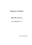
Figure 1-1 depicts the architecture of the BBS software.
Figure 1-1
BBS Architecture
BBS for the ATCA-7367 consists of the following main software and services:
20
Firmware Upgrade Facility
The Firmware Upgrade Facility (FUF) provides a uniform way to upgrade firmware on
Artesyn blades, regardless on which flash locations the firmware is stored. FUF upgrades
the BIOS firmware as well as the IPMC firmware (via HPM agent). The FUF currently consists
of a Firmware Upgrade Command Line Utility (FCU), flash device drivers, and specially
prepared firmware recovery image files. The FUF can be used on switch and node blades.
Linux Operating System
Wind River Enterprise Linux 3.0 (Carrier Grade Linux) is the operating system for BBS blades
and modules. The operating system comes with kernel 2.6.27. Various Linux services
(above the kernel) will be activated by the BBS installation scripts.
Hardware Platform Management
Hardware Platform Management (HPM) in AdvancedTCA systems is based on Intelligent
Platform Management Interface specification (IPMI). IPMI commands can be complex and
cumbersome. Using a certain set of commands, HPM facilitates the blade or module-level
hardware management.
Basic Blade Services Software on ATCA-7367 Programmer’s Reference (6806800K69F)
Introduction
SNMP Agent
As each BBS blade is individually managed, the default installation script installs and
initializes the "Net-SNMP" agent.
HPI-B
This release contains an RPM which contains all files necessary for developing HPI-B
applications. For further information refer to the System Management Interface Based on
HPI-B (Centellis 2000/4440) User’s Guide.
Clock agent package
The clock agent package supports configuration and operation of the telecom clock
functionality on the ATCA-7367 board.
Link Health Check
The Link Health Check (LHC) supports the configuration and operation of the LHC
protocol. LHC performs the verification of Layer 2 connectivity and the distribution of the
active network plane.
Basic Blade Services Software on ATCA-7367 Programmer’s Reference (6806800K69F)
21
Introduction
22
Basic Blade Services Software on ATCA-7367 Programmer’s Reference (6806800K69F)
Chapter 2
Installing the Basic Blade Services Software
2.1
Overview
Artesyn provides software images, including software updates, to its licensed customers. In
order to obtain the latest BBS software versions, contact your local sales representative.
Generally, there are three typical ways of installing/booting the BBS software on ATCA-7367:
Diskless client boot via network
Installation and booting from SATA/SAS hard disk
Installation and booting from on-board USB disk
On ATCA-7367 the SAS-HDD and SATA-HDD can reside in the AMC Bay or RTM when RTMATCA-7360-X installed. AMC Bay also supports SATA-HDD AMC without the installation of
any RTMs. As an option a Solid State Disk (SSD) with SATA interface (SATA cube) can be placed
on the front board.
For all these options you need to set up an external TFTP server to retrieve the required BBS
files. Furthermore you need to do some initial configurations. Table 2-1 provides an overview
of the main steps you need to take for the three installation/boot options. The detailed
procedures can be found in the following sections.
Table 2-1 BBS Installation/Boot Options - Main Set-Up and Configuration Steps
Installation/Boot Option
Main Set-Up and Configuration Steps
Diskless client boot. Refer
Configuring ATCA-7367 for
Diskless Client Boot of the BBS
Software on page 33.
1.
Set up and configure external TFTP boot server
2.
Configure DHCP server
3.
Configure PXE boot options
4.
Configure ATCA-7367 BIOS to boot from network
Installation and booting from
SATA/SAS hard disk. The hard
disk can be located on the RTM
or locally (as SATA cube) on the
front board. Refer Installing BBS
Software on Hard Disk Drive on
page 34.
1.
Set up and configure external TFTP boot server
2.
Configure DHCP server
3.
Configure PXE boot options
4.
Configure ATCA-7367 BIOS for network boot
5.
Boot BBS initrd image
6.
Install BBS image on hard disk (via install script)
7.
Configure ATCA-7367 BIOS to boot from hard disk
Basic Blade Services Software on ATCA-7367 Programmer’s Reference (6806800K69F)
23
Installing the Basic Blade Services Software
Table 2-1 BBS Installation/Boot Options - Main Set-Up and Configuration Steps (continued)
Installation/Boot Option
Main Set-Up and Configuration Steps
Installation and booting from
on-board USB flash. Refer
Installing BBS Software on OnBoard USB Disk on page 38.
1.
Set up and configure external TFTP boot server
2.
Configure DHCP server
3.
Configure PXE boot options
4.
Configure ATCA-7367 BIOS for network boot
5.
Boot BBS initrd image
6.
Install BBS image on USB flash (via install script)
7.
Configure ATCA-7367 BIOS to boot from USB flash
For more information about the rpm command, see its man page.
2.1.1
Installation Scripts
The following table describes the installation scripts required for installing the operating
system and blade utilities for ATCA-7367. These installation scripts require a TFTP and a DHCP
server to download the installation files.
Table 2-2 Installation Scripts
24
linuxrc
flashrfsrc
flashrc
Installed packages
Kernel, RFS and additional
packages
Kernel, RFS and
additional packages
Kernel, Ramdisk
(including BBS
packages)
Features
Enhanced partition
layout, SMART-/
Timezone and NTP
configuration,
Autoconfig
Simple partition
layout and
autoconfig
Timezone-/NTP
configuration
Suitable for devices
HDD, SSD > 30 GB
HDD, SSD or onboard USB flash
On-board USB flash or
USB stick
Basic Blade Services Software on ATCA-7367 Programmer’s Reference (6806800K69F)
Installing the Basic Blade Services Software
2.1.2
Package Information
BBS software is packaged with the Red Hat Package Manager (RPM) and is installed as part of
the standard installation. In general, you will not need to install or upgrade an individual
package.
The BBS distribution contains the following packages.
Table 2-3 BBS Distribution Packages
Description
File Name
Operating System Kernel (Kernel
version 2.6.27)
kernel
Ramdisk image for netboot
ramdisk.image.gz
Hard Disk Installation
Root file system for hard disk
installation
rootfs.tar.gz
Kernel command line
default.bbs-atca7367
Check sum of all files and RPMs
files.sha1sum
BIOS package
bbs-cpu-atca7367-<version>.rpm
IPMI firmware package (front
blade)
bbs-ipmc-atca7367-amc-poped-<version>.rpm
bbs-ipmc-atca7367-amc-no-poped<version>.rpm
bbs-ipmc-atca7367-c01-<version>.rpm
IPMI booter package (front blade)
bbs-ipmc-amc-poped-boot-atca7367<version>.rpm
bbs-ipmc-amc-nopoped-boot-atca7367<version>.rpm
bbs-ipmc-atca7367-c01-boot-<version>.rpm
IPMI firmware package (RTM)
bbs-artm-atca7360-<version>.rpm
IPMI firmware booter package
(RTM)
bbs-artm-boot-atca7360-<version>.rpm
FPGA firmware package
bbs-fpga-atca7367-<version>.rpm
Firmware Upgrade functionality Upgrade tool for BIOS, FPGA and
IPMC on front blade and RTM
bbs-fuf-atca7367-<version>-pne30.rpm
Basic Blade Services Software on ATCA-7367 Programmer’s Reference (6806800K69F)
25
Installing the Basic Blade Services Software
Table 2-3 BBS Distribution Packages (continued)
Description
File Name
Hardware Platform Management
consisting of daemon and client
bbs-hpmagentcmd-atca7367-<version>pne30.rpm
Flash driver for SFMEM module
bbs-sfmem-atca7367-<version>-pne30.rpm
Persistent RAM driver
bbs-pram-atca7367-<version>-pne30.rpm
Link Health Check
bbs-lhc-atca7367-<version>-pne30.rpm
Board control utility to get FPGA
data
bbs-boardctrl-atca7367-<version>pne30.rpm
Telecom clock routing signaling
configuration utility
bbs-clkagentcmd-atca7367-<version>pne30.rpm
HPI-B package
bbs-hpib-<version>-wrspne3.0-linux.rpm
HPI-B client package
bbs-hpib-clientsrc-<version>-wrspne3.0linux.rpm
HPI-B developer package
bbs-hpib-devel-<version>-wrspne3.0linux.rpm
Flashrom package (update tool for
BIOS flash via SPI interface)
bbs-flashrom-atca7367-<version>-pne30.rpm
Kdump Supporting Files
Statically linked Linux kernel
executable file which includes
vmlinux
the necessary information to make
the kernel.
26
Dump-capture kernel
kernel-kdump
Dump-capture kernel modules
modules4kdump.tar.bz2
Basic Blade Services Software on ATCA-7367 Programmer’s Reference (6806800K69F)
Installing the Basic Blade Services Software
The following rpm commands are useful to review package information.
2.1.3
Command
Description
rpm -qa
List all installed packages. Use rpm -qa | grep hpi to list only
HPI packages.
rpm -ql <package-name>
List the content of a package, where package-name is the name
of a specific package, for example, rpm -ql openhpi.
rpm -qi <package-name>
List information about a package, where package-name is the
name of a specific package, for example, rpm -qi openhpi.
rpm -qf <path to file>
Finds out which RPM a file belongs to.
Accessing the ATCA-7367 via Serial Console
In most procedures described in the following sections you need to invoke Linux commands or
configure BIOS settings. In order to do this, you need to access the ATCA-7367 via the face plate
serial port. If using a serial console or terminal emulator, the default serial port settings are:
9600 baud
No parity
Eight data bits
One stop bit
Flow control: xon/xoff
Emulated terminal type: VT100
If you wish to access Linux via a Linux shell, the default account login is root with the password
root. Refer Login on page 43, for more information.
2.2
Configuring TFTP, DHCP and PXE
For all installation and boot options, you need to set up and configure a TFTP server.
Furthermore, for the diskless client and hard disk installation/boot option, you need to
configure the system’s DHCP server and configure PXE boot options. All related steps are
described in the following section.
Basic Blade Services Software on ATCA-7367 Programmer’s Reference (6806800K69F)
27
Installing the Basic Blade Services Software
2.2.1
Create /tftpboot Directory and Copy Target Files
It is customary to place TFTP files in a tftpboot directory. Regardless of the file system node
you specify as the root for your TFTP service, the installation scripts expect a certain directory
structure when retrieving files.
Creating the /tftpboot Directory and Copying the Target Files
To create the expected directory structure and copy the needed files, follow these steps.
1. On the host create a /tftpboot directory, if it does not already exist
mkdir /tftpboot
2. Create a subdirectory for ATCA-7367, for example:
mkdir /tftpboot/atca-7367
3. Depending on the boot/installation option, copy or move the required installation
files to the subdirectory. Refer Table 2-3 on page 25 for BBS distribution packaging.
The exact file names in your BBS release may be different. Refer the release notes applicable
to your particular release. Table 2-3 on page 25 is only an example of a possible packaging
with example file names.
Please ensure that the file attributes are set to 755, so that PXE can access and load the files.
To ensure that the downloaded files are correct, sha1 checksums are used. If the
sha1 checksums are not correct, an error message is displayed during the installation process.
If you make changes to any of the files, you need to remember to update the sha1 checksum
file as well. If you still get an error message during the installation, it is likely that one or more
of the files have not been copied successfully. Copy all the files to the tftpboot directory
again and restart the installation.
2.2.2
Configuring a TFTP Server
The instructions in this section can be used to configure standard TFTP servers (BSD
compatible) that are under the control of xinetd. The exact configuration settings depend on
the particular system configuration, the following instructions are only meant as a general
guideline.
28
Basic Blade Services Software on ATCA-7367 Programmer’s Reference (6806800K69F)
Installing the Basic Blade Services Software
Configuring a TFTP Server
To configure TFTP as root on the host, complete the following steps:
1. Create (or edit) the file /etc/inetd.d/tftp. Depending on the particular
system environment, it may contain the following entries.
#/etc/inetd.d/tftp
service tftp
{
socket_type = dgram
wait = yes
user = root
log_on_success += USERID
log_on_failure += USERID
server = /bin/in.tftpd
server_args = -r blksize /tftpboot
disable = no
protocol = udp
}
2. Create the directory /tftpboot and add the needed files as described in Create
/tftpboot Directory and Copy Target Files on page 28.
3. If there are any TFTP daemons that have not timed out, you need to stop them.
Enter the following command to do so:
killall in.tftpd
4. Enter the following command to have inetd re-read its configuration file:
/etc/rc.d/init.d/inetd restart
Your TFTP server is now configured.
2.2.3
Configuring DHCP
The DHCP configuration file on an TFTP server (for example ATCA-F120 or an external TFTP
server) resides in /etc/dhcpd.conf. Make sure this file contains the following entries (IP
addresses may be different in your configuration):
Basic Blade Services Software on ATCA-7367 Programmer’s Reference (6806800K69F)
29
Installing the Basic Blade Services Software
#
# Sample dhcpd configuration file
#
#
allow bootp;
allow booting;
authoritative;
filename "pxelinux.0";
ddns-update-style ad-hoc;
option domain-name "booting.com";
option subnet-mask 255.255.255.0;
default-lease-time 600;
max-lease-time 7200;
#Base 1 interfaces
subnet 192.168.21.0 netmask 255.255.255.0 {
range 192.168.21.100 192.168.21.125;
option broadcast-address 192.168.21.255;
}
#Base 2 interfaces
subnet 192.168.22.0 netmask 255.255.255.0 {
range 192.168.22.100 192.168.22.125;
option broadcast-address 192.168.22.255;
}
#Front interfaces
subnet 192.168.19.0 netmask 255.255.255.0 {
range 192.168.19.100 192.168.19.125;
option broadcast-address 192.168.19.255;
}
Restart DHCP service on your Linux DHCP server by issuing the following commands and make
sure your DHCP service starts successfully against your configuration files:
30
Basic Blade Services Software on ATCA-7367 Programmer’s Reference (6806800K69F)
Installing the Basic Blade Services Software
#/etc/init.d/dhcp stop
#/etc/init.d/dhcp start
2.2.4
Configuring PXE
PXE determines which kernel and root file system image a blade gets from the server. The PXE
environment as well as the bootable images usually reside in the /tftpboot directory on the
server. The initial boot file is called pxelinux.0 and the PXE configuration directory is in the
/tftpboot/pxelinux.cfg. The default configuration file is called
/tftpboot/pxelinux.cfg/default.
Example default file:
DEFAULT ATCA7367/kernel ramdisk_size=716800 console=ttyS0,9600n8
initrd=ATCA7367/ramdisk.image.gz root=/dev/ram0 ip=none ro pci=lastbus=255
quiet
In this configuration, the same images are served to all blades in the chassis. In order to
distinguish between blades and to serve different images, you can use different default files
and link them to different’ MAC addresses of different blades.
Depending on the particular BBS release, an example default file for the ATCA-7367 may be
contained in the BBS package (check the release notes applicable to your blade release). This
file contains all required kernel parameters. In order to use the default file, you need to link it
to the MAC address of the ATCA-7367 as described below.
Basic Blade Services Software on ATCA-7367 Programmer’s Reference (6806800K69F)
31
Installing the Basic Blade Services Software
Example:
The following example shows how to set up the PXE environment for an ATCA-7367 blade. This
is done by creating a new default file and linking it to the MAC address of the ATCA-7367 boot
Ethernet interface, which is 00:80:42:1d:da:07 in the example.
PXE expects that the file name should be prefixed with "01" and all the characters in the file
name are lower case letters.
Setting up the PXE Environment
Proceed as follows:
1. Make a new subdirectory in /tftpboot
#mkdir -p /tftpboot/ATCA7367
2. Copy the corresponding boot image and RPMs to this directory.
3. Set up a new default files in /tftpboot/pxelinux.cfg, for example
default.7367.
The contents of default.7367 are:
DEFAULT ATCA7367/kernel ramdisk_size=600000
console=ttyS0,9600 initrd=ATCA7367/ramdisk.image.gz
root=/dev/ram0 rw
4. Link the MAC address of the blade to its boot default file, for example:
#cd /tftpboot/pxelinux.cfg
#ln -s default.7367 01-00-80-42-1d-da-07
2.3
Installation Procedures
The following subsections list the different BBS installation procedures.
32
Basic Blade Services Software on ATCA-7367 Programmer’s Reference (6806800K69F)
Installing the Basic Blade Services Software
2.3.1
Configuring ATCA-7367 for Diskless Client Boot of the BBS
Software
This section describes the steps you need to take for performing diskless client boot of the BBS
software.
Configuring BIOS for Diskless Client Boot
To configure BIOS for diskless client boot, proceed as follows:
1. Connect to the blade via the serial interface.
2. Power up or reboot the blade.
3. Quickly hold down the <F2> key on your keyboard until the BIOS menu appears.
4. Select ADVANCED on the top menu.
5. Scroll down to BOOT FEATURES by using the arrow keys.
6. Press <ENTER>.
7. Make sure that the following settings are enabled:
Base-Interface Network boot or Front Panel Network Boot
(depending on the interface you want to boot from).
If any of these settings is disabled, enable the setting(s) and press <F10> or select
Exit Saving Changes. This will save the new settings and restart the BIOS.
After the restart, press <F2> to enter BIOS again and continue with the BIOS
configuration.
8. Depending on which interface you want to boot from, put either Base Network
1, Base Network 2, or FrontPanel Network to the first position of the
Boot priority order list.
9. Save and exit.
Basic Blade Services Software on ATCA-7367 Programmer’s Reference (6806800K69F)
33
Installing the Basic Blade Services Software
Rebooting the Blade
To reboot a blade, proceed as follows:
1. Reboot the blade via:
Shelf manager
Opening and closing the lower handle switch on the face plate
Pressing the reset button on the face plate
2. Observe that the blade is getting a DHCP address and is loading the kernel and
ramdisk image:
Try to load: pxelinux.cfg/<address>
boot:
Loading <blade/module>/kernel..............
Loading <blade/module>/ramdisk-image.gz....
3. Once the blade has fully come up, log on to the serial console as root with the
default password root.
2.3.2
Installing BBS Software on Hard Disk Drive
This section describes how to install and boot the BBS software from hard disk. The BBS
software can be installed on the following hard disk types:
SAS/SATA hard disk drive installed on RTM or
SATA cube on front board (optional)
The installation process starts with the booting of an initial ramdisk via network. The initial
ramdisk is then used to copy (via TFTP) and interactively install the kernel, the root file system,
and other BBS software on the disk.
The following procedures describe these steps in detail.
34
Basic Blade Services Software on ATCA-7367 Programmer’s Reference (6806800K69F)
Installing the Basic Blade Services Software
Configuring BIOS for Diskless Network Boot
To configure BIOS for network boot, proceed as follows:
1. Connect to the blade via the serial interface.
2. Power up or reboot the blade.
3. Quickly hold down the <F2> key on your keyboard until the BIOS menu appears.
4. Select ADVANCED on the top menu.
5. Scroll down to BOOT FEATURES by using the arrow keys.
6. Press <ENTER>.
7. Make sure that the following settings are enabled:
Base-Interface Network boot or Front Panel Network Boot
(depending on the interface you want to boot from).
If any of these settings is disabled, enable the setting(s) and press <F10> or select
Exit Saving Changes. This will save the new settings and restart the BIOS.
After the restart, press <F2> to enter BIOS again and continue with the BIOS
configuration.
8. Depending on which interface you want to boot from, put either Base Network
1, Base Network 2, or FrontPanel Network to the first position of the
Boot priority order list.
9. Save and exit.
Installing Files and Configuring TFTP on the ATCA-7367
After the system has come up, install Linux with the following procedure:
1. Login as root.
2. Identify the Linux device name of the hard disk on which you want to install BBS.
To do so, enter fdisk -l. This displays available hard disks, their Linux device
names and also the storage capacity.
Basic Blade Services Software on ATCA-7367 Programmer’s Reference (6806800K69F)
35
Installing the Basic Blade Services Software
3. Run the linuxrc script from the /opt/bladeservices/tools directory:
./linuxrc
The hard disk installation begins by checking for necessary commands on the
system.
4. Enter the information requested by the script, such as the TFTP server address from
where the software is loaded, NTP server address, and time zone.
5. Above steps installs all the BBS packages that are available after tftpboot and
Linux
Boot loader, on the hard disk.
Refer Installing BBS Using Hard Disk on page 181, for step-wise output of the installation and
configuration procedure.
Performing the Final Configuration on the ATCA-7367
The final configuration includes configuring the host name and password and setting the time
zone.
1. Configure the host name:
Choose a hostname for this machine [ ]
There is no default hostname. Enter a value here.
2. Configure the root password:
Enter new UNIX password:
Retype new UNIX password:
There is no default root password.
Now the boot loader grub is installed. After that you need to configure BIOS to boot from the
hard disk as described in the following procedure.
Configuring the ATCA-7367 BIOS to Boot from Hard Disk
To configure BIOS on an ATCA-7367 blade, proceed as follows:
1. Connect to the blade via the serial interface.
2. Power up or reboot the blade.
36
Basic Blade Services Software on ATCA-7367 Programmer’s Reference (6806800K69F)
Installing the Basic Blade Services Software
3. Quickly hold down the <F2> key on your keyboard until the BIOS menu appears.
4. Select BOOT on the top menu.
5. Scroll down to BOOT OPTIONS by using the arrow keys.
6. Press <ENTER>.
7. Depending on the hard disk type and the location where the hard disk is installed,
make sure that the corresponding BIOS setting shown in the following table is
enabled.
Hard Disk
BIOS Menu and Setting Which Must Be Enabled
SAS hard disk installed on RTM
“Boot Features” -> "ARTM SAS boot"
If the desired setting was previously NOT enabled, enable the desired setting and
press <F10> or select Exit Saving Changes. This will save the new settings
and restart the BIOS. After the restart, press <F2> to enter BIOS again and continue
with the BIOS configuration.
8. Put the hard disk which you want to boot from to the first position of the Boot
priority order list.
9. Save and exit.
After a successful reboot, you can logon as root using the password you have
defined during the final configuration.
Basic Blade Services Software on ATCA-7367 Programmer’s Reference (6806800K69F)
37
Installing the Basic Blade Services Software
2.3.3
Installing BBS Software on On-Board USB Disk
The ATCA-7367 BBS supports network boot via tftp. You can use flashrfsrc script to
install the root file system on the ATCA-7367 on-board flash and to boot from it. The
flashrfsrc script performs the following tasks:
formats the ATCA-7367 on-board flash device
transfers the kernel, root file system, and BBS packages from the tftp server to the onboard flash device
installs and configures the GRUB boot loader
Executing the flashrfsrc script will erase all the data existing on the on-board flash.
Configuring BIOS for Diskless Network Boot
To configure BIOS for network boot, proceed as follows:
1. Connect to the blade via the serial interface.
2. Power up or reboot the blade.
3. Quickly hold down the <F2> key on your keyboard, until the BIOS menu appears.
4. Select BOOT on the top menu.
5. Scroll down to BOOT OPTIONS by using the arrow keys.
6. Press <ENTER>.
7. Ensure that the following settings are enabled:
Base Network 1, Base Network 2, or FrontPanel Network; depending
on the interface you want to boot from.
If any of these settings is disabled, enable the setting(s) and press <F10> or select
Exit Saving Changes, to save the new settings and restart the BIOS. After the
restart, press <F2> to enter BIOS again and continue with the BIOS configuration.
38
Basic Blade Services Software on ATCA-7367 Programmer’s Reference (6806800K69F)
Installing the Basic Blade Services Software
8. Depending on which interface you want to boot from, put either Base Network
1, Base Network 2, or FrontPanel Network to the first position of the Boot
priority order list.
9. Save and exit.
Installing Root File System on the on-board Flash
To install the OS and BBS software on the on-board flash of RTM-ATCA-7360 module:
1. Start the blade using tftp-boot.
2. Execute flashrfsrc script (available in the directory of
/opt/bladeservices/tools/) after an initial netboot. It allows an automatic
installation of the OS and BBS packages on the on-board USB flash disk. Provide the
device name on which the software is to be installed when you are prompted for it.
You can modify the configuration file flashConfig.default as per your
requirement and use it for the installation.
3. Enter the information requested by the script, such as the TFTP server address from
where the software is loaded, NTP server address, and time zone.
4. Above steps installs all the BBS packages that are available after tftpboot and
Linux Boot loader, on the hard disk.
5. Reboot the blade.
6. Press <F2> to configure the BIOS.
7. In the Boot menu, move onboard:USBHdd SMART eUSB to the first option in
the Boot Priority Order list.
8. Save and exit BIOS settings and continue booting.
After successful installation, the OS is loaded from the on-board USB flash disk drive.
Refer Appendix A, Installing and Configuring BBS, on page 181, for step-wise output of the
installation and configuration procedure.
Basic Blade Services Software on ATCA-7367 Programmer’s Reference (6806800K69F)
39
Installing the Basic Blade Services Software
2.4
Upgrading the Software
Software updates are usually delivered as rpm-files. To install the files on the disk of the blade,
copy the new RPM file to the blade, stop the application using this rpm, remove the original
files (using the rpm -e <package> command) and install the newly copied rpm (using the
command rpm -Uvh <package-name> command).
To upgrade the BBS software for diskless clients, you have to delete the installation files in the
/tftpboot directory on the tftpserver, copy the new installation files into this directory, and
follow the instructions in Configuring ATCA-7367 for Diskless Client Boot of the BBS Software on
page 33.
2.5
Adapting the BBS Software to Customer’s Needs
The BBS software structure allows a maximum flexibility with regards to customer’s
adaptations. Software packages can easily be installed into or removed from existing
installations.
The following adaptations are possible:
2.5.1
Modifying the NetBoot root file system
Modifying the hard disk installation
Modifying the hard disk installation procedure
Modifying the Configuration of the Artesyn-Supplied CGL Kernel
Modifying the NetBoot Root File System
The netBoot root file system is stored in the file ramdisk.image.gz on the TFTP server. In
order to change the system’s behavior regarding network booting blades, you have to modify
the root file system.
As root:
#
#
#
#
40
cd /tftpboot/<blade or module to be modified>
mkdir mnt
gunzip ramdisk.image.gz
mount -o loop ramdisk.image mnt
Basic Blade Services Software on ATCA-7367 Programmer’s Reference (6806800K69F)
Installing the Basic Blade Services Software
# pushd mnt
# ..... /* make all modifications and enhancements: delete, add or
change files*/
# popd
# unmount mnt
# gzip -9 ramdisk.image
The blade will now boot the modified root file system.
2.5.2
Modifying Hard Disk Installation
The hard disk installation can be changed after the blade has been installed or by modifying the
file rootfs.tar.gz prior to the installation. After modifying this file, you have to compute
and add the sha1 checksum of the modified root file system to the files.sha1sum in the
installation directory on the TFTP server.
The example below shows how to change the default login behavior.
# cd /tftpboot/...
(cd to the directory containing the
rootfs.tar.gz you want to modify)
# mkdir rootfs
# cd rootfs
# tar xzf ../rootfs.tar.gz
* Make your modifications and enhancements to the root filesystem
in the current directory
# tar czf ../rootfs.tar.gz .
# cd ..
# sha1sum rootfs.tar.gz
*Correct the sha1sum for rootfs.tar.gz in files.sha1.sum
2.5.3
Modifying the Hard Disk Installation Procedure
The hard disk installation procedure is based on the files.sha1sum in the installation
directory on the TFTP server. All packages which are copied to the blade during installation are
listed in the files.sha1sum together with their sha1sum. The standard installation process
accepts rpm, tar, and tgz files and all files that have "kernel" in the file name.
Basic Blade Services Software on ATCA-7367 Programmer’s Reference (6806800K69F)
41
Installing the Basic Blade Services Software
The packages from files.sha1sum are installed in the same sequence as listed in the file
files.sha1sum. The installation process re-calculates the sha1sum of the packages on the
blade and compares it to the sha1sum determined by files.sha1sum. This ensures a
protection against errors and faults during file transmission. The user will be notified in case of
mismatch. In that case, you have to repeat the installation procedure.
The root file system must precede the rpm files in the files.sha1sum file.
2.5.4
Modifying the Configuration of the Artesyn-Supplied PNE Linux
Kernel
The current kernel configuration of a running ATCA-7367 installation can be retrieved using the
Linux command zcat /proc/config.gz or from
ATCA7367_custom_layer/template/board/atca7367/linux/atca7367.cfg in
the LSP directory of the Release package.
To modify the configuration of the CGL kernel supplied by Artesyn, consult your local Artesyn
sales representative for assistance and further information.
42
Basic Blade Services Software on ATCA-7367 Programmer’s Reference (6806800K69F)
Chapter 3
Linux Distribution Description
3.1
Distribution Description
The BBS for the ATCA-7367 is based on Wind River Enterprise Linux 3.0, which is a Linux
distribution built on Linux 2.6.27 kernel technology.
3.2
Reliability
The hard disk installation is configured to use the journaling file system ext3. In this
distribution majority of errors that are caused due to improper shutdown are fixed
automatically during the boot process. Catastrophic errors that cannot be fixed automatically
will yield to a command prompt, allowing the super user to execute the fsck command on the
affected partition.
3.3
Login
A Linux shell can be accessed via the face plate serial port.
If you use a serial console or terminal emulator, the serial/RTM port settings are 9600 baud, no
parity, 8 data bits, and 1 stop bit.
If you use secure shell server, it starts in run levels 2–5 and listens on all the Ethernet interfaces.
Root login for ssh is not permitted, you need to log in as user "admin". Refer Network Services
Configuration on page 47 for default IP address assignments.
If you want to login as root via SSH, you need to first configure SSH using the console serial
port. Set PermitRootLogin in the file /etc/ssh/sshd_config to yes. For this to take
effect you must either reboot the blade or run the command /etc/init.d/ssh restart.
The following table lists available default login accounts.
Login Name
Password
Description
admin
emerson
Non-privileged user account
root
root
Privileged user account
Basic Blade Services Software on ATCA-7367 Programmer’s Reference (6806800K69F)
43
Linux Distribution Description
3.4
Long POST/Diagnostics
The long POST (Power-On Self test) is an extension to the standard POST which the ATCA-7367
executes after power-up. It is executed during the booting of the Linux operating system and
includes higher-level tests. This section describes which tests are by default executed during
the long POST, how to obtain the results of these tests and how to add your own test routines.
3.4.1
Default Test Routines
The long POST test routines are implemented as Linux scripts which are invoked during the
Linux boot phase. The test scripts which are to be executed need to be defined in the IPMI boot
parameter variable runLP or as additional parameter in the kernel command line
(runLP=…,…,). Further details are given in Configuring the Long POST Behavior on page 45.
Each test routine displays the test status on the console and writes it to the Linux log module
(via logger). Furthermore, each test routine writes status information to the IPMI sensor
"System Firmware Progress" (type 0xF0). The used event data values are Artesyn-specific. The
following table provides details.
Table 3-1 Long POST Standard Test Routines - Generated IPMI Data
Action
Data Written to System Firmware Progress Sensor
Test routine is started
Offset 0: 0x02
Offset 1: 0xFD
Offset 2: 0x1E
Tests routine detects an error.
Offset 0: 0x00
Offset 1: 0xFD
Offset 2: 0x1E
The following table lists the names of the default long POST test routines and describes which
tests each routine performs.
Table 3-2 Long POST Default Test Routines
44
Test Routine Name
Description
cpuspeed
This tool gives an overview on the active performance governors and the
frequency per core.
Basic Blade Services Software on ATCA-7367 Programmer’s Reference (6806800K69F)
Linux Distribution Description
Table 3-2 Long POST Default Test Routines (continued)
3.4.2
Test Routine Name
Description
memSize
Checks the amount of memory physically installed and the memory
seen by the Operating system.
rtctest
Tests the functionality of the real time clock.
eccTest.sh
This scripts tests checks the ECC Error counter in the memory controller.
Configuring the Long POST Behavior
The names of the test scripts which are to be executed have to be defined in the IPMI system
boot parameter variable runLP as a comma-separated list, for example as follows:
runLP=cpuspeed,memSize.sh,rtctest,eccTest.sh
The scripts are expected to be located in the following directory:
/opt/bladeservices/tools/LP. So in order to add your own scripts, simply add an entry
to the IPMI boot variable runLP or add an appropriately defined kernel boot parameter runLP
and place the script(s) in /opt/bladeservices/tools/LP. Depending on your system
configuration, you may want to design your test scripts to generate console output, write to
the log module and store any results in the IPMI System firmware progress sensor as done by
the default test scripts.
The IPMI boot parameter can be set by using the hpm command bootparamset (hpm -c
bootparamset).
When Linux is booted, the Linux start-up script /etc/init.d/LPmain.sh is executed. It
reads and analyses the IPMI boot parameter variable runLP and invokes the listed test scripts
(if any) in the given order. For more advanced customizations, you may want to modify the
/etc/init.d/rd.d/LPmain.sh script.
Basic Blade Services Software on ATCA-7367 Programmer’s Reference (6806800K69F)
45
Linux Distribution Description
The LPmain.sh provides the following options:
Table 3-3 Long POST Script LPmain.sh - Options
3.5
Option
Description
start
Starts the Long POST for the specified test cases.
status
Gives information about the test cases to be executed during long POST and
shows whether longPOST is switched on.
enableLP
Enables the long POST. The Long POST will be executed during the next OS
startup.
disableSP
Disables the long POST. The long POST will not be executed during the next OS
startup.
Linux Services Initialization
Table 3-4 describes the generic Linux run levels. Table 3-1 describe the services configured to
start in the various Linux run levels. Per default, the blade first runs run level S and then boots
into run level 3 as configured by the factory.
Table 3-4 Generic Linux Run Levels
46
Run Level
Description
S
Startup
0
Halt system
1
Single-user mode
2
Multiuser mode
3
Multiuser mode with network (default)
4
Not used
5
Not used
6
Reboot system
Basic Blade Services Software on ATCA-7367 Programmer’s Reference (6806800K69F)
Linux Distribution Description
3.5.1
RC Scripts
In addition to the rc-scripts of the Wind River PNE 3.0 Linux configuration the following
start/stop scripts are added to ATCA-7367.
Run
Level
Script Name
Description
rc3.d
S01bbsrpms
Installs bbs-rpms during initial blade startup, for example,
after blade installation or boot via network boot.
S02bbsinit
Starts boardctrl driver and the optional persistent memory
drivers (pram and sfmem when the optional memory
module is installed).
S03longPost
Performs some basic blade tests, before most of the OS
services are started.
S09hpm
Starts the hpmagent.
S10ethDevOrdering
Performs the eth-device reordering and renaming.
S20kdump
The kdump service script.
S57bbsvlan
Configures ip-addresses for the fabric interfaces and brings
up the base and fabric interfaces.
K05hpm
Stops the hpmagent.
rc6.d
3.6
Network Services Configuration
The following sections describe the default configuration for network services.
3.6.1
ATCA-7367 Ethernet Interfaces
The ethernet devices, such as eth0, eth1, and eth2 in Linux distribution are renamed to more
meaningful name in ATCA-7367, such as base1, base2, and fabric1. This renaming is done in
the /etc/init.d/ethDevOrdering.sh script, before the network startup.
Basic Blade Services Software on ATCA-7367 Programmer’s Reference (6806800K69F)
47
Linux Distribution Description
The following table specifies the Ethernet devices supported by ATCA-7367.
Device
Name
Description
Speed
Location
IP address
base1
Base
Interface 1
1GbE
Base blade ->
Backplane
Obtained by the DHCP client
request.
base2
Base
Interface 2
1GbE
Base blade ->
Backplane
Obtained by the DHCP client
request.
fabric1
Fabric
Interface 1
10GbE
Base blade ->
Fabric Interface on
Backplane
Static IP address.
It is computed as:
192.168.<fabricIf>.<slotn
umber*10>
fabricIf can have value of; ’11"
for Fabric Interface 1 and "12" for
Fabric Interface2.
slotnumber specifies the logical
slot number converted to decimal.
The setup of the IP Addresses for
Fabric IF is done in the
/etc/init.d/bbsvlan.sh file.
fabric2
Fabric
Interface 2
10GbE
Base blade ->
Fabric Interface on
Backplane
Static IP address.
It is computed as:
192.168.<fabricIf>.<slotn
umber*10>
fabricIf can have value of; "11"
for Fabric Interface 1 and "12" for
Fabric Interface2.
slotnumber specifies the logical
slot number converted to decimal.
The setup of the IP Addresses for
Fabric IF is done in the
/etc/init.d/bbsvlan.sh file.
48
Basic Blade Services Software on ATCA-7367 Programmer’s Reference (6806800K69F)
Linux Distribution Description
Device
Name
3.7
Description
Speed
Location
IP address
front
Front Panel
Interface
1GbE
Base blade
No IP address assigned.
update
Update
Channel
interface
1GbE
Base blade
No IP address assigned.
rtm1
RTM 1
1GbE
RTM (optional)
No IP address assigned.
.......
..........
........
......................
rtm6
RTM 6
1GbE
RTM (optional)
NOTE: The ethernet devices on RTM
are named from bottom to top on
the face blade.
amc1
AMC 1
1GbE
AMC
No IP address assigned.
.......
..........
........
.......
amc4
AMC 4
1GbE
AMC
NOTE: The AMC Ethernet interfaces
are only available on the ATCA7367 variants which have AMC Bay
Present.
Tools
This section describes CPUSpeed and IPMIBPAR tools that can be used to change the processor
performance governors and IPMI Boot Parameter list.
Basic Blade Services Software on ATCA-7367 Programmer’s Reference (6806800K69F)
49
Linux Distribution Description
3.7.1
Performance Tool
The performance tool, CPUSpeed allows to change the processor performance governors and
the core frequency (for userspace governor) on a per core base. It utilizes data stored in the
/sys/device/system/cpu directory. The following table describes various governors.
Governor
Description
Performance
Core is running with maximum frequency.
Ondemand
Cores in idle state are running at lowest frequency. When the core is
changed to the utilized state, the frequency of the core is changed to
maximum.
Powersave
Core is running with minimum frequency.
Userspace
Core frequency can be adjusted by the user (in steps).
If the P-States are limited by BIOS the required driver is not loaded and therefore the
CPUSpeed tool can not work.
CPUSpeed supports the following options:
50
Option
Description
-d
Dump CPU Frequency/Governor Info
-h
Help
-p
Print supported governors
-s
Set governor/frequency. It supports the following options:
-c : Specifies the core. Valid values are 0 .. 15. Omitting this option
means, all cores.
-f : Specifies the frequency. Valid values are 1596000 .. 2129000.
This parameter is ignored except for ’userspace governor’.
-g : Specifies governors, such as performance, powersave,
ondemand, and userspace.
Basic Blade Services Software on ATCA-7367 Programmer’s Reference (6806800K69F)
Linux Distribution Description
Example:
root@ATCA-7367:/opt/bladeservices/tools#
/opt/bladeservices/tools/cpuspeed
####### CPU Frequency Info #######
Number Of Cores: 12
MinFrequency:
1596000
MaxFrequency:
1730000
Available Governors: ondemand userspace powersave performance
####### Frequency Info Per Core #######
Core:
Governor:
CurrentFrequency:
0
performance
1730000
1
performance
1730000
2
performance
1730000
3
performance
1730000
4
performance
1730000
5
performance
1730000
6
performance
1730000
7
performance
1730000
8
performance
1730000
9
performance
1730000
10
performance
1730000
11
performance
1730000
Basic Blade Services Software on ATCA-7367 Programmer’s Reference (6806800K69F)
51
Linux Distribution Description
3.7.2
IPMIBPAR
The IPMIBPAR tool can be used to change the IPMI Boot Parameter list when Linux is up and
running. It supports the following options:
Option
Description
-d
Enable debug output.
-a xx
IPMB Address, if not present local IPMC is used.
-i
Get device ID.
-g
Get IPMI Boot Parameter USER area.
-s file
Store IPMI Boot Parameter (USER area), read from file.
-h
Help.
The following example describes the steps required to change the BootOrder from SAS-HDD
to Base Network1.
1. Read the IPMI boot parameter USER area from IPMC.
root@ATCA-7367:/opt/bladeservices/bin# ipmibpar -g
ipmibpar - Version 1.02 - IPMI Boot Parameter Demo
Copyright 2008 Emerson Network Power Embedded Computing Inc.
Read System Boot Options from USER area (local IPMC)
Hexdump IPMI Boot Parameter:
Size = 182 (0xb6)
52
0000 b2 00 62 61 75 64 72 61 74 65 3d 39 36 30 30 00
<..baudrate=9600.>
0010 75 73 62 3d 66 70 5f 6f 6e 2c 72 74 6d 5f 6f 6e
<usb=fp_on,rtm_on>
0020 2c 6f 6e 62 6f 61 72 64 5f 6f 6e 00 6f 73 5f 62
<,onboard_on.os_b>
0030 6f 6f 74 5f 77 61 74 63 68 64 6f 67 3d 6f 66 66
<oot_watchdog=off>
0040 2c 35 2c 72 65 73 65 74 00 66 72 6f 6e 74 6e 65
<,5,reset.frontne>
0050 74 5f 62 6f 6f 74 3d 6f 6e 00 62 61 73 65 6e 65
<t_boot=on.basene>
Basic Blade Services Software on ATCA-7367 Programmer’s Reference (6806800K69F)
Linux Distribution Description
0060 74 5f 62 6f 6f 74 3d 6f 6e 00 61 72 74 6d 5f 6e
<t_boot=on.artm_n>
0070 65 74 5f 62 6f 6f 74 3d 6f 66 66 00 61 72 74 6d
<et_boot=off.artm>
0080 5f 73 61 73 5f 62 6f 6f 74 3d 6f 6e 00 61 72 74
<_sas_boot=on.art>
0090 6d 5f 66 63 5f 62 6f 6f 74 3d 6f 66 66 00 62 6f
<m_fc_boot=off.bo>
00a0 6f 74 5f 6f 72 64 65 72 3d 66 72 6f 6e 74 6e 65
<ot_order=frontne>
00b0
74 00 00 00 1d 42
<t....B>
IPMI Boot Parameter:
baudrate=9600
usb=fp_on,rtm_on,onboard_on
os_boot_watchdog=off,5,reset
frontnet_boot=on
basenet_boot=on
artm_net_boot=off
artm_sas_boot=on
artm_fc_boot=off
boot_order=frontnet
2. Save the received IPMI Boot Parameter list into a file (for example, bootparam.log) and
change the boot order as follow.
baudrate=9600
usb=fp_on,rtm_on,onboard_on
os_boot_watchdog=off,10,reset
frontnet_boot=on
basenet_boot=on
Basic Blade Services Software on ATCA-7367 Programmer’s Reference (6806800K69F)
53
Linux Distribution Description
artm_net_boot=off
artm_sas_boot=on
artm_fc_boot=off
boot_order=basenet0,sashdd,basenet1,sashdd,usbonboard,frontnet
3. Write the IPMI parameter list file (for example, bootparam.log).
ipmibpar -s <filename>
54
Basic Blade Services Software on ATCA-7367 Programmer’s Reference (6806800K69F)
Chapter 4
Firmware Upgrade Facility
4.1
Overview
The Firmware Upgrade Facility (FUF) provides a uniform way to upgrade firmware on Artesyn
hub blades and node blades. It consists of a Firmware Upgrade Command-line Utility (FCU),
flash device drivers, and specially prepared firmware recovery image files. On the ATCA-7367
FUF allows you to upgrade the following firmware types:
4.2
BIOS firmware
IPMC firmware
MMC firmware on RTM
FPGA image
Firmware Recovery Image Files
FCU supports specially prepared firmware recovery image (FRI) files as well as firmware images
in the HPM.1 format. HPM.1 is a PICMG standard to upgrade IPMCs.
By default, the image files for the current hardware configurations are loaded as part of the BBS
software in /opt/bladeservices/rom when the blade-specific firmware support
packages are installed.
The following image files are currently supported.
Filename
Description
atca-7367-cpu-<version>.fri
BIOS image in FRI format
atca-7367-cpu-<version>.hpm
BIOS image in HPM.1 format
atca-7367-c01-ipmc.hpm
IPMC firmware for ATCA-7367 variant of ATCA7367-C01
atca-7367-amc-poped-ipmc.hpm
IPMC firmware for ATCA-7367 variants with Amc
Bay Present (Including ATCA-7367-0GB, ATCA7367-12GB, ATCA-7367-24GB).
atca-7367-amc-no-poped-ipmc.hpm
IPMC firmware for ATCA-7367 variants with AMC
Bay not present (Including ATCA-7367-0GB-LS,
ATCA-7367-12GB-LS).
atca-7367-ipmc-c01-boot.hpm
IPMC boot loader for ATCA-7367 variant of ATCA7367-C01
Basic Blade Services Software on ATCA-7367 Programmer’s Reference (6806800K69F)
55
Firmware Upgrade Facility
Filename
Description
atca-7367-ipmc-amc-popedboot.hpm
IPMC boot loader for ATCA-7367 variants with Amc
Bay Present (Including ATCA-7367-0GB,
ATCA-7367-12GB, ATCA-7367-24GB).
4.3
atca-7367-ipmc-amc-nopopedboot.hpm
IPMC boot loader for ATCA-7367 variants with AMC
Bay not present (Including ATCA-7367-0GB- LS,
ATCA-7367-12GB-LS).
atca-7367-fpga-<version>.bin
FPGA image in HPM.1 format
artm-7360-ipmc.hpm
IPMC Firmware for ARTM
artm-7360-ipmc-boot.hpm
IPMC boot loader for ARTM
Backup Concept
The BIOS firmware for the ATCA-7367 is stored in redundant, persistent memory devices. This
allows the firmware image in one bank to serve as a backup for the other bank. This is
particularly useful for firmware upgrades.
During normal operation, the CPU on the ATCA-7367 determines which bank to boot from
based on a chip select signal controlled by the IPMC. This bank is considered the active boot
device. FCU will only allow you to upgrade an inactive device. FUF allows you to upgrade only
the BIOS boot bank from which the blade has not booted. This means that you need to reboot
the blade in case you want to upgrade both the banks of the BIOS flash. The BIOS firmware
image can be programmed via the payload by using FUF or via IPMC.
The IPMC firmware consists of a boot loader as well as an active and a stand-by IPMI firmware.
The boot loader maintains both the active and stand-by firmware in the flash memory of the
ATCA-7367. Please note that the BootLoader Firmware is not installed in the BBS by default, as
the BootLoader update must be performed on Artesyn request only.
Each time the IPMC firmware is upgraded, the most recent firmware version is kept in flash
memory and the older firmware version is overwritten by the new one. Once the new IPMI
firmware is programmed, the IPMC resets itself to boot from the new image. The boot loader
validates the new IPMC firmware. Provided the IPMC can power up successfully the current
image is made active and the previously active image is made backup. In case of power-up
failures, the boot loader automatically recovers from crisis and boots from the previous image.
56
Basic Blade Services Software on ATCA-7367 Programmer’s Reference (6806800K69F)
Firmware Upgrade Facility
The FPGA bank can be updated via FCU or IPMC. This means that a corrupt FPGA image can be
restored using IPMC. Do remember NOT to power off the blade in case you failed to upgrade
the FPGA firmware. Otherwise, your blade may be malfunction or even cannot be powered up
due to a corrupted FPGA image. You may recover the corrupted FPGA image through IPMB
from shelf manger using ipmitool while the blade is still running.
The following sample output displays the information regarding BIOS, IPMI, and FPGA.
Depending on your setup, you may get a different output.
fcu -q
********************[[[[[REPORT BEGIN]]]]]********************
OPERATION : Query
RESULT
: SUCCESS
MESSAGE
: Device: atca-7367-cpu
Part number
: 0106865F08A....
Part revision
: R1.2.
BANK
: A
Firmware Name
: AMI-BIOS
Firmware Version
: 1.0.0
Marked for next use : no
--> Installed BIOS Version on Bank0
BANK
: B Firmware
Name
: AMI-BIOS
Firmware Version
: 1.0.0
Marked for next use : yes
--> Installed BIOS Version on Bank1
OPERATION : Query
RESULT
: SUCCESS
Basic Blade Services Software on ATCA-7367 Programmer’s Reference (6806800K69F)
57
Firmware Upgrade Facility
MESSAGE
: Device: atca-7367-hpm.1-ipmc
Part number
: 0106865F08A....
Part revision
: R1.2.
BANK
: A - Operational
Firmware Name
: H8S-AMCc F/W
Firmware Version
: 2.0.00000007
--> Currently activated IPMC firmware bank. Only readable to IPMC which has booted up with
it.
BANK
: B - Rollback
Firmware Name
: H8S-AMCc F/W
Firmware Version
: 2.0.00000007
--> Rollback IPMC firmware bank. The bank which will be wrote upon an IPMC firmware
upgrade request.
BANK
: D - Operational
Firmware Name
: H8S-AMCc B/L
Firmware Version
: 2.0.00000006
--> Installed IPMC FW Boot Loader. Single bank. Upgradeable.
BANK
: G - Operational
Firmware Name
: H8S-AMCc F/I
Firmware Version
: 0.0.00000000
--> Internal IPMI Bank (FRU Info). No subject to be updated!
58
BANK
: J - Operational
Firmware Name
: H8S-AMCc F/C
Firmware Version
: 0.0.00000000
Basic Blade Services Software on ATCA-7367 Programmer’s Reference (6806800K69F)
Firmware Upgrade Facility
--> Internal IPMI Bank (FRU Info Carrier). No subject to be updated
BANK
: M - Operational
Firmware Name
: FPGA
Firmware Version
: 0.0.0000000D
--> Installed FPGA Version. Single bank. Upgradeable.
BANK
: P - Operational
Firmware Name
: BIOS
Firmware Version
: 1.0.00000000
--> Inactive BIOS Version (seen by IPMC)
BANK
: S - Operational
Firmware Name
: BIOS
Firmware Version
: 0.0.00000000
--> Activated BIOS Bank (not seen by IPMC).
OPERATION : Query
RESULT
: SUCCESS
MESSAGE
: Device: artm-7360-hpm.1-ipmc
Part number
: unknown
Part revision
: unknown
IPMI address
: MMC=0x72
BANK
: A - Operational
Firmware Name
: AVR-AMCm F/W
Firmware Version
: 1.51.00000002
--> Installed IPMI FW for ARTM on Bank1
BANK
: B - Rollback
Basic Blade Services Software on ATCA-7367 Programmer’s Reference (6806800K69F)
59
Firmware Upgrade Facility
Firmware Name
: AVR-AMCm F/W
Firmware Version
: 1.51.00000002
--> Installed rollback IPMI FW for ARTM on Bank2
BANK
: D - Operational
Firmware Name
: AVR-AMCm B/L
Firmware Version
: 1.51.00000001
--> Installed IPMI Booter FW for ARTM
********************[[[[[ REPORT END ]]]]]********************
60
Basic Blade Services Software on ATCA-7367 Programmer’s Reference (6806800K69F)
Firmware Upgrade Facility
4.4
fcu—Firmware Upgrade Command-Line Utility
Description
The Firmware Upgrade Command-line Utility (FCU) allows you to
Query the current versions of firmware installed on the ATCA-7367 and determine which
firmware devices are active
Verify that a specified upgrade image is sound and compatible with the current hardware
Upgrade a firmware image
Mark a device to be used as the boot source on the next reset
Show the version of a specified firmware image file and compare the version of a specified
firmware image file with the version of an installed firmware image
By default, the FCU binary executable is installed in /opt/bladeservices/bin. This
directory has been added to the PATH environment variable.
FCU works in conjunction with device drivers created specifically for the flash devices on
Artesyn blades.
The FCU verify and upgrade operations require specially prepared FRI or HPM files (see
Firmware Recovery Image Files on page 55).
FCU also relies on the Hardware Platform Management Agent daemon to interact with the local
IPMC. Most commands will fail if the HPM Agent is not running. For information on configuring
and running HPM Agent, see Chapter 5, Hardware Platform Management, on page 73.
Synopsis
fcu --help
fcu --version
fcu -q [-d <device-id>]
fcu -v -f <filename>
fcu -u -f <filename>
fcu -a -f <filename>
fcu -m -b <bank-letter> -d <device-id>
Basic Blade Services Software on ATCA-7367 Programmer’s Reference (6806800K69F)
61
Firmware Upgrade Facility
Parameters
-a
--full-upgrade
This option is a shortcut for performing the verify, upgrade, and mark operations. The file
option -f is required. This option should not be combined with other operations.
-b <bank-letter>
--bank=<bank-letter>
Specifies the bank to mark for next boot, where <bank-letter> is the letter designating a
specific bank. For BIOS banks, possible values are A and B. For FPGA images, possible values are
B (default EEPROM) and C (user-programmable EEPROM). This option is used with the mark
operation. Use the query option -q to display available banks.
-c
-compare
Compares the image contained in the specified device with a specified file in the file system.
This may be useful after an image upgrade to verify that the device actually contains a new and
different image.
-d <device-id>
--device=<device-id>
Specifies a target firmware device, where <device-id> is the name of the device. This option
is used with the mark or query operations. Device ID values vary by hardware. You can display
supported devices on a given blade by using fcu --help. Currently supported values are
listed in the following table.
Device ID
Description
atca-7367-cpu
BIOS firmware image on ATCA-7367
atca-7367-hpm.1ipmc
IPMC firmware, RTM MMC firmware and FPGA image on ATCA7367
-f <filename>
--file=<filename>
62
Basic Blade Services Software on ATCA-7367 Programmer’s Reference (6806800K69F)
Firmware Upgrade Facility
Specifies the FRI file, where <filename> is the complete path and filename of the image file.
This option is used with the verify and upgrade operations.
--force
This option allows the installation of images with non-matching part-number and part-revision
FRU data fields. This option should be used with extreme caution only because installing an
incompatible image on a device may render it inoperable.
--help
Displays a brief message describing command usage. It also displays a list of the devices
supported on the blade.This option is exclusive and should not be used with other options.
This option needs a target destination -t argument added when working with the IPMC or
ARTM.
-m
--mark
Tells FCU to set the boot select so that on the next boot the specified firmware bank will be
active. When mark is combined with the upgrade operation, there is no need to specify a bank;
the bank just upgraded will be marked. Otherwise, you must specify a bank and a device.
Currently, the mark operation only supports CPU firmware devices.
-q
--query
Tells FCU to return firmware information for a specific device (if used with -d) or information
about all firmware devices. The query operation is exclusive and is not intended to be
combined with other operations.
-s
show
Shows detailed information about a specified file. The information shown includes for example
image type, version, manufacturer name etc. This command may be useful before a firmware
upgrade to determine the version of a new image file.
-u
--upgrade
Basic Blade Services Software on ATCA-7367 Programmer’s Reference (6806800K69F)
63
Firmware Upgrade Facility
Tells FCU to upgrade the currently inactive bank of the device specified by the target FRI file.
The file option -f is required. The upgrade operation may be combined with the verify and
mark operations.
-v
--verify
Tells FCU to verify the image file specified by the required -f option. This operation verifies
that the specified file is sound and compatible with the current hardware. The verify operation
may be combined with the upgrade and mark operations.
--version
Displays version information for the utility. This option is exclusive and should not be used with
other options.
Usage
Some FCU options can be combined. Some options are exclusive. The following list describes
the valid option combinations:
64
--compare --file=<filename>
--full-upgrade --file=<filename>
--help
--mark --bank=<bank-letter> --device=<device-id>
--query
--query --device=<device-id>
--show --file=<filename>
--upgrade --file=<filename>
--upgrade --mark --file=<filename>
--upgrade --file=<filename>
--verify --file=<filename>
--verify --upgrade --file=<filename>
--verify --upgrade --mark --file=<filename>
--version
Basic Blade Services Software on ATCA-7367 Programmer’s Reference (6806800K69F)
Firmware Upgrade Facility
Multi character options may be abbreviated so long as they are unique. For example, --full
is equivalent to --full-upgrade. Typing --ver, however, will not work since it matches
both --verify and --version.
Single-character options may be combined without repeating the hyphen, as in these
examples:
fcu –vf /opt/bladeservices/rom/<filename>
fcu –q –d <device-id>
fcu –q –d <device-id>
fcu –mb a –d <device-id>
Options are not case-sensitive. For example, --help is equivalent to --HeLp. However,
option arguments, such as filename and device ID, are case-sensitive.
When upgrading firmware, it is strongly recommended that you upgrade only one device at a
time. While FCU performs many checks during upgrade to ensure success, if something goes
wrong and both firmware banks become corrupted, the blade will be inoperable.
4.5
Upgrading a Firmware Image
This section describes recommended procedures for upgrading firmware devices. The
procedures for upgrading BIOS and IPMC differ slightly.
The upgrade fails if the following is not taken into consideration:
Upgrade only one bank at a time, then reboot and verify the upgrade using the query option.
If the upgrade fails and both banks become corrupted for any reason, the ATCA-7367 will be
rendered inoperable.
To prepare the ATCA-7367 for a BIOS upgrade, the dip-switches of the ATCA-7367 must be
set such that all BIOS flashes are writable. This is the default configuration. Refer to the ATCA7367 Installation and Use guide for further details about dip switch settings.
Basic Blade Services Software on ATCA-7367 Programmer’s Reference (6806800K69F)
65
Firmware Upgrade Facility
4.5.1
BIOS Upgrade
The BIOS can only be upgraded from the ATCA-7367 on which the BIOS is running. You have to
upgrade the BIOS by using fcu.
Upgrading the BIOS Firmware with FCU Utility
Follow these steps to upgrade the BIOS. The shown file names and paths are only meant as an
example and should be replaced with file names and paths applicable to your configuration.
1. Query the current BIOS firmware images on the blade.
fcu -qd atca-7367-cpu
2. Show the version of the new BIOS file (to verify that it has actually a newer version
than the already installed BIOS)
fcu --show -f /opt/bladeservices/rom/atca-7367-cpu<version>.fri
or
fcu --show -f /opt/bladeservices/rom/atca-7367-cpu<version>.hpm
3. Upgrade the firmware image:
fcu --upgrade -f /opt/bladeservices/rom/atca-7367-cpu<version>.fri
or
fcu --upgrade -f /opt/bladeservices/rom/atca-7367-cpu<version>.hpm
FCU writes the new image and then reads back the image and performs a binary
compare to ensure that the write was successful. If the upgrade was not successful,
you will see an error message. Try the upgrade again. If it is still not successful,
contact your Artesyn representative.
4. Query the new image to ensure that the version information is correct,
fcu -qd atca-7367-cpu
5. Mark the new image as active so that it will be used for the next boot, for example:
66
Basic Blade Services Software on ATCA-7367 Programmer’s Reference (6806800K69F)
Firmware Upgrade Facility
fcu --mark -b <bank-letter> -d atca-7367-cpu
where <bank-letter> is the letter of the upgraded bank, for example: a
ATCA-7367 payload should be power-cycled after a BIOS upgrading to make the updated
BIOS active. Note that the installed AMC and RTM will also be power-cycled automatically
when the ATCA-7367 payload is power-cycled.
Upgrading the BIOS Firmware with IPMITOOL utility via Shelf Manger
Follow these steps to upgrade the BIOS with ipmitool utility from shelf manager. The shown file
names and paths are only meant as an example and should be replaced with the file names and
paths which are applicable to your configuration.
1. Before starting the BIOS upgrade, please make sure all of the DIP SW is at the
factory default OFF status.
2. Install the blade into shelf, and wait until the hotswap blue LED is off.
3. Copy the HPM.1 BIOS image to your local machine which can access the shelf
manger by IP. Upgrade the HPM.1 BIOS image to ATCA-7367 via shelf manger.
Note that bank switch is a MUST to flash both of the two banks.
1.
Switch Bank to bank 0:
/usr/bin/ipmitool -I lan -H <ShelfManger-IP-Address> -t
blade's <ATCA-7367-IPMB-Address> -b 0x00 -A none raw 0x00
0x08 0x60 0x00 0x00
2.
Flash the bank 0:
/usr/bin/ipmitool -I lan -H <ShelfManger-IP-Address> -t
blade's <ATCA-7367-IPMB-Address> -b 0x00 hpm upgrade
atca-7367-cpu-<version>.hpm activate
Basic Blade Services Software on ATCA-7367 Programmer’s Reference (6806800K69F)
67
Firmware Upgrade Facility
And now, program the bank 1:
1.
Switch Bank to bank 1:
/usr/bin/ipmitool -I lan -H <ShelfManger-IP-Address> -t
blade's <ATCA-7367-IPMB-Address> -b 0x00 -A none raw
0x00 0x08 0x60 0x00 0x01
2.
Flash the bank 1:
/usr/bin/ipmitool -I lan -H <ShelfManger-IP-Address> -t
blade's <ATCA-7367-IPMB-Address> -b 0x00 hpm upgrade
atca-7367-cpu-<version>.hpm activate
4. Reset the blade, and the blade should be able to start with the above flashed BIOS
images.
4.5.2
IPMC Upgrade
Upgrading the IPMC Firmware
Follow these steps to upgrade an IPMC. The shown file names and paths are only meant as an
example and should be replaced with file names and paths applicable to your configuration.
The general procedure to upgrade the MMC image of an RTM is the same, except that you
need to use artm-7360-hpm.1-ipmc as device ID.
Please make sure you are updating your ATCA-7367 with the correct IPMC firmware
between atca-7367-amc-poped-ipmc.hpm, atca-7367-amc-no-popedipmc.hpm and atca-7367-c01-ipmc.hpm.
Upgrading an invalid IPMC firmware to your blade may cause the blade malfunction. Refer
to Firmware Recovery Image Files on page 55 for more details.
68
Basic Blade Services Software on ATCA-7367 Programmer’s Reference (6806800K69F)
Firmware Upgrade Facility
1. Query the current IPMC firmware images on the blade.
fcu -q -d atca-7367-hpm.1-ipmc
2. Show the version of the new IPMC file (to verify that it has actually a newer version
than the already installed image)
fcu --show -f /opt/bladeservices/rom/atca-7367-amc-popedipmc.hpm
3. Upgrade the firmware image,
fcu --upgrade -f /opt/bladeservices/rom/atca-7367-amcpoped-ipmc.hpm
Once the new IPMI firmware is programmed, the IPMC resets itself to boot from the
new image. The boot loader validates the new IPMC firmware. Provided the IPMC
can power up successfully the current image is made active and the previously
active image is made backup. In case of power-up failures, the boot loader
automatically recovers from crisis and boots from the previous image.
4. Query the new image to ensure that the version information is correct,
fcu -qd atca-7367-hpm.1-ipmc
If the version you just installed is now the active image, the upgrade was successful.
Basic Blade Services Software on ATCA-7367 Programmer’s Reference (6806800K69F)
69
Firmware Upgrade Facility
4.5.3
FPGA Upgrade
Upgrading the FPGA Firmware
The ATCA-7367 uses an EEPROM which contains the FPGA firmware.
The following procedure describes how to upgrade the FPGA image stored in the userprogrammable EEPROM. The shown file names and paths are only meant as an example and
should be replaced with file names and paths applicable to your configuration.
1. Query the current FPGA firmware images on the blade.
fcu -q -d atca-7367-hpm.1-ipmc
The FCU tool reads the FPGA firmware version directly from the FPGA and not from the
EEPROM. Therefore, you need to perform a blade power cycle before you can see the version
of a newly installed FPGA firmware.
2. Show the version of the new FPGA file (to verify that it has actually a newer version
than the already installed image).
fcu --show -f /opt/bladeservices/rom/atca-7367-fpga<version>.bin
3. Upgrade the firmware image.
There are two options to do this: via the --full-upgrade option and via the -upgrade option. Both the options are equivalent.
fcu --full-upgrade -f /opt/bladeservices/rom/atca-7367<version>.bin
or
fcu --upgrade -f /opt/bladeservices/rom/atca-7367-fpga<version>.bin
This upgrades the user-programmable FPGA EEPROM with the specified FPGA
image file.
70
Basic Blade Services Software on ATCA-7367 Programmer’s Reference (6806800K69F)
Firmware Upgrade Facility
4. Power-cycle the blade, if the upgrade successful.
Note that you MUST NOT power off the blade if the blade fails to start up after an FPGA
upgrade; you need to reprogram the FPGA EEPROM via IPMB from shelf manger using
ipmitool.
Upgrade the FPGA firmware via Shelf Manger
1. Copy the FPGA firmware to your local machine which can access the shelf manger
through IP. And then use the following command to upgrade the FPGA:
/usr/bin/ipmitool -I lan -H <ShelfManger-IP-Address> -t
<ATCA-7367-IPMB-Address> -b 0x00 -A none hpm upgrade atca7367-fpga-<version>.bin
2. Use the following command to check the FPGA version:
/usr/bin/ipmitool -I lan -H <ShelfManger-IP-Address> -t
<ATCA-7367-IPMB-Address> -b 0x00 -A none hpm compprop 4 2
Basic Blade Services Software on ATCA-7367 Programmer’s Reference (6806800K69F)
71
Firmware Upgrade Facility
72
Basic Blade Services Software on ATCA-7367 Programmer’s Reference (6806800K69F)
Chapter 5
Hardware Platform Management
5.1
Overview
Hardware management in AdvancedTCA systems is based on the Intelligent Platform
Management Interface (IPMI) specification. IPMI commands can be complex and
cumbersome. To facilitate blade-level management, Artesyn provides the Hardware Platform
Management (HPM) package that provides a set of commands that are based on IPMI
commands but which are easier to use than the IPMI command itself. An HPM command can
encapsulate a sequence of IPMI commands for example upgrade the firmware or read the FRU
data. An HPM command can be the unifier for OEM IPMI commands that are different on
different blade types, for example reading the CPU boot bank. For a catalogue of supported
IPMI commands of the blade refer to the respective IPMI manual.
The HPM package consists of
HPM daemon called hpmagentd
Command line client called hpmcmd
Script framework for managing shutdown and reboot events
The hpmcmd sends a given HPM command to the hpmagentd and displays the received
response on the console. The hpmagentd executes the incoming HPM commands and returns
the result to a hpmcmd client.
HPM commands include:
Retrieving and modifying FRU data
Reading and controlling status of IPMI-controlled LEDs
Executing shutdown and reboot scripts in response to cold reset or graceful reboot
requests
Communicating local slot location information
Basic Blade Services Software on ATCA-7367 Programmer’s Reference (6806800K69F)
73
Hardware Platform Management
The hpmagentd makes use of OpenIPMI to talk to the local IPMC. OpenIPMI consists of two
main parts: A device driver that goes into the Linux kernel, and a user-level library. The
following picture shows the software levels that are involved in the HPM architecture:
Figure 5-1
Software Levels of the HPM Architecture
The SMI (System Management Interface) driver provides the low level interface for talking to
the IPMC and could be a KCS driver or BT (block transfer driver) or other.
If you need more information about the software aspects of the blade IPM controller, refer to
the respective IPMI manual.
5.2
hpmagentd—HPM Agent Daemon
Description
The HPM agent daemon handles local communication to the intelligent platform management
controller (IPMC) on a blade using the SMI. This SMI gets set up by the OpenIPMI driver.
By default, the hpmagentd binary executable is installed in /opt/bladeservices/bin/.
This directory has been added to the PATH environment variable.
74
Basic Blade Services Software on ATCA-7367 Programmer’s Reference (6806800K69F)
Hardware Platform Management
This daemon has an init script called hpm that will start the daemon in run level 2 with the
default settings.
When hpmagentd receives a graceful reboot or shutdown alert from the IPMC, it will call the
respective script to run the reboot or shutdown sequence.
Synopsis
hpmagentd [-l log-level] [-r reboot-script] [-s shutdown-script]
hpmagentd {-i | -u | -h | -v}
Parameters
-l log-level
Specifies the level of message logging, where log-level is one of the standard syslog levels:
Log Level
Description
0
Emergency
1
Alert
2
Critical
3
Error
4
Warning
5
Notice (default)
6
Information
7
Debug
-r reboot-script
Specifies a graceful reboot script that will be called when a blade graceful reboot request is
received by the IPMC, where reboot-script is the complete path and filename of the target
script. The default is /opt/bladeservices/bin/hpmreboot (see hpm—Shutdown and
Reboot Scripts on page 77).
-s shutdown-script
Basic Blade Services Software on ATCA-7367 Programmer’s Reference (6806800K69F)
75
Hardware Platform Management
Specifies a shutdown script that will be called when a blade shutdown request is received by
the IPMC, where shutdown-script is the complete path and filename of the target script. The
default is /opt/bladeservices/bin/hpmshutdown (see hpm—Shutdown and Reboot
Scripts on page 77).
-i
hpmagentd runs interactively, that is it will not run as daemon.
-u | -h
Displays a brief message about command usage.
-v
Displays the version of hpmagentd and the version of the OpenIPMI library it is linked against.
5.3
hpm—Start-Up Script
Description
An HPM agent init script, hpm, allows you to start, stop, and restart the HPM agent daemon
using the agent’s default option settings. By default, this script is installed in the
/opt/bladeservices/etc/init.d directory during installation of the BBS software. It is
also linked to /etc/rec.d/recS.d to automatically start the HPM agent when the system
boots.
Synopsis
hpm {start | stop | restart | force-reload}
Parameters
start
Starts the hpm agent daemon.
stop
Terminates the hpm agent daemon.
76
Basic Blade Services Software on ATCA-7367 Programmer’s Reference (6806800K69F)
Hardware Platform Management
restart
Terminates and then starts the hpm agent daemon.
force-reload
Terminates and then starts the hpm agent daemon.
5.4
hpm—Shutdown and Reboot Scripts
Description
At any time during normal operation, a shelf manager may issue a shutdown (FRU Activation
Deactivate) or graceful reboot (FRU Control Reboot) request to the IPMC on a given blade. The
IPMC then forwards this information to the HPM agent. The HPM agent listens for such
requests from the IPMC. When it receives a request, it calls the respective script to run the
reboot or shutdown sequence. In case of a shutdown indication, all running processes should
be notified about the shutdown. In case of a reboot notification, the payload is responsible for
invoking the reboot procedure. The IPMC is not involved in this process. This allows processes
currently running on the blade to prepare for shutdown. After the notification, it takes roughly
30 seconds before the payload is powered off.
Two default scripts, hpmshutdown and hpmreboot, are installed by default in the
/opt/bladeservices/bin directory. Currently, these scripts simply print a banner
indicating they have run and then issue shutdown -h now (hpmshutdown script) or reboot
(hpmreboot script).
You may modify the default scripts to suit the needs of your system application or create new
scripts. If you create new scripts, use the -s and -r options when starting hpmagentd to
specify the new locations and names of the scripts. You may also need to update the hpm start
up script in /opt/bladeservices/etc/init.d/hpm.
Synopsis
hpmshutdown
hpmreboot
Basic Blade Services Software on ATCA-7367 Programmer’s Reference (6806800K69F)
77
Hardware Platform Management
5.5
hpmcmd—HPM Command Utility
Description
The HPM command utility uses a socket to send commands to the HPM agent. The HPM agent
takes care of translating the user-friendly commands into the elaborated IPMI commands that
the IPMC is able to understand. Those IPMI commands are transferred to the local IPMC.
Only one HPM command can be outstanding with the HPM agent at any particular moment.
This means that even though multiple instances of hpmcmd can be started, the HPM agent will
handle only one command at a time. Once a command is sent, the hpmcmd program waits
until the answer from the HPM agent is received or until a time-out occurs.
The HPM command utility can be started in interactive mode, where a prompt is displayed and
the user enters commands; it can read in a file of commands; or it can process a single
command.
By default, the hpmcmd binary executable is installed in /opt/bladeservices/bin.
During installation of the BBS software, this directory is added to the PATH environment
variable.
If you do not provide any options you will see the following prompt once the program starts
running:
hpmcmd>
From there you can start executing commands.
Synopsis
hpmcmd [-p new-prompt] [-o output] [-i input | -c command]
hpmcmd [--prompt new_prompt] [--output_file output] [--input_file
input | -cmd_line command]
Parameters
-p new-prompt
78
Basic Blade Services Software on ATCA-7367 Programmer’s Reference (6806800K69F)
Hardware Platform Management
Specifies the prompt you would like to have for the hpmcmd interactive mode, where newprompt is any string. The default prompt is hpmcmd>. This option should not be combined with
the -r or -c options.
-i input-file
Specifies the name of a file with HPM commands, where input-file is the complete path and
filename of the target file, a standard ASCII file with one command per line (comments are not
supported). The default is Standard Input (stdin). This option should not be combined with the
-c option.
Once it has executed all commands in the file, hpmcmd terminates.
-o output-file
Specifies the name of an output file, where output-file is the complete path and filename of the
target file. The default is Standard Output (stdout).
-c command
This option executes a single command and terminates, where command is one of the
supported commands. This allows you to use the arrow history functions supported in the base
shell; a history is not available inside the hpmcmd program. This option should not be
combined with the -i option.
If this option is combined with -o, -c should be last option entered, since all arguments that
follow -c on the command line will be considered part of the command.
Basic Blade Services Software on ATCA-7367 Programmer’s Reference (6806800K69F)
79
Hardware Platform Management
5.5.1
Command Overview
The following table lists all commands from the hpmcmd program available on the ATCA7367. You can display this list and a short command description using the help command (see
section help on page 94). A detailed description of the commands is given in section Supported
Commands on page 82.
Table 5-1 Command Overview
80
Command
Description
bootbankget
Gets the bootbank to boot from
bootbankset
Sets the bootbank to boot from
bootparamerase
Erase boot parameter value
bootparamget
Get boot parameter value
bootparamset
Set a boot parameter value
bye
Exit the hpmCmd program
chinfo
Retrieve channel info
cmd
Execute any IPMI command
deviceid
Gets the Device Id.
exit
Exit the hpmcmd program
frudata
Allows to get FRU info in hex numbers
fruinfoget
Gets string fields from the FRU
fruinv
Allows to get the FRU size and addressable units
fruread
Allows to read x number of bytes from the FRU
fruwrite
Allows to write x number of bytes from the FRU
help
List of hpmcmd commands.
ipmbaddress
Shows the local board IPMB address
ipmcdevice
Shows the payload interface to the IPMC
ipmcstatus
Gets the IPMC Status
ledget
Gets the state of a specific FRU LED
ledprop
Get the LED properties for this FRU.
ledset
Controls the state of a specific FRU LED
Basic Blade Services Software on ATCA-7367 Programmer’s Reference (6806800K69F)
Hardware Platform Management
Table 5-1 Command Overview (continued)
Command
Description
loglevelget
Gets the hpmagentd log level
loglevelset
Sets the hpmagentd log level(0-7)
macaddress
Lists the MAC addresses
motshelftype
Gets the Artesyn Shelf Type from the Shelf FRU (Board
Product Name)
partnumber
Gets the board part number
physlotnumber
Gets the board physical slot number
portget
Shows the current state E-Key governed intfs
portset
Enables/Disables ports in a channel
quit
Exit the hpmcmd program
rebootpath
Gets hpmagentd reboot script path
sdr
Shows the SDR records
sdr_dump
Shows the SDR records in raw format
sdrinfo
Shows SDR information
sendcmd
Sends an IPMI command
shelfaddress
Gets the Shelf Address String
shelfslots
Gets number of slots in the shelf
shutdownpath
Gets hpmagentd shutdown script path
slotmap
Prints the slotmap of the shelf
slotnumber
Shows the board logical slot number
solcfgget
Get SOL configuration parameter
solcfgset
Set SOL configuration parameter
upgrade
Allows to upgrade the IPMC firmware
version
Shows the hpmCmd version and the hpmagentd version
watchdog
Control Payload WDT functionality
Basic Blade Services Software on ATCA-7367 Programmer’s Reference (6806800K69F)
81
Hardware Platform Management
5.5.2
Supported Commands
This section lists the supported commands. All commands are case insensitive. The examples
illustrate the use of hpmcmd in single-command mode (-c). If you start hpmcmd without the
-c or -i options (that is, interactive mode), you simply enter these commands at the HPM
command prompt.
Some of the hpm commands can be sent to a remote IPMC by specifying the -t option. This
option is not mandatory. If it is not specified, the command is sent to the local IPMC.
82
Basic Blade Services Software on ATCA-7367 Programmer’s Reference (6806800K69F)
Hardware Platform Management
5.5.2.1
bye
Description
This command is for exiting the hpmcmd program when running in interactive mode.
Synopsis
bye
5.5.2.2
bootbankget
Description
This command retrieves the boot bank which is currently marked as active for the CPU specified
by payload_cpu_selector.
Firmware for the CPU on Artesyn AdvancedTCA blades is stored in redundant, persistent
memory devices. This allows the firmware image in one bank to serve as a backup for the other
bank. During normal operation, the CPU on a blade determines which bank to boot from based
on a GPIO signal controlled by the IPMC. This bank is considered the active boot device.
Because you can change the “active” device with the hpmcmd bootbankset command, active
status does not necessarily indicate which device was used on the last boot. It simply represents
which device is set to be used on the next boot.
Synopsis
bootbankget <payload_cpu_selector>
Parameters
payload_cpu_selector
Is an integer between 0 and the number of CPU devices supported on the blade.
Example
hpmcmd -c bootbankget 0
Basic Blade Services Software on ATCA-7367 Programmer’s Reference (6806800K69F)
83
Hardware Platform Management
5.5.2.3
bootbankset
Description
This command sets the boot bank for a particular CPU from which the blade is supposed to
boot.
Synopsis
bootbankset <payload_cpu_selector> <newBootBank>
Parameters
payload_cpu_selector
Is an integer between 0 and the number of CPU devices supported on the blade.
newBootBank
Can be set to BANK0 or BANK1
Example
hpmcmd -c bootbankset 0 bank1
5.5.2.4
bootparamerase
Description
This command allows you to erase data which is stored in the IPMC boot parameters storage
area. The data which is stored in this area can be accessed from the IPMI subsystem and also
from the OS and boot firmware. The storage area can for example be used in order to pass boot
parameters to the boot firmware. For further details, refer to the ATCA-7367 Installation and Use
Guide.
Synopsis
bootparamget section name [-t ipmbAddr[:mmcAddr]]
Parameters
84
Basic Blade Services Software on ATCA-7367 Programmer’s Reference (6806800K69F)
Hardware Platform Management
section
Section within the IPMC storage area in which data is to be erased. Possible values are:
USER
DEFAULT
TEST
OS_PARAM
name
Name of the parameter which is to be erased
-t
Sends the command to ipmbAddr:mmcAddr. The ipmbAddr is the string lc if it is a local
mmcAddr.
Example
hpmcmd -c bootparamerase USER boot_order
Successful bootparamerase Operation
5.5.2.5
bootparamget
Description
This command allows you to read data which is stored in the IPMC boot parameters storage
area. The data which is stored in this area can be accessed from the IPMI subsystem and also
from the OS and boot firmware. The storage area can for example be used in order to pass boot
parameters to the boot firmware. For further details, refer to the ATCA-7367 Installation and Use
Guide.
Synopsis
bootparamget section [name] [-t ipmbAddr[:mmcAddr]]
Parameters
Basic Blade Services Software on ATCA-7367 Programmer’s Reference (6806800K69F)
85
Hardware Platform Management
section
Section within the IPMC storage area from which data is to be read. Possible values are:
USER
DEFAULT
TEST
OS_PARAM
name
Name of the parameter whose value is to be read
-t
Sends the command to ipmbAddr:mmcAddr. The ipmbAddr is the string lc if it is a local
mmcAddr.
Example
hpmcmd -c bootparamget USER boot_order
boot_order = sashdd,sata3,sata1,basenet0,basenet1
5.5.2.6
bootparamset
Description
This command allows you to write data to the IPMC boot parameters storage area. The data
which is stored in this area can be accessed from the IPMI subsystem and also from the OS and
boot firmware. The storage area can for example be used in order to pass boot parameters to
the boot firmware. For further details, refer to the ATCA-7367 Installation and Use Guide.
Synopsis
bootparamset section name=value [-t ipmbAddr[:mmcAddr]]
Parameters
section
86
Basic Blade Services Software on ATCA-7367 Programmer’s Reference (6806800K69F)
Hardware Platform Management
Section within the IPMC storage area where to write the data to. Possible values are:
USER
DEFAULT
TEST
OS_PARAM
name
Name of the parameter which is to be set
value
Value of the parameter
-t
Sends the command to ipmbAddr:mmcAddr. The ipmbAddr is the string lc if it is a local
mmcAddr.
Example
hpmcmd -c bootparamset USER
bootboot_order=sashdd,sata3,sata1,basenet0,basenet1,usbonboard
Successful bootparamset Operation
5.5.2.7
chinfo
Description
Retrieve channel information
Synopsis
chinfo channel [-t ipmbAddr[:mmcAddr]]
Parameters
channel
Basic Blade Services Software on ATCA-7367 Programmer’s Reference (6806800K69F)
87
Hardware Platform Management
Channel number
-t
Sends the command to ipmbAddr:mmcAddr. The ipmbAddr is the string lc if it is a local
mmcAddr.
Example
hpmcmd -c chinfo 0
Channel Medium Type
Channel Protocol Type
Session Support
Active Session Count
Protocol Vendor ID
:
:
:
:
:
IPMB (I2C)
IPMB-1.0
session-less
0
001BF2
root@ATCA7367_HDD:~# hpmcmd -c chinfo 4
Channel Medium Type
: System Interface (KCS, SMIC, or BT)
Channel Protocol Type : KCS
Session Support
: session-less
Active Session Count : 0
Protocol Vendor ID
: 001BF2
root@ATCA7367_HDD:~# hpmcmd -c chinfo 1
Channel Medium Type
: Asynch. Serial/Modem (RS-232)
Channel Protocol Type : TMode
Session Support
: session-less
Active Session Count : 0
Protocol Vendor ID
: 00400A
5.5.2.8
cmd
Description
This command allows you to enter commands understood by the IPMC. Commands are
entered as a sequence of hexadecimal numbers as defined in the IPMI 1.5 Specification.
Synopsis
cmd <ipmi address> <netfn cmd> <cmd data>
88
Basic Blade Services Software on ATCA-7367 Programmer’s Reference (6806800K69F)
Hardware Platform Management
Parameters
ipmi address
The IPMI address specifies the IPMC that receives the command, it can be the local IPMC or
another IPMC on the IPMB. The IPMI address for the local IPMC consists of <f LUN> where f is
the BMC channel number. The IPMI address for a remote IPMC consists of <0 SA LUN>.
netfn cmd
Identifies the command type.
cmd data
Specifies the message data associated with the command.
Example
GetDeviceId command to the local IPMC:
hpmcmd -c cmd f 0 6 1
GetDeviceId command to the remote IPMC on address 9a:
hpmcmd -c cmd 0 9a 0 6 1
GetDeviceId command to the remote IPMC on address 7a:
hpmcmd -c cmd 0 7a 0 6 1
5.5.2.9
deviceid
Description
This command retrieves the raw IPMI Get Device ID response and decodes the IPMI message.
Synopsis
deviceid -t [ipmbAddr[:mmcAddr]]
Parameters
-t
Sends the command to ipmbAddre:mmcAddr. ipmbAddr is the string lc if it is a local mmcAddr.
Basic Blade Services Software on ATCA-7367 Programmer’s Reference (6806800K69F)
89
Hardware Platform Management
Example
hpmcmd -c deviceid
The least significant byte of the Auxiliary Revision indicates the build number inside the
release.
5.5.2.10 exit
Description
This command is for exiting the hpmcmd program when running in interactive mode.
Synopsis
exit
5.5.2.11 frudata
Description
This command dumps the content of the FRU data in hexadecimal format.
Synopsis
frudata <fruid> [-t ipmbAddr[:mmcAddr]]
Parameters
fruid
Is 0 for the main blade and 1 for the rear transition module.
-t
Sends the command to ipmbAddr:mmcAddr. ipmbAddr is the string lc if it is a local mmcAddr.
Example
90
Basic Blade Services Software on ATCA-7367 Programmer’s Reference (6806800K69F)
Hardware Platform Management
hpmcmd -c frudata 0
5.5.2.12 fruinfoget
Description
This command retrieves information from the specified FRU.
Synopsis
fruinfoget <fruid> [field] [-v] [-t ipmbAddr[:mmcAddr]]
Parameters
fruid
Is 0 for the main blade and 1 for the rear transition module.
field
Is one of the following data fields. If no field is specified, it retrieves the whole fruinfo for that
FRU.
Field
Description
bmanufacturer
Board manufacturer
bproductname
Board product name
bserialnumber
Board serial number
bpartnumber
Board part number
pmanufacturer
Product manufacturer
pproductname
Product product name
ppartnumber
Product part number
pversion
Product version number
pserialnumber
Product serial number
passettag
Product inventory asset identifier
-v
Basic Blade Services Software on ATCA-7367 Programmer’s Reference (6806800K69F)
91
Hardware Platform Management
Verbose mode to get point-to-point connectivity information where no specific field is
requested.
-t
Sends the command to ipmbAddr:mmcAddr. ipmbAddr is the string lc if it is a local
mmcAddr.
Example
hpmcmd -c fruinfoget 1 bmanufacturer
The following example for fruinfoget is without fields and -v option.
hpmcmd -c fruinfoget 0
5.5.2.13 fruinv
Description
This command retrieves the FRU size and the addressable unit for the specified FRU.
Synopsis
fruinv <fruid> [-t ipmbAddr[:mmcAddr]]
Parameters
fruid
Is 0 for the main blade and 1 for the rear transition module (if supported).
-t
Sends the command to ipmbAddr:mmcAddr. ipmbAddr is the string lc if it is a local mmcAddr.
Example
hpmcmd -c fruinv 0
5.5.2.14 fruread
Description
92
Basic Blade Services Software on ATCA-7367 Programmer’s Reference (6806800K69F)
Hardware Platform Management
This command gets a range of data from the specified FRU.
Synopsis
fruread <fruid> <startAddress> <nBytes> [-t ipmbAddr[:mmcAddr]]
Parameters
fruid
Is 0 for the main blade and 1 for the rear transition module (if supported).
startAddress
Is the starting address in decimal.
nbytes
Number of bytes to read in decimal; cannot exceed 16 because of IPMI message size
limitations.
Example
hpmcmd -c fruread 0 0 8
5.5.2.15 fruwrite
Description
This command allows to write x number of bytes to a FRU.
Synopsis
fruwrite <fruid> <startAddress> <nBytes> [-t ipmbAddr[:mmcAddr]]
Parameters
fruid
Is 0 for the main blade.
startAddress
Basic Blade Services Software on ATCA-7367 Programmer’s Reference (6806800K69F)
93
Hardware Platform Management
Starting address in decimal numbers.
nBytes
is the number of bytes to write in decimal. nBytes cannot exceed16 because of IPMI message
size limitations.
5.5.2.16 help
Description
This command lists the available commands from the hpmcmd program with a brief
explanation about the command.
Synopsis
help
5.5.2.17 ipmbaddress
Description
This command retrieves the blade IPMB address.
Synopsis
ipmbaddress
5.5.2.18 ipmcdevice
Description
This command retrieves the payload tty device.
Synopsis
ipmcdevice
5.5.2.19 ipmcstatus
Description
This command retrieves the IPMC operating mode, payload control and outstanding events.
94
Basic Blade Services Software on ATCA-7367 Programmer’s Reference (6806800K69F)
Hardware Platform Management
Synopsis
ipmcstatus [-v] [-t ipmbAddr]
Parameters
-v
Verbose mode to get additional information operation
Example
hpmcmd -c ipmcstatus -v
5.5.2.20 ledget
Description
This command gets information about a specified LED controlled by the IPMC.
Synopsis
ledget <fruid> <led> [-t ipmbAddr[:mmcAddr]]
Parameters
fruid
Is 0 for the main blade and 1 for the rear transition module (if supported).
led
Is BLUE for the hot swap LED or LEDN for FRU LED<n>. <n> is a number between 1 and the
maximum FRU LEDs supported by the blade.
-t
Sends the command to ipmbAddr:mmcAddr. ipmbAddr is the string lc if it is a local mmcAddr.
Example
hpmcmd -c ledget 0 led1
Basic Blade Services Software on ATCA-7367 Programmer’s Reference (6806800K69F)
95
Hardware Platform Management
5.5.2.21 ledprop
Description
This command displays the FRU LED properties under IPMC control.
Synopsis
ledprop <fruid>
Parameters
fruid
0 for the main board and 1 for the RTM.
Example
hpmcmd -c ledprop 0
FRU LEDs under IPMC control:
LED0 = BLUE
LED1 = RED or AMBER
LED2 = GREEN
5.5.2.22 ledset
Description
This command controls the override state of a specific FRU LED. The RTM FRU LEDs reflect the
state of the main blade (FRU 0) LEDs. Therefore, overriding the state to something different
than the main FRU LED state will not have any effect.
The blue LED is the only one that can be controlled separately.
Synopsis
ledset <fruid> <led> <operation> [offms] [onms] [color] [-t
ipmbAddr[:mmcAddr]]
96
Basic Blade Services Software on ATCA-7367 Programmer’s Reference (6806800K69F)
Hardware Platform Management
Parameters
fruid
Is 0 for the main blade and 1 for the rear transition module (if supported).
led
Is BLUE for the hot swap LED or LEDN for FRU LED<n>. <n> is a number between 1 and the
maximum FRU LEDs supported by the blade
operation
ON = enable override state and turn LED on.
OFF = enable override state and turn LED off.
BLINK = enable override state and blink LED; off_duration and on_duration specify the blink
duration; the default on and off duration is 300 ms.
LOCAL = cancel override state and restore LED control to the IPMC, that is, local state.
TEST = run lamp test for specified on_duration, then restore prior state.
offms
10–2500 in 10-millisecond increments; only valid if operation is BLINK
onms
Only valid if operation is BLINK or TEST:
If operation is BLINK, 10–2500 in 10-millisecond increments
If operation is TEST, 100-12800 in 100-millisecond increments
color
LED0 = BLUE
LED1 = RED
LED2 = GREEN
LED3 = AMBER
-t ipmbAddr
Sends the command to ipmbAddr.
Example
Basic Blade Services Software on ATCA-7367 Programmer’s Reference (6806800K69F)
97
Hardware Platform Management
hpmcmd -c ledset 0 led1 on
5.5.2.23 loglevelget
Description
This command retrieves the current hpmagentd log level. See loglevelset for more detail.
Synopsis
loglevelget
Example
hpmcmd -c loglevelget
Loglevel 5 (NOTICE)
5.5.2.24 loglevelset
Description
This command sets the level of message logging for hpmagentd.
Synopsis
loglevelset <newLogLevel>
Parameters
newLogLevel
Is one of the standard syslog levels:
Level
98
Description
0
Emergency
1
Alert
2
Critical
3
Error
Basic Blade Services Software on ATCA-7367 Programmer’s Reference (6806800K69F)
Hardware Platform Management
Level
Description
4
Warning
5
Notice
6
Information
7
Debug
Example
hpmcmd -c loglevelset 7
5.5.2.25 macaddress
Description
This command retrieves a list of available MAC addresses.
Synopsis
macaddress [-t ipmbAddr]
Parameters
-t ipmbAddr
Sends the command to ipmbAddr.
Example
hpmcmd -c macaddress
BASE Interface Channel 0 : 00:0E:0C:85:E9:91
BASE Interface Channel 1 : 00:0E:0C:85:E9:90
5.5.2.26 motshelftype
Description
This command retrieves the shelf FRU (IPMB 20) Board Area Product Name (FRU 254).
Synopsis
Basic Blade Services Software on ATCA-7367 Programmer’s Reference (6806800K69F)
99
Hardware Platform Management
motshelftype
Example
hpmcmd -c motshelftype
CHS1406
5.5.2.27 partnumber
Description
This command retrieves the part number of the main blade.
Synopsis
partnumber [-t ipmbAddr[:mmcAddr]]
Parameters
-t ipmbAddr
Sends the command to ipmbAddr.
Example
hpmcmd -c partnumber
5.5.2.28 physlotnumber
Description
This command retrieves the physical slot number in which the blade is plugged in.
Synopsis
physlotnumber
5.5.2.29 portget
Description
100
Basic Blade Services Software on ATCA-7367 Programmer’s Reference (6806800K69F)
Hardware Platform Management
This command shows the current state of interfaces governed by e-keying. If no channel is
specified, portget returns data for all channels in the specified interface. If neither interface nor
channel are specified, portget will return data for all interfaces.
Synopsis
portget [interface] [channel] [-t ipmbAddr[:mmcAddr]]
Parameters
interface
Valid values are:
BASE | FABRIC | UPDATE
channel
an integer in the following range:
1–16 for Base
1–15 for Fabric
1 for Update
The value of channel must be valid for the blade. For example, node blades have only 2 channels
for the base interface; using a value of 4 will return an error.
-t ipmbAddr
Sends the command to ipmbAddr.
Example
hpmcmd -c portget AMC 0
Basic Blade Services Software on ATCA-7367 Programmer’s Reference (6806800K69F)
101
Hardware Platform Management
5.5.2.30 portset
Description
This command enables and disables ports in a channel. The following table lists the valid values
for each parameter.
Synopsis
portset <intf> <chan> <grpid> <type> <typeX> <ports> <oper>
ipmbAddr[:mmcAddr]]
[-t
Parameters
intf
Valid values are:
BASE | FABRIC | UPDATE
chan
an integer in the following range:
1–16 for Base
1–15 for Fabric
1 for Update
The value of channel must be valid for the blade. For example, node blades have only 2
channels for the base interface; using a value of 4 will return an error.
grpid
Always 0 according to current shelf FRU information
type
102
Basic Blade Services Software on ATCA-7367 Programmer’s Reference (6806800K69F)
Hardware Platform Management
Valid values are:
Valid Value
Description
BASE
for base interface
ETHER
for fabric interface
OEM
for the update interface, which is
Artesyn specific
typeX
Always 0 in current implementation. Valid values are:
0 (for 1000Base-BX)
1 (for 10GBase-BX4)
2 (for FC-PI)
ports
A sequence of ports to act on.
For base and update channels, port is always 0.
For fabric channels, port can specify up to 4 ports as specified in PICMG 3.1:
Option 1: 0
Option 2: 01
Option 9: 0123
oper
Valid values are DISABLE or ENABLE.
Example
hpmcmd -c portset base 1 0 base 0 0 enable
5.5.2.31 quit
Description
This command is for exiting the hpmcmd program when running in interactive mode.
Synopsis
Basic Blade Services Software on ATCA-7367 Programmer’s Reference (6806800K69F)
103
Hardware Platform Management
quit
5.5.2.32 rebootpath
Description
This command retrieves the path and filename of the current hpmagentd reboot script.
Synopsis
rebootpath
Example
hpmcmd -c rebootpath
/opt/bladeservices/bin/hpmreboot
5.5.2.33 sdr
Description
This command shows the SDR records.
Synopsis
sdr
Example
hpmcmd -c sdr
recID 0: management controller device locator record
I2C slave addr: 42
Channel number: 00
Power state:
06
Global init:
0C
Capabilities:
2D
Entity Id:
PICMG front board
Entity instance: 60
OEM:
00
Id string:
ATCA-7367
recID 1: full sensor record
owner is IPMB 84 sensor num 00 on lun 00 channel 00
104
Basic Blade Services Software on ATCA-7367 Programmer’s Reference (6806800K69F)
Hardware Platform Management
logical entity: PICMG front board - instance 60
Hot Swap Carrier : FRU hot swap : sensor-specific discrete
recID 2: full sensor record
owner is IPMB 84 sensor num 01 on lun 00 channel 00
logical entity: AMC - instance 65
Hotswap_AMC1 : FRU hot swap : sensor-specific discrete
5.5.2.34 sdr_dump
Description
This command shows the SDR records in binary and hex format.
Synopsis
sdr_dump
Example
hpmcmd -c sdr_dump
SDR Records: 01 00 51 12 14 94 00 cc 2d 00 00 00 a0 60 00 c9
"..Q....ì-..._`.é" 41 54 43 41 2d 37 33 36 37 "ATCA-7367"
5.5.2.35 sendcmd
Description
This command allows a user to send any of the commands supported in the IPMI spec to a
remote IPMC.
Synopsis
sendcmd <IPMBaddress> <netfn> <cmd> <data0> ... <dataN>
Parameters
IPMBaddress
Destination IPMB address in hex digits.
netfn
Basic Blade Services Software on ATCA-7367 Programmer’s Reference (6806800K69F)
105
Hardware Platform Management
IPMI request net function in hex digits.
cmd
IPMI request command in hex digits
data0 ... dataN
IPMI request data bytes. if any, in hex digits.
Example
hpmcmd -c sendcmd 90 06 59
07 59 C1
5.5.2.36 sdrinfo
Description
This command shows the SDR information.
Synopsis
sdrinfo
Example
hpmcmd -c sdrinfo
SDR Information:
LUN 0 has 062 sensors; static sensor population
LUN 1 has 000 sensors
LUN 2 has 000 sensors
LUN 3 has 000 sensors
5.5.2.37 shelfaddress
Description
106
Basic Blade Services Software on ATCA-7367 Programmer’s Reference (6806800K69F)
Hardware Platform Management
This command retrieves the shelf address string from the shelf FRU.
Synopsis
shelfaddress
Example
hpmcmd -c shelfaddress
01
5.5.2.38 shelfslots
Description
This command retrieves the total number of blade slots in the shelf.
Synopsis
shelfslots
Example
hpmcmd -c shelfslots
2 slots
//e.g. in a Centellis 2000 System
5.5.2.39 shutdownpath
Description
This command retrieves the path and filename of the current hpmagentd shutdown script.
Synopsis
shutdownpath
Example
hpmcmd -c shutdownpath
/opt/bladeservices/bin/hpmshutdown
Basic Blade Services Software on ATCA-7367 Programmer’s Reference (6806800K69F)
107
Hardware Platform Management
5.5.2.40 slotmap
Description
This command prints a slotmap table for the shelf the blade is installed in.
Synopsis
slotmap
Example
hpmcmd -c slotmap
Physical Slot : 01 02 03 04
. 05 06 07 08
. 09 10 11 12
. 13 14
Logical
Slot : 13 11 09 07
. 05 01 03 04
. 02 06 08 10
. 12 14
Address : 9A 96 92 8E
. 8A 82 86 88
. 84 8C 90 94
. 98 9C
IPMB
5.5.2.41 slotnumber
Description
This command retrieves the logical slot number of the slot where the blade is plugged in.
Synopsis
slotnumber
Example
hpmcmd -c slotnumber
2
5.5.2.42 solcfgget
Description
Retrieves the current serial over LAN (SOL) configuration. SOL is a feature which allows you to
redirect the serial console of the blade via an IPMI session over the network. Refer to the blade’s
hardware user manual for further details.
Synopsis
108
Basic Blade Services Software on ATCA-7367 Programmer’s Reference (6806800K69F)
Hardware Platform Management
solcfgget channel [param] [-t ipmbAddr[:mmcAddr]]
Parameters
channel
Channel number
param
The configuration parameter whose value you want to retrieve. Possible values are:
enable
authentication
char-settings
retry
nonvolatile-bit-rate
volatile-bit-rate
payload-channel
payload-port
-t
Sends the command to ipmbAddr:mmcAddr. ipmbAddr is the string lc if it is a local mmcAddr.
5.5.2.43 solcfgset
Description
Sets a serial over LAN (SOL) configuration parameter. SOL is a feature which allows you to
redirect the serial console of the blade via an IPMI session over the network. Refer to the blade’s
hardware user manual for further details.
Synopsis
solcfgset channel param value [-t ipmbAddr[:mmcAddr]]
Basic Blade Services Software on ATCA-7367 Programmer’s Reference (6806800K69F)
109
Hardware Platform Management
Parameters
channel
Channel number
param
The configuration parameter whose value you want to retrieve. Possible values are:
enable
authentication
char-settings
retry
nonvolatile-bit-rate
volatile-bit-rate
payload-channel
payload-port
value
The value which you want to set
-t
Sends the command to ipmbAddr:mmcAddr. ipmbAddr is the string lc if it is a local mmcAddr.
5.5.2.44 upgrade
Description
This command is used to upgrade the IPMC firmware.
It is only possible to upgrade the firmware remotely from one blade to another, not from the
blade itself. In case of an RTM upgrade the front blade will be powered down.
Synopsis
upgrade <image> -f <filepath>
110
Basic Blade Services Software on ATCA-7367 Programmer’s Reference (6806800K69F)
Hardware Platform Management
Parameters
image
Full path of the upgrade image file
-f filepath
Full path of the upgrade image file. This operation will make the current image the backup one.
5.5.2.45 version
Description
This command retrieves the version of the hpmcmd software and sends a request to get the
version of the hpmagent daemon that is running. Once the information is gathered, it is
printed.
Synopsis
version
Example
hpmcmd -c version
hpmcmd version bbs 3.1.0 build X
hpmagentd version bbs 3.1.0 build X
5.5.2.46 watchdog
Description
This command is used handle the payload BMC watchdog.
Synopsis
watchdog set <tmr_use> <tmr_action> <pre_timeout> <flags> <lsb_val>
<msb_val>
watchdog set default
Basic Blade Services Software on ATCA-7367 Programmer’s Reference (6806800K69F)
111
Hardware Platform Management
watchdog
watchdog
watchdog
watchdog
get
start
stop
reset
Parameters
set
Possible values are
tmr_use
dont_stop
stop
tmr_action
no_action
hard_reset
power_cycle
power_down
pre_timeout
0-255
flags
clear
dont_clear
112
lsb_val
0-255
msb_val
0-255
Basic Blade Services Software on ATCA-7367 Programmer’s Reference (6806800K69F)
Chapter 6
Link Health Check
6.1
Overview
The Link Health Check (LHC) package supports configuration and operation of the LHC
protocol.
LHC performs two functions within a Centellis system:
Verification of Layer2 connectivity
Distribution of active network plane
The LHC daemon can be configured to manage one or more instances. Each instance has a role
of either proctor or responder. In the proctor role, LHC periodically sends QUERY messages and
expects RESPONSE messages. It also sends RESPONSE messages in response to QUERY
messages received from other proctors. In the responder role, LHC sends RESPONSE messages
in response to received QUERY messages.
Generally, the LHC daemon on hub blades will be configured with one instance with a proctor
role. The LHC daemon on a payload blade with no internal switches will be configured with one
instance with a responder role. The LHC daemon on carrier blades with an internal switch will
be configured with two instances. One instance will have a responder role with respect to the
system network and the other one will have a proctor role with respect to the blade’s internal
network that connects to the AMCs/PMCs The LHC daemon on an AMC/PMC will be configured
with one instance with a responder role.
The LHC package includes:
6.2
SNMP access to LHC
Configuration and management daemon
Command line utility program
LHC MIB
LHC makes its internal structures available as MIB tables and objects. To enable SNMP access,
you must link to the enterprise MIB provided in the LHC package and enable SNMP access on
the blade. You can also configure LHC by using the lhcd configuration script or via the lhccmd
command line utility.
Basic Blade Services Software on ATCA-7367 Programmer’s Reference (6806800K69F)
113
Link Health Check
6.2.1
Browsing the LHC MIB
To support LHC, Artesyn has created an enterprise MIB known as the LHC MIB,
/opt/bladeservices/mibsLHC-MIB.txt. This MIB defines the tables, objects, and MIB
variables used to control and monitor LHC.
This MIB can be reviewed with any SNMPv2 compatible MIB browser.
6.2.2
Enabling SNMP Access to the LHC MIB
By default, the LHC MIB is installed in /opt/bladeservices/mibs. Add this directory to
the MIBDIRS environment variable:
export MIBDIRS=$MIBDIRS:/opt/bladeservices/mibs
The blade is delivered with SNMP disabled per default. To enable the SNMP daemon, the start
script in /etc/init.d/snmpd.disabled must be renamed to /etc/init.d/snmpd.
The default /etc/snmp/snmpd.conf file creates the user "LocalUser" with the password
"LocalUserPassword". You can simply modify snmpd.conf to add, delete, or modify users or
communities you require.
After you modify snmp.conf or /etc/default/snmpd, you must start or restart the SNMP
daemon for changes to take effect.
6.3
lhcd—LHC Daemon
Description
The Link Health Check (LHC) management daemon, lhcd, manages the LHC protocol. It serves
several purposes:
114
Provides, through a command interface, the ability to customize operation of the LHC
protocol
Collects operational statistics which allow monitoring of the LHC protocol
Accepts commands from fault management to change the active network plane
Notifies fault management of events of interest, such as responder not responding
Basic Blade Services Software on ATCA-7367 Programmer’s Reference (6806800K69F)
Link Health Check
During normal operation, the LHC daemon process, lhcd, is created and runs as a system
daemon. An init script, lhc, allows you to start and stop the LHC daemon. For further
information, see lhc—lhcd Start-Stop Script on page 116.
Synopsis
lhcd [-c config_file] -f shelfnum -s slotnum -t sitenum
[-l log-level][-p pid-file]
lhcd -v
Parameters
-h
Displays a brief usage.
-c config_file
If supplied, LHC reads in the specified file (including path) that contains commands to
configure LHC.
-f shelfnum
Blade is in shelf specified by shelfnum. This is a required option. The shelf number, slot number,
site number, and instance number are used in MIB indices to uniquely identify each LHC
instance. This is particularly significant in multishelf configurations.
-s slotnum
Blade is in slot specified by slotnum, where slotnum is the logical slot number where the blade
is inserted. You can retrieve the slot number by entering hpmcmd -c slotnumber. This is a
required option. The shelf number, slot number, site number, and instance number are used in
MIB indices to uniquely identify each LHC instance.
-t sitenum
Basic Blade Services Software on ATCA-7367 Programmer’s Reference (6806800K69F)
115
Link Health Check
Blade is in site specified by sitenum, where sitenum is the logical site number where the blade
is inserted. This is a required option. The shelf number, slot number, site number, and instance
number are used in MIB indices to uniquely identify each LHC instance. Note that even though
the site number is used to identify an AMC on a carrier blade, a site number must be supplied
for LHC instances that are not running on an AMC/PMC. The recommended value for nonAMC/PMC is 255.
-l log-level
Sets log level to one of the standard syslog levels:
Log Level
Description
0
Emergency
1
Alert
2
Critical
3
Error
4
Warning
5
Notice (default)
6
Information
7
Debug
-p pidfile
Is the complete path and filename for the daemon’s process ID file. This file is used by start-stop
daemon to locate the correct lhcd process when stopping the daemon. If no PID file is
specified, the file lhc.pid is created in the current working directory (pwd) from which LHC was
started.
-v
Displays the version information.
6.4
lhc—lhcd Start-Stop Script
Description
116
Basic Blade Services Software on ATCA-7367 Programmer’s Reference (6806800K69F)
Link Health Check
The lhc init script allows you to start, stop, and restart the LHC daemon. The script relies on the
HPM agent to retrieve important blade-specific information.
By default, this script is installed in the /opt/bladeservices/etc/init.d directory
during installation of the BBS software.
It is linked to /etc/rc.d/rc2.d so that LHC starts automatically in the run level 3.
You can use this script to start, stop, or restart the LHC daemon by changing to the
/opt/bladeservices/etc/init.d directory and typing lhc with the appropriate option,
for example:
./lhc start
Synopsis
lhc {start|debug_start|start_no_cfg|stop|restart|
force-reload|generate_config}
Parameters
start
Note that after starting LHC using the start parameter, the daemon automatically reads in a
configuration file in the /opt/bladeservices/etc/lhc directory. The filename is of
the form lhc.<shelf>.<slot>.<site>.cfg.
Starts lhcd.
debug_start
Starts lhcd with debug-level logging (7) rather than the default (5).
start_no_cfg
Starts lhcd without reading in a configuration file.
stop
Basic Blade Services Software on ATCA-7367 Programmer’s Reference (6806800K69F)
117
Link Health Check
Terminates lhcd.
restart
Terminates lhcd, and then starts lhcd.
force-reload
Terminates lhcd, and then starts lhcd.
generate_config
Deletes the configuration file of the form, if it exists, and then regenerates it by executing the
file lhcConfig.gen in the /opt/bladeservices/etc/lhc directory.
Environment Variables
You do not need to explicitly set the following variables. Under normal operating conditions
the init script sets the environmental variables by executing /etc/default/hpmvars.
6.5
SHELF_NUMBER
Specifies the shelf number used with the lhcd -f option.
SLOT_NUMBER
Specifies the logical slot number of the blade used with the lhcd -s option.
SITE_NUMBER
Specifies the site number used with the lhcd -t option.
lhc—LHC Command Line Utility
Description
The LHC command utility, lhccmd, provides shell-level access to the LHC daemon
management component (lhcd) for LHC configuration and monitoring.
Synopsis
lhccmd [-v]
118
Basic Blade Services Software on ATCA-7367 Programmer’s Reference (6806800K69F)
Link Health Check
lhccmd command
Parameters
-v
Shows version of lhccmd. Also displays version of lhcd if it is running.
6.5.1
Command Overview
The following table lists the commands provided by the lhccmd utility. For complete command
information, see Available Commands on page 121.
Command
Description
Command Reference
get objectName index
MIB Get
get on page 122
get tableName index
MIB Getrow
get on page 122
help | ?
Print usage information
help on page 122
index tableName
Show MIB index information for a
table
index on page 122
loglevel 0...7
Set/Show log level
loglevel on page 123
mem dump
Dump LEAP memory
mem ignore
Ignore allocated LEAP memory
mem unignore
Un-ignore all LEAP memory
next objectName index
MIB Next
next on page 124
next tableName index
MIB Nextrow
next on page 124
objects tableName
Show MIB object IDs for table
objects on page 125
quit | q | exit
Exit
exit | q | quit on page 121
set objectName index
value_keyword
MIB Enumerated Value Set
set on page 125
setc objectName index "value"
MIB Character String Set
set on page 125
seti objectName index value
MIB Integer Set
set on page 125
seto objectName index value
MIB Octet String Set
set on page 125
Basic Blade Services Software on ATCA-7367 Programmer’s Reference (6806800K69F)
119
Link Health Check
6.5.2
Command
Description
Command Reference
tables
Show MIB table IDs
tables on page 126
values objectName
Show values for MIB object
values on page 126
version
Display version information
version on page 127
walk tableName
MIB table Walk
walk on page 127
Command Usage for Common Parameters
Many commands support common parameters to specify MIB objects to operate on. The
common command parameters include:
120
tablename
Name of a MIB table. For specific values, use the lhccmd tables command. The tableName
parameter is case-sensitive. Table names must be entered exactly as they appear in the
MIB.
objectName
Name of a MIB object within a table. For specific values, use the lhccmd objects tableName
command, where tableName is the name of a specific table. The objectName parameter is
case-sensitive. Object names must be entered exactly as they appear in the MIB.
index
MIB index as a sequence of numbers (for example, 2.1.1.12). The format of the index
parameter is a dot-separated group of fields. In general, each field of the index is a single
32-bit value. However, fields that denote a MAC address or an IP address have multiple dotseparated elements.
A MAC address has six elements; each element is eight bits of the 48-bit MAC address. Note
that MAC addresses are ordinarily expressed as a sequence of hexidecimal octets, for
example: 00.0E.83.EB.33.6F. To indicate that an index element is a hexidecimal value,
prefix it with "0x" as follows: 0x00.0x0E.0x83.0xEB.0x33.0x6F.
Basic Blade Services Software on ATCA-7367 Programmer’s Reference (6806800K69F)
Link Health Check
The fields that make up index vary for each type of object, as described in the following
table. For more information about specific indices, refer to the LHC MIB
/opt/bladeservices/mibs/LHC-MIB.txt.
6.5.3
MIB Table
Index Format
lhcTable
shelf.slot.site
lhcComTable
shelf.slot.site.instance
lhcProctorTable
shelf.slot.site.instance
lhcResponderTable
shelf.slot.site.instance
lhcL2InterfaceTable
shelf.slot.site.instance.L2interfaceindex
lhcProctorL2InterfaceTable
shelf.slot.site.instance.L2interfaceindex
lhcProctorResponderGroupTable
shelf.slot.site.instance.L2interfaceindex.RGL2address
lhcProctorExpectedResponderTabl
e
shelf.slot.site.instance.L2interfaceindex.RGL2address
.ERshelf.Erslot.Ersite
lhcAuthorizedProctorTable
shelf.slot.site.instance.L2interfaceindex.RGL2address
.APshlef.APslot.APsite
value
Value to set for a read-write object. For specific values, see the LHC MIB
/opt/bladeservices/mibs/LHC-MIB.txt.
Available Commands
This section lists the supported commands.
6.5.3.1
exit | q | quit
Description
Terminates lhcd. MIB tables for status and control of LHC are destroyed.
Synopsis
exit
q
quit
Basic Blade Services Software on ATCA-7367 Programmer’s Reference (6806800K69F)
121
Link Health Check
6.5.3.2
get
Description
This command gets the specified MIB object or table row. Depending on whether objectName
or tableName is used, the command corresponds to a MIB get or MIB getrow command.
Synopsis
get [objectName] [index]
get [tableName] [index]
Parameters
objectName
See Command Usage for Common Parameters on page 120.
tableName
See Command Usage for Common Parameters on page 120.
index
See Command Usage for Common Parameters on page 120.
6.5.3.3
help
Description
This command displays all available commands.
Synopsis
help <command>
?
6.5.3.4
index
Description
122
Basic Blade Services Software on ATCA-7367 Programmer’s Reference (6806800K69F)
Link Health Check
This command displays the list of elements that make up the MIB index for the table name
provided as an argument. For each index element, the number of 32-bit values required for the
element appears in parentheses. For example, an IP address will use four 32-bit values (x.x.x.x)
when appearing in a MIB index.
Synopsis
index [tableName]
Parameters
tableName
See Command Usage for Common Parameters on page 120.
6.5.3.5
loglevel
Description
This command is used to set the LHC level.
Synopsis
loglevel [level]
Parameters
level
Is a valid syslog log level from 0 to 7.
Basic Blade Services Software on ATCA-7367 Programmer’s Reference (6806800K69F)
123
Link Health Check
All log messages with a level equal to or numerically lower than the selected level will appear in
the system log file. A value of 0 indicates that only the most critical log messages will appear.
A value of 7 indicates that all log messages will appear.
Log Level
6.5.3.6
Description
0
Emergency
1
Alert
2
Critical
3
Error
4
Warning
5
Notice (default)
6
Information
7
Debug
next
Description
This command gets the next MIB object or table row after the specified object or table row.
Depending on whether objectName or tableName is used, the command corresponds to a MIB
next or MIB nextrow command.
Synopsis
next [objectName] [index]
next [tableName] [index]
Parameters
objectName
See Command Usage for Common Parameters on page 120.
index
See Command Usage for Common Parameters on page 120.
124
Basic Blade Services Software on ATCA-7367 Programmer’s Reference (6806800K69F)
Link Health Check
6.5.3.7
objects
Description
This command displays a list of MIB objects within lhcd.
Synopsis
objects [tableName]
Parameters
tableName
See Command Usage for Common Parameters on page 120.
6.5.3.8
set
Description
This command sets the value of a specified object.
Synopsis
set [objectName] [index] [value_keyword]
seti [objectName] [index] [value]
setc [objectName] [index] [\"value\"]
seto [objectName] [index] [value]
Parameters
objectName
See Command Usage for Common Parameters on page 120.
index
See Command Usage for Common Parameters on page 120.
value
See Command Usage for Common Parameters on page 120.
Basic Blade Services Software on ATCA-7367 Programmer’s Reference (6806800K69F)
125
Link Health Check
Command
Description
set
Enumerated value set. This command sets the requested MIB object to the integer value
associated with the value_keyword argument, where value_keyword is the textual
representation of the integer value as defined in LHC-MIB. Allowable values are found in the
SYNTAX section of a particular MIB object. Values for value_keyword are case-sensitive.
For example, the SYNTAX of lhcRole is defined by the MIB as:
SYNTAX lhcRole
To set lhcRowStatus for index 2.2.255.1 to up, either of the following two commands may
be used:
seti lhcRowStatus 2.2.255.1 1 (integer set)
set lhcRowStatus 2.2.255.1 up (enumerated value set)
seti
Integer set. Sets the object using an integer value, where value in this case is a specific
integer. Value may be a decimal integer or hexadecimal integer (that is, preceded by 0x, for
example, 0x100).
setc
Character string set. Sets the object using a character string, where value this case is a
character string. Double quotes are a required part of the command syntax.
When used with lhccmd from a shell prompt or shell script, the double quotes must be
escaped by using backslashes before each double quote or by enclosing the quoted value in
single quotes.
seto
6.5.3.9
Octet string set. Sets the object using an octet string, where value in this case is a dot
separated hexadecimal string of the form hh.hh...hh, for example, FF.01.02.A1.
tables
Description
This command displays a list of MIB tables supported by lhcd.
Synopsis
tables
6.5.3.10 values
Description
126
Basic Blade Services Software on ATCA-7367 Programmer’s Reference (6806800K69F)
Link Health Check
When an object is defined in the MIB as having an enumerated list of integer values, this
command will display both the text (which may be provided as the value argument in the
lhccmd set command) and the associated integer value (which may be provided as the value
argument in the lhccmd seti command).
Synopsis
values [objectName]
Parameters
objectName
See Command Usage for Common Parameters on page 120.
6.5.3.11 version
Description
Displays the version of the loaded lhcd executable.
Synopsis
version
6.5.3.12 walk
Description
This command walks the specified MIB table, displaying every row.
Synopsis
walk [tableName]
Parameters
tableName
See Command Usage for Common Parameters on page 120.
Basic Blade Services Software on ATCA-7367 Programmer’s Reference (6806800K69F)
127
Link Health Check
6.6
LHC Configuration Script and Configuration File
LHC ships with a configuration script called lhcConfig.gen. It is located at
/opt/bladeservices/etc/lhc/. The first time the LHC start-stop script (see lhc—lhcd
Start-Stop Script on page 116) is used to start the LHC daemon, the configuration script is
executed and generates a configuration file with a name of the format
lhc.<shelf>.<slot>.<site>.cfg. The start-stop script then starts the LHC daemon,
passing the generated configuration file name as a command line argument. The LHC daemon
reads in the generated configuration file in order to learn its initial configuration.
The lhc start-stop script checks for the existence of the generated configuration file. If a
configuration file exists, the lhc start-stop script does not regenerate a configuration file
from the configuration script.
6.7
LHC Fault Management
LHC exists as an aid to Fault Management (FM). LHC checks that the internal system network
links are healthy, and reports failure and subsequent recovery of the links. Additionally, LHC is
responsible for ensuring that all blades in a system use the same network plane. When FM (or
some other entity) on a system controller determines that a switchover of the active network
plane must be performed, LHC proctor is notified via its API. LHC then distributes the current
active network plane to all blades in the system. On a ATCA-7107 or ATCA-7221 payload blade
(responder), the LHC daemon receives the QUERY message indicating that the active plane has
changed. LHC informs FM via an "active plane" FM notification. It is then up to the FM software
to decide what to do.
6.7.1
Determining to Change Active Network Plane
When FM receives a “RESPONSE delinquent” or “QUERY delinquent” notification, it is an
indication that there is a link failure to the blade identified in the notification. Either of these
notifications could cause FM to decide to switchover the active network plane.
128
Basic Blade Services Software on ATCA-7367 Programmer’s Reference (6806800K69F)
Link Health Check
6.7.2
Controlling the Active Network Plane
If FM decides to switchover the active network plane, a MIB set communicates this fact to LHC.
The following LHC command may be used to set the MIB variable, or an actual MIB set could be
used: lhccmd seti lhcProctorRequestedActivePlane 1.2.255.1 2
This command would tell the (local) Proctor with indexing <shelf 1, slot 2, site 255, instance 1>
to make plane 2 the active network plane.
6.7.3
Monitoring for Changes to the Active Network Plane
When LHC determines that an active network plane switchover has occurred, LHC generates an
“Active Plane” FM notification. The same FM notification is generated whether the LHC role is
Proctor or Responder.
Basic Blade Services Software on ATCA-7367 Programmer’s Reference (6806800K69F)
129
Link Health Check
6.7.4
Fault Management Notifications
When LHC detects a fault, LHC generates a Fault Management notification. LHC uses syslog to
send the notifications to FM. Each FM notification begins with the standard syslog preamble
including timestamp, followed by the string "LHC #<instance number>:" where <instance
number> is the LHC instance number as used in the MIB indexing. The rest of the notification
varies depending upon what fault is being notified. The format of each notification is shown in
the following table.
130
Name
Definition/Semantics
Syntax
Dependencies
Active Plane
Inform which plane is
active
LHC #<inst_num>: active plane
<plane_num>, originator sh <shelf> sl
<slot> st <site> serial <ser_num>
-
Config file not
found
The configuration file
specified on the
command line was not
found.
LHC: Config file (<file_name>) not
found, errno=<error_number>
-
Duplicate
Response
RESPONSE message has
been received with the
same sequence number
from the same source.
LHC #<inst_num>: RESPONSE
duplicate
<eth_name>/<shelf>/<slot>/<site>/<
mcast_mac_address>
seq_num=<sequence_num> src
MAC=<source mac address>
-
Late or
spurious
response
RESPONSE message
was received containing
an unknown sequence
number. The message
either arrived late or
was sent in error.
LHC #<inst_num>: RESPONSE late or
spurious
<eth_name>/<shelf>/<slot>/<site>/<
mcast_mac_address>
seq_num=<sequence_num> src
MAC=<source mac address>
-
Layer 2
connection
failed
The layer 2 connection
failed to open. LHC will
not be able to
communicate on the
indicated interface.
LHC #<inst_num>: L2 connection
(<eth_name>) failed with error
<error_number>
-
Layer 2
connection
restored
The layer 2 connection
that previously failed
has now been
successfully opened.
LHC #<inst_num>: L2 connection
(<eth_name>) restored
-
Basic Blade Services Software on ATCA-7367 Programmer’s Reference (6806800K69F)
Link Health Check
Name
Definition/Semantics
Syntax
Dependencies
QUERY
Delinquent
QUERY message has
not been received from
an authorized proctor
LHC #<inst_num>: QUERY delinquent
<eth_name>/<shelf>/<slot>/<site>/<
mcast_mac_address>
For a particular
Authorized
Proctor, once this
notification
appears, it will
not appear again
until the "QUERY
Received"
notification
appears
QUERY
Received
QUERY message has
been received from an
authorized proctor
LHC #<inst_num>: QUERY received
<eth_name>/<shelf>/<slot>/<site>/<
mcast_mac_address>
For a particular
Authorized
Proctor, once this
notification
appears, it will
not appear again
until the "QUERY
Delinquent"
notification
appears
QUERY from
unauthorized
proctor
QUERY message has
been received from an
unauthorized proctor
LHC #<inst_num>: QUERY from
unauthorized proctor
<eth_name>/<shelf>/<slot>/<site>/<
mcast_mac_address>
-
Basic Blade Services Software on ATCA-7367 Programmer’s Reference (6806800K69F)
131
Link Health Check
132
Name
Definition/Semantics
Syntax
Dependencies
RESPONSE
Delinquent
RESPONSE message not
received from an
expected responder
LHC #<inst_num>: RESPONSE
delinquent
<eth_name>/<shelf>/<slot>/<site>/<
mcast_mac_address>
For a particular
expected
responder, once
this notification
appears, it will
not appear again
until the
"RESPONSE
received"
notification
appears
RESPONSE
Received
RESPONSE message has
been received from an
expected responder
LHC #<inst_num>: RESPONSE
received
<eth_name>/<shelf>/<slot>/<site>/<
mcast_mac_address>
For a particular
expected
responder, once
this notification
appears, it will
not appear again
until the
"RESPONSE
Delinquent"
notification
appears
RESPONSE
from
unexpected
responder
RESPONSE message has
been received from an
unexpected responder
LHC #<inst_num>: RESPONSE from
unexpected responder
<eth_name>/<shelf>/<slot>/<site>
-
Src MAC
address
changed
The source MAC
address in the QUERY
message is different
from the MAC address
received in the previous
QUERY. This could
indicate a
misconfiguration, i.e.,
two proctors are
configured with the
same shelf/slot/site.
LHC <inst_num>: src MAC changed
since last QUERY
<eth_name>/<shelf>/<slot>/<site>/<
mcast_mac_address> new
MAC=<new mac address> prev
MAC=<previous mac address>
Basic Blade Services Software on ATCA-7367 Programmer’s Reference (6806800K69F)
Link Health Check
6.8
LHC Configuration Examples
This section provides some examples on how to configure LHC. LHC configuration is done via
the LHC MIB.
An L2 Interface entry represents an L2 interface, such as eth2, or a VLAN on an L2 interface, such
as eth2.21. A Responder Group entry represents an LHC QUERY message sent to a configured
MAC address (usually a multicast address) on a periodic basis, to which some number of
Expected Responders should respond with an LHC RESPONSE message. An Expected
Responder entry represents an entity from whom an LHC RESPONSE message is expected to be
received. An Authorized Proctor entry represents an entity from whom an LHC QUERY message
is expected and allowed to be received.
The examples in this section are all based on the following single shelf system (shelf #1).
Configuration of only the base interface is shown, whereas normally, the base and fabric
interfaces are configured. The example single shelf system contains two switches (in logical
slots 1 & 2) and two payload blades (in logical slots 4 & 5). Node blade #4 is a "standard" blade,
while #5 is a carrier blade with two AMCs (in sites 7 & 8). On SCxB #1, VLAN eth0.21 connects
to the node blades and SCxB #2 while VLAN eth0.22 connects to SCxB #2. On node blade #4,
eth0 connects to SCxB #1 and eth1 connects to SCxB #2. On Node blade #5 baseboard
processor, eth0.21 connects to SCxB #1, eth0.35 connects to AMC #7 and AMC #8. On the
AMCs, eth0.35 connects to the baseboard processor. Note that the site number in MIB indexing
for non-AMCs is 255.
6.8.1
Proctor Configuration Examples
Configuration for a proctor involves creating L2 Interfaces, responder groups, expected
responders, and typically, authorized proctors.
LHC Instance #1 is created with role proctor. (shelf 1 slot 1 site 255 instance 1)
lhccmd set lhcRowStatus
lhcccmd set lhcRole
lhccmd set lhcRowStatus
1.1.255.1 createAndWait
1.1.255.1 proctor
1.1.255.1 active
Two L2 interfaces are created within the LHC instance #1, interface #1 for eth0.21 and #2 for
eth0.22. (shelf 1 slot 1 site 255 instance 1 index 1) and (shelf 1 slot 1 site 255 instance 1 index
2).
Basic Blade Services Software on ATCA-7367 Programmer’s Reference (6806800K69F)
133
Link Health Check
lhccmd set
lhcL2InterfaceRowStatus
1.1.255.1.1
createAndWait
lhccmd setc lhcL2InterfaceName
1.1.255.1.1
\"eth0.21\"
lhccmd set
lhcL2InterfaceRowStatus
1.1.255.1.1
active
lhccmd set
lhcL2IntefaceRowStatus
1.1.255.1.2
createAndWait
lhccmd setc lhcL2InterfaceName
1.1.255.1.2
\"eth0.22\"
lhccmd set
1.1.255.1.2
active
lhcL2InterfaceRowStatus
Within interface #1, create a single responder group #1 with destination MAC address
01.c0.f9.00.00.01. This responder group fields RESPONSE messages from the payload blades
and SCxB #2. (shelf 1 slot 1 site 255 instance 1 index 1 MAC 01c0f9000001)
lhccmd set
lhcProctorResponderGroupRowStatus
1.1.255.1.1.0x01.0xc0.0xf9.0x00.0x00.0x01
createAndGo
Within that Responder Group, create three expected responders to represent the two payload
blades and SCxB #2. (shelf 1 slot 1 site 255 instance 1 index 1 MAC 01c0f9000001 ERshelf 1
ERslot 2 ERsite 255) and (shelf 1 slot 1 site 255 instance 1 index 1 MAC 01c0f9000001 ERshelf
1 ERslot 4 ERsite 255) and (shelf 1 slot 1 site 255 instance 1 index 1 MAC 01c0f9000001 ERshelf
1 ERslot 5 ERsite 255)
lhccmd set
lhcProctorExpectedResponderRowStatus
1.1.255.1.1.0x01.0xc0.0xf9.0x00.0x00.0x01.1.2.255
createAndGo
lhccmd set
lhcProctorExpectedResonderRowStatus
1.1.255.1.1.0x01.0xc0.0xf9.0x00.0x00.0x01.1.4.255
createAndGo
lhccmd set
lhcProctorExpectedResponderRowStatus
1.1.255.1.1.0x01.0xc0.0xf9.0x00.0x00.0x01.1.5.255
createAndGo
Within interface #2, create an authorized proctor #1 with destination MAC address
01.c0.f9.00.00.01. This AP fields QUERY messages from SCxB #2. (shelf 1 slot 1 site 255
instance 1 index 2 MAC 01c0f9000001 APshelf 1 APslot 2 APsite 255)
134
Basic Blade Services Software on ATCA-7367 Programmer’s Reference (6806800K69F)
Link Health Check
lhccmd set
lhcAuthorizedProctorRowStatus
1.1.255.1.2.0x01.0xc0.0xf9.0x00.0x00.0x01.1.2.255
createAndWait
6.8.2
lhccmd set
lhcAuthorizedProctorGuardTimerEnable
1.1.255.1.2.0x01.0xc0.0xf9.0x00.0x00.0x01.1.2.255
true
lhccmd set
lhcProctorExpectedResponderRowStatus
1.1.255.1.2.0x01.0xc0.0xf9.0x00.0x00.0x01.1.2.255
active
Responder Configuration Examples
Configuration for a responder involves creating L2 Interfaces and authorized proctors.
LHC Instance #1 is created with role responder. (shelf 1 slot 4 site 255 instance 1)
lhccmd
set
lhcRowStatus
1.4.255.1
createAndWait
lhccmd
set
lhcRole
1.4.255.1
responder
lhccmd
set
lhcRowStatus
1.4.255.1
active
Two L2 interfaces are created within LHC instance#1, interface#1 for eth0 and #2 for eth1.
(shelf1 slot 4 site 255 instance 1index 1) and (shelf 1 slot 4 site 255 instance 1 index 2)
lhccmd
set
lhcL2InterfaceRowStatus
1.4.255.1.1
createAndWait
lhccmd
setc
lhcL2InterfaceName
1.4.255.1.1
\"eth0\"
lhccmd
set
lhcL2InterfaceName
1.4.255.1.1
active
lhccmd
set
lhccmd
setc
lhcL2InterfaceName
1.4.255.1.2
\"eth1\"
lhccmd
set
lhcL2InterfaceRowStatus
1.4.255.1.2
active
lhcL2InterfaceRowStatus
1.4.255.1.2
createAndWait
Within interface #1, create a single authorized proctor #1 with destination MAC address
01.c0.f9.00.00.1. This AP fields QUERY messages from SCxB #1. (shelf 1 slot 4 site 255 instance
1 index 1 MAC 01c0f9000001 APshelf 1 APslot 1 APsite 255)
Basic Blade Services Software on ATCA-7367 Programmer’s Reference (6806800K69F)
135
Link Health Check
lhccmd set
lhcAuthorizedProctorRowStatus
1.4.255.1.1.0x01.0xc0.0xf9.0x00.0x00.0x01.1.1.255
createAndWait
lhccmd set
lhcAuthorizedProctorGuardTimerEnable
1.4.255.1.1.0x01.0xc0.0xf9.0x00.0x00.0x01.1.1.255 true
lhccmd set
lhcAuthorizedProctorRowStatus
1.4.255.1.1.0x01.0xc0.0xf9.0x00.0x00.0x01.1.1.255 active
Within interface #2, create a single authorized proctor #1 with destination MAC address
01.c0.f9.00.00.01. This AP fields QUERY messages from SCxB#2. (shelf 1 slot 4 site 255
instance 1 index 2 MAC 01c0f9000001 AP shelf 1 APslot 2 AP site 255)
Within interface #2, create a single authorized proctor #1 with destination MAC address
01.c0.f9.00.00.01. This AP fields QUERY messages from SCxB #2. (shelf 1 slot 4 site 255
instance 1 index 2 MAC 01c0f9000001 APshelf 1 APslot 2 APsite 255)
lhccmd set lhcAuthorizedProctorRowStatus
1.4.255.1.2.0x01.0xc0.0xf9.0x00.0x00.0x01.1.1.2.255
createAndWait
lhccmd set lhcAuthorizedProctorGuardTimerEnable
1.4.255.1.2.0x01.0xc0.0xf9.0x00.0x00.0x01.1.2.255 true
lhccmd set lhcAuthorizedProctorRowStatus
1.4.255.1.1.0x01.0xc0.0xf9.0x00.0x00.0x01.1.2.255 active
6.8.3
Baseboard Processor on Carrier Blade Configuration Example
Configuration on a carrier blade baseboard processor involves creating two LHC instances, one
with role responder to handle the LHC conversation to the SCxBs and one with role proctor to
handle the LHC conversation to the AMCs.
LHC Instance #1 is created with role proctor (shelf 1 slot 5 site 255 instance 1).
lhccmd
set lhcRowStatus 1.5.255.1. proctor
lhccmd set lhcRole 1.5.255.1 proctor
lhccmd set
136
lhcRowStatus 1.5.255.1 active
Basic Blade Services Software on ATCA-7367 Programmer’s Reference (6806800K69F)
Link Health Check
One L2 Interface is created within LHC instance #1, interface #1 for eth0.35 (shelf 1 slot 5 site
255 instance 1 index 1).
lhccmd set lhcL2InterfaceRowStatus 1.5.255.1.1 createAndWait
lhccmd setc lhcL2InterfaceName1.5.255.1.1 \"eth0.35\"
lhccmd set lhcL2InterfaceRowStatus 1.5.255.1.1 active
Within interface #1, create a single responder Group #1 with destination MAC address
01.c0.f9.00.00.01. This Responder Group fields RESPONSE messages from the AMCs. (shelf 1
slot 5 site 255 instance 1 index 1 MAC 01c0f9000001)
lhccmd set
lhcProctorResponderGroupRowStatus
1.5.255.1.10x01.0xc0.0xf9.0x00.0x00.0x01 createAndGo
Within that responder group, create two expected responders to represent the two AMCs.
(shelf 1 slot 5 site 255 instance 1 index 1 MAC 01c0f9000001 ERshelf 1 ERslot 5 ERsite 7) and
(shelf 1 slot 5 site 255 instance 1 index 1 MAC 01c0f9000001 ERshelf 1 ERslot 5 ERsite 8)
lhccmd set lhcProtorExpectedResponderRowStatus
1.5.255.1.1.0x01.0xc0.0xf9.0x00.0x00.0x01.1.1.5.7
createAndGo
lhccmd set lhcProctorExpectedResponderRowStatus
1.5.255.1.1.0x01.0xc0.0xf9.0x00.0x00.0x01.1.1.5.8
createAndGo
LHC Instance #2 is created with role responder. (shelf 1 slot 5 site 255 instance 2)
lhccmd set
lhcRowStatus
1.5.255.2
createAndWait
lhccmd set
lhcRole
1.5.255.2
responder
lhccmd set
lhcRowStatus
1.5.255.2
active
One L2 Interface is created within LHC instance #2, interface #1 for eth0.21. (shelf 1 slot 5 site
255 instance 2 index 1)
lhccmd set
lhcL2InterfaceRowStatus 1.5.255.2.1
lhccmd setc lhcL2InterfaceName
1.5.255.2.1
Basic Blade Services Software on ATCA-7367 Programmer’s Reference (6806800K69F)
createAndWait
\"eth0.21\"
137
Link Health Check
lhccmd set
lhcL2InterfaceRowStatus 1.5.255.2.1
active
Within interface #1, create an authorized proctor #1 with destination MAC address
01.c0.f9.00.00.01. This AP fields QUERY messages from SCxB #1 (shelf 1 slot 5 site 255
instance 2 index 1 APshelf 1 APslot 1 APsite 255).
lhccmd set
lhcAuthorizedProctorRowStatus
1.5.255.2.1.0xc0.0xf9.0x00.0x00.0x01.1.1.255
createAndWait
lhccmd set
lhccmd set
6.8.4
lhcAuthorizedProctorGuardTimerEnable
1.5.255.2.1.0xc0.0xf9.0x00.0x00.0x01.1.1.255
true
lhcAuthorizedProctorRowStatus
1.5.255.2.1.0xc0.0xf9.0x00.0x00.0x01.1.1.255
active
AMC/PMC Module on Carrier Blade Configuration Example
The configuration on an AMC/PMC is similar to a standard payload blade except that there is
only a single L2 interface for the base. The two AMC/PMC modules have duplicate
configurations except for the site number, so only AMC/PMC #7 is shown here.
LHC Instance #1 is created with the role responder. (shelf 1 slot 5 site 7 instance 1)
lhccmd set
lhcTRowStatus
1.5.7.1
createAndWait
lhccmd set
lhcRole
1.5.7.1
responder
lhccmd set
lhcRowStatus
1.5.7.1
active
One L2 Interface is created within LHC instance #1, interface #1 for eth0.35. (shelf 1 slot 5 site
7 instance 1 index 1)
lhccmd set lhcL2InterfaceRowStatus 1.5.7.1.1
lhccmd setc lhcL2InterfaceName
1.5.7.1.1
lhccmd set
1.5.7.1.1
lhcL2InterfaceRowStatus
createAndWait
\"eth0.35\"
active
Within interface #1, create a single authorized proctor #1 with destination MAC address
01.c0.f9.00.00.01. This AP fields QUERY messages from the baseboard processor. (shelf 1 slot
5 site 7 instance 1 index 1 MAC 01c0f9000001 APshelf 1 APslot 5 APsite 255)
138
Basic Blade Services Software on ATCA-7367 Programmer’s Reference (6806800K69F)
Link Health Check
lhccmd set lhcAuthorizedProctorRowStatus
1.5.7.1.1.0xc0.0xf9.0x00.0x00.0x01.1.5.255
createAndWait
6.8.5
lhccmd set lhcAuthorizedProctorGuardTimerEnable
1.5.7.1.1.0xc0.0xf9.0x00.0x00.0x01.1.5.255
true
lhccmd set lhcAuthorizedProctorRowStatus
1.5.7.1.1.0xc0.0xf9.0x00.0x00.0x01.1.5.255
active
Leaky Bucket Description and Configuration Example
LHC uses a ’leaky bucket’ mechanism (described below) to give the user control over the
frequency of certain FM notifications. The FM notifications that have this control are:
RESPONSE Delinquent
RESPONSE Received
QUERY Delinquent
QUERY Received
There are two independent leaky buckets, one that controls the RESPONSE pair of FM
notifications and one that controls the QUERY pair of FM notifications.
There are two writable MIB objects to control each leaky bucket: upper threshold (UT) and
lower threshold (LT). The UT and LT are controlled on a per-responder group and perauthorized proctor basis.
The following description applies to both the RESPONSE leaky bucket and the QUERY leaky
bucket, but is described from the RESPONSE leaky bucket perspective.
When a proctor sends a QUERY message, a response timer is started. Each time that the
response timer expires, if a RESPONSE message has not been received from an expected
responder (ER), then a drop is added to the leaky bucket for that ER. If a RESPONSE message is
received from an ER, then a drop is removed from the leaky bucket for that ER. The bucket size
does not go below zero and does not get larger than the UT. LHC uses an internal variable to
track whether the most recent FM notification was "Delinquent" or "Received". If upon adding a
Basic Blade Services Software on ATCA-7367 Programmer’s Reference (6806800K69F)
139
Link Health Check
drop to the leaky bucket it equals UT and the most recent notification was "Received", then a
"Delinquent" notification is generated. If upon removing a drop from the leaky bucket it equals
LT and the most recent notification was "Delinquent" then a "Received" notification is
generated.
By changing the UT and LT values, one can control the frequency of FM notifications such that
not every dropped RESPONSE or QUERY is reported and that the reception of a single
RESPONSE or QUERY is reported.
140
Basic Blade Services Software on ATCA-7367 Programmer’s Reference (6806800K69F)
Chapter 7
HPI-B Software
7.1
Overview
To help ease the implementation of highly available systems with off-the-shelf building blocks,
the Service Availability Forum (SA Forum) Hardware Platform Interface (HPI) specification HPIB defines a set of platform-independent programming interfaces to monitor and control
systems, such as AdvancedTCA systems, designed to provide high availability. HPI provides
applications and middleware a consistent, standardized interface for managing hardware
components.
This BBS release contains an HPI-B library package. For more information on Artesyn
Embedded Technologies’s HPI-B implementation, refer to the System Management Interface
Based on HPI-B User’s Guide.
Basic Blade Services Software on ATCA-7367 Programmer’s Reference (6806800K69F)
141
HPI-B Software
142
Basic Blade Services Software on ATCA-7367 Programmer’s Reference (6806800K69F)
Chapter 8
Board Control Module
8.1
Overview
Board control is a kernel module which provides access to the board FPGA. The board control
module creates a boardinfo directory in the /proc file system that contains general
information on the ATCA-7367. The following table describes the information in boardinfo
directory.
File
Description
Sample output
bios_released
ate
Shows the release date of
the currently installed
BIOS.
05/14/2010
board_name
Shows the board name,
as provided by the BIOS.
ATCA-7367
board_version
Shows the board version,
as provided by the BIOS.
0106865F01A
Basic Blade Services Software on ATCA-7367 Programmer’s Reference (6806800K69F)
143
Board Control Module
File
Description
Sample output
bios_version
Shows the BIOS version.
1.0.0
board_serialn
umber
Shows the serial number
of the board, as provided
by the BIOS.
ENG00177
fpga
Shows additional FPGA
information.
FPGA version: 0x0B
. . .
summary
Shows a summary of the
board state (FPGA
registers) and BIOS
provided information.
Board Vendor:
Emerson
Board Name:
ATCA-7367
Board Version:
0106865F01A....
Board Serial Number: ENG00177....
BIOS Vendor:
Emerson
BIOS Version:
0.0.25G BETA
BIOS Release Date:
12/09/2009
Last Reset Source:
PowerOn CPU
IPMI Cold Reset
Memory Module:
Device/Bank:
DIMM_Socket_P01/Node0_Channel0_Dim
m0
Size:
2048 Mbyte
Data Width:
64 Bit
Manufacturer:
A1_Manufacturer0
Memory Module:
Device/Bank:
DIMM_Socket_P11/Node1_Channel0_Dim
m0
Size:
2048 Mbyte
Data Width:
64 Bit
Manufacturer:
A2_Manufacturer0
IPMI
Interface Type:
1
Control Style)
IPMI Spec Rev:
I2C Slave Addr:
NV Stor.Dev.Addr:
Base Addr:
IRQ:
144
KCS (Keyboard
2.0
0x9A
Not Present
0x00000CA3
0x0
Basic Blade Services Software on ATCA-7367 Programmer’s Reference (6806800K69F)
Board Control Module
8.2
Board Control Tool
The board control module provides an IOCTL interface which can be used by the userland
applications. The following sections describes userland applications, such as LEDCTRL and
FPGA_TEST.
8.2.1
LEDCTRL
Description
Allows to control the 3 front panel LEDs, according to their capabilities.
LEDCTRL can be found at /opt/bladeservices/bin/ledctrl.
Synopsis
ledctl [options] [led1] [led2] ...
Here, led<n> are zero-based LED numbers. If no LED numbers are given, the option is applied
to all the available LEDs.
The options can have following values.
8.2.2
Option
Description
-n
Print number of available LEDs.
-i
Display information about LED capabilities.
-s
Print current LED settings.
-c <color>
Set LED(s) <color> to: g[reen], y[ellow], r[ed], b[lue], a[mber], hdd,
or eth.
-b <freq>
Set blink frequency to: off or p[ermanent].
FPGA_TEST
Description
Dumps the FPGA register set.
FPGA_TEST can be found at /opt/bladeservices/bin/fpga_test.
Basic Blade Services Software on ATCA-7367 Programmer’s Reference (6806800K69F)
145
Board Control Module
Synopsis
fpga_test -d
Here, -d option is used to dump the complete FPGA register set.
146
Basic Blade Services Software on ATCA-7367 Programmer’s Reference (6806800K69F)
Chapter 9
Clock Agent Command Module
9.1
Overview
The clock agent command module provides a CLI for configuring ATCA-7367 to route and
generate clock signals. The clock agent command module is delivered as bbsclkagentcmd-atca7367-1.0.0-1-pne30.rpm. This rpm contains the following files:
/opt/bladeservices/bin/clkcmd - Contains the clock command CLI.
/opt/bladeservices/etc/clkconf - Contains the clock configuration sample
script that is based-on the clock command CLI.
The clock command CLI allows to setup most common clock configurations. If the blade acts
as a line card, the clock agent implements a set of Line Card Control Block (LCCB) commands.
The clock command also provides an option to continuously check the LCCB status and
reporting it in the syslog. It also allows to perform automatic clock configuration based-on
AMC presence, AMC type, and logical slot position where the blade is installed.
9.2
clkcmd
You can use the clkcmd command as:
clkcmd [-L] <command> [<arg>] [<options>]
The -L option is used for LCCB commands only. Refer Table 9-2, for the options used by LCCB.
Table 9-1 describes the commands and options available with the clkcmd command.
Table 9-1 Clock commands and options
Commands and Options
Description
-h
Displays help for the clkcmd command.
-vh
Displays help for the clkcmd command along with detailed
examples.
-L
To run the LCCB command subset. It is required to setup and query
LCCB.
-e
Enables clock buffers or specified mode/auto configuration.
-d
Disables clock buffers or specified mode/auto configuration.
Basic Blade Services Software on ATCA-7367 Programmer’s Reference (6806800K69F)
147
Clock Agent Command Module
Table 9-1 Clock commands and options (continued)
Commands and Options
Description
-r <rclkc>
Sets the source for the reference clock. Requires source clock to be
specified using the -c option.
-s <sclk>
Sets the system clock to be equal to <sclk>.
-g
Gets the status. This option can be used along with the -c
<clock> or -m <mode> to get the clock status (static/toggle) or
the current mode setup.
-c <clk>
Specifies the clock to be enabled or queried.
-m <mode>
Specifies the generic mode to be enabled.
-M <conf>
Specifies the generic auto configuration mode to be activated.
-l
Lists different entities, such as clock, modes, and configuration. It
requires the related entity option to be specified, such as -l -c all.
-v
Increases the verbose output level(maximum level 3).
Table 9-2 describes the commands and options available with the -L option for LCCB
commands.
Table 9-2 Clock commands and options, for LCCB only
148
Commands and Options
Description
-m
Setup the LCCB operating mode.
-D
Setup the default LCCB configuration.
-c <clock> -f
<freq>
Setup the LCCB clock output to generate frequency <freq>.
-s <sclk>
Setup the LCCB to work with system clock <sclk>.
-x
Start the status daemon.
Basic Blade Services Software on ATCA-7367 Programmer’s Reference (6806800K69F)
Clock Agent Command Module
9.2.1
Enable Clock Buffer
Description
This command enables the clock buffer for the specified clock id.
Synopsis
clkcmd
-e -c <clock>
Parameters
You can enable the clock buffers for the following clock ids.
CLK1A
CLK1B
CLK2A
CLK2B
CLK3A
CLK3B
AMC1_TCLKA
AMC1_TCLKC
RTM_TCLKA
RTM_TCLKC
You can not enable CLKxA and CLKxB at the same time, with different frequencies. CLKxA and
CLKxB are intended to provide redundancy, in case of a switchover. Hence, CLKxA and CLKxB
must use the same frequency.
Example
To enable the clock buffer related to clock 1A.
clkcmd -e -c CLK1A
Basic Blade Services Software on ATCA-7367 Programmer’s Reference (6806800K69F)
149
Clock Agent Command Module
9.2.2
Enable Clock Routing Mode
Description
This command enables the clock routing mode.
Synopsis
clkcmd [-e] -m <mode>
Parameters
Table 9-3, describes the clock routing mode ids.
Table 9-3 Routing mode ids
Mode id
Description
AMC_CGM_MODE
Enables the CGM mode for the ATCA-7367 blade only.
AMC_LINECARD_MODE
Enables the line card mode (default) for the ATCA-7367 blade only.
Example
To enable the clock routing master chassis mode.
clkcmd -e -m AMC_CGM_MODE
9.2.3
Automatic Configuration
Description
This command enables the automatic configuration.
Synopsis
clkcmd -e -M <conf id>
Parameters
150
Basic Blade Services Software on ATCA-7367 Programmer’s Reference (6806800K69F)
Clock Agent Command Module
You can use AUTO_CONF_1 conf id to automatically detect the presence of the AMC, its type
(CGM or not), and the slot position (left/right logical slot position). Based on this information it
performs following setup:
9.2.4
If AMC in the bay is CGM - set the AMC CGM mode.
–
If left AMC slot (odd slot) - enable clock buffer 1A and 2A.
–
If right AMC slot (even slot) - enable clock buffer 1B and 2B.
If AMC in the bay is Line Card or not present - set system clock to CLK1.
LCCB Mode
Description
This command sets the SONET or SDH mode in LCCB.
Synopsis
clkcmd -L -m <LCCB mode id>
Parameters
Table 9-4, describes the LCCB mode id.
Table 9-4 LCCB mode id
Mode id
Description
SDH
Setup the on-board LCCB to work in SDH mode.
SONET
Setup the on-board LCCB to work in SONET mode.
Example
To set the LCCB operating mode to SONET.
clkcmd -L -m SONET
Basic Blade Services Software on ATCA-7367 Programmer’s Reference (6806800K69F)
151
Clock Agent Command Module
9.2.5
Reference Clock Selection
Description
This command allows to select the source for the reference clocks; 3A and 3B.
Synopsis
clkcmd -r <ref_clock> -c <src_clock>
Parameters
Table 9-5, describes the combinations of the reference clock and related source setup.
Table 9-5 Reference and source clock ids
Clock reference id
Clock source id
Description
CLK3A
RCVD_AMC1
Set the source for clock 3A equal to
the recovered clock from AMC bay.
RCVD_RTM
Set the source for clock 3A equal to
the recovered clock from RTM.
RCVD_AMC1
Set the source for clock 3B equal to
the recovered clock from AMC bay.
RCVD_RTM
Set the source for clock 3B equal to
the recovered clock from RTM.
CLK3B
Example
To set the source of reference clock 3A equal to the recovered clock from AMC bay 1.
clkcmd -r CLK3A -c RCVD_AMC1
9.2.6
System Clock Selection
Description
This command allows you to select the system clock; 1 or 2.
152
Basic Blade Services Software on ATCA-7367 Programmer’s Reference (6806800K69F)
Clock Agent Command Module
Synopsis
clkcmd
-L -s <src_clock>
clkcmd
-s <src_clock>
Parameters
Table 9-6, describes the identifiers that can be selected as system clock.
Table 9-6 System clock id
Clock id
Description
CLK1
LCCB use CLK1 as the system clock.
CLK2
LCCB use CLK2 as the system clock.
You should run this command with and without the -L option, in order to route the system
clock and configure the LCCB.
Example
To set the active system clock as CLK1.
clkcmd -s CLK1
To set the system clock on LCCB to clock 2.
clkcmd -L -s CLK2
Basic Blade Services Software on ATCA-7367 Programmer’s Reference (6806800K69F)
153
Clock Agent Command Module
9.2.7
Get Status
Description
This command provides information either about the clocks (if available) or about the LCCB
settings (if -L option is used).
Synopsis
clkcmd [-L] -g [-c <clock>] [-m <mode>]
Parameters
Table 9-7, describes the options for the get status command.
Table 9-7 Options for the get status command
Commands and Options
Description
No option used.
Displays the status of the clock buffer, clock signals, and current
setup mode.
-L
Displays the current LCCB status. In particular this is the alarm
status, currently selected source, and DPLL operating mode.
-c (without -L)
Displays the specific status of a clock.
-m current
Displays the current setup mode.
Example
To get the status for all clock signals.
clkcmd -g -c all
To get the status for all the available clock buffers, signals, and current setup mode.
clkcmd -g
154
Basic Blade Services Software on ATCA-7367 Programmer’s Reference (6806800K69F)
Clock Agent Command Module
9.2.8
List Entity
Description
This command gets the string identifiers of clocks, mode, automatic configuration, and
frequencies; usually needed by clkcmd.
Synopsis
clkcmd -l {-c all | -m all | -M all | -f all}
Parameters
None.
Some of the displayed entities i.e. mode, are relevant only in the context of LCCB setup (along
with the -L option).
9.2.9
LCCB Default Configuration
Description
This command allows you to bring LCCB to its default configuration. This configuration adapts
the LCCB configuration as per the board functionality.
Synopsis
clkcmd -L -D
Parameters
None.
Example
To initialize the LCCB DPLL functionality.
Basic Blade Services Software on ATCA-7367 Programmer’s Reference (6806800K69F)
155
Clock Agent Command Module
clkcmd -L -D
9.2.10 Set LCCB Output Clock
Description
This command allows you to enable and set frequency for the available LCCB output.
Synopsis
clkcmd -L -c <clock> -f <freq>
Parameters
Table 9-8, describes the available clock ids and related frequencies.
Table 9-8 LCCB output clock id
Clock id
Available frequency
Description
AMC1
FREQ_8K,
Set the LCCB output connected to the AMC to the
specified frequency.
FREQ_1_544M,
FREQ_2_048M,
FREQ_19_44M.
RTM
FREQ_8K,
FREQ_1_544M,
Set the LCCB output connected to the RTM to the
specified frequency.
FREQ_2_048M,
FREQ_19_44M.
Frequencies can be selected depending on the configured mode. For example,
FREQ_1_544M will be rejected when mode SDH is set.
156
Basic Blade Services Software on ATCA-7367 Programmer’s Reference (6806800K69F)
Clock Agent Command Module
Example
To activate clock output for AMC1 with 8K frequency.
clkcmd -L -c AMC1 -f FREQ_8K
It is not possible to modify the external output frequency divider factor, that is set to 1.
9.2.11 LCCB Status Daemon
Description
You can start clkcmd in a daemon mode, to continuously check the status of system clock and
log status changes, such as change of DPLL operating mode and DPLL alarms. All information is
logged in the syslog-file and is displayed on the screen. During initialization of the daemon,
status information (option: clkcmd -L -g) is logged. After that only status changes are
logged.
Synopsis
clkcmd -L -x
clkcmd -L -x&
// To start the daemon in background.
Parameters
None.
Example
The following code displays a sample status daemon output.
// CLK1 and CLK2 not enabled
--LCCB Status Information
Basic Blade Services Software on ATCA-7367 Programmer’s Reference (6806800K69F)
157
Clock Agent Command Module
LCCBStatus: OperatingMode:
DPLL_FREE_RUN
LCCBStatus: SourceStatus:
SOURCE invalid
LCCBStatus: Curr. sel. Source:
NO_SOURCE_SELECTED
LCCBStatus: Alarm:
ACTICITY_SEC1_TTL set
LCCBStatus: Alarm:
ACTICITY_SEC2_TTL set
// activation of CLK1A
LCCBStatus: Alarm ACTICITY_SEC1_TTL changed from set ---> cleared
LCCBStatus: SourceStatus: SEC1_TTL changed from invalid ---> valid
LCCBStatus: OperatingMode changed from DPLL_FREE_RUN ---> DPLL_PRELOCKED
LCCBStatus: Curr. Sel. Source changed from NO_SOURCE_SELECTED ---> SEC1_TTL
LCCBStatus: OperatingMode changed from DPLL_PRELOCKED ---> DPLL_LOCKED
// activation of CLK2A
LCCBStatus: Alarm ACTICITY_SEC2_TTL changed from set ---> cleared
LCCBStatus: SourceStatus: SEC2_TTL changed from invalid ---> valid
// deactivation of CLK1A
LCCBStatus: OperatingMode changed from DPLL_LOCKED ---> DPLL_PHASE_LOST
LCCBStatus: OperatingMode changed from DPLL_PHASE_LOST --->
DPLL_PRELOCKED2
LCCBStatus: Alarm ACTICITY_SEC1_TTL changed from cleared ---> set
LCCBStatus: SourceStatus: SEC1_TTL changed from valid ---> invalid
LCCBStatus: Curr. Sel. Source changed from SEC1_TTL ---> SEC2_TTL
LCCBStatus: OperatingMode changed from DPLL_PRELOCKED2 ---> DPLL_LOCKED
158
Basic Blade Services Software on ATCA-7367 Programmer’s Reference (6806800K69F)
Clock Agent Command Module
9.2.12 Verbose Output and Status Information
Description
This command is used to query the status of internal routing/LCCB registers and to get
information about the current AMC bays population. It can also be used to get more
information about each step performed by clkcmd.
Synopsis
clkcmd -v [other commands]
Parameters
The -v option can be used for normal status query and debug output. It can be used to print
the routing register information. Along with other commands it provides first level debug
output.
9.2.13 Example
An example for routing the clock from an AMC B1 to the backplane with ATCA-7367:
clkcmd -e -c CLK3A
clkcmd -r CLK3A -c RCVD_AMC1
clkcmd -e -c AMC1_TCLKA
clkcmd -e -m AMC_LINECARD_MODE
clkcmd -L -m SDH
clkcmd -L -c AMC1 -f FREQ_8K
clkcmd -L -s CLK1
clkcmd -L -s CLK2
Basic Blade Services Software on ATCA-7367 Programmer’s Reference (6806800K69F)
159
Clock Agent Command Module
160
Basic Blade Services Software on ATCA-7367 Programmer’s Reference (6806800K69F)
Chapter 10
Kernel and Root File System Config using PNE 3.0
10.1
Building Kernel and Root File System
This section provides an introduction for building the Linux kernel and root file system for an
ATCA-7367 with Wind River PNE 3.0.
10.1.1 Prerequisites
The local RedHat Linux system should have Wind River PNE 3.0 along with the update package
1 installed and running.
The LSP is delivered and verified with the following Wind River packages.
Item
DVD Names
PNE3.0 – Base Package
DVD-R138714.1-1-00
DVD-R138715.1-1-00
DVD-R138716.1-1-00
DVD-R138717.1-1-00
Update Package
Download and install Update Package 1 and Update
Package 2 for Wind River Enterprise Linux from the Wind
River download server.
DVD-138729.1-1-00_part1
DVD-138729.1-1-00_part2
DVD-R138729.1-1-02_part1
DVD-R138729.1-1-02_part2
DVD-R138729.1-1-02_part3
WR Provided Patchsets
WRL_3_0_1-base-kernel-20091203spin1.zip
WRL_3_0_1-base-ldat-20091116-spin1.zip
WRL_3_0_1-base-tgt-net-snmp-20091030spin1.zip
WRL_3_0_1-base-tgt-openssl-20091116spin1.zip
WRL_3_0_1-base-tgt-iscsi-initiatorutils-20091117-spin1.zip
WRL_3_0_2-base-kernel-20100305spin1.zip
Basic Blade Services Software on ATCA-7367 Programmer’s Reference (6806800K69F)
161
Kernel and Root File System Config using PNE 3.0
10.1.2 Additional Kernel Patches
Table 10-1, describes the additional kernel packages required for ATCA-7367. These patches
are stored in
ATCA7367_custom_layer/templates/board/atca7367/linux/atca7367_patc
h/ and are applied automatically during project configuration.
Table 10-1 ATCA-7367 specific kernel patches
Patch name
Description
PciLastBus.patch
Allows PCI devices at location 0xfe or 0xff to be displayed.
coretemp.patch
Uses correct tjmax temperature.
lsi_fusion_4.22.0.01.patch
LSI MPT SAS driver (4.22).
i8042.patch
Suppress invalid error message.
implicit source NAT change warning message not needed.
10.1.3 Project Setup
To setup the project, extract the ATCA-7367 custom layer on your build machine. You need
access to Wind River PNE3.0.
tar -xzvf ATCA7367_custom_layer.tgz
You can configure the ATCA-7367 platform project using either of the following:
162
Project configure script
Wind River work bench for PNE 3.0
Basic Blade Services Software on ATCA-7367 Programmer’s Reference (6806800K69F)
Kernel and Root File System Config using PNE 3.0
The ATCA-7367 custom layer is stored in the ATCA7367_custom_layer folder. The custom
layer consists of the following sub-folders and files:
ATCA7367_custom_layer/bbs/ - It contains the ATCA-7367 setup and configuration
scripts, along with the pre-build BBS packages.
ATCA7367_custom_layer/dist and ATCA7367_custom_layer/packages - It
contains additional/modified tools/services or specific patches.
ATCA7367_custom_layer/templates/ - It contains the board specific configuration
files. It consists of the following files, along with other sub-folders and files.
–
ATCA7367_custom_layer/templates/board/atca7367/linux/atca7367.
scc - The kernel configuration file.
–
ATCA7367_custom_layer/templates/board/atca7367/pkglist.add
and
ATCA7367_custom_layer/templates/board/atca7367/pkglist.remov
e - RFS package list files.
10.1.3.1 Project Configure Script
You can use the following script to configure the project,
ATCA7367_custom_layer/bbs/scripts/setEnv.sh.
Parameters MUST be specified for this script:
setEnv.sh <ATCA7367_OBJ_DIR> < PROJECT_PATH> <PROJECT_LAYER_PATH>
<WINDRIVER_INSTALL_PATH>
ATCA7367_OBJ_DIR: Directory where your BBS application making modules object files will be
put.
PROJECT_PATH: Directory of your PNE platform project. In this case:
/user/PNE3_0/workspace/ATCA7367_PNE30_prj
PROJECT_LAYER_PATH: Directory where you have installed ATCA7367_custom_layer. In this
case: /user/PNE3_0/workspace/ATCA7367_custom_layer
WINDRIVER_INSTALL_PATH: Directory where the WindRiver PNE 3.0 workbench installed and
the WindRiver PNE 3.0 wrenv.sh file can be found. In this case: /opt/windriver/PNE3.0/
Basic Blade Services Software on ATCA-7367 Programmer’s Reference (6806800K69F)
163
Kernel and Root File System Config using PNE 3.0
To use this script you should create a new project directory, such as
/user/PNE3_0/workspace/ATCA7367_PNE30_prj.
After successfully set your building environment using setEnv.sh, now you can run another
script of atca7367_setup.sh to configure your ATCA-7367 PNE 3.0 workspace against the
configuration in the ATCA7367_custom_layer and build the project (including kernel and root
file system). The project setup and the results are identical to the ones generated by the
WindRiver workbench as specified in Using Wind River Work Bench for PNE3.0 on page 164.
10.1.3.2 Using Wind River Work Bench for PNE3.0
To setup the project using Wind River work bench for PNE 3.0.
1. Login as an end (non-root) user.
2. Select File > New > Wind River Linux Platform Project to display the New WindRiver Linux
Platform Project screen as shown below.
164
Basic Blade Services Software on ATCA-7367 Programmer’s Reference (6806800K69F)
Kernel and Root File System Config using PNE 3.0
3. Specify the project name and location for saving the project.
4. Click Next in the New WindRiver Linux Platform Project screen to display the Configure
Options as shown below.
5. Specify the following values under the General settings section.
Board - common_pc_64
RootFS - glibc_cgl
Kernel - cgl
Build spec - Common_pc_64-glibc_cgl
Layers - {path to the ATCA7367_custom_layer}
{template path of ATCA7367_custom_layer}
Templates - feature/grub_x86_32_for_x86_64
Basic Blade Services Software on ATCA-7367 Programmer’s Reference (6806800K69F)
165
Kernel and Root File System Config using PNE 3.0
6. Click Finish to complete the project creation. Verify that after the project creation, the
{project dir}/templates file contains kernel/cgl and board/atca7367
entries.
7. After performing the above steps, you should be able to build rootfs and kernel.
10.1.4 Kernel Configuration
The ATCA-7367 uses the 64-bit kernel configuration. The kernel configuration file, is stored as
ATCA7367_custom_layer/templates/board/atca7367/linux/atca7367.scc
and a file of atca7367.cfg is referred by the file of atca7367.scc. You can directly modify
atca7367.cfg to tune your own custom-built kernel. The kernel configuration will be
applied automatically, if you are using the layer structure.
10.1.5 Root File System Configuration
The file system provided with ATCA-7367 supports the Multilibs feature of Wind River PNE 3.0,
that allows running of both 32-bit and 64-bit applications on the board. As a result, the
package-list contains 32-bit packages also. You can adapt the packages used in your projects
as per the requirement. The ATCA-7367 pkglist.add and pkglist.remove files are
stored in ATCA7367_custom_layer/templates/board/atca7367/ directory.
The original PNE 3.0 does not include a tftp server. Therefore an open source tftp server is
incorporated (see ATCA7367_custom_layer/dist/tftp/).
The onboard Intel 82576/82599 ethernet controller driver igb/ixgbe is built as an loadable
Linux module by the script of
ATCA7367_custom_layer/bbs/scriptsatca7367_make_bbs.sh (instead of
building from PNE kernel).
Check the source code and adapted Makefiles at
ATCA7367_custom_layer/bbs/src/igb.tgz and
ATCA7367_custom_layer/bbs/src/ixgbe.tgz.
166
Basic Blade Services Software on ATCA-7367 Programmer’s Reference (6806800K69F)
Kernel and Root File System Config using PNE 3.0
10.1.6 Making BBS modules
BBS modules delivered to you in source code format and igb/ixgbe driver source code are
available here ATCA7367_custom_layer/bbs/src. You may need to modify the script of
ATCA7367_custom_layer/bbs/scriptsatca7367_make_bbs.sh (delete those
modules you do/could not need to be built from source or adapt the source code repository
directory) according to your building environment and project requirement.
Please run the script of
ATCA7367_custom_layer/bbs/scriptsatca7367_make_bbs.sh to build your BBS
modules.
10.1.7 Getting Root File System and RAMDISK Image
The root file system and RAMDSIK (including BBS packages) is created after successfully
building kernel and root file system followed by post configuration of the root file system, such
as create admin-user, change ownership for ntp-scripts, create additional links to rc-scripts,
add additional device nodes, and remove locals to save space in RAMDISK. The post
configuration tasks are performed by atca7367_make_image.sh script stored in
ATCA7367_custom_layer/bbs/scripts directory. Before executing the
atca7367_make_image.sh script, update PROJECT_PATH and PROJECT_LAYER_PATH
as per the location of ATCA7367_custom_layer. For example:
PROJECT_PATH=/user/PNE3_0/workspace/ATCA7367_PNE30_prj
PROJECT_LAYER_PATH=/user/PNE3_0/workspace/ATCA7367_custom_layer
A sample output of the atca7367_make_image.sh script is:
[scripts 09:38]$sudo ./atca7367_make_image.sh
Password:
--- Project Path:
/user/PNE3_0/workspace/ATCA7367_PNE30_prj
--- Project layer path:
/user/PNE3_0/workspace/ATCA7367_custom_layer
--- Path to Result files:
/user/PNE3_0/workspace/ATCA7367_PNE30_prj/export
Basic Blade Services Software on ATCA-7367 Programmer’s Reference (6806800K69F)
167
Kernel and Root File System Config using PNE 3.0
--- Path to Patch files:
/user/PNE3_0/workspace/ATCA7367_custom_layer/bbs
--- results from build process:
Symbol Files:
/user/PNE3_0/workspace/ATCA7367_PNE30_prj/export/atca7367-vmlinuxsymbols-WR2.0bl_cgl
System Map:
/user/PNE3_0/workspace/ATCA7367_PNE30_prj/export/atca7367-System.mapWR2.0bl_cgl
Kernel:
/user/PNE3_0/workspace/ATCA7367_PNE30_prj/export/atca7367-default_kernel_
image-WR2.0bl_cgl
RootFileSystem:
/user/PNE3_0/workspace/ATCA7367_PNE30_prj/export/atca7367-glibc_cgl-cgldist.tar.bz2
LinuxModules:
/user/PNE3_0/workspace/ATCA7367_PNE30_prj/export/atca7367-linux-modulesWR2.0bl_cgl.tar.bz2
============================================================
=
=
=
Building rootfs and ramdisk image for ATCA7367
=
=
=
============================================================
The atca7367_make_image.sh script creates the following files in {project
path}/export/images/ directory:
168
bbs-rpms
kernel
Basic Blade Services Software on ATCA-7367 Programmer’s Reference (6806800K69F)
Kernel and Root File System Config using PNE 3.0
ramdisk-image
rootfile-system
linux modules
checksum file (required for flashdisk and harddisk installation)
kernel command line (required for network boot)
Basic Blade Services Software on ATCA-7367 Programmer’s Reference (6806800K69F)
169
Kernel and Root File System Config using PNE 3.0
170
Basic Blade Services Software on ATCA-7367 Programmer’s Reference (6806800K69F)
Chapter 11
Ethernet Controller Five Tuple Filter Utility
11.1
Introduction
This chapter describes the Layer 3/Layer 4 Five Tuple Filter Utility.
This utility leverages the Five Tuple Filter silicon features available on the Ethernet Controller
chips populated on ATCA-7367 from a software layer under WindRiver PNE 3.0.2 Linux.
11.2
Multi-queue Ethernet Controllers in ATCA-7367
ATCA-7367 is adapted with Intel Westmere-EP Six-Core processor (Intel XEON 5600 series) as
its central processing unit.
The 10GbE Ethernet controllers of Intel 82599EB are populated as its fabric interfaces and the
GbE Ethernet controllers of Intel 82576 are populated for it base and AMC interfaces. The
ancillary RTM blades including RTM-ATCA-7360, RTM-ATCA-7360-L, and RTM-ATCA-7360-FC
adopt Intel 82576 as their front panel Ethernet interfaces.
Both Intel 82599EB and Intel 82576 have introduced in the technology of multi-queue to
facilitate the performance improvement especially on a multi-core based platform like
Westmere. This technology makes it possible to distribute Ethernet network interfaces I/O
workloads across available CPU cores. By holding packets in multiple-queues, the controller
can keep packets from getting dropped when processor cores are loaded heavily.
11.2.1 Multi-queue of Intel 82599EB
Each port of the dual port 10GbE controller Intel 82599EB supports a maximum number of
128Tx queues and 128Rx queues. The runtime number of queues can be configured as a load
time driver parameter of RSS (Receive-Side Scaling).
The Intel 82599EB driver is configured to automatically support with the number of Tx-Rxqueues exactly the same as the online CPU core numbers (including both the physical cores
and hyper-threading logical cores). For details, check the /etc/init.d/bbsrpms.sh file
and the readme file included in ixgbe.tar.gz which is enclosed with the BBS release
package.
Basic Blade Services Software on ATCA-7367 Programmer’s Reference (6806800K69F)
171
Ethernet Controller Five Tuple Filter Utility
For ATCA-7367 with hyper-threading off, the number of Tx-Rx-queue will be 6 (mapping to the
6 physical CPU cores of Westmere), in which Tx-Rx-queue bind its MSI-X interrupt.
Figure 11-1
Intel 82599EB multi-queue
11.2.2 Multi-queue of Intel 82576
Each port of the dual port GbE controller Intel 82576 supports a maximum number of 8 Tx-Rxqueues. The runtime number of queues can be configured as a load time driver parameter of
RSS.
The Intel 82576 driver is configured to automatically support with the number of Tx-Rx-queues
with the lesser value of the online number of CPU cores or the maximum number of supported
Tx-Rx-queues (which equals to 8 as described above). For details, check the
/etc/init.d/bbsrpms.sh file and the readme file included in igb.tar.gz which is
enclosed with the BBS release package.
172
Basic Blade Services Software on ATCA-7367 Programmer’s Reference (6806800K69F)
Ethernet Controller Five Tuple Filter Utility
11.2.3 Queue's MSI-X Interrupt Affinity with CPU Core
Both the Intel 82599EB and Intel 82576 controller's gives each Tx-Rx-queue its own MSI-X
interrupt vectors. With an interrupt vector for each queue, the controller can handle multiple
interrupts simultaneously preventing the bottlenecks associated with funneling all interrupts
through a single vector.
Check the file of /proc/interrupts to get the MSI-X vector number bound to the Tx-Rxqueue of each controller. For example, the following command will list out all of the interrupt
vector numbers bound to the interface named "fabric1" on ATCA-7367:
root@ATCA-7367-9:~# cat /proc/interrupts | grep fabric1
This provides the flexibility to target an I/O interrupt to a specific CPU core for each I/O request.
Linux SMP affinity mechanism enables the user to re-assign the MSI-X interrupts bound to each
Tx-Rx-queue to specific CPU cores. This is done by changing the core bitmask table value in the
/proc/irq/<IRQ_number>/smp_affinity file. For example, the following command
will bind the IRQ#1203 to the CPU core #0:
root@ATCA-7367-9:~# echo 1 > /proc/irq/1203/smp_affinity
For details, check the Docuementation/IRQ-affinity.txt file included in the Linux source tree.
In system boot up phase, the MSI-X interrupt vectors of Intel 82599EB and Intel 82576 are
averagely distributed to each of the online CPU cores using the /etc/init.d/bbsvlan.sh
script.The fabric2 interface's MSI-X vector affinity status is shown below.
root@ATCA-7367-7:~# cat /proc/interrupts | grep fabric2
CPU0 CPU1 CPU2 CPU3 CPU4 CPU5
1202: 0
0
0
0
0
0
1203: 0
0
0
0
0
11175
1204: 0
0
0
0
1205: 0
0
0
1206: 0
0
11175
1207: 0
11175
11175
11175
0
0
0
PCI-MSI-edge fabric2:lsc
PCI-MSI-edge fabric2-TxRx-5
0
PCI-MSI-edge fabric2-TxRx-4
0
0
PCI-MSI-edge fabric2-TxRx-3
0
0
PCI-MSI-edge fabric2-TxRx-2
0
0
PCI-MSI-edge fabric2-TxRx-1
Basic Blade Services Software on ATCA-7367 Programmer’s Reference (6806800K69F)
173
Ethernet Controller Five Tuple Filter Utility
1208:11175
0
0
0
0
0
PCI-MSI-edge fabric2-TxRx-0
The following diagram shows an overview of the affinity status.
Figure 11-2
11.3
Overview of Affinity Status
L3/L4 Five Tuple Filter Introduction
Both the Intel 82599EB/ES and Intel 82576 have introduced the 'Rx Queue Assignment'
technology which provides a series of filter mechanisms to enable users to route received
packets to various Tx-Rx-queues. The L3/L4 five tuple is one of these filter mechanisms. Each of
the L3/L4 flows could be exclusively described using a 5-tuple combination: the protocol,
source and destination IP addresses, source and destination TCP/UDP/SCTP port. The L3/L4
five tuple filters identifies the specific L3/L4 flow or set of L3/L4 flows and route the packets of
these flows into expected Tx-Rx-queues.
For the packets which do not match with any of the L3/L4 five tuple filters, the final filter
mechanism of RSS (Receive-Side Scaling) adopts a hash algorithm to make sure that the
received packets are ’evenly’ distributed to the available queues.
174
Basic Blade Services Software on ATCA-7367 Programmer’s Reference (6806800K69F)
Ethernet Controller Five Tuple Filter Utility
The received packets queuing assignment of the base, fabric, AMC and RTM Ethernet interfaces
of ATCA-7367 are made according to the following flow:
Figure 11-3
Rx Queue Assignment
Fragmented packets may lead to side-effects if not handled properly by the filtering
mechanism. This has been considered in the silicon design of Intel 82599EB and Intel 82576.
11.4
For Intel 82599EB, fragmented packets miss the 5-tuple filters. 5-tuple filters will be
bypassed (ignored) for all fragmented packets.
For Intel 82576, the 5-tuple filter will bypass (ignore) the tuple ingredients of the source
port and destination port, it can still be used to filter the protocol, source, and
destination IPv4 address.
Utility Usage
11.4.1 Using ethtuple
ATCA-7367 5-tuple utility provides a shell command utility ethtuple as a friendly and easyto-use interface to make the 5-tuple filter configuration including adding, checking and
deletion.
Basic Blade Services Software on ATCA-7367 Programmer’s Reference (6806800K69F)
175
Ethernet Controller Five Tuple Filter Utility
Description
The command utility ethtuple translates the user command line into transactions of
ethtool service requests which is handled by Linux ethtool facility.
The shell command ethtuple can be found in /opt/bladeservices/tools/ directory.
Synopsis
To set/add a new 5-tuple filter:
ethtuple <ethInterface> set <tupleIndex> <queueIndex> <dport>
<sport> <daddr> <saddr> <protocol> <priority> [verbose:0|1]
To get/check or delete a 5-tuple filter:
ethtuple <ethInterface> <get|del> <tupleIndex> [verbose:0|1]
Parameters
Parameter function and valid values are defined in the following table:
Table 11-1 ethtuple parameters
Parameter
Description
Valid Values
ethInterface
The Ethernet controller's
interface name in Linux.
base1, base2, fabric1, fabric2, amc1, amc2,
amc3, amc4, rtm1, rtm2, rtm3, rtm4, rtm5,
rtm6.
tupleIndex
The index value of a 5-tuple
filter item.
Valid value [0,max].
max is the maximum number of the 5-tuple filters which the
ethInterface supports. This is a silicon capacity dependent value.
Intel 82599EB supports a maximum number of 128, 5-tuple
filters and Intel 82576 supports a maximum number of 8 5-tuple
filters.
A tupleIndex value of max for a get operation will dump all
the 5-tuple filters out to console. For example, specify the
tupleIndex value of 8 for a get operation to dump all of the
5-tuple filter items of an Intel 82576 interface.
176
Basic Blade Services Software on ATCA-7367 Programmer’s Reference (6806800K69F)
Ethernet Controller Five Tuple Filter Utility
Table 11-1 ethtuple parameters (continued)
Parameter
Description
Valid Values
queueIndex
The index value of Rx queue
Valid value [0,maxRxQueueIndex].
to which the packets that
The maxRxQueueIndex value can be got by the below
command:
matches this filter will be
routed.
ethtool -S ethInterface | grep rx_queue | grep
packets
The decimal destination
and source TCP/UDP/SCTP
port number.
Set as 0 for any ports.
dadd/saddr
The dot divided decimal
destination/source IPv4
address of the packets.
Set as '0.0.0.0' for any IP address.
protocol
Identifies the IP protocol.
Valid values: TCP|UDP| SCTP|ALL|OTHER
dport/sport
NOTE: For Intel 82576, this parameter is only valid when the
protocol parameter is specified either as TCP or UDP.
Set the parameter as ALL for all kinds of IP protocols.
Set the parameter as OTHER for IP protocols which is not
TCP,UDP, or SCTP.
NOTE: For Intel 82576 based interfaces, only the following
protocol parameter supported:
TCP|UDP|SCTP
priority
The priority of the filter.
Valid value: [0,7]
A larger number means a higher priority for the filter. A higher
priority filter will override a lower one when the 5-tuple setting
matches both of them.
User must ensure that a packet should never matches two or
more filters with the same priority value. Otherwise, the
behavior of 5-tuple filtering will be uncertain.
verbose
Value ’1’ will print the
debug messages on
console.
Valid value: [0,1]
The ethtuple utility is a shell script based program and should only be called synchronously
in a single shell context. Concurrent calling of the ethtuple service from multiple shells or
system call threads is not supported and that may leads to malfunction the 5-tuple service.
Basic Blade Services Software on ATCA-7367 Programmer’s Reference (6806800K69F)
177
Ethernet Controller Five Tuple Filter Utility
Example
1. The following command sets the 5-tuple filter #1 of Ethernet interface 'fabric1' to route the
UDP packets received from anywhere destinating to the local port 20000 into specified TxRx-queue #0. The priority of this filter has the lowest value of 0.
ethtuple fabric1 set 1 0 20000 0 0.0.0.0 0.0.0.0 UDP 0
2. The following command sets the 5-tuple filter #35 of Ethernet interface 'fabric1' to route
the TCP packets received from 192.168.21.44:1000 into Tx-Rx-queue #5. The priority of
this filter is 1.
ethtuple fabric1 set 35 5 0 1000 0.0.0.0 192.168.21.44 TCP 1
3. This command will print the #35 filter configuration of fabric1.
ethtuple fabric1 get 35
Output:
Filter|Queue|DstPort|SrcPort|Protocol|Priority| DstIPAddr| SrcIPAddr |
--------------------------------------------------------------------35 | 5 | 0
| 1000 |
TCP
|
1
| 0.0.0.0 | 192.168.21.44
4. This command will list out all of the active 5-tuple filters of fabric1.
ethtuple fabric1 get 128
Output:
Filter|Queue|DstPort|SrcPort|Protocol|Priority|DstIPAddr|SrcIPAddr |
--------------------------------------------------------------------1
| 1 | 20000 |
0
| UDP
|
0
| 0.0.0.0| 0.0.0.0
35
| 5 |
0
| 1000 | TCP
|
1
| 0.0.0.0| 192.168.21.44
178
Basic Blade Services Software on ATCA-7367 Programmer’s Reference (6806800K69F)
Ethernet Controller Five Tuple Filter Utility
11.5
CPU Core Affinity with Application Programs
To accomplish the best performance of a multi-queue Ethernet, the ethtuple facility is made
as one ingredient of the optimization set. Besides assignment of received flows/packets to
expected Rx Queue with ethtuple, a proper overall affinity relationship of Rx flow/packet<>Rx Queue<->CPU Core<->Application program should be set up.
Rx Queue<->CPU Core Affinity has been covered in the Multi-queue Ethernet Controllers in
ATCA-7367 on page 171.
CPU Core<->Application program Affinity
Linux allow applications to statically bind processes/threads to CPU cores at source code level
through pthread API of sched_setaffinity().
int sched_setaffinity(pid_t pid, unsigned int cpusetsize, cpu_set_t
*mask);
Linux also provides a command of taskset.
taskset [options] [mask | list ] [pid | command [arg]...]
Refer to Linux man() pages for the detailed information.
Basic Blade Services Software on ATCA-7367 Programmer’s Reference (6806800K69F)
179
Ethernet Controller Five Tuple Filter Utility
By making proper affinity configurations, the most optimized binding relationship can be
achieved as shown in the following figure:
Figure 11-4
180
Binding Relationship
Basic Blade Services Software on ATCA-7367 Programmer’s Reference (6806800K69F)
Appendix A
A
Installing and Configuring BBS
A.1
Installing BBS Using Hard Disk
After the system has come up, install Linux with the following procedure:
1. Login as root.
2. Identify the Linux device name of the hard disk on which you want to install BBS.
To do so, enter fdisk -l. This displays available hard disks, their Linux device
names and also the storage capacity. An easy way to identify a particular hard disk
is by its storage capacity. Refer to the respective hardware user manuals for
information about the storage capacities of the hard disks used in your
configuration. Another way to identify a particular hard disk, is via the device name.
Linux uses different device names for different hard disk types. The exact format,
however, differs between Linux versions and distributions. Refer to your Linux
documentation for further details.
3. Run the linuxrc script from the /opt/bladeservices/tools directory:
./linuxrc
The hard disk installation begins by checking for necessary commands on the
system. The screen output will look similar to this:
Checking for necessary commands...
awk
[exists]
chroot
[exists]
mount
[exists]
umount
[exists]
tar
[exists]
gzip
[exists]
mkdir
[exists]
rmdir
[exists]
rm
[exists]
cp
[exists]
Basic Blade Services Software on ATCA-7367 Programmer’s Reference (6806800K69F)
181
Installing and Configuring BBS
mv
[exists]
date
[exists]
chmod
[exists]
chown
[exists]
grep
[exists]
dd
[exists]
stty
[exists]
sed
[exists]
...
...
Necessary commands found, safe to continue...
-----The following disks are available:
/dev/sda: 40.0 GB
/dev/sdb: 4110 MB
Following default settings were found:
export AUTO_DEV_NAME=sda
export AUTO_TFTPSRV=192.168.22.55
export AUTO_TFTPLOC=ATCA7367
export AUTO_TZ=n
export AUTO_NTPUSE=n
export AUTO_MDATEUSE=n
export AUTO_HOSTNAME=ATCA7367
Do you want to use predefined values? [y/n] n
-----Select the disk/flash device where you want to have the
filesystem installed (e.g. sdc) []: sda
-----Verifying disk device: /dev/sda...done.
182
Basic Blade Services Software on ATCA-7367 Programmer’s Reference (6806800K69F)
Installing and Configuring BBS
4. Start the installation by entering y for yes.
Do you wish to begin the installation? [y/n]
There is no default answer to this question. Choosing y will begin the installation.
Choosing n will abort the installation.
Starting the installation will cause the hard disk drive to be partitioned and
formatted while displaying the message:
Disk /dev/sda: 4864 cylinders, 255 heads, 63 sectors/track
Old situation:
Units = mebibytes of 1048576 bytes, blocks of 1024 bytes, counting from 0
Device
Boot Start
End
MiB
#blocks
Id
System
0+
1004-
1005-
1028159+
83
Linux
1004+
6008-
5005-
5124735
83
Linux
/dev/sda3
6008+
11013-
5005-
5124735
83
Linux
/dev/sda4
11013+
38154- 27142-
27792450
5
/dev/sda5
11013+
16017-
5005-
5124734+
83
Linux
/dev/sda6
16017+
21022-
5005-
5124734+
83
Linux
/dev/sda7
21022+
22560-
1538-
1574369+
82
Linux swap/Solaris
/dev/sda8
22560+
26560-
4001-
4096574+
83
Linux
/dev/sda9
26560+
27078-
518-
530144+
83
Linux
/dev/sda10
27078+ 27596-
/dev/sda1
/dev/sda2
*
518-
530144+
83
Extended
Linux
New situation:
Units = mebibytes of 1048576 bytes, blocks of 1024 bytes, counting from 0
Device
Boot Start
End
MiB
#blocks
Id
Basic Blade Services Software on ATCA-7367 Programmer’s Reference (6806800K69F)
System
183
Installing and Configuring BBS
/dev/sda1
0+
1004-
1005-
1028159+
83
Linux
1004+
6008-
5005-
5124735
83
Linux
/dev/sda3
6008+
11013-
5005-
5124735
83
Linux
/dev/sda4
11013+
38154-
27142-
27792450
5
/dev/sda5
11013+
16017-
5005-
5124734+
83
Linux
/dev/sda6
16017+
21022-
5005-
5124734+
83
Linux
/dev/sda7
21022+
22560-
1538-
1574369+
82
Linux swap/Solaris
/dev/sda8
22560+
26560-
4001-
4096574+
83
Linux
/dev/sda9
26560+
27078-
518-
530144+
83
Linux
/dev/sda10
27078+
27596-
518-
530144+
83
Linux
/dev/sda2
*
Extended
Successfully wrote the new partition table
Re-reading the partition table ...
If you created or changed a DOS partition, /dev/foo7, say, then use dd(1)
to zero the first 512 bytes: dd if=/dev/zero of=/dev/foo7 bs=512 count=1
(See fdisk(8).)
5. Choose Dynamic IP Configuration.
You will be prompted to either accept dynamic IP configuration for the installation
interface, or to choose static configuration:
Artesyn recommends to use dynamic IP configuration for all blades
Do you wish use static IP management [y/N]?
Enter N or press <Enter>.
6. Choose the TFTP Server.
The TFTP server houses all of the files necessary for the installation. There is no
default choice.
Which TFTP Server do you wish to use? [xxx.xxx.xxx.xxx]
A series of 'pings' are sent to the server at the given address to ensure connectivity.
If the connection to the tftp server cannot be established, the query will be
repeated.
184
Basic Blade Services Software on ATCA-7367 Programmer’s Reference (6806800K69F)
Installing and Configuring BBS
7. Select the TFTP server installation directory.
A known set of files is expected to be available on the TFTP server to proceed the
installation. Only the location of these files on the TFTP server can be configured.
Note: Please enter the directory name without leading or trailing slashes.
What is the installation files directory? [ ]
For example: ATCA7367
8. Downloading of Files
During the download of the files the following is displayed, for example:
Downloading files.sha1sum from ATCA7367....Done.
Downloading kernel from ATCA7367....Done.
Downloading rootfs.tar.gz from ATCA7367....Done.
Downloading modules.tar.bz2 from ATCA7367....Done.
Downloading bbs-boardctrl-atca7367-1.0.1-3-pne30.rpm from
ATCA7367....Done.
Downloading bbs-fuf-atca7367-1.3.8-2-pne30.rpm from ATCA7367....Done.
Downloading bbs-hpmagentcmd-atca7367-1.3.12-2-pne30.rpm from
ATCA7367....Done.
Downloading bbs-pram-atca7367-0.1.0-1-pne30.rpm from ATCA7367....Done.
Downloading bbs-sfmem-atca7367-1.0.0-1-pne30.rpm from
ATCA7367....Done.ATCA7367....Done.
9. Set the time zone, if necessary. The time zone (24-hour clock) is by default set to
US/Eastern on all the blades. In order to change the time zone, enter y
for Yes when being prompted. See the following output example.
Your current time zone is set to US/Eastern
Do you want to change that? [n]:
y
1) Africa
Basic Blade Services Software on ATCA-7367 Programmer’s Reference (6806800K69F)
185
Installing and Configuring BBS
2) Americas
3) Antarctica
4) Arctic Ocean
5) Asia
6) Atlantic Ocean
7) Australia
8) Europe
9) Indian Ocean
10) Pacific Ocean
11) none - I want to specify the time
#?8
Please select a country.
1) Aaland Islands18) Greece
2) Albania
19) Guernsey
3) Andorra
20) Hungary
4) Austria
21) Ireland
5) Belarus
22) Isle of Man
6) Belgium
23) Italy
7) Bosnia & Herzegovina 24) Jersey
8) Britain (UK) 25) Latvia
9) Bulgari
26) Liechtenstein
10) Croatia
27) Lithuania
11) Czech Republic28) Luxembourg
12) Denmark
29) Macedonia
13) Estonia
30) Malta
14) Finland
31) Moldova
15) France
32) Monaco
16) Germany
33) Montenegro
17) Gibraltar
34) Netherlands
#?16
zone using the Posix TZ format.
35)
36)
37)
38)
39)
40)
41)
42)
43)
44)
45)
46)
47)
48)
49)
Norway
Poland
Portugal
Romania
Russia
San Marino
Serbia
Slovakia
Slovenia
Spain
Sweden
Switzerland
Turkey
Ukraine
Vatican City
Choose a time zone out of the list that is displayed and enter the corresponding
number. After choosing Germany, for example, the following output would be
displayed.
The following information has been given:
Germany
Therefore TZ='Europe/Berlin' will be used.
Local time is now:
Sun Jan 2 12:58:05 CET 2005.
Universal Time is now: Sun Jan 2 11:58:05 UTC 2005.
186
Basic Blade Services Software on ATCA-7367 Programmer’s Reference (6806800K69F)
Installing and Configuring BBS
Is the above information OK?
1) Yes
2) No
#?1
10.Set the time used on the blade. It is possible to set the time automatically using an
NTP server if an NTP server is available, or to set it manually. It is strongly advised
that one of two methods is used to ensure that a valid date and time is set on the
system before the installation of files begins.
If a valid NTP server is available, answer the following question with y and enter the
IP address of the NTP server.
Do you wish to use NTP to set the current time? [Y/n]
Please enter the NTP server address [xxx.xxx.xxx.xxx]
If a NTP sever is not available, then the time can be set manually. To do so, answer
the following question with y and enter the date and time manually.
Do you wish to set the date manually? [Y/n]y
Enter date in 'MM/DD/YYYY' format. [] Enter time in 'HH:MM'
and 24-hour format. []
The values entered are validated and ensure accuracy.
The value that is either gathered from the NTP server or entered manually is written
to the hardware clock of the blade.
11.Check SHA1 Checksums and Install
Once the files have been downloaded, the SHA1 checksums of the downloaded
files are compared to their expected values and if they are correct, the root file
system is un-compressed and finally the BBS software’s RPMs are installed.
A.2
Setting up the Kdump Utility on a Hard Disk
Driver Installed System
Kexec and kdump are the new features in 2.6 mainstream Linux kernel. The purpose of these
features is to ensure faster boot up and creation of reliable kernel vmcores for diagnostic
purposes in case of system crash.
Basic Blade Services Software on ATCA-7367 Programmer’s Reference (6806800K69F)
187
Installing and Configuring BBS
Kexec
kexec is a Linux kernel mechanism that allows live booting of a new kernel over the currently
running kernel. kexec skips the bootloader stage (hardware initialization phase by the firmware
or BIOS) and directly loads the new kernel into memory, where it starts executing immediately.
Kdump
Kdump is a kexec based kernel crash dumping mechanism, which is being perceived as a
reliable crash dumping solution for Linux. Dump is captured with the help of a custom built
kernel, the second kernel, which runs with a small amount of memory. This custom built kernel
is called dump-capture kernel and is booted upon a system crash event without clearing
crashed kernel's memory.
The first kernel reserves a portion of memory that the second kernel (the dump-capture kernel)
uses to boot (in our case the memory region is 64M~256M). While dump-capture kernel
boots, first kernel's memory is not overwritten except for the small amount of memory used by
newly booted up dump-capture kernel for its execution. Kdump uses this feature of kexec and
add hooks in kexec code to boot into the dump-capture kernel upon a panic event without
losing crashed kernel's memory. Then the dump-capture kernel retrieves the saved register
states and backup region contents, and dump the old kernel's crashed image into a kernel
interface file: the /proc/ in ELF core format. The exported /proc/vmcore file can be directly
analyzed using ELF core format aware analysis tools such as gdb or crash.
NOTE: The /proc/vmcore implementation does not support discontinuous memory
systems and assumes memory is contiguous. Hence it exports only one ELF program header for
the whole memory.
makedumpfile
To reduce the size of the /proc/vmcore dump file, kdump allows user to specify an external
application (a core collector) to compress the data, and optionally leave out all irrelevant
information. Currently, the fully supported core collector is makedumpfile.
To enable the core collector, open the /etc/kdump.conf configuration file in a text editor
such as vi or nano and remove the hash sign "#" from the beginning of the following line:
#core_collector makedumpfile -c --message-level 1 -d 31
Provide the command line options according to your requirement as described below.
To enable the dump file compression, add the -c parameter. For example:
188
Basic Blade Services Software on ATCA-7367 Programmer’s Reference (6806800K69F)
Installing and Configuring BBS
core_collector makedumpfile -c -d 17
To remove certain pages from the dump file, add the -d value parameter, where value is a sum
of the values of pages you want to omit as described in following Table:
Table A-1 Supported filtering levels
Option
Description
1
Zero pages
2
Cache pages
4
Cache private
8
User pages
16
Free pages
For example, to remove both zero and free pages, use the following:
core_collector makedumpfile -c -d 17
Use makedumpfile -h to make a complete list of available options.
The default setting used by BBS is:
core_collector makedumpfile -c -d 17
The kdump utility is ONLY available on BBS system installed on hard disk driver, onboard eUSB
flash or USB sticks.
With default configurations, user can easily configure the system to get and analysis the
dumped vmcore file.
Basic Blade Services Software on ATCA-7367 Programmer’s Reference (6806800K69F)
189
Installing and Configuring BBS
Following are the list of files with procedure to perform the postmortem analysis:
1. Configuration files
File
Configurable
Comments
/etc/kdump.conf
YES
Configures the options on how/where to store the
kdump /proc/vmcore file.
/etc/sysconfig/kd
ump
YES
Configures the capture kernel options.
/etc/init.d/kdump
NO
Start and stop kdump service. The kdump init script
provides the support necessary for loading a capture
kernel into memory at system boot up time, and
propagate network keys for ssh utility, when the user
specifies a network place to save the vmcore file.
/boot/grub.conf
NO
Set boot prameter of "crashkernel" to reserve a
continues memory space for the dump-capture
kernel, in this case crashkernel=256M@64M.
2. Description for /etc/kdump.conf options
This file contains a series of commands to perform (in order) when a kernel crash has
happened and the dump-capture kdump kernel has been loaded.
Currently only one dump target and path may be configured at once if the configured
dump target fails, the default action will be configured with the default directive as below.
190
A Typical /etc/kdump.conf looks like as below:
auto_dump yes
#raw /dev/sda5
#ext3 /dev/sda8
#ext3 LABEL=/boot
#ext3 UUID=bfc7ac2a-da95-47ff-8ea6-bc84c9118a34
#net my.server.com:/export/tmp
#net [email protected]
path /var/crash
core_collector makedumpfile -c -d 17
#link_delay 60
#default poweroff
Basic Blade Services Software on ATCA-7367 Programmer’s Reference (6806800K69F)
Installing and Configuring BBS
Configuration option and value description
Option
Value Description
auto_dump
Set auto_dump as 'yes' to enable the capture kernel to save the
/proc/vmcore core automatically and if option 'default' is not
set, the system would reboot by default, else the 'default' action
would perform.
Comment auto_dump if you would like to make manually
/proc/vmcore saving when the capture kernel starts up. In
this case, when you log in the system, the hostname would be
HOSTNAME-VMCORE.
NOTE: If you comment this option, all other options would make
no sense.
raw <partition>
This option will store /proc/vmcore into given
<partition>.
NOTE: Improper usage of this option may destroy partition file
system.
<fs type> <partition>
This option will mount -t <fs type> <partition> /mnt
and copy /proc/vmcore to directory <mnt>/path/`date
"+%Y-%m-%d-%H:%M"`, where the path is specified by path
option.
net <nfs mount>
This option will mount nfs and copies /proc/vmcore to the
directory <mnt>/path/`date "+%Y-%m-%d-%H:%M"`,
where path is specified by path option, supports DNS.
net <user@server>
This option will scp /proc/vmcore to <mnt>/path/`date
"+%Y-%m-%d-%H:%M"`, where path is specified by path
option, supports DNS.
NOTE: Make sure user has necessary write permissions on server.
It is strongly recommended to run /etc/init.d/kdump
propagate before enable this option.
NOTE: The dump data in this manner is in the flattened format.
Analysis tools cannot read the flattened format directly. For
analysis, the dump data in the flattened format should be
rearranged to a readable dump file by -R option. For more
information, please refer to makedumpfile -h.
Basic Blade Services Software on ATCA-7367 Programmer’s Reference (6806800K69F)
191
Installing and Configuring BBS
Option
Value Description
path <path>
Append path to the filesystem device which you are dumping to.
Ignored for raw device dumps. If unset, will default to
/var/crash.
NOTE: If the path is the mount point of the device, it is strongly
recommended to use this path with <fs type>
<partition>, such as with "ext3 /dev/sda8".
core_collector
makedumpfile
<options>
This directive allows you to use the dump filtering program
makedumpfile to retrieve your core, which on some arches
can drastically reduce core file size.
Refer to /sbin/makedumpfile --help for a list of options.
Note that the -i and -g options are not needed here, as the
initrd will automatically be populated with a config file
appropriate for the running kernel.
link_delay <seconds>
Some network cards takes a long time to initialize, and some
spanning tree enabled networks do not transmit user traffic for
long period after a link state changes. This optional parameter
defines a wait period after a link is activated in which the
initramfs will wait before attempting to transmit user data
default <reboot |
shell | poweroff |
halt >
Action to perform instead of mounting root fs and running init
process.
reboot: If the default action is reboot simply reboot the
system and loose the core that you are trying to retrieve.
shell: If the default action is shell, then drop to an hush
session inside the initramfs from where you can try to record
the core manually. Exiting this shell reboots the system.
NOTE: If no default action is specified, the initramfs will
reboot the system after the /proc/vmcore is copied
completely.
You can use "#" as prefix to comment out those options which you do not want to use.
192
Basic Blade Services Software on ATCA-7367 Programmer’s Reference (6806800K69F)
Installing and Configuring BBS
3. Description for /etc/sysconfig/kdump options
Option
Value Description
KDUMP_COMMANDLINE
The kdump command line needs to be passed off to the kdump
kernel. This will likely match the contents of the grub kernel line.
If a command line is not specified, the default will be taken from
/proc/cmdline.
By default, KDUMP_COMMANDLINE="".
KDUMP_COMMANDLINE
_APPEND
This variable lets us to append arguments to the current kdump
command line. As taken from either KDUMP_COMMANDLINE above,
or from /proc/cmdline.
By default, KDUMP_COMMANDLINE_APPEND="irqpoll
maxcpus=1".
KEXEC_ARGS
Any additional kexec arguments required.
By default, KEXEC_ARGS=" --args-linux".
KDUMP_BOOTDIR
To find the kernel booting image.
By default, KDUMP_BOOTDIR="/boot"
KDUMP_IMG
To define the image type used for kdump.
By default, KDUMP_IMG="vmlinuz".
KDUMP_IMG_EXT
To define the images extension. Relocatable kernels do not have any
extension.
By default, KDUMP_IMG_EXT="".
4. Files under /boot/ used by kdump
bzImage-2.6.27.39grsec
System kernel. Used to boot up BBS system.
Basic Blade Services Software on ATCA-7367 Programmer’s Reference (6806800K69F)
193
Installing and Configuring BBS
vmlinuz-2.6.27.39grsec
Dump-capture kernel, loaded by kexec.
vmlinux-2.6.27.39grsec
vmlinux-2.6.27.39-grsec is a statically linked Linux
kernel executable file which includes the necessary
information to make kernel debugging.
initrd-2.6.27.39grsec.img
Assists system kernel to boot up, it is a root filesystem which
is embedded into the kernel and loaded at an early stage of
the boot process. It is referred by kdump to construct
initramfs for dump-capture kernel.
modules4kdump.tar.bz2
Include modules to assist dump-capture kernel to copy
/proc/vmcore.
5. Kernel debug information file
To support postmortem analysis, the file /boot/vmlinux-2.6.27.39-grsec is
provided. It is required for kernel debugging with crash utility.
6. Make your own configuration
User has to modify the configuration file /etc/kdump.conf to specify the location
where /proc/vmcore dumped file is to be saved. In order to reduce the time to copy
/proc/vmcore, it is strongly recommended to enable core_collector option.
Restart the kdump service by running the following command to make your modified
configuration activated:
root@ATCA-7367-9:~# /etc/init.d/kdump restart
Stopping kdump:[ OK ]
Detected /etc/kdump.conf or /boot/vmlinuz-2.6.27.39-grsec change
Rebuilding /boot/initrd-2.6.27.39-grseckdump.img
42280 blocks
Starting kdump:[ OK ]
7. Analysis dump file with crash utility
Use the utility "crash" with option --no_data_debug to make the postmortem analysis.
For example:
root@ATCA-7367-9:~# crash --no_data_debug /var/crash/2011-03-1517\:27/vmcore /boot/vmlinux-2.6.27.39-grsec
8. An Example
You can enforce a crash to the system by echoing a c into /proc/sysrq-trigger:
root@ATCA-7367-9:~# echo c > /proc/sysrq-trigger
194
Basic Blade Services Software on ATCA-7367 Programmer’s Reference (6806800K69F)
Installing and Configuring BBS
You can see some panic output, followed by the system restarting into dump-capture
kernel.
If you have enabled "auto_dump" option in /etc/kdump.conf, the boot process would
copy the dumped file /proc/vmcore automatically to the specified path
(<path>/<YYYY-MM-DD-HH:MM>/vmcore), then the system reboots back into your
normal kernel.
If you have commented "auto_dump" option in /etc/kdump.conf, the boot process
will boot up dump-capture kernel, you have to copy /proc/vmcore manually by yourself.
Once back to your normal kernel, you can use the crash kernel in conjunction with the
kernel-debuginfo file vmlinux to perform the postmortem analysis, for example:
root@ATCA-7367-9:~# crash --no_data_debug /var/crash/2011-0315-17\:27/vmcore /boot/vmlinux-2.6.27.39-grsec
crash 5.0.8
Copyright (C) 2002-2010 Red Hat, Inc.
Copyright (C) 2004, 2005, 2006 IBM Corporation
Copyright (C) 1999-2006 Hewlett-Packard Co
Copyright (C) 2005, 2006 Fujitsu Limited
Copyright (C) 2006, 2007 VA Linux Systems Japan K.K.
Copyright (C) 2005 NEC Corporation
Copyright (C) 1999, 2002, 2007 Silicon Graphics, Inc.
Copyright (C) 1999, 2000, 2001, 2002 Mission Critical Linux,
Inc.
This program is free software, covered by the GNU General Public
License,
and you are welcome to change it and/or distribute copies of it
under
certain conditions. Enter "help copying" to see the conditions.
This program has absolutely no warranty. Enter "help warranty"
for details.
GNU gdb (GDB) 7.0
Copyright (C) 2009 Free Software Foundation, Inc.
License GPLv3+: GNU GPL version 3 or later
<http://gnu.org/licenses/gpl.html>
This is free software: you are free to change and redistribute
it.
Basic Blade Services Software on ATCA-7367 Programmer’s Reference (6806800K69F)
195
Installing and Configuring BBS
There is NO WARRANTY, to the extent permitted by law. Type "show
copying"
and "show warranty" for details.
This GDB was configured as "x86_64-unknown-linux-gnu"...
please wait... (gathering module symbol data)
WARNING: invalid kernel module size: 0
KERNEL: /boot/vmlinux-2.6.27.39-grsec
DUMPFILE: /var/crash/2011-03-15-17:27/vmcore [PARTIAL DUMP]
CPUS: 12
DATE: Tue Mar 15 17:26:46 2011
UPTIME: 00:23:40
LOAD AVERAGE: 0.30, 0.22, 0.11
TASKS: 299
NODENAME: 7367-ga04-9
RELEASE: 2.6.27.39-grsec
VERSION: #1 SMP PREEMPT Sat Mar 12 01:39:44 HKT 2011
MACHINE: x86_64 (1994 Mhz)
MEMORY: 4 GB
PANIC: "SysRq : Trigger a crashdump"
PID: 27362
COMMAND: "bash"
TASK: ffff88013acb9db0 [THREAD_INFO: ffff880133d16000]
CPU: 0
STATE: TASK_RUNNING (SYSRQ)
crash> bt
PID: 27362 TASK: ffff88013acb9db0 CPU: 0
COMMAND: "bash"
#0 [ffff880133d17da0] crash_kexec at ffffffff81065981
#1 [ffff880133d17e70] __handle_sysrq at ffffffff81282b0d
#2 [ffff880133d17eb0] write_sysrq_trigger at ffffffff8111cb0a
#3 [ffff880133d17ec0] proc_reg_write at ffffffff811144f0
#4 [ffff880133d17f00] vfs_write at ffffffff810c51ab
#5 [ffff880133d17f30] sys_write at ffffffff810c53f4
RIP: 000000371cac1f30 RSP: 000078aa55f32ba0 RFLAGS: 00010287
RAX: 0000000000000001 RBX: ffffffff810034cb RCX:
0000000000000400
RDX: 0000000000000002 RSI: 00007f05b2548000 RDI:
0000000000000001
196
Basic Blade Services Software on ATCA-7367 Programmer’s Reference (6806800K69F)
Installing and Configuring BBS
RBP: 0000000000000000
R8:
0000000000000000
R10: 000000371cd4d9b0 R11:
000078aa55f3347c
R13: 0000000000000002 R14:
00007f05b2548000
ORIG_RAX: 0000000000000001
crash> q
00007f05b25426f0
R9:
0000000000000246
R12:
000000371cd4c780
R15:
CS: 0033
SS: 002b
Basic Blade Services Software on ATCA-7367 Programmer’s Reference (6806800K69F)
197
Installing and Configuring BBS
198
Basic Blade Services Software on ATCA-7367 Programmer’s Reference (6806800K69F)
Appendix B
B
Related Documentation
B.1
Artesyn Embedded Technologies - Embedded
Computing Documentation
The publications listed below are referenced in this manual. You can obtain electronic copies of
Artesyn Embedded Technologies - Embedded Computing publications by contacting your
local Artesyn sales office. For released products, you can also visit our Web site for the latest
copies of our product documentation.
1. Go to www.artesyn.com/computing.
2. Under SUPPORT, click TECHNICAL DOCUMENTATION.
3. Under FILTER OPTIONS, click the Document types drop-down list box to select the type of
document you are looking for.
4. In the Search text box, type the product name and click GO.
Table B-1 Artesyn Embedded Technologies - Embedded Computing Publications
Document Title
Publication Number
ATCA-7367 Installation and Use Guide
6806800J07
RTM-ATCA-7360 Installation and Use
6806800J08
Centellis 2000 Preliminary Installation and Use
6806800G45
Centellis 4440 Installation and Use
6806800H23
Basic Blade Services Software on ATCA-7367 Programmer’s Reference (6806800K69F)
199
Related Documentation
B.2
Related Specifications
For additional information, refer to the following table for related specifications. As an
additional help, a source for the listed document is provided. Please note that, while these
sources have been verified, the information is subject to change without notice.
Table B-2 Related Specifications
Document Title
Source
IPMI Specifications
http://www.intel.com/design/servers/ipmi
IPMI Spec V.2.0
Intel Corporation,
Hewlett-Packard, DEC,
NEC
IPMI Platform Management FRU Information Storage Definition V1.0,
September 27, 1999
Intel Corporation
PCI Industrial Computer Manufacturers Group (PICMG) Specifications
http://www.picmg.org
PICMG 3.0 Revision 2.0 Advanced Telecommunications Computing
Architecture (AdvancedTCA) Base Specification
B.3
PICMG
Additional Resources
The following table lists additional resources which may be useful in working with Artesyn’s
AdvancedTCA systems.
Table B-3 Additional Resources
Resource
Source
OpenHPI open source software project
http://openhpi.org
OpenHPI 1.0 Manual
OpenHPI
OpenHPI NetSNMP Subagent Development Manual
OpenHPI
Net-SNMP
http://net-snmp.sourceforge.net/
200
Basic Blade Services Software on ATCA-7367 Programmer’s Reference (6806800K69F)
Related Documentation
Table B-3 Additional Resources (continued)
Resource
Source
Pigeon Point Systems
http://www.pigeonpoint.com
IPM Sentry Shelf-External Interface Reference
Pigeon Point Systems
IPM Sentry Shelf Manager User Guide
Pigeon Point Systems
OpenIPMI
http://openipmi.sourceforge.net/
Basic Blade Services Software on ATCA-7367 Programmer’s Reference (6806800K69F)
201
Related Documentation
202
Basic Blade Services Software on ATCA-7367 Programmer’s Reference (6806800K69F)
Artesyn Embedded Technologies, Artesyn and the Artesyn Embedded Technologies logo are trademarks and service marks of Artesyn Embedded Technologies, Inc.
All other product or service names are the property of their respective owners.
©
2014 Artesyn Embedded Technologies, Inc.