1
FUNCTIONAL DESCRIPTION****
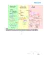
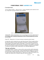
This part describes the function of the standard configuration of aSENSE VAV.
Please note that the four outputs may completely or partly have other functions.
These functions may be programmed before or after the installation. To be sure that
every unit is correctly programmed, in accordance to the actual application, a check
by a PC and the standard UIP software (version 4.3 or higher) is necessary.
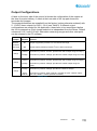
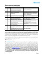
Out(1), Out(2) and Out(3) are pre-programmed alternative outputs for demand
controlled ventilation. Out(4) is intended for connection to a heat activator, if
requested.
Out(1) = control signal of demand of coolness and air
quality (with reduced flow by extreme cold)
Out(2) = control signal of demand of air quality
Out(3) = ON/OFF of demand of air quality
Out(4) = control signal of heat demand
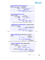
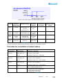
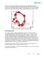
Set point values of temperature (air cooling and heating) and air quality (CO2) can
be adjusted individually by the unit’s maintenance push buttons. The different
functions with associated outputs are seen in figures 2-7. When a set point value is
changed the control curves of that parameter are parallel displaced! Out(1) controls
both air quality and temperature but temperature overrules so if the temperature
sinks below the LIMIT value the air supply is cut down. Two different gain alternatives
can be used in the temperature/cooling feed-back loop. In alternative 1 the P-band is
1 degree and in alternative 2 the P-band is 2 degrees (see figure 2). Temperature
compensation of the demand control is done for temperatures below LIMIT value
(see figure 4).
The standard configuration of aSENSE VAV, with its settings, is typical in many
Variable Air Volume (VAV) applications. Even other control parameters can be
programmed from the UIP software. There are a number of different regulator blocks
available:
6 programmable P-bands (linear functions) with associated set points, 2 additional
general purpose P-bands, plus 1 timer function regulator controlled by the DI1terminal are available. In addition, the different regulator outputs may be mixed
together using 3 multiplexer (4:1) blocks. To each of the 4 outputs 4 of the available
functions can be addressed so that the sum, or the largest value, is transformed to
an output signal. The Out(1) and Out(2) outputs can be limited within defined MIN
and MAX values. These MIN and MAX values can be set/updated from the push
button menu under operation.
*** Functional description in detailed block diagram form, installation manuals etc, are available on the Internet!
Document
Rev
Page
2 (18)