1
October 2006
User Manual and Reference
for EDOSK-2674
cetoni GmbH
Internet:
2
www.cetoni.de
Table of contents
1 Table of contents
1 Table of contents ........................................................................................................... 3
2 Installation and Testing................................................................................................. 6
2.2
Overview............................................................................................................ 6
2.3
Initial Installation Method ................................................................................... 6
2.4
RedBoot commands .......................................................................................... 8
2.5
Memory Map...................................................................................................... 9
2.6
EDOSK-2674 Tests ......................................................................................... 10
2.6.1
Running the eCos tests ................................................................................... 11
3 EDOSK-2674 Configuration Options.......................................................................... 14
3.2
Introduction ...................................................................................................... 14
3.3
H8S Architecture Configuration Options ......................................................... 15
3.3.1
H8S services.................................................................................................... 16
3.3.2
H8S build options............................................................................................. 17
3.4
H8S/2674 Variant Configuration Options ........................................................ 17
3.4.1
H8S/2674 on-chip generic clock controls ........................................................ 17
3.4.2
H8S/2674 build options ................................................................................... 18
3.5
EDOSK-2674 Platform Configuration Options ................................................ 19
3.5.1
EDOSK-2674 I/O related options .................................................................... 20
3.5.2
EDOSK-2674 Real-time clock constants......................................................... 20
3.5.3
EDOSK-2674 build options.............................................................................. 21
3.6
Serial Device Driver Configuration Options..................................................... 21
3.6.1
Generic H8S SCI driver ................................................................................... 21
3.6.2
EDOSK-2674 serial device drivers .................................................................. 21
3.7
Ethernet Device Driver Configuration Options ................................................ 23
3.7.1
SMSC LAN91CXX compatible Ethernet driver................................................ 23
3.7.2
EDOSK-2674 SMC91C96 Ethernet driver ...................................................... 24
3.8
H8S/2674 Watchdog driver Configuration Options ......................................... 24
3.9
Wallclock Device Driver Configuration Options............................................... 25
3.9.1
Wallclock device driver for Dallas 1672........................................................... 25
3.9.2
EDOSK-2674 board RTC driver ...................................................................... 25
3.10
FLASH Memory Device Driver Configuration Options .................................... 25
3.10.1
Intel StrateFLASH memory support................................................................. 25
3.10.2
EDOSK-2674 FLASH memory support ........................................................... 25
4 Realtime Characterization........................................................................................... 26
Table of contents
3
5 Porting Guide................................................................................................................28
5.2
H8S eCos Exception-/Interrupt Handling explained.........................................28
5.2.1
Hardware Vector Table ....................................................................................29
5.2.2
Shadow Vector Table.......................................................................................29
5.2.3
The Interrupt Entry Routine..............................................................................29
5.2.4
VSR Table ........................................................................................................29
5.2.5
Default Interrupt VSR .......................................................................................30
5.2.6
Interrupt Handler Table ....................................................................................30
5.2.7
User ISR...........................................................................................................30
5.2.8
Default Exception VSR.....................................................................................30
5.2.9
Exception Handler............................................................................................30
5.3
Understanding HAL Startup .............................................................................30
5.4
Variant HAL Porting to H8S/2357 ....................................................................34
5.4.1
HAL Variant Porting Process ...........................................................................34
5.4.2
HAL Variant CDL..............................................................................................34
5.4.3
Module Register Description ............................................................................36
5.4.4
Interrupt Vectors...............................................................................................37
5.4.5
Variant Startup Macros ....................................................................................37
5.4.6
The File var_misc.c ..........................................................................................38
5.5
Platform HAL Porting to Cetoni MCU2357.......................................................42
5.5.1
HAL Platform Porting Process .........................................................................42
5.5.2
HAL Platform CDL............................................................................................42
5.5.3
Platform include files ........................................................................................50
5.5.4
Platform source files.........................................................................................51
5.5.5
Memory Layout ................................................................................................53
6 Application Development ............................................................................................57
6.2
Symbolic Interrupt Vector Names ....................................................................57
6.2.1
External Interrupts............................................................................................57
6.2.2
Miscellaneous Interrupts ..................................................................................58
6.2.3
TPU - 16 Bit Timer Pulse Unit Interrupts..........................................................58
6.2.4
TMR - 8 Bit Timers ...........................................................................................59
6.2.5
DMA & EXDMA Controller Interrupts ...............................................................59
6.2.6
SCI – Serial Communication Interface Interrupts.............................................60
6.3
Interrupt Priority Levels ....................................................................................60
6.4
Interrupt Configuration .....................................................................................61
7 Configuring the Windows Host...................................................................................62
4
7.2
Installing the Cygwin Native Tools ...................................................................62
7.3
Installing H8S Cross-Development Tools ........................................................64
7.4
Installing the eCos Development Kit ................................................................65
Table of contents
8 Debugging with Insight ............................................................................................... 67
8.2
Starting Insight................................................................................................. 67
8.3
Debugging ....................................................................................................... 68
8.3.1
Debugging using serial line ............................................................................. 68
8.3.2
Debugging via Ethernet ................................................................................... 69
8.3.3
Special GDB commands ................................................................................. 69
Table of contents
5
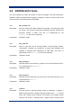
2 Installation and Testing
2.2 Overview
RedBoot uses the serial port. The default serial port settings are 115200, 8, N, 1.
Ethernet is supported using the 10-base T connector. Management of onboard flash and
onboard real-time clock is also supported.
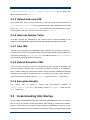
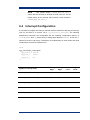
The following RedBoot configurations are supported:
Configuration
Mode
Description
File
ROM
[ROM]
RedBoot running from the
redboot_ROM.ecm
board’s main FLASH.
ROMRAM
[ROMRAM]
RedBoot
running
from
redboot_ROMRAM.ecm
SDRAM but contained in
the board’s main flash
RAM
[RAM]
RedBoot
running
from
redboot_RAM.ecm
SDRAM with RedBoot in
the main FLASH.
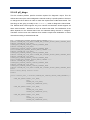
2.3 Initial Installation Method
The EDOSK-2674 board ships with the Embedded Test Suite software (ETS) in Boot
Flash (AMD) device which allows for initial programming of RedBoot.
STEP 1
Ensure that 2 jumpers are fitted to BOOT and MF_WEN headers, located behind the
Serial Connector, before applying power to the board.
STEP 2
Switch power on and press the RESET button if necessary - The Power and Boot LEDs
should be lit
STEP 4
Select “1. Flash Programming” from the Top menu. Then select “2. Main Flash (Intel)”
from the sub-menu. Answer “yes” to destroy existing Main Flash data
6
Installation and Testing
STEP 5
At this point copy the RedBoot ROM or ROMRAM SREC file to the serial port
$ cat redboot_ROM.srec > /dev/ttyS0
STEP 5
Once programming is complete, remove the BOOT and MF_WEN jumpers and press
RESET. You should now see the following RedBoot banner (can differ slightly):
Ethernet eth0: MAC address 00:00:87:d6:34:b9
IP: 192.168.0.32, Default server: 192.168.0.30
RedBoot(tm) bootstrap and debug environment [ROM]
Non-certified release, version 1.02 - built 18:45:13, Jan
2 2004
Platform: Renesas EDOSK-2674 (H8S/2674)
Copyright (C) 2000, 2001, 2002, Red Hat, Inc.
RAM: 0x00400000-0x00c00000, [0x0040af50-0x00bdd000] available
0x00ff4000-0x00ffbe00, [0x00ff4000-0x00ffbe00] available
FLASH: 0x00000000 - 0x00400000, 32 blocks of 0x00020000 bytes each.
RedBoot>
NOTE All RedBoot images were built with Ethernet support. At
startup RedBoot tries to verify the Ethernet connection. If the
board is not connected to a network, then RedBoot reports “No
network interfaces found”. If you connect to a network later the
reset the board by entering “reset” in order to allow RedBoot
network detection.
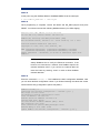
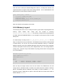
STEP 6
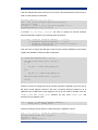
Enter the command fconfig –i. This initializes the flash configuration database. Now
you can enter all flash configuration values. If you finished entering the values the screen
should look this way (configuration options may differ):
RedBoot> fconfig -i
Initialize non-volatile configuration - continue (y/n)? y
Run script at boot: false
Use BOOTP for network configuration: false
Local IP address: 192.168.0.32
Default server IP address: 192.168.0.30
Console baud rate: 115200
Set eth0 network hardware address [MAC]: false
GDB connection port: 9000
Force console for special debug messages: false
Network debug at boot time: false
Update RedBoot non-volatile configuration - continue (y/n)? y
Installation and Testing
7
Some words about the configuration options :
Use BOOTP for network configuration
By default RedBoot tries to use BOOTP to get an IP address. If there's no
BOOTP server on your network set this option false to avoid waiting until the
timeout
Local IP address:
This IP address is the default used by RedBoot if a BOOTP/DHCP server does
not respond.
Set eth0 network hardware address [MAC]
You can force the MAC address to a desired value. If this option is false, the
MAC address will be read from the Ethernet device EEPROM.
STEP 7
Reset the board manually or by typing the reset command in order to make the
configuration options active. Now you can use your EDOSK board.
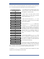
2.4 RedBoot commands
Please read the eCos reference manual for a detailed explanation of all RedBoot
commands. This paragraph covers only some commands which may be interesting for
EDOSK-2674 users.
Syntax:
Options:
Description:
date [YYYY/MM/DD HH:MM:SS]
none
Query or set the EDOSK-2674 onboard real-time clock. Provides date
and time
information
Syntax:
exec [-b <command line addr>]
[-c "kernel command line"] [<entry point>]
Options:
-b command line addr – Address in memory of Linux kernel
image
-c kernel command line – Command line to pass to Linux kernel
entry point – Starting address for Linux kernel execution
Description:
The exec command is used to execute a non-eCos application, typically
a Linux kernel. Additional information may be passed to the kernel at
startup time. This command is quite special (and unique from the go
8
Installation and Testing
command) in that the program being executed may expect certain
environmental setups. The Linux kernel expects to have been loaded to a
particular memory location which is architecture dependent. Since this
memory is used by RedBoot internally, it is not possible to load the kernel
to that location directly. Thus the requirement for the "-b" option which
tells the command where the kernel has been loaded. When the exec
command runs, the image will be relocated to the appropriate location
before being started. The "-c" option can be used to pass textual
"command line" information to the kernel. If the command line data
contains any punctuation (spaces, etc), then it must be quoted using the
double-quote character ’"’. If the quote character is required, it should be
written
as ’\"’.
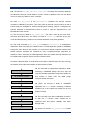
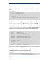
2.5 Memory Map
RedBoot sets up the following memory map on the EDOSK-2674 board. (ROM startup
with shadow vector table in RAM)
FLASH
Description
0x000000 – 0x0001ff
RedBoot ROM image
0x000200 – 0x0003ff
unused FLASH memory
RedBoot RAM data
0x000400 - 0x3fffff
0x400000 - 0x40af4f
0x40af50 – 0xBfffff
heap
Expansion board
0xc00000 – 0xdfffff
Boot Flash
0xe00000 – 0xefffff
Ethernet adapter
0xf80000 – 0xfbffff
unused On-chip RAM
0xff4000 – 0xffbaff
VSR table
0xffbb00 – 0xffbcff
Virtual Vector table
0xffbd00 – 0xffbdff
Shadow vector table
0xffbe00 – 0xffbfff
External address space
0xffc000 – 0xfffbff
Internal I/O registers
0xfffc00 – 0xfffeff
External address space
0xffff00 – 0xffff1f
Internal I/O registers
0xffff20 – 0xffffff
RAM
On-chip
Physical Address Range
Hardware vector table
SDRAM
Main
Memory
Installation and Testing
9
2.6 EDOSK-2674 Tests
The eCos repository provides test suites for various packages. The H8S architecture,
H8S/2674 variant and EDOSK-2674 platform provides a number of tests as part of the
eCos test suite. The following tests are available:
Test:
h8s_except1.cxx
Description:
This test checks basic H8S exception functionality. The test triggers trap
#0, trap #1, trap #2, trap #3 and trace exceptions and then checks if the
exception handler is called. This test is a replacement for the
except1.cxx test of eCos repository.
Provided by:
H8S/2674 variant
Test:
h8s_intr0.cxx
Description:
This is a very basic test of interrupt objects. It tests interrupt creation,
configuration, masking and unmasking. It further tests disabling and
enabling of interrupts and modification of VSR table. This test is a
replacement for the intr0.cxx test of eCos repository
Provided by:
H8S/2674 variant
Test:
h8s_kexcept1.c
Description:
This test does the same like h8s_except1.cxx but uses the Kernel API C.
It is a replacement for kexcept1.c
Provided by:
H8S/2674 variant
Test:
h8s_kintr0.cxx
Description:
This test does the same like h8s_intr0.cxx but uses the Kernel API C. It is
a replacement for kintr0.c
Provided by:
H8S/2674 variant
Test:
intnest.c
Description:
The test checks if interrupt nesting works for H8S/2674. It triggers 7
different interrupts with 7 different interrupt priorities from 1 – 7. The test
starts with lowest priority interrupt and finishes with highest priority
interrupt and checks if interrupts with a higher priority intercept lower
10
Installation and Testing
priority ISR’s. In order to execute the test, kernel should be compiled with
interrupt nesting enabled.
Provided by:
H8S/2674 variant
Test:
knmi.c
Description:
This test checks interrupt creation, configuration of NMI interrupt (rising
and falling edge) and execution of NMI ISR and DSR. This is an
interactive test and its building has to be enabled in configtool.
Provided by:
H8S/2674 variant
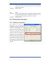
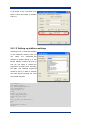
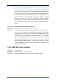
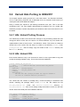
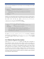
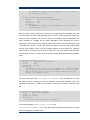
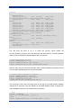
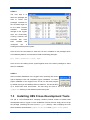
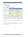
2.6.1 Running the eCos tests
2.6.1.1 Setting up connection
After
building
Configuration
the
Tool
tests,
also
the
facilitates
automatically downloading and running
the tests on the target hardware. To run
the tests using the Configuration Tool,
select Tools -> Run Tests. This brings
up the Run Tests dialog box. Prior to
running the tests, the method for
connecting to the target hardware is
selected. Clicking the Properties button
at the bottom of the Run Tests dialog
box brings up the Settings dialog box. If
you would like to use serial connection
then select Serial and setup Port and
Baudrate:
Installation and Testing
11
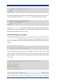
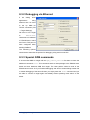
If you prefer a TCP connection then
select TCP/IP and setup IP address
and Port
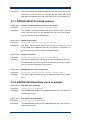
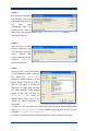
2.6.1.2 Setting up platform settings
Selecting Tools -> Platforms will bring
up the Platforms window. Here you
can
select
the
edosk2674_h8s
platform by double clicking on it. The
Modify Platform window will pop up
and you can setup or change the
arguments for GDB when executing
the tests. The following arguments
should be set up in order to execute
the tests without pressing the reset
switch after each test:
set height 0
set debug remote 0
set remoteaddresssize 32
set remotebaud %b
target remote %p
load
break cyg_test_exit
break cyg_assert_fail
break cyg_test_init
cont
set cyg_test_is_simulator=0
cont
bt
maintenance packet r
detach
12
Installation and Testing
2.6.1.3 Building the tests
Make sure that the option Asserts & Tracing in Infrastructure package is enabled when
building the eCos test cases. When building performnce tests like tm_basic.c or
dhrystons.c then Assert & Tracing schould be disabled in order to get the real
performance.
2.6.1.4 Executing the tests
After executing a test and before executing the next one the message Press OK when
target is reset – cancel to abort run will be displayed. You do not need to reset the board
manually (only required the first time GDB connects to the board) because after each test
GDB sends a reset package which will reset the board – so you simply have to click OK if
the message occurs.
Installation and Testing
13
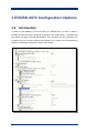
3 EDOSK-2674 Configuration Options
3.2 Introduction
In order to build RedBoot or the eCos library for EDOSK-2674 you have to select a
template and the hardware in graphical configuration tool. Select Build -> Templates and
then select the target “Renesas EDOSK2674” from Hardware list and a template from
Packet list. Now you should configure the template to your needs. For the EDOSK-2674
platform the following configuration options are available.
14
EDOSK-2674 Configuration Options
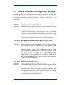
3.3 H8S Architecture Configuration Options
The H8S architecture HAL package provides generic support for the H8S CPU
architecture. It is also necessary to select a specific target platform HAL package. You
find the H8S architecture configuration options in configtool in eCos HAL -> H8S
architecture.
Option Name
Extended Interrupt Mode
CDL Name
CYGHWR_HAL_H8S_INT_CTRL_MODE_2
Description
The H8S architecture supports 2 interrupt modes: interrupt control mode
0 (normal) and interrupt control mode 2 (extended). Interrupt operations
differ depending on the interrupt control mode. In interrupt control mode
0, interrupt requests except for NMI are masked by the I-bit of CCR. In
interrupt control mode 2, mask control is done in eight levels for interrupt
requests except for NMI by comparing the EXR interrupt mask level (I2 to
I0 bits) and the IPR settings. At the moment only ICM2 is supported
Option Name
Save Multiply-Accumulate Register (MAC) on context switch
CDL Name
CYGHWR_HAL_H8S_USE_MAC
Description
On the H8S/2600 CPU this 64-bit register stores the results of multiplyand-accumulate operations. It consists of two 32-bit registers denoted
MACH and MACL. The lower 10 bits of MACH are valid; the upper bits
are a sign extension. If this option is disabled then the MAC registers
won’t be safe when switching tasks or on interrupt occurrence. This will
save some time but the content will not be available for GDB.
IMPORTANT!!! - If you would like to debug applications where you use
MAC than RedBoot also have to be build with MAC support because it
contains the whole debugging code.
Option Name
Position of shadow vector table.
CDL Name
CYGBLD_HAL_H8S_SHADOW_VECTOR_TABLE_POS
Description
For interrupt handling the H8S architecture needs an additional shadow
vector table of 512 bytes. This option chooses if this table should be
placed into RAM or ROM. If a ROM monitor is built then the RAM location
is the preferred place in order to allow RAM applications to use or change
this table. For a final ROM application a ROM location of this table would
be better because this saves RAM memory.
EDOSK-2674 Configuration Options
15
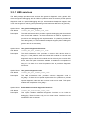
3.3.1 H8S services
The H8S package provides some services like generich diagnostic code, generic SCI
driver and generic debugging stub for GDB. If a platform does not need to provide special
diagnostic code or a special debugging stub (i.e. with hardware breakpoint support, then
it can use the generic code by just implementing some interfaces defined in hal_h8s.cdl)
Option Name
Use generic debugging stub
CDL Name
CYGBLD_HAL_H8S_COMMON_GDB_STUB
Description
The H8S architecture HAL provides a generic debugging stub that should
work for all H8S variants - So there should be no need for a platform to
provide its own debugging stub implementation. If a platform provides an
own debug stub (i.e. with hardware breakpoint support) then building this
generic stub is not necessary.
Option Name
Use generic diagnostic SCI driver
CDL Name
CYGBLD_HAL_H8S_COMMON_SCI_CODE
Description
The H8S architecture HAL provides a common SCI device driver in
h8s_sci.c. If the platform uses the internal SCI module for console and
diagnostic output, and the SCI module can be driven by the common SCI
driver, then this option should be enabled. It enables the compilation of
h8s_sci.c. So there is no need for platform HAL to provide a diagnostic
SCI driver.
Option Name
Use generic diagnostic code
CDL Name
CYGBLD_HAL_H8S_COMMON_DIAG_CODE
Description
The H8S architecture HAL provides common diagnostic code in
hal_diag.c. If there are no special requirements for a platform to provide
special diagnostic code then this common code can be used. This option
enables the compilation of hal_diag.c
Option Name
Build additional serial diagnostic functions
CDL Name
CYGBLD_HAL_ADDITIONAL_DIAG_CODE
Description
This option enables additional diagnostic functions to be build for
debugging. These functions rely not on virtual vector interface but are
hardwired to SCI 2 channel.
16
EDOSK-2674 Configuration Options
3.3.2 H8S build options
Option Name
Linker script
CDL Name
CYGBLD_LINKER_SCRIPT
Description
Linker script required for build process.
3.4 H8S/2674 Variant Configuration Options
The H8S/2674 variant HAL package provides generic support for the H8S/2674
processor. It is also necessary to select a specific target platform HAL package. You find
the H8S/2674 variant configuration options in configtool in eCos HAL -> H8S architecture
-> H8S/2674 variant.
Option Name
Watchdog module mask, unmask, ackn. support
CDL Name
CYGBLD_HAL_H8S_WATCHDOG_INTERRUPT_CODE
Description
Watchdog module interrupt mask, unmask and acknowledge differs from
other
H8S/2674
modules.
In
cyg_interrupt_mask,
order
to
support
the
cyg_interrupt_unmask
function
and
cyg_interrupt_acknowledge for the watchdog module (also if you use it as
a simple overflow timer), additional code is necessary that is executed
every time one of the functions above is called. If you don't need the
module or if you use the eCos H8S/2674 watchdog driver then you do not
need this extra code. This will save some time in ISR's and decrease
code size a little bit.
3.4.1 H8S/2674 on-chip generic clock controls
Option Name
PLL Multiplier Rate (Nx)
CDL Name
CYGHWR_HAL_H8S_MULT_RATE
Description
The PLL circuit has the function of multiplying the frequency of the clock
from the oscillator by a factor of 1, 2, or 4.
Option Name
Clock Divider Rate (1/n)
CDL Name
CYGHWR_HAL_H8S_DIVIDER_RATE
Description
The frequency divider divides the PLL output clock to generate a 1/2, 1/4,
1/8, 1/16, or 1/32 clock. The following points should be noted since the
frequency of clock changes according to the setting of Clock Divider Rate
and PLL Multiplier Rate. Select the clock division ratio that is within the
operation guaranteed range of clock cycle time tcyc shown in the AC
EDOSK-2674 Configuration Options
17
timing of Electrical Characteristics. In other words, the range of clock
must be specified from 8 MHz (min) to 33 MHz (max). Outside of this
range must be prevented. All the on-chip peripheral modules operate on
the clock. Therefore, note that the time processing of modules such as a
timer and SCI differ before and after changing the clock division ratio. In
addition, wait time for clearing software standby mode differs by changing
the clock division ratio. See the description, Setting Oscillation
Stabilization Time after Clearing Software Standby Mode in section
22.2.3, Software Standby Mode, of the H8S2674 hardware manual for
details.
Option Name
Internal clock to peripheral modules (Hz)
CDL Name
CYGHWR_HAL_H8S_INTERNAL_MODULE_CLOCK
Description
The on chip peripheral modules operate on the system clock. The system
clock (core CPU speed) is computed from the input clock speed,
(OSC/Clock Frequency in platform hal) the PLL Multiplier Rate and the
Divider Rate. (Core CPU speed = OSC/Clock Frequency * PLL Multiplier
Rate / Divider Rate). Select the clock division ratio that is within the
operation guaranteed range of clock cycle time tcyc shown in the AC
timing of Electrical Characteristics. In other words, the range of clock
must be specified from 8 MHz (min) to 33 MHz (max). Outside of this
range must be prevented.
3.4.2 H8S/2674 build options
Option Name
H8S/2674 tests
CDL Name
CYGPKG_HAL_H8S_H8S2674_TESTS
Description
This option specifies the set of tests for the H8S/2674 variant.
18
EDOSK-2674 Configuration Options
3.5 EDOSK-2674 Platform Configuration
Options
The EDOSK-2674 HAL package provides the support needed to run eCos on an
Evaluation Design O/S Kit for H8S/2674. You find the EDOSK-2674 platform
configuration options in configtool in eCos HAL -> H8S architecture -> EDOSK-2674
platform.
Option Name
Startup type
CDL Name
CYG_HAL_STARTUP
Description
When targeting the EDOSK-2674 board, it is possible to build the system
for RAM, ROM or ROMRAM bootstrap. RAM bootstrap generally requires
that the boards main FLASH contains a suitable ROM monitor software
(preferably RedBoot) that allows GDB to download the eCos application
into RAM. The ROM and ROMRAM bootstrap typically requires that the
eCos application be blown into the board’s main FLASH. ROMRAM
startup requires extra RAM memory because the complete image will be
copied from ROM into RAM before startup. RAMAPP is a special RAM
startup. This startup is required if a RedBoot RAM image is running on
the board and an application should be debugged with this image.
Because RedBoot already resides in RAM, the application has to be
loaded behind the RedBoot image in RAM. This is required if i.e.
debugging of the GDB stub inside the RedBoot RAM image is necessary.
Option Name
Memory Layout
CDL Name
CYGHWR_MEMORY_LAYOUT
Description
This is the memory layout used for building. It is selected according to the
startup (RAM, ROM, ROMRAM; RAMAPP) settings.
Option Name
OSC/Clock Frequency
CDL Name
CYGHWR_HAL_H8S_CPG_INPUT
Description
The MCU crystal frequency has been chosen to support the fastest
operation. The value of the crystal is 33 MHz.
Option Name
Build interactive tests
CDL Name
CYGPKG_HAL_H8S_H8S2674_EDOSK2674_INTERACTIVE_TEST
EDOSK-2674 Configuration Options
19
Description
This option enables the building of EDOSK-2674 tests which require user
interactivity in order to pass. (For example the NMI switch test) These
tests are built separately since they only make sense to use interactively.
3.5.1 EDOSK-2674 I/O related options
Option Name
Number of communication channels on the board
CDL Name
CYGNUM_HAL_VIRTUAL_VECTOR_COMM_CHANNELS
Description
The H8S/2674 has three independent serial communication channels
(SCI0, SCI1 and SCI2). On the EDOSK board only one serial channel,
SCI2 is connected to an RS-232 interface.
Option Name
Debug serial channel
CDL Name
CYGNUM_HAL_VIRTUAL_VECTOR_DEBUG_CHANNEL
Description
This option chooses which channel will be used to connect to a host
running GDB. On the EDOSK board only one channel is connected to an
RS-232 interface and can be used for debugging (SCI2).
Option Name
Diagnostic Channel
CDL Name
CYGNUM_HAL_VIRTUAL_VECTOR_CONSOLE_CHANNEL
Description
This option chooses which channel will be used for diagnostic output. On
the EDOSK board only one channel is connected to an RS-232 interface
and can be used for diagnostic output (SCI2).
Option Name
GDB/Diagnostic serial port baud rate
CDL Name
CYGNUM_HAL_VIRTUAL_VECTOR_CONSOLE_CHANNEL_BAUD
Description
This option selects the baud rate for the diagnostic/debug serial channel
SCI 2.
3.5.2 EDOSK-2674 Real-time clock constants
Option Name
Real-time clock numerator
CDL Name
CYGNUM_HAL_RTC_NUMERATOR
Description
The NUMERATOR divided by the DENOMINATOR gives the number of
nanoseconds per tick.
Option Name
Real-time clock denominator
CDL Name
CYGNUM_HAL_RTC_DENOMINATOR
Description
The NUMERATOR divided by the DENOMINATOR gives the number of
nanoseconds per tick.
20
EDOSK-2674 Configuration Options
Option Name
Real-time clock period
CDL Name
CYGNUM_HAL_RTC_PERIOD
Description
The PERIOD is the divider to be programmed into a hardware timer that
is driven from an appropriate hardware clock, such that the timer
overflows once per tick. The EDOSK board uses the TPU channel 5 as
hardware timer.
Option Name
Real-time clock frequency
CDL Name
CYGNUM_HAL_RTC_FREQUENCY
Description
This is the frequency of the real-time clock. This is the clock source for
the eCos operating system. The frequency is calculated from numerator
and denominator.
3.5.3 EDOSK-2674 build options
Option Name
EDOSK-2674 tests
CDL Name
CYGPKG_HAL_ H8S_H8S2674_EDOSK2674_TESTS
Description
This option specifies the set of tests for the EDOSK-2674 platform.
3.6 Serial Device Driver Configuration
Options
3.6.1 Generic H8S SCI driver
This option enables the generic serial device driver for the SCI module in Hitachi H8S
CPUs.
No configuration options available.
3.6.2 EDOSK-2674 serial device drivers
This option enables the serial device drivers for the EDOSK-2674 board, based on the
generic H8S SCI driver.
Option Name
SCI2 serial device driver
CDL Name
CYGPKG_IO_SERIAL_H8S_EDOSK2674_SERIAL2
Description
This option includes the serial device driver for the SCI 2 port. The SCI 2
port is the only SCI port which is connected to a RS232 interface on the
board.
EDOSK-2674 Configuration Options
21
Option Name
Device Name
CDL Name
CYGDAT_IO_SERIAL_H8S_EDOSK2674_SERIAL2_NAME
Description
This option specifies the device name for the SCI 2 port.
Option Name
Baud Rate
CDL Name
CYGDAT_IO_SERIAL_H8S_EDOSK2674_SERIAL2_BAUD
Description
This option specifies the default baud rate (speed) for the SCI port 2. The
EDOSK-2674 port is to slow for baud rates higher than 14400 baud when
using interrupt driven mode.
Option Name
Interrupt priority
CDL Name
CYGDAT_IO_SERIAL_H8S_EDOSK2674_SERIAL2_INT_PRIO
Description
This option specifies the priority of all SCI 2 interrupts (ERI2, RXI2, TXI2
and TEI2). The lowest priority is 0 and the highest priority is 7. By default
(reset) all H8S/2674 interrupt priorities are initialized to priority level 7.
Option Name
Receiver is interrupt driven
CDL Name
CYGDAT_IO_SERIAL_H8S_EDOSK2674_SERIAL2_RX_INTDRV
Description
This option enables interrupt controlled receiver. If this option is turned off
only simple serial polling driver is available for receiver. The EDOSK
board provides only one serial channel. This channel is also used for
debugging with GDB. In order to use interrupts the CTRL C and break
support for GDB have to be turned off because they use the same
interrupt vector like this serial driver
Option Name
Buffer size for receiver
CDL Name
CYGDAT_IO_SERIAL_H8S_EDOSK2674_SERIAL2_RX_BUFSIZE
Description
This option specifies the size of the internal receive buffer used for the
SCI port 2. A receive buffer is only required in interrupt driven mode.
Option Name
Transmitter is interrupt driven
CDL Name
CYGDAT_IO_SERIAL_H8S_EDOSK2674_SERIAL2_TX_INTDRV
Description
This option enables interrupt controlled transmitter. If this option is turned
off only simple serial polling driver is available for transmitter. The
EDOSK board provides only one serial channel. This channel is also
used for debugging with GDB. In order to use interrupts the CTRL C and
break support for GDB have to be turned of because they use the same
interrupt vector like this serial driver
22
EDOSK-2674 Configuration Options
Option Name
Buffer size for receiver
CDL Name
CYGDAT_IO_SERIAL_H8S_EDOSK2674_SERIAL2_TX_BUFSIZE
Description
This option specifies the size of the internal transmit buffer used for the
SCI port 2. A transmit buffer is only required in interrupt driven mode.
Option Name
Testing parameters
CDL Name
CYGDAT_IO_SERIAL_H8S_EDOSK2674_TESTING
Description
This option defines various parameters required for running the serial
tests.
3.7 Ethernet Device Driver Configuration
Options
3.7.1 SMSC LAN91CXX compatible Ethernet driver
Ethernet driver for SMSC LAN91CXX compatible controllers
Option Name
SIOCSIFHWADDR records ESA (MAC address) in EEPROM
CDL Name
CYGSEM_DEVS_ETH_SMSC_LAN91CXX_WRITE_EEPROM
Description
The ioctl() socket call with operand SIOCSIFHWADDR sets the interface
hardware address - the MAC address or Ethernet Station Address (ESA).
This option causes the new MAC address to be written into the EEPROM
associated with the interface, so that the new MAC address is
permanently recorded. Doing this should be a carefully chosen decision,
hence this option.
Option Name
Interrupt priority when registering interrupt handler
CDL Name
CYGNUM_DEVS_ETH_SMSC_LAN91CXX_INT_PRIO
Description
When registering the interrupt handler this specifies the priority of the
interrupt. Some hardware platforms require values other than the default
given here. Such platforms can then override this value in the hardware
specific package.
EDOSK-2674 Configuration Options
23
3.7.2 EDOSK-2674 SMC91C96 Ethernet driver
Ethernet driver for EDOSK-2674 boards
Option Name
EDOSK-2674 Ethernet port driver
CDL Name
CYGDAT_DEVS_ETH_H8S_EDOSK2674_ETH0
Description
This option includes the ethernet device driver for the EDOSK-2674 port.
Option Name
Device name for the ethernet driver
CDL Name
CYGDAT_DEVS_ETH_H8S_EDOSK2674_ETH0_NAME
Description
This option sets the name of the ethernet device for the ethernet port.
Option Name
Set the ethernet station address
CDL Name
CYGDAT_DEVS_ETH_H8S_EDOSK2674_ETH0_SET_ESA
Description
Enabling this option will allow the ethernet station address to be forced to
the value set by the configuration. This may be required if the hardware
does not include a serial EEPROM for the ESA. The EDOSK-2674 board
contains an EEPROM so setting the ESA here is not required
Option Name
Set the ethernet station address
CDL Name
CYGDAT_DEVS_ETH_H8S_EDOSK2674_ETH0_ESA
Description
A static ethernet station address. Caution: Booting two systems with the
same MAC on the same network will cause severe conflicts.
3.8 H8S/2674 Watchdog driver Configuration
Options
Option Name
Watchdog input clock divider rate (Processor Clock/n)
CDL Name
CYGNUM_DEVS_WATCHDOG_H8S_H8S2674_DIVIDER_RATE
Description
Selects the clock source to be input to watchdog timer. The clock is
calculated from the H8S/2674 processor speed and this clock divider.
Option Name
Watchdog timer overflow period in ns
CDL Name
CYGNUM_DEVS_WATCHDOG_H8S_H8S2674_PERIOD
Description
The rough calculated time interval in nanoseconds allowed between
resets before watchdog triggers. The interval depends on the divider rate
for the watchdog clock source.
24
EDOSK-2674 Configuration Options
3.9 Wallclock Device Driver Configuration
Options
3.9.1 Wallclock device driver for Dallas 1672
This package provides a file with init, get and set functions for the Dallas 1672 clock part.
No configuration options available.
3.9.2 EDOSK-2674 board RTC driver
RTC driver for EDOSK2674 board
No configuration options available.
3.10 FLASH Memory Device Driver
Configuration Options
3.10.1
Intel StrateFLASH memory support
FLASH memory device support for Intel StrataFlash
No configuration options available.
3.10.2
EDOSK-2674 FLASH memory support
FLASH memory device support for MAIN Flash memory (INTEL 28F320J3A) on EDOSK2674 board
No configuration options available.
EDOSK-2674 Configuration Options
25
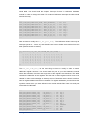
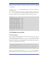
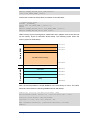
4 Realtime Characterization
This is the result of the tm_basic.c test from eCos test suite. The test was built and
executed with assertions disabled in order to get the real performance of a final
application:
Board: Renesas EDOSK-2674
CPU: Renesas H8S/2674
Startup, main stack
Startup
Startup
: stack used
: Interrupt stack used
: Idlethread stack used
74 size
115 size
40 size
2048
4096
2048
eCos Kernel Timings
Notes: all times are in microseconds (.000001) unless otherwise stated
Reading the hardware clock takes 10 'ticks' overhead
... this value will be factored out of all other measurements
Clock interrupt took 111.72 microseconds (230 raw clock ticks)
Testing parameters:
Clock samples:
Threads:
Thread switches:
Mutexes:
Mailboxes:
Semaphores:
Scheduler operations:
Counters:
Flags:
Alarms:
32
64
128
32
32
32
128
32
32
32
Confidence
Var Ave Min Function
====== ========== ========
18.05
50%
25% Create thread
0.00 100% 100% Yield thread [all suspended]
0.17
76%
23% Suspend [suspended] thread
0.24 100%
50% Resume thread
0.24
54%
54% Set priority
0.24
54%
45% Get priority
0.15
81%
18% Kill [suspended] thread
0.24
51%
51% Yield [no other] thread
0.12
98%
98% Resume [suspended low prio] thread
0.08
89%
1% Resume [runnable low prio] thread
0.27
98%
51% Suspend [runnable] thread
0.07
92%
92% Yield [only low prio] thread
0.20
70%
29% Suspend [runnable->not runnable]
0.00 100% 100% Kill [runnable] thread
0.11
84%
12% Destroy [dead] thread
0.26
67%
9% Destroy [runnable] thread
0.63
98%
98% Resume [high priority] thread
0.17
76%
0% Thread switch
Ave
======
132.92
21.33
20.25
20.61
35.13
3.17
84.27
21.57
41.27
19.92
33.23
21.37
20.22
83.39
50.38
105.33
132.36
50.81
Min
======
96.97
21.33
19.88
20.36
34.91
2.91
83.88
21.33
41.21
19.39
32.97
21.33
19.88
83.39
49.94
104.73
131.88
49.94
Max
======
168.73
21.33
20.36
20.85
35.39
3.39
84.36
21.82
45.09
20.36
35.39
21.82
20.36
83.39
50.91
108.61
152.24
51.39
2.32
12.62
12.62
12.59
12.63
1.94
12.61
12.61
12.12
12.61
2.42
13.09
13.09
13.09
13.09
0.16
0.03
0.04
0.05
0.04
78%
96%
96%
92%
95%
21%
96%
96%
5%
95%
Scheduler
Scheduler
Scheduler
Scheduler
Scheduler
5.92
25.06
33.89
22.51
18.23
4.68
5.82
24.73
33.45
22.30
17.94
4.36
6.30
25.21
34.91
22.79
18.42
4.85
0.17
0.21
0.16
0.24
0.23
0.22
78%
68%
75%
56%
59%
65%
78%
31%
18%
56%
40%
34%
Init mutex
Lock [unlocked] mutex
Unlock [locked] mutex
Trylock [unlocked] mutex
Trylock [locked] mutex
Destroy mutex
26
lock
unlock
unlock
unlock
unlock
[0 threads]
[1 suspended]
[many suspended]
[many low prio]
Realtime Characterization
177.59
176.97
177.94
0.22
65%
3%
Unlock/Lock mutex
11.11
2.47
28.55
2.45
28.58
2.45
28.33
28.33
25.95
23.89
31.21
21.76
21.70
3.30
3.18
28.51
95.15
10.67
1.94
28.12
1.94
28.12
1.94
28.12
28.12
25.70
23.76
31.03
21.33
21.33
2.91
2.91
28.12
94.55
11.15
2.91
29.09
2.91
29.09
2.91
28.61
28.61
26.18
24.24
31.52
22.30
22.30
3.39
3.39
28.61
95.52
0.08
0.19
0.13
0.23
0.09
0.14
0.24
0.24
0.24
0.20
0.23
0.13
0.20
0.15
0.24
0.15
0.23
90%
65%
81%
56%
87%
75%
56%
56%
53%
71%
62%
81%
68%
81%
56%
81%
62%
9%
12%
15%
18%
9%
9%
56%
56%
46%
71%
62%
15%
28%
18%
43%
18%
6%
Create mbox
Peek [empty] mbox
Put [first] mbox
Peek [1 msg] mbox
Put [second] mbox
Peek [2 msgs] mbox
Get [first] mbox
Get [second] mbox
Tryput [first] mbox
Peek item [non-empty] mbox
Tryget [non-empty] mbox
Peek item [empty] mbox
Tryget [empty] mbox
Waiting to get mbox
Waiting to put mbox
Delete mbox
Put/Get mbox
4.76
19.06
21.73
17.85
18.21
5.79
4.23
99.24
4.36
18.91
21.33
17.45
17.94
5.33
3.88
98.91
4.85
19.39
21.82
17.94
18.42
6.30
4.36
99.39
0.15
0.21
0.15
0.15
0.24
0.09
0.20
0.21
81%
68%
81%
81%
56%
87%
71%
68%
18%
68%
18%
18%
43%
9%
28%
31%
Init semaphore
Post [0] semaphore
Wait [1] semaphore
Trywait [0] semaphore
Trywait [1] semaphore
Peek semaphore
Destroy semaphore
Post/Wait semaphore
8.82
5.83
5.20
32.73
4.82
8.73
5.82
4.85
32.48
4.36
9.21
6.30
5.33
32.97
5.33
0.15
0.03
0.20
0.24
0.11
81%
96%
71%
100%
81%
81%
96%
28%
50%
12%
Create counter
Get counter value
Set counter value
Tick counter
Delete counter
4.76
19.41
17.00
20.89
32.50
32.24
33.09
32.82
1.42
4.36
19.39
16.48
20.85
32.00
32.00
32.97
32.48
0.97
4.85
19.88
17.45
21.33
32.97
32.48
33.45
32.97
1.94
0.15
0.03
0.08
0.08
0.09
0.24
0.18
0.21
0.14
81%
96%
87%
90%
84%
100%
75%
68%
75%
18%
96%
3%
90%
6%
50%
75%
31%
15%
Init flag
Destroy flag
Mask bits in flag
Set bits in flag [no waiters]
Wait for flag [AND]
Wait for flag [OR]
Wait for flag [AND/CLR]
Wait for flag [OR/CLR]
Peek on flag
16.23
16.00
16.48
47.71
47.52
48.00
17.09
16.97
17.45
40.36
40.24
40.73
21.15
20.85
21.33
39.94
39.76
40.24
285.52 282.67 370.42
74.35
74.18
74.67
1606.42 1591.27 1689.21
326.53 323.39 411.15
98.84
97.94 161.45
110.97
97.94 161.45
114.61
97.94 165.33
213.20 201.70 530.42
0.24
0.23
0.18
0.18
0.23
0.23
5.31
0.22
24.05
5.29
0.99
10.43
10.84
4.96
53%
59%
75%
75%
62%
62%
96%
65%
84%
96%
99%
50%
46%
98%
53%
59%
75%
75%
37%
62%
96%
65%
84%
96%
99%
54%
31%
0%
Create alarm
Initialize alarm
Disable alarm
Enable alarm
Delete alarm
Tick counter [1 alarm]
Tick counter [many alarms]
Tick & fire counter [1 alarm]
Tick & fire counters [>1 together]
Tick & fire counters [>1 separately]
Alarm latency [0 threads]
Alarm latency [2 threads]
Alarm latency [many threads]
Alarm -> thread resume latency
19
0
145 (main stack:
943) Thread
All done, main stack
: stack used
943
All done
: Interrupt stack used
159
All done
: Idlethread stack used
133
Timing complete - 29160 ms total
PASS:<Basic timing OK>
EXIT:<done>
Realtime Characterization
27
stack
size
size
size
used (956 total)
2048
4096
2048
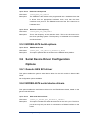
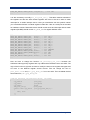
5 Porting Guide
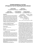
5.2 H8S eCos Exception-/Interrupt Handling
explained
1. Hardware vect. tbl
000
001
002
003
004
...
__start
__start
shadow vector 002
shadow vector 003
shadow vector 004
...
127 shadow vector 127
2. Shadow vector table
000
001
002
003
004
...
jsr
jsr
jsr
jsr
jsr
...
@interrupt_entry
@interrupt_entry
@interrupt_entry
@interrupt_entry
@interrupt_entry
127 jsr @interrupt_entry
3. interrupt_entry
4. VSR table
000
001
002
...
015
016
...
127
__default_exception_vsr
__default_exception_vsr
__default_exception_vsr
...
__default_interrupt_vsr
__default_interrupt_vsr
...
__default_interrupt_vsr
5.__default_interrupt_vsr
Decodes the actual interrupt
being delivered and invokes
the appropriate ISR
This is the trampoline code
that saves the complete
interrupt state and then
calls the vector service
routine from the VSR table.
8.__default_exception_vsr
CPU state is already saved
– simply calls
cyg_hal_exception_handler
6. hal_interrupt_handlers
000
001
002
...
127
isr
isr
isr
...
isr
0
1
2
cyg_hal_exception_handler
Does further exception
processing.
127
7. user ISR
Does further interrupt
processing
28
Porting Guide
5.2.1 Hardware Vector Table
Different vector addresses are assigned to different exception/interrupt sources. The
hardware exception vector table contains 128 vector addresses for 128 different
exception/interrupt sources of H8S architecture. The table’s base address is 0x00 and the
size of each entry is 4 byte. (the table ranges from 0x0 – 0x200). The size of this table is
4 x 128 bytes = 512 bytes.
The first two entries are the reset vectors (hardware reset and manual reset) and point to
the entry point “__start”. This is the beginning of startup code where execution begins
after reset.
All other entries point to appropriate entries within the shadow vector table. When an
exception/interrupt occurs, the PC is loaded with the appropriate shadow vector address
and execution continues there.
5.2.2 Shadow Vector Table
The shadow vector table contains 128 shadow exception/interrupt vectors. Each shadow
vector belongs to an appropriate vector in the hardware vector table. Each shadow vector
table entry contains one instruction: a jsr instruction. This jsr instruction jumps to
interrupt_entry routine. The position of the shadow vector table is configurable. It
can reside in ROM or RAM. If it resides in ROM then its base address is 0x200 and if it
resides in RAM its base address is 0xffbe00 (ranges from 0xffbe00 – 0xffc000)
The shadow vector table is required because it is the only possibility to calculate the
interrupt vector number required for addressing the vector service routines within the
VSR. Both vector tables can be found in the file vectors.S under the arch subdirectory.
5.2.3 The Interrupt Entry Routine
The interrupt_entry routine (in file vectors.S) is some kind of trampoline code
that saves all registers and then calls the appropriate vector service routine from VSR
table.
5.2.4 VSR Table
The Vector Service Routine (VSR) table is an array of pointers to the default exception
and interrupt handler routines located at a fixed memory location. The size of this table is
128 x 4 = 512 bytes. It is always located in RAM and its base address is specified in
platforms CDL file. (CYGHWR_HAL_VSR_TABLE). For the EDOSK platform the actual
address is 0xffbb00. This allows RAM applications to take control over certain exception
service
routines.
Porting Guide
Depending
on
the
occurred
interrupt/exception
29
__default_interrupt_vsr or __default_exception_vsr will be called. This
table is defined in the file vectors.S.
5.2.5 Default Interrupt VSR
This routine does some stuff like switching to interrupt stack and incrementing the
cyg_scheduler_sched_lock kernel variable to ensure that scheduling does not take
place. The __default_interrupt_vsr then needs to find out what Interrupt Service
Routine (ISR) to call. This VSR can be found in the file vectors.S.
5.2.6 Interrupt Handler Table
This table contains the addresses of the interrupt service routines installed by the
application. The default interrupt VSR calls the appropriate user ISR from this table.
5.2.7 User ISR
The ISR, which executes at the application level, performs any necessary functions for
the particular interrupt. The ISR then notifies the kernel that the DSR should be posted for
execution by returnings CYG_ISR_CALL_DSR. The ISR also returns CYG_ISR_HANDLED
to terminate any chained interrupt processing.
5.2.8 Default Exception VSR
If a synchronous exception occurs then the default exception VSR will be executed. The
job of this default exception VSR is to perform common processing of all exceptions,
which includes calling any kernel-level handler routine to perform additional processing
and restoring the state of the processor prior to returning to normal program execution.
The default exception VSR is in the file vectors.S under the HAL arch subdirectory.
5.2.9 Exception Handler
The
routine
that
is
called
to
handle
the
HAL-to-kernel
transition
is
cyg_hal_exception_handler. This routine is found in hal_misc.c under the HAL
arch subdirectory.
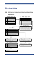
5.3 Understanding HAL Startup
To get a better understanding of the H8S, H8S/2674 and EDOSK-2674 HAL, we need to
take a look at the startup process the software goes through to initialize the hardware.
Below is a Flowchart of the routines involved during the initializations of the HAL for the
Renesas EDOSK-2674 board. In addition, note that the startup procedure might deviate
30
Porting Guide
from what is shown in the flowchart depending on the configuration options selected for
HAL. The routines described are implemented in either assembly language or C.
1. Hardware Powerup
2. reset_vector
1. The starting point for the system startup is after
a power cycle has occured. This startup process
also applies for a soft reset startup
2. After a hard or soft reset occures, the H8S
3. __start
processor jumps to its reset vector. The reset
vector is found in the file vectors.S.
4. hal_cpu_init
3. Next, the reset vector jumps to __start. This
5. hal_memc_init
is also found in vectors.S and the main starting
point for HAL initilization.
6. Setup stack pointer
4. Next, the macro hal_cpu_init is called, witch
7. hal_diag_init
is located in arch.inc. It handles setting of CCR
and EXR (masks all interrupts), to ensure that the
8. hal_mmu_init
processor is in known state for the remainder of
the initilization process. This macro, and also the
9. hal_cache_init
following macros, are conditionally defined. So
they can be overwritten by variant or platform
10. hal_intc_init
11. hal_timer_init
HALs.
5. The next macro called is hal_memc_init. This
macro is responsible for initializing memory and
12. hal_mon_init
bus controller of EDOSK board. After execution of
this macro it is possible to access internal and
13. Setup shadow vect. tbl.
14.Copy rom image into ram
external RAM and ROM safely.
6. Now that it is safe to access RAM memory, the
stack pointer is initialized to point to the interrupt
stack. This stack is always present and large enough to handle startup function calls.
Now it is possible to call C functions because a valid stack pointer is set up.
7. The macro hal_diag_init is empty at the moment. Here it is possible for a variant
or platform HAL to setup diagnostic stuff like LEDs.
Porting Guide
31
8./9. The macros hal_mmu_init, hal_cache_init are empty at the moment because
the H8S/2674 does not contain MMU or caches. Variant or platform HALs can use these
macros to setup any MMU or cache controller.
10. Next hal_intc_init in file platform.inc initializes the internal interrupt
controller of H8S/2674 processor. This macro sets up interrupt control mode 2 so that 8
priority levels are available for interrupt handling and masking. Further it configures the
external interrupts of EDOSK-2674 board in order to fulfil the requirements in the
EDOSK-2674 user manual.
11. The next macro called is hal_timer_init. This macro sets up the clock which
drives the eCos RTC later. The macro is located in varint.inc and sets up the PLL
circuit and the frequency divider for the internal H8S/2674 clock pulse generator.
12. The code executed in hal_mon_init, located in variant.inc is configuration
dependent. When executing as a ROM monitor or ROM application (ROM or ROMRAM
startup) the main task for this routines is to ensure that default exception handlers and
default interrupt handlers are installed for every exception/interrupt supported by
H8S/2674. When executing as RAM application then only default interrupt handlers will
be installed and exception vectors remains to ROM monitor.
13. When a RAM location of the shadow vector table is selected then this step will copy
the shadow vector table from ROM to its final location in RAM.
14. The next step is configuration dependent. When
15. setup data section
executing a ROMRAM startup then this step will
copy the complete application image from ROM to its
16. clear bss section
final location in RAM. Then the RAM image
continues startup execution.
17. hal_variant_init
15. When we execute a ROM or ROMRAM
18. hal_platform_init
application the data section containing initialized
variables has to be copied from ROM into its final
19. initialize_stub
20. hal_ctrlc_isr_init
position in RAM.
16. The next step in the HAL initialization process is
to clear the bss section, which contains all no
21. Invoke constructors
initialized local and global variables with static
storage class.
22. cyg_start
17. Next the C function hal_varint_init located
32
Porting Guide
in file var_misc.c is called in order to give the variant HAL the possibility of executing
complex variant specific initialisation code that cannot be done in assembly code.
17. Next the C function hal_varint_init located in file var_misc.c is called in order
to give the variant HAL the possibility of executing complex variant specific initialisation
code that cannot be in assembly code.
18. Next, the C routine hal_platformm_init is called located in plf_misc.c. This, in
turn calls hal_if_init, found in file hal_if.c of the HAL common subdirectory. The
routine hal_if_init initializes the virtual vector table based on configuration options
selected.
19. If the configuration is set up for a debug environment and a ROM monitor is not
providing debug support, the next routine called is initialize_stub, located in the
HAL common subdirectory in the file generic_stub.c. The routine initializes the
hardware for debug.
20. If CTRL C support is selected for debugging, then hal_ctrlc_isr_init is called
next, which installs the SCI 2 ISR for handling CTRL C requests.
21.
Next,
all
global
C++
constructors
are
called
from
cyg_hal_invoke_constructors. This routine is in the file hal_misc.c under the
arch subdirectory.
22. Finally, the last step in the HAL initialization process is to turn control over to the
kernel for its initialization. The routine cyg_start is the playe for HAL-to-kernel
transition.
Porting Guide
33
5.4 Variant HAL Porting to H8S/2357
This chapter explains porting process for a new H8S variant - the Renesas H8S/2357.
This is a H8S family processor with a H8S/2000 CPU core internal FLASH memory of
128 Kbytes and internal RAM of 8 KBytes..
Doing a variant port requires a pre-existing architecture HAL port. This is the H8S
architecture HAL. The next chapter demonstrates the platform port for a board with
H8S/2357 processor. Variant and platform port should be done at the same time if it is to
be tested.
5.4.1 HAL Variant Porting Process
The easiest way to make a new variant HAL is simply to copy an existing variant HAL and
change the files to match the new variant. For H8S architecture only one variant HAL
implementation exists at the moment – the H8S/2674 variant. This will be our reference
variant HAL to be copied. The first step is to create a new directory h8s2357 under
packages/hal/h8s. Next we simply copy the content of the h8s2674 directory into
the h8s2357 directory.
5.4.2 HAL Variant CDL
Each variant needs an entry in the ecos.db file. Here it is also a good idea to copy and
modify the existing H8S/2674 entry. This is the one for the H8S/2357:
package CYGPKG_HAL_H8S_H8S2357 {
alias
{ "Hitachi H8S/2357 variant HAL" hal_h8s2357
h8s2357_hal}
directory
hal/h8s/h8s2357
script
hal_h8s_h8s2357.cdl
hardware
description "
The H8S/2357 HAL package provides the support needed to
run eCos on a Renesas H8S/2357 processor."
}
The variant CDL file contains a package entry, named according to architecture and
variant, matching the package name in the ecos.db file. We rename the file
hal_h8s_h8s2674.cdl
under
the
h8s2357/current/cdl
directory
in
hal_h8s_h8s2357.cdl. Then we can simply modify the entries to match our new H8S
variant. Here is the initial part of the H8S/2357 CDL file:
cdl_package CYGPKG_HAL_H8S_H8S2357 {
display
"H8S/2357 variant"
parent
CYGPKG_HAL_H8S
implements
CYGINT_HAL_H8S_VARIANT
34
Porting Guide
hardware
include_dir
cyg/hal
define_header hal_h8s_h8s2357.h
description
"
The H8S/2357 variant HAL package provides generic support
for the H8S/2357 processor. It is also necessary to select
a specific target platform HAL package."
This defines the package, placing it under the H8S architecture package in the hierarchy.
The implements line indicates that this is a H8S variant. The architecture package uses
this to check that exactly one variant is configured in. The main difference to the same
entry in H8S/2674 CDL is the missing statement
implements CYGHWR_HAL_H8S_CPU_2600
This configures the architecture HAL to support H8S/2000 CPU core instead of H8S/2600
CPU core for H8S/2674 variant. We can leave the following build options unchanged for
our new variant HAL.
define_proc {
puts $::cdl_header "#include <pkgconf/hal_h8s.h>"
}
compile
var_misc.c var_intr.S
The define_proc causes the architecture configuration file to be included into the
configuration file for the variant. The compile option causes compilation of the two
source files for this variant, var_misc.c and var_int.s.
The internal watchdog module of H8S/2357 does not differ from watchdog module of
H8S/2674. Therefore we can take the next part almost unchanged into our new variant.
cdl_option CYGBLD_HAL_H8S_WATCHDOG_INTERRUPT_CODE {
display
"Watchdog module mask, unmask, ackn. support"
default_value
0
description
"
Watchdog module interrupt mask, unmask and acknowledge
differs from other H8S/2674 modules. In order to support
the function cyg_interrupt_mask, cyg_interrupt_unmask and
cyg_interrupt_acknowledge for the watchdog module (also if
you use it as a simple overflow timer), additional code
is necessary that is executed every time one of the
functions above is called. If you don't need the module or
if you use the eCos H8S/2674 watchdog driver then you do
not need this extra code. This will save some time in
ISR's and decrease code size a little bit."
}
Next we set up the configuration options for the H8S/2357 clock settings. The Clock
Pulse Generator of H8S/2357 differs from Clock Pulse Generator of H8S/2674 and we
Porting Guide
35
have to do some modifications here. The first part of the clock settings can be taken
almost unchanged:
cdl_component CYGHWR_HAL_H8S_CLOCK_SETTINGS {
display
"H8S/2357 on-chip generic clock controls"
description
"
The various clocks used by the system are controlled by
these options, some of which are derived from platform
settings. "
flavor
none
no_define
H8S/2357 clock pulse generator differs from H8S/2674 and we have to rewrite these part.
The H8S/2357 clock pulse generator is simpler and internal modules always operate on
high
speed
clock.
We
drop
the
options
CYGHWR_HAL_H8S_DIVIDER_RATE,
CYGHWR_HAL_H8S_MULT_RATE and change the option
CYGHWR_HAL_H8S_INTERNAL_MODULE_CLOCK this way:
cdl_option CYGHWR_HAL_H8S_INTERNAL_MODULE_CLOCK {
display
"Internal clock to peripheral modules (Hz)"
flavor
data
calculated
{ CYGHWR_HAL_H8S_CPG_INPUT }
description
"
On-chip supporting modules other than bus masters
(CPU, DTC and DMAC) always operate on high-speed clock.
High speed system clock is provided directly by an
oscillator circuit. The oscillator circuit value has to
be provided by a platform."
}
The option CYG_HAL_H8S_INTERNAL_MODULE_CLOCK is not really a configuration
option because it is calculated from CYGHWR_HAL_H8S_CPG_INPUT which is provided
by a specific platform. But this value is used by mod_regs_sci.h for baudrate
calculation.
5.4.3 Module Register Description
Under the h8s2357/current/include directory are header files for description of
internal H8S/2357 modules. These files contain symbolic constants for all registers of a
particular module. These header files have to be modified in order to match the H8S/2357
registers adresses. If a variant HAL contains additional modules or lacks single modules
then header files have to be added or removed. The register adresses for each module
are available from the Renesas H8S/2357 hardware manual. The following files from
H8S/2674 variant HAL have to be modified for H8S/2357 variant HAL. You should read
the Renesas H8S/2357 Hardware manual and replace the H8S/2674 register addresses
with the H8S/2357 register addresses.
36
Porting Guide
Header File
Module
mod_regs_adc.h
A/D D/A Converter Register
mod_regs_bsc.h
Bus Controller Register
mod_regs_dmac.h
DMA Controller Register
mod_regs_intc.h
Interrupt Controller Register
mod_regs_pio.h
Port I/O Controller Registers
mod_regs_ppg.h
Programmable Pulse Generator Register
mod_regs_sci.h
Serial Communication Interface Register
mod_regs_sys.h
System Controller Register
mod_regs_tmr.h
TPU/TMR Register
mod_regs_wdt.h
Watchdog Timer Register
5.4.4 Interrupt Vectors
We do not have to change the files var_arch.h and var_intr.h for H8S/2357 and so
we can leave both files untouched. The file var_intr_numbers.h contains symbolic
constants for all exception and interrupt sources. The sources do not differ much between
H8S/2674 and H8S/2357 but the vector numbers differ and so we have to modify the file.
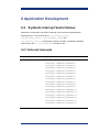
For example the SCI 2 interrupts are defined this way for H8S/2357 variant HAL:
#define
#define
#define
#define
CYGNUM_HAL_INTERRUPT_ERI2
CYGNUM_HAL_INTERRUPT_RXI2
CYGNUM_HAL_INTERRUPT_TXI2
CYGNUM_HAL_INTERRUPT_TEI2
88
89
90
91
The H8S/2357 HAL should also use the TPU channel 5 for the eCos realtime clock and
so we do not modify the following line.
#define CYGNUM_HAL_INTERRUPT_RTC CYGNUM_HAL_INTERRUPT_TGI5A
5.4.5 Variant Startup Macros
On HAL startup the file vectors.S executes some macros wich are defined in the file
variant.inc. We have to modify these macros in order to match the H8S/2357 variant
requirements. The first step is to modify the macro hal_intc_init. The H8S/2357
uses SYSCR instead of INTCR for setting the interrupt control mode.
#ifndef CYGPKG_HAL_H8S_INTC_DEFINED
#define CYGPKG_HAL_H8S_INTC_DEFINED
.macro hal_intc_init
#if defined(CYG_HAL_STARTUP_ROM) ||
defined(CYG_HAL_STARTUP_ROMRAM)
mov.b
@CYGARC_SYSCR, r0l
bclr
#4,r0l
Porting Guide
37
bset
mov.b
#endif
.endm
#endif
#5,r0l
r0l, @CYGARC_SYSCR
Because the H8S/2357 timer module is always driven with high speed clock we do not
need to make special settings in hal_timer_init and can leave this macro empty.
#ifndef CYGPKG_HAL_H8S_TIMER_DEFINED
#define CYGPKG_HAL_H8S_TIMER_DEFINED
.macro hal_timer_init
.endm
#endif
The macro hal_mon_init intializes the VSR table with the default exception VSR and
default interrupt VSR. The H8S/2674 source for this macro is also valid for the H8S/2357
variant HAL and we do not need to modify it.
5.4.6 The File var_misc.c
This file contains miscellaneous functions for a specific H8S variant. The first function is
hal_variant_init. This function executes complex variant initialisations which cannot
be done in assembly. We leave this function empty because it is nothing to do here at the
moment.
void hal_variant_init(void)
{
// Nothing to do here at the moment
}
The first thing we are goint to modify is the definition of priority bit group values. The
H8S/2357 variant uses 8 Bit interrupt priority registers. (H8S/2674 uses 16 Bit interrupt
priority registers). For H8S/2357 we need only the following three bit groups and and bit
group mask:
//--------------------------------------------------------------// Priority bit group values for prio_bit_group member of
// hal_int_reg_conf
//
#define PRIO_RESERVED
7
#define PRIO_06_TO_04
1
#define PRIO_02_TO_00
0
#define PRIO_BITGRP_MASK 1
The next thing we have to modify is the hal_int_prio_conf_table. This table stores
priority registers and the bitgroups for setting an interrupt priority for a certain interrupt
source. The H8S/2357 uses only 8 Bit registers here and so we have to change the
38
Porting Guide
whole table. You should read the chapter “Interrupt Sources” in H8S/2357 hardware
manual in order to change this table. For external H8S/2357 interrupts the table would
look like this way:
...
PRIO_CONF_TBL_ENTRY(IPR_NONE,
PRIO_CONF_TBL_ENTRY(IPR('A'),
PRIO_CONF_TBL_ENTRY(IPR('A'),
PRIO_CONF_TBL_ENTRY(IPR('B'),
PRIO_CONF_TBL_ENTRY(IPR('B'),
PRIO_CONF_TBL_ENTRY(IPR('B'),
PRIO_CONF_TBL_ENTRY(IPR('B'),
PRIO_CONF_TBL_ENTRY(IPR('C'),
PRIO_CONF_TBL_ENTRY(IPR('C'),
...
PRIO_RESERVED),
PRIO_06_TO_04),
PRIO_02_TO_00),
PRIO_06_TO_04),
PRIO_06_TO_04),
PRIO_02_TO_00),
PRIO_02_TO_00),
PRIO_06_TO_04),
PRIO_06_TO_04),
//
//
//
//
//
//
//
//
//
015
016
017
018
019
020
021
022
023
RSV
IRQ
IRQ
IRQ
IRQ
IRQ
IRQ
IRQ
IRQ
0
1
2
3
4
5
6
7
Now we have to modify the hal_int_prio_tbl[]. The H8S/2357 variant uses only 92
interrupts (vector 0 – vector 91) and therefore we have to delete some entries from this
table (should contain 92 entries).
cyg_uint8
{
7, 7,
7, 7,
7, 7,
7, 7,
7, 7,
7, 7,
};
hal_int_prio_tbl[CYGNUM_HAL_ISR_COUNT] =
7,
7,
7,
7,
7,
7,
7,
7,
7,
7,
7,
7,
7,
7,
7,
7,
7,
7,
7,
7,
7,
7,
7,
7,
7,
7,
7,
7,
7,
7,
7,
7,
7,
7,
7,
7,
7,
7,
7,
7,
7,
7,
7,
7,
7,
7,
7,
7,
7,
7,
7,
7,
7,
7,
7,
7,
7,
7,
7,
7
7,
7,
7,
7,
7,
7,
7,
7,
7,
7,
7,
7,
7,
7,
7,
7,
7,
7,
7,
7,
The hal_int_ackn_tbl[] ist the next thing we have to modify in order to match
H8S/2357 register structure. You should read the part of your H8S hardware manual
where the adresses, functions and single bits of the registers are described. This table
contains the adresses of the registers and the bits in these registers which have to be
cleared in order to acknowledge an interrupt source. Reserved vectors should contain a
zero for register address and bit to be cleared. For register addresses you should use the
symbolic names which you have defined in the module include files. Here is a small part
of the table for H8S/2357
...
ACKN_TBL_ENTRY(CYGARC_ISR,
CLR_BIT(0)),
ACKN_TBL_ENTRY(CYGARC_ISR,
CLR_BIT(1)),
ACKN_TBL_ENTRY(CYGARC_ISR,
CLR_BIT(2)),
ACKN_TBL_ENTRY(CYGARC_ISR,
CLR_BIT(3)),
ACKN_TBL_ENTRY(CYGARC_ISR,
CLR_BIT(4)),
ACKN_TBL_ENTRY(CYGARC_ISR,
CLR_BIT(5)),
ACKN_TBL_ENTRY(CYGARC_ISR,
CLR_BIT(6)),
ACKN_TBL_ENTRY(CYGARC_ISR,
CLR_BIT(7)),
ACKN_TBL_ENTRY(0,
0),
ACKN_TBL_ENTRY(CYGARC_TCSRR, CLR_BIT(7)),
ACKN_TBL_ENTRY(CYGARC_DRAMCR,CLR_BIT(4)),
ACKN_TBL_ENTRY(0,
0),
Porting Guide
//
//
//
//
//
//
//
//
//
//
//
//
016
017
018
019
020
021
022
023
024
025
026
037
IRQ 0
IRQ 1
IRQ 2
IRQ 3
IRQ 4
IRQ 5
IRQ 6
IRQ 7
SWDTEND
WOVI
CMI
RSV
39
ACKN_TBL_ENTRY(CYGARC_ADCSR, CLR_BIT(7)), // 028
...
ADI
It is also necessary to modify hal_int_mask_tbl[]. This table contains adresses of
the registers and the bits within theses registers wich have to be set in order to mask
interrupts for a certain interrupt source. Here you should also use the symbolic names
you have defined before in module register include files. Here is a small part of the table
for H8S/2357 variant. Reserved vectors should contain zeros and interrupts without mask
registers (like NMI) should contain NO_MASK_REG for register address value.
...
MASK_TBL_ENTRY(CYGARC_IER,
BIT(0)),
MASK_TBL_ENTRY(CYGARC_IER,
BIT(1)),
MASK_TBL_ENTRY(CYGARC_IER,
BIT(2)),
MASK_TBL_ENTRY(CYGARC_IER,
BIT(3)),
MASK_TBL_ENTRY(CYGARC_IER,
BIT(4)),
MASK_TBL_ENTRY(CYGARC_IER,
BIT(5)),
MASK_TBL_ENTRY(CYGARC_IER,
BIT(6)),
MASK_TBL_ENTRY(CYGARC_IER,
BIT(7)),
MASK_TBL_ENTRY(NO_MASK_REG, 0),
MASK_TBL_ENTRY(CYGARC_TCSRW, BIT(5)),
MASK_TBL_ENTRY(CYGARC_DRAMCR,BIT(3)),
MASK_TBL_ENTRY(0,
0),
MASK_TBL_ENTRY(CYGARC_ADCSR, BIT(6)),
...
//
//
//
//
//
//
//
//
//
//
//
//
//
016
017
018
019
020
021
022
023
024
025
026
027
028
IRQ 0
IRQ 1
IRQ 2
IRQ 3
IRQ 4
IRQ 5
IRQ 6
IRQ 7
SWDTEND
WOVI
CMI
RSV
ADI
Now we have to change the function hal_interrupt_set_level because the
H8S/2357 interrupt priority registers are only 8 Bit and the H8S/2674 ones are 16 Bit. The
logic of the function is right but we have to modify the sizes of the register data types and
we have to use different register access macros. First we change the size of
prio_data, mask and prio_grp_mask_tbl from 16 to 8 bit. Then we delete the last
two entries from prio_grp_mask_tbl.
void hal_interrupt_set_level(int vector, int level)
{
cyg_uint32
prio_reg;
cyg_uint8
prio_data;
cyg_uint8
mask;
int_prio_conf_t
*pint_regs;
static const cyg_uint8
prio_grp_mask_tbl[2] =
{
0x07, 0x70
};
...
40
Porting Guide
Then we change the access macros from 16 to 8 Bit. This should be all for this function in
order to work properly for H8S/2357.
HAL_READ_UINT8(prio_reg, prio_data);
mask = prio_grp_mask_tbl[pint_regs->prio_bit_group;
prio_data &= ~mask;
prio_data |= (level << (pint_regs->prio_bit_group << 2));
HAL_WRITE_UINT8(prio_reg, prio_data);
In function hal_interrupt_configure we have to change the second assertion
because H8S/2357 supports only 8 external interrupt sources.
CYG_ASSERT((CYGNUM_HAL_INTERRUPT_EXTERNAL_0 <= vector
&& CYGNUM_HAL_INTERRUPT_EXTERNAL_7 >= vector)
|| CYGNUM_HAL_INTERRUPT_NMI, "only external interrupts
and NMI are configurable" );
Then we have to change the NMI part of this function because H8S/2357 uses another
register than H8S/2674 variant for NMI configuration:
if (CYGNUM_HAL_INTERRUPT_NMI == vector)
{
HAL_READ_UINT8(CYGARC_SYSCR, reg_data);
if (up)
{
reg_data |= CYGARC_SYSCR_NMIEG_RIS;
}
else
{
reg_data &= ~CYGARC_SYSCR_NMIEG_RIS;
}
HAL_WRITE_UINT8(CYGARC_SYSCR, reg_data);
return;
}
And then we have to change the part for all other interrupts. H8S/2357 uses only one 16
Bit sense control register because it has only 8 external interrupts instead of 16 of
H8S/2674 (two 16 Bit sense control registers). So we do not need to calculate if we use
CYGARC_ISCRH ord
CYGARC_ISCRL because we only need CYGARC_ISCR and
therefore we can delete the line:
iscr = (vector <= CYGNUM_HAL_INTERRUPT_EXTERNAL_7) ?
CYGARC_ISCRL : CYGARC_ISCRH;
And the remaining lines will become a little bit simpler in H8S/2357 variant:
mask = 3 << ((vector - CYGNUM_HAL_INTERRUPT_EXTERNAL_0) << 1);
HAL_READ_UINT16(CYGARC_ISCR, reg_data);
reg_data &= ~mask;
reg_data |= (int_req_conf <<
Porting Guide
41
((vector - CYGNUM_HAL_INTERRUPT_EXTERNAL_0) << 1));
HAL_WRITE_UINT16(CYGARC_ISCR, reg_data);
The two functions hal_interrupt_attach and h8s_reset_watchdog are ok for
H8S/2357 variant and we do not need to change anything within these functions. This
should be all for the file var_misc.c. The file var_intr.S contains interrupt mask, unmask
and acknowledge functions written completely in assembly in order to make them as fast
as possible. These functions also work for H8S/2357 without any change so we do not
need to touch this file. The H8S/2357 variant is finished now.
5.5 Platform HAL Porting to Cetoni MCU2357
This chapter describes eCos platform port for Cetoni MCU2357. This is a microcontroller
unit based on the Renesas H8S/2357 microcontroller. Doing a platform port requires a
preexisting architecture and variant HAL port. This is the H8S architeture HAL and the
H8S/2357 variant HAL described in previous chapter. The MCU2357 board does not
contain any external RAM or ROM. Only the internal H8S/2357 RAM (8 KByte) and ROM
(128 KByte FLASH) are available. This is not enough for running eCos but it is possible to
run RedBoot and it is ok as an example for this porting guide.
5.5.1 HAL Platform Porting Process
The easiest way to make a new platform HAL is simply to copy an existing platform HAL
and change the files to match the new platform. For H8S architecture only one platform
HAL implementation exists at the moment – the EDOSK-2674 platform. This will be our
reference platform HAL to be copied. The first step is to create a new directory mcu2357
under packages/hal/h8s. Next we simply copy the content of the edosk2674
directory into the mcu2357 directory.
5.5.2 HAL Platform CDL
Each platform needs an entry in the ecos.db file. Here it is also a good idea to copy and
modify the existing EDOSK-2674 entry. This is the one for the Cetoni MCU2357:
package CYGPKG_HAL_H8S_H8S2357_MCU2357 {
alias
{ "Cetoni MCU2357"
hal_h8s2357_mcu2357
h8s2357_mcu2357_hal }
directory hal/h8s/mcu2357
script
hal_h8s_h8s2357_mcu2357.cdl
hardware
description "
The Cetoni MCU2357 HAL package provides the support needed to run
eCos on a Cetoni microcontroller unit with Renesas H8S/2357
microcontroller."
}
42
Porting Guide
In order to select and build the eCos library for Cetoni MCU2357 a target entry in ecos.db
is required. We simply copy the EDOSK-2674 target and modify it for the MCU2357
board.
target mcu2357 {
alias
{ "Cetoni MCU2357" }
packages
{ CYGPKG_HAL_H8S
CYGPKG_HAL_H8S_H8S2357
CYGPKG_HAL_H8S_H8S2357_MCU2357
}
description "
The Cetoni MCU2357 target provides the packages need to run
eCos on the Cetoni microcontroller unit for Renesas H8S/2357"
}
The platform CDL file contains a package entry, named according to architecture, variant
and platform, matching the package name in the ecos.db file. We rename the file
hal_h8s_h8s2674_edos2674.cdl under the mcu2357/current/cdl directory in
hal_h8s_h8s2357_mcu2357.cdl. Then we can simply modify the entries to match our
new
H8S/2357
platform.
We
remove
the
implementation
of
CYGINT_HAL_H8S_PLATFORM_LINUX_BOOT_SUPPORT because this platform does not
support booting of Linux via RedBoot. Here is the initial part of the MCU2357 CDL file:
cdl_package CYGPKG_HAL_H8S_H8S2357_MCU2357 {
display
"Cetoni MCU2357 platform"
parent
CYGPKG_HAL_H8S
requires
CYGPKG_HAL_H8S_H8S2357
implements
CYGINT_HAL_VIRTUAL_VECTOR_SUPPORT
implements
CYGINT_HAL_VIRTUAL_VECTOR_COMM_BAUD_SUPPORT
implements
CYGINT_HAL_DEBUG_GDB_STUBS
implements
CYGINT_HAL_DEBUG_GDB_STUBS_BREAK
implements
CYGINT_HAL_H8S_USE_COMMON_SCI_CODE
implements
CYGINT_HAL_H8S_USE_COMMON_DIAG_CODE
implements
CYGINT_HAL_H8S_USE_COMMON_GDB_STUB
define_header hal_h8s_h8s2357_mcu2357.h
include_dir
cyg/hal
description
"
The Cetoni MCU2357 HAL package provides the support needed to run
eCos on a Cetoni microcontroller unit for H8S/2357"
compile
plf_misc.c plf_diag.c delay_us.S
Next we have to rename the names for header files in CDL file and select a place for
VSR-Table and Virtual-Vector-Table in RAM. The H8S/2357 has 8 Kbytes internal RAM.
We place the two tables at the start of this internal RAM. (read H8S/2357 hardware
manual for description of memory map in each operating mode).
define_proc {
puts $::cdl_system_header "#define CYGBLD_HAL_TARGET_H
<pkgconf/hal_h8s_h8s2357.h>"
Porting Guide
43
puts $::cdl_system_header "#define CYGBLD_HAL_PLATFORM_H
<pkgconf/hal_h8s_h8s2357_mcu2357.h>"
puts $::cdl_system_header "#define CYGBLD_HAL_PLATFORM_IO_H
<cyg/hal/plf_io.h>"
puts $::cdl_header "#define CYG_HAL_H8S"
puts $::cdl_header "#define CYGHWR_HAL_VSR_TABLE 0xffdc00"
puts $::cdl_header "#define CYGHWR_HAL_VECTOR_TABLE 0xffde00"
puts $::cdl_header "#define HAL_PLATFORM_CPU
\"H8S/2357F-ZTAT\""
puts $::cdl_header "#define HAL_PLATFORM_BOARD \"Cetoni MCU2357\""
puts $::cdl_header "#define HAL_PLATFORM_EXTRA \"\""
}
MCU2357 board only supports ROM startup because it does not contain external RAM
and the internal H8S/2357 RAM is not enough for RAM or ROMRAM bootstrap.
Therefore we have to modify the startup part. The “calculated” option means that user
cannot change this value in configuration tool.
cdl_component CYG_HAL_STARTUP {
display
"Startup type"
flavor
data
calculated
{"ROM"}
no_define
define
-file system.h CYG_HAL_STARTUP
description
"
When targetting the Cetoni MCU2357 board, it is possible to build
the system only for ROM bootstrap because it does not have enough
RAM form RAM or RAMROM bootstrap. The ROM bootstrap requires that
the eCos application be blown into H8S/2357 FLASH."
In the CYG_HAL_STARTUP component we just have to rename EDOSK-2674 board into
Cetoni MCU2357 board. For CYGHWR_MEMORY_LAYOUT we have to change the
filenames. Because the board support only ROM startup we can remove all definitions
and filenames for any other startup type.
cdl_component CYGHWR_MEMORY_LAYOUT {
display "Memory layout"
flavor data
no_define
calculated {(CYG_HAL_STARTUP=="ROM") ? "h8s_h8s2357_mcu2357_rom" : "" }
description "
This is the memory layout used for building. It is selected according
to the startup (RAM, ROM, ROMRAM) settings."
CYGHWR_MEMORY_LAYOUT_LDI selects the memory layout linker script fragment files.
We also have to adjust these filenames.
cdl_option CYGHWR_MEMORY_LAYOUT_LDI {
display "Memory layout linker script fragment"
flavor data
no_define
define -file system.h CYGHWR_MEMORY_LAYOUT_LDI
calculated {(CYG_HAL_STARTUP == "ROM") ?
"<pkgconf/mlt_h8s_h8s2357_mcu2357_rom.ldi>" : "" }
}
44
Porting Guide
And last but not least we need to change the filenames of the memory layout header files:
cdl_option CYGHWR_MEMORY_LAYOUT_H {
display "Memory layout header file"
flavor data
no_define
define -file system.h CYGHWR_MEMORY_LAYOUT_H
calculated {(CYG_HAL_STARTUP == "ROM") ?
"<pkgconf/mlt_h8s_h8s2357_mcu2357_rom.h>" : "" }
}
Next we have to specify the MCU2357 I/O options related to serial I/O. The Cetoni
MCU2357 board supports 3 independent serial channels – the EDOSK-2674 board
supports only one serial channel. Therefore we have to do some modifications here.
cdl_component CYGPKG_HAL_H8S_H8S2357_MCU2357_IO_OPTIONS {
display "I/O related options"
flavor none
description
"
I/O related options including control over
communications channels, debug and console channel."
cdl_option CYGNUM_HAL_VIRTUAL_VECTOR_COMM_CHANNELS {
display
"Number of communication channels on the board"
flavor
data
calculated
3
description "
The H8S/2357 has three independent serial communication
channels (SCI0, SCI1 and SCI2). The Cetoni MCU2357 board
supports all three channels."
}
The Cetoni MCU2357 board supports three independent serial channels. Therefore we
can make the debug and diagnostic console channel configurable by the user. First we
set up the debug serial channel:
cdl_option CYGNUM_HAL_VIRTUAL_VECTOR_COMM_CHANNELS {
display
"Number of communication channels on the board"
flavor
data
calculated
3
description "
The H8S/2357 has three independent serial communication channels
(SCI0, SCI1 and SCI2). The Cetoni MCU2357 board supports all
three channels."
}
cdl_option CYGNUM_HAL_VIRTUAL_VECTOR_DEBUG_CHANNEL {
display
"Debug serial channel"
flavor
data
default_value 0
legal_values
0 to CYGNUM_HAL_VIRTUAL_VECTOR_COMM_CHANNELS-1
description
"
This option chooses which channel will be used to connect to a
host
running GDB. On the Cetoni MCU2357 board all three channels of
Porting Guide
45
H8S/2357 are connected to an RS-232 interface and can be used for
debugging"
}
cdl_option CYGNUM_HAL_VIRTUAL_VECTOR_DEBUG_CHANNEL_BAUD {
display
"Debug serial channel baud rate"
flavor
data
legal_values 9600 14400 19200 38400 57600 115200
default_value 57600
description
"
This option selects the baud rate used for the GDB debug channel.
The debug channel is used for debug connections to GDB.
Note: this should match the value chosen for the diagnostic port
if
}
Then we have to set up the diagnostic serial channel for the Cetoni MCU2357 board.
cdl_option CYGNUM_HAL_VIRTUAL_VECTOR_CONSOLE_CHANNEL {
display
"Diagnostic channel"
flavor data
legal_values
0 to CYGNUM_HAL_VIRTUAL_VECTOR_COMM_CHANNELS-1
default_value
1
description
"
This option chooses which channel will be used for diagnostic
output. On the Cetoni MCU2357 board only all H8S/2357 serial
channels are connected to an RS-232 interface and can be used
for diagnostic output."
}
cdl_option CYGNUM_HAL_VIRTUAL_VECTOR_CONSOLE_CHANNEL_BAUD {
display
"Diagnostic serial channel baud rate"
flavor
data
legal_values 9600 14400 19200 38400 57600 115200
default_value 57600
description
"
This option selects the baud rate used for the diagnostic port.
Note: this should match the value chosen for the GDB port if
the diagnostic and GDB port are the same."
}
Now we have to set up the real-time clock specific constants. The configuration values
CYGNUM_HAL_RTC_CONSTANTS,
CYGNUM_HAL_RTC_NUMERATOR
and
CYGNUM_HAL_RTC_DENOMINATOR for the MC2357 board are the same like the values
for EDOSK-2674 board. eCos for MCU2357 board should also operate on frequency of
100 Hz. So we do not need to change anything here.
cdl_component CYGNUM_HAL_RTC_CONSTANTS {
display
"Real-time clock constants."
flavor
none
cdl_option CYGNUM_HAL_RTC_NUMERATOR {
display
"Real-time clock numerator"
flavor
data
calculated
1000000000
description
"
46
Porting Guide
The NUMERATOR divided by the DENOMINATOR gives the number of
nanoseconds per tick."
}
cdl_option CYGNUM_HAL_RTC_DENOMINATOR {
display
"Real-time clock denominator"
flavor
data
calculated
100
description
"
The NUMERATOR divided by the DENOMINATOR gives the number of
nanoseconds per tick."
}
Next we have to enter the value for the period to be programmed into hardware timer. We
use TPU channel 5 like the EDOSK-2674 board. This is a 16 Bit counter that counts to a
maximum value of 65.535. The counter is driven by the internal clock of H8S/2357. This
clock operates on 7372800 Hz for Cetoni MCU2357 board. Because we need a
frequency of 100 Hz for eCos we need an interrupt each time the counter reaches a value
of 7372800 Hz / 100 Hz = 73728. This value is too large for 16 bit counter. Therefore we
need a clock divider for TPU. The TPU module supports a clock divider of 4. With this
clock divider the channel is driven with 7372800 Hz / 4 and we need an interrupt each
time we reach 73728 / 4 = 18432. This will be the period to be programmed into hardware
timer.
cdl_option CYGNUM_HAL_RTC_PERIOD {
display
"Real-time clock period"
flavor
data
calculated
{ 18432 }
description
"
The PERIOD is the divider to be programmed into a hardware timer
that is driven from an appropriate hardware clock, such that the
timer overflows once per tick. The MCU2357 board uses the TPU
channel 5 as hardware timer."
}
We do not need the value CYGNUM_HAL_RTC_FREQUENCY and can delete it from CDL
file. Next we have to modify the value for H8S/2357 Clock Pulse Generator input. The
MCU2357 board uses a crystal of 7.3728 MHz and we have to setup this value in CDL
file:
cdl_option CYGHWR_HAL_H8S_CPG_INPUT {
display
"OSC/Clock Frequency"
flavor
data
calculated 7372800
description "
The value of the crystal is 7.3728 MHz."
}
The next two settings CYGBLD_GLOBAL_OPTIONS and
CYGBLD_GLOBAL_COMMAND_PREFIX are also valid for MCU2357 board and we can take
them unchanged for our new board:
Porting Guide
47
cdl_component CYGBLD_GLOBAL_OPTIONS {
display "Global build options"
flavor none
parent CYGPKG_NONE
description
"
Global build options including control over
compiler flags, linker flags and choice of toolchain."
cdl_option CYGBLD_GLOBAL_COMMAND_PREFIX {
display "Global command prefix"
flavor data
no_define
default_value { "h8300-elf" }
description "
This option specifies the command prefix used when
invoking the build tools."
}
Now we have to remove the –ms2600 flags from compiler- and linker flags because the
H8S/2357 contains a H8S2000 CPU but the EDOSK-2674 board contains a H8S2600
CPU. The remaining flags are valid also for MCU2357 board and we leave them
unchanged:
cdl_option CYGBLD_GLOBAL_CFLAGS {
display "Global compiler flags"
flavor data
no_define
default_value {
CYGBLD_BUILD_FOR_DEBUG == 0 ?
"-ms -mint32 -mecos -g -O2 -Wall -Wpointer-arith
-Wstrict-prototypes -Winline -Wundef -Woverloaded-virtual
-fsigned-char -fdata-sections -fno-rtti -fno-exceptions
-finit-priority -finline-limit=100000" : \
"-ms -mint32 -mecos -g -g2 -Wall -Wpointer-arith
-Wstrict-prototypes -Winline -Wundef -Woverloaded-virtual
-fsigned-char -fdata-sections -fno-rtti -fno-exceptions
-finit-priority -finline-limit=100000" }
description
"
This option controls the global compiler flags which are used to
compile all packages by default. Individual packages may define
options which override these global flags."
}
cdl_option CYGBLD_GLOBAL_LDFLAGS {
display "Global linker flags"
flavor data
no_define
default_value {
CYGBLD_BUILD_FOR_DEBUG == 0 ?
"-ms -mint32 -mecos -g -nostdlib -Wl,--gc-sections -Wl,-static" : \
"-ms -mint32 -mecos -g -g2 -nostdlib -Wl,--gc-sections -Wl,-static"
}
description
"
This option controls the global linker flags. Individual
packages may define options which override these global flags."
}
48
Porting Guide
The next CDL configuration options CYGBLD_BUILD_FOR_DEBUG,
CYGBLD_BUILD_GDB_STUBS, CYGSEM_HAL_ROM_MONITOR,
CYGSEM_HAL_USE_ROM_MONITOR and CYGBLD_BUILD_REDBOOT_BIN are valid for
MCU2357 and we do not need to change anything here.
Now we remove the three Linux boot options BOOT_ENTRY, COMMAND_LINE and
COMMAND_START because the MCU2357 does not have enough RAM to support uCLinux
booting and there is no uCLinux port available for this platform. We can also remove the
test and build options because at the moment we do not provide platform specific tests
for MCU2357 and this board also does not need special build options.
Porting Guide
49
Now the CDL file and ecos.db entries are ready and it should be possible to load the
Cetoni MCU2357 target into the eCos configuration GUI – for MCU2357 board it looks
this way:
5.5.3 Platform include files
Within the include directory of our new platform there are a number of include files we
have copied from EDOSK-2674 platform. Now we have to look into these files in order to
see if we have to change something for MCU2357 platform.
If we look into the files then we see that we have to change nothing in the files plf_stub.h,
plf_intr.h and hal_diag.h. From file plf_io.h we can remove all register bit definitions so
that this file is empty now. We do not delete this file yet – maybe we have to provide
platform specific I/O functions or I/O register definitions later if we develop platform
drivers (for FLASH, SCI...).
5.5.3.1 platform.inc
This is the assembler include file included by vectors.S that executes low level
initializations. From this file we can delete the macro hal_intc_init because this
macro contains EDOSK-2674 specific initializations of interrupt controller. We already
50
Porting Guide
defined this macro in variant.inc – it initializes the interrupt controller there (interrupt
control mode 2).
In macro hal_memc_init we initialise MCU2357 bus- and memory controller and
general purpose I/O.
We can keep a lot of this macro but we have to change the registers and their values in
init_regs. For MCU2357 board the register initialisation values look like this (we use
the symbolic register names von module register include files of H8S/2357 variant):
...
init_regs:
INIT_REGS_DATA(CYGARC_ABWCR, 0xFF)
INIT_REGS_DATA(CYGARC_ASTCR, 0xFF)
INIT_REGS_DATA(CYGARC_BCRH,
0x00)
INIT_REGS_DATA(CYGARC_BCRL,
0x1C)
INIT_REGS_DATA(CYGARC_WCRH,
0xFF)
INIT_REGS_DATA(CYGARC_WCRL,
0xFF)
INIT_REGS_DATA(CYGARC_MCR,
0x00)
INIT_REGS_DATA(CYGARC_DRAMCR, 0x00)
INIT_REGS_DATA(CYGARC_RTCOR, 0x00)
INIT_REGS_DATA(CYGARC_P6DDR, 0x00)
INIT_REGS_DATA(CYGARC_PADDR, 0x00)
INIT_REGS_DATA(CYGARC_PBDDR, 0xFF)
INIT_REGS_DATA(CYGARC_PCDDR, 0xFF)
INIT_REGS_DATA(CYGARC_PFDDR, 0x80)
INIT_REGS_DATA(CYGARC_MSTPCRL,0x00)
.word
0
...
5.5.4 Platform source files
5.5.4.1 plf_misc.c
This file contains miscellaneous platform specific functions provided by HAL. The first
function we need to modify a little bit is hal_clock_initialize. We use TPU channel
5 like EDOSK-2674 board but we need a clock divider of 4 (EDOSK-2674 uses a clock
divider of 16) in order to get a 100 Hz frequency for eCos real-time clock. We have to
change only one single line within this function:
...
// initialize 16 bit timer - first we select timer counter clock and
// counter clearing source TGR
// Clock prescaler is 4 (clock/4) and TCNT is clear at compare match A
//
HAL_WRITE_UINT8(CYGARC_TCR5, CYGARC_TCR_CLR_CMA | CYGARC_TCR_TPSC_4);
...
Now we only need to remove the function cyg_plf_memory_segment, because the
MCU2357 board contains only one memory segment, and we are finished with this file.
Porting Guide
51
5.5.4.2 plf_diag.c
This file contains platform specific functions required for diagnostic output. This file
defines and sets up the various diagnostic channels used by a specific platform. We have
to change this file a little bit in order to match the requirements of MCU2357 board. The
first thing we are going to modify is the channels[] table for diagnostic channel data.
The EDOSK-2674 board supports only one channel but MCU2357 board supports all
three serial channels – therefore we have to enhance the table. The initialisation of the
table depends on the selected baud rate and selected debug channel in configtool.
Therefore we first insert some defines which enable compile time initialisation of serial
channels according to selected baud rate:
#if
CYGNUM_HAL_VIRTUAL_VECTOR_DEBUG_CHANNEL == 0
#define CYGNUM_HAL_SCI0_BAUD CYGNUM_HAL_VIRTUAL_VECTOR_DEBUG_CHANNEL_BAUD
#define CYGNUM_HAL_SCI1_BAUD
CYGNUM_HAL_VIRTUAL_VECTOR_CONSOLE_CHANNEL_BAUD
#define CYGNUM_HAL_SCI2_BAUD
CYGNUM_HAL_VIRTUAL_VECTOR_CONSOLE_CHANNEL_BAUD
#elif CYGNUM_HAL_VIRTUAL_VECTOR_DEBUG_CHANNEL == 1
#define CYGNUM_HAL_SCI0_BAUD
CYGNUM_HAL_VIRTUAL_VECTOR_CONSOLE_CHANNEL_BAUD
#define CYGNUM_HAL_SCI1_BAUD CYGNUM_HAL_VIRTUAL_VECTOR_DEBUG_CHANNEL_BAUD
#define CYGNUM_HAL_SCI2_BAUD
CYGNUM_HAL_VIRTUAL_VECTOR_CONSOLE_CHANNEL_BAUD
#elif CYGNUM_HAL_VIRTUAL_VECTOR_DEBUG_CHANNEL == 2
#define CYGNUM_HAL_SCI0_BAUD
CYGNUM_HAL_VIRTUAL_VECTOR_CONSOLE_CHANNEL_BAUD
#define CYGNUM_HAL_SCI1_BAUD
CYGNUM_HAL_VIRTUAL_VECTOR_CONSOLE_CHANNEL_BAUD
#define CYGNUM_HAL_SCI2_BAUD CYGNUM_HAL_VIRTUAL_VECTOR_DEBUG_CHANNEL_BAUD
#elif
#error "Wrong debug channel value"
#endif
static channel_data_t channels[CYGNUM_HAL_VIRTUAL_VECTOR_COMM_CHANNELS] =
{
CHAN_TBL_ENTRY(CYGARC_SCI0_BASE,
1000,
CYGNUM_HAL_SCI0_BAUD,
CYGNUM_HAL_INTERRUPT_RXI0),
CHAN_TBL_ENTRY(CYGARC_SCI1_BASE,
1000,
CYGNUM_HAL_SCI1_BAUD,
CYGNUM_HAL_INTERRUPT_RXI1),
CHAN_TBL_ENTRY(CYGARC_SCI2_BASE,
1000,
CYGNUM_HAL_SCI2_BAUD,
CYGNUM_HAL_INTERRUPT_RXI2),
};
52
Porting Guide
Then we have to modify the hardwired diagnostic channel – normally this channel is not
required because we support virtual vector calling interface – but for standardisation and
debug reasons we also support hardwired channel:
static channel_data_t channel =
{
(cyg_uint8 *)CYGARC_SCI0_BASE,
(cyg_uint32)1000,
CYGNUM_HAL_VIRTUAL_VECTOR_CONSOLE_CHANNEL_BAUD,
CYGNUM_HAL_INTERRUPT_RXI0
};
Well, this should be all for platform source files.
5.5.5 Memory Layout
The last thing we have to do is to setup the memory layout linker script fragments and
memory
layout
header
files.
These
files
are
located
in
directory
mcu2357\current\include\pkgconf. This directory contains linker script fragments
for ROM, RAM and ROMRAM startup. As an example we will setup the files for ROM
startup now.
For ROM startup we setup the file mlt_h8s_h8s2357_mcu2357_rom.ldi. The first
step is to setup the memory for MCU2357. The board does not provide any external ROM
or RAM memory. So we can only use the internal H8S/2357 memory. In H8S/2357
hardware manual you will find a detailed description about the memory layout. H8S/2357
contains 128 Kbytes FLASH memory and 8 Kbytes RAM. This is not enough RAM for
running eCos – but this is only a demonstration of porting process and it is enough RAM
for running RedBoot.
#include <cyg/infra/cyg_type.inc>
OUTPUT_FORMAT("elf32-h8300")
OUTPUT_ARCH(h8300s)
MEMORY
{
rom
ram
}
:
:
ORIGIN = 0x00000000, LENGTH = 0x200000
ORIGIN = 0x00ffdc00, LENGTH = 0x2000
Now we setup the single sections. We use the sections from EDOSK-2674 file and
change them for MCU2357 board. If shadow vector table should be located in ROM we
place it immediately after the hardware vector table in FLASH at address 0x200. If it
should be located in RAM then we place it after VSR table and Virtual Vector table in
RAM at address 0xffdf00.
Porting Guide
53
SECTIONS
{
SECTIONS_BEGIN
SECTION_rom_vectors
(rom, 0x000000,
LMA_EQ_VMA)
#if defined(CYGBLD_HAL_H8S_SHADOW_VECTOR_TABLE_POS_ROM)
SECTION_svects
(rom, 0x200,
LMA_EQ_VMA)
#endif
SECTION_text
(rom, ALIGN (0x4), LMA_EQ_VMA)
SECTION_fini
(rom, ALIGN (0x1), LMA_EQ_VMA)
SECTION_rodata
(rom, ALIGN (0x1), LMA_EQ_VMA)
SECTION_rodata1
(rom, ALIGN (0x1), LMA_EQ_VMA)
SECTION_fixup
(rom, ALIGN (0x1), LMA_EQ_VMA)
SECTION_gcc_except_table (rom, ALIGN (0x1), LMA_EQ_VMA)
#if defined(CYGBLD_HAL_H8S_SHADOW_VECTOR_TABLE_POS_RAM)
SECTION_svects
(ram, 0xffdf00,
FOLLOWING(.gcc_except_table))
SECTION_data
(ram, 0xffe100, FOLLOWING(.svects))
#else
SECTION_data
(ram, 0xffdf00,
FOLLOWING(.gcc_except_table))
#endif
SECTION_bss
(ram, ALIGN (0x4), LMA_EQ_VMA)
CYG_LABEL_DEFN(__heap1) = ALIGN (0x4);
SECTIONS_END
}
The last thing we have to do is to setup the memory layout header file
mlt_h8s_h8s2357_mcu2357_rom.h. We start with main flash memory. It starts at address
0x00, its size is 128 Kbytes (0x20000 Bytes) and it is read only:
// main
#define
#define
#define
flash memory 128 KByte
CYGMEM_REGION_rom (0)
CYGMEM_REGION_rom_SIZE (0x20000)
CYGMEM_REGION_rom_ATTR (CYGMEM_REGION_ATTR_R)
Next we setup values for internal H8S/2357 RAM. It starts at address 0xFFDC00 and its
size is 8 KByte (0x2000 Byte) and it is read-/writeable:
// internal RAM of H8S/2357 is 8 KByte
#define CYGMEM_REGION_ram (0xffdc00)
#define CYGMEM_REGION_ram_SIZE (0x2000)
#define CYGMEM_REGION_ram_ATTR
(CYGMEM_REGION_ATTR_R|CYGMEM_REGION_ATTR_W)
The next thing is the heap. The heap starts at the end of the RAM memory RedBoot
requires for its execution. The size depends on the RAM RedBoot needs. It ranges from
end of RedBoot in RAM to end of RAM memory (0xfffc00):
// heap
#ifndef __ASSEMBLER__
extern char CYG_LABEL_NAME (__heap1) [];
#endif
#define CYGMEM_SECTION_heap1 (CYG_LABEL_NAME (__heap1))
54
Porting Guide
#define CYGMEM_SECTION_heap1_SIZE(0xfffc00(size_t)CYG_LABEL_NAME(__heap1))
And last but not least we setup values for shadow vector table area:
// shadow vector table
#ifndef __ASSEMBLER__
extern char CYG_LABEL_NAME (_svects) [];
#endif
#define CYGMEM_SECTION_svects (CYG_LABEL_NAME (_svects))
#define CYGMEM_SECTION_svects_SIZE (0x200)
Within memory layout script fragments, header files and in platform CDL file we have set
up the memory layout for MCU2357 ROM startup. The following picture shows the
On-chip ROM
memory layout for ROM startup:
Hardware vector table
0x000000
Shadow vector table
0x000200
RedBoot ROM image
0x000400
unused FLASH memory
0x1FFFFF
On-chip RAM
External address space
VSR table
0xFFDC00
Virtual Vector table
0xFFDE00
RedBoot RAM data
0xFFDF00
heap
0xFFFBFF
Now it should be possible to compile RedBoot or the eCos library for eCos. The Cetoni
MCU2357 board shows the following RedBoot banner after startup:
RedBoot(tm) bootstrap and debug environment [ROM]
Non-certified release, version 0.8 - built 19:13:49, Mar
2 2004
Platform: Cetoni MCU2357 (H8S/2357F-ZTAT)
Copyright (C) 2000, 2001, 2002, Red Hat, Inc.
RAM: 0x00ffdc00-0x00fffc00, [0x00fff478-0x00fffc00] available
RedBoot>
Porting Guide
55
Because of the limited memory of H8S/2357 only 1.928 Bytes are available for
applications. This is not enough for eCos applications.
With the help of this porting guide it should be possible to use the EDOSK-2674 port as
base for any other H8S related eCos port. If you did an eCos port for H8S and RedBoot
does not work the first time you donwload it to your target then you should do the
following things:
•
Upload the RedBoot elf file in H8S simulator, set a breakpoint to __start and
step through the startup procedure in order to see if the program flow is right. If
you do this it is important not to execute the data_init_loop which initializes
the .data section because in simulator this would destroy content of .data
section. So if you enter datas_init_loop then you should jump behind it.
•
Check, if you have enabled the SCI modules in H8S module stop registers.
Check hardware manual for a detailed description about the single bits in module
stop register.
56
•
Check if SCI registers are initialized in the right way.
•
Check if the interrupt stack in configuration tools is large enough.
Porting Guide
6 Application Development
6.2 Symbolic Interrupt Vector Names
Whenever it is necessary to provide an interrupt vector number during application
development (i.e. on a function call to cyg_interrupt_create,
cyg_interrupt_delete, cyg_interrupt_attach and
cyg_interrupt_detach) the following symbolic constants, provided by H8S/2674
variant HAL in file var_intr_numbers.h, should be used.
6.2.1 External Interrupts
Interrupt source
Symbolic name
External pin
CYGNUM_HAL_INTERRUPT_NMI
CYGNUM_HAL_INTERRUPT_EXTERNAL_0
CYGNUM_HAL_INTERRUPT_EXTERNAL_1
CYGNUM_HAL_INTERRUPT_EXTERNAL_2
CYGNUM_HAL_INTERRUPT_EXTERNAL_3
CYGNUM_HAL_INTERRUPT_EXTERNAL_4
CYGNUM_HAL_INTERRUPT_EXTERNAL_5
CYGNUM_HAL_INTERRUPT_EXTERNAL_6
CYGNUM_HAL_INTERRUPT_EXTERNAL_7
CYGNUM_HAL_INTERRUPT_EXTERNAL_8
CYGNUM_HAL_INTERRUPT_EXTERNAL_9
CYGNUM_HAL_INTERRUPT_EXTERNAL_10
CYGNUM_HAL_INTERRUPT_EXTERNAL_11
CYGNUM_HAL_INTERRUPT_EXTERNAL_12
CYGNUM_HAL_INTERRUPT_EXTERNAL_13
CYGNUM_HAL_INTERRUPT_EXTERNAL_14
CYGNUM_HAL_INTERRUPT_EXTERNAL_15
Application Development
57
6.2.2 Miscellaneous Interrupts
Interrupt source
DTC
–
Data
Symbolic name
Transfer
CYGNUM_HAL_INTERRUPT_SWDTEND
Controller
WDT - Watchdog Timer
CYGNUM_HAL_INTERRUPT_WOVI
Refresh Controller
CYGNUM_HAL_INTERRUPT_RFSH_CMI
A/D Converter
CYGNUM_HAL_INTERRUPT_ADI
6.2.3 TPU - 16 Bit Timer Pulse Unit Interrupts
Interrupt source
Symbolic name
TPU 0 – Timer Channel 0
CYGNUM_HAL_INTERRUPT_TGI0A
CYGNUM_HAL_INTERRUPT_TGI0B
CYGNUM_HAL_INTERRUPT_TGI0C
CYGNUM_HAL_INTERRUPT_TGI0D
CYGNUM_HAL_INTERRUPT_TCI0V
TPU 1 – Timer Channel 1
CYGNUM_HAL_INTERRUPT_TGI1A
CYGNUM_HAL_INTERRUPT_TGI1B
CYGNUM_HAL_INTERRUPT_TCI1V
CYGNUM_HAL_INTERRUPT_TCI1U
TPU 2 – Timer Channel 2
CYGNUM_HAL_INTERRUPT_TGI2A
CYGNUM_HAL_INTERRUPT_TGI2B
CYGNUM_HAL_INTERRUPT_TCI2V
CYGNUM_HAL_INTERRUPT_TCI2U
TPU 3 – Timer Channel 3
CYGNUM_HAL_INTERRUPT_TGI3A
CYGNUM_HAL_INTERRUPT_TGI3B
CYGNUM_HAL_INTERRUPT_TGI3C
CYGNUM_HAL_INTERRUPT_TGI3D
CYGNUM_HAL_INTERRUPT_TCI3V
TPU 4 – Timer Channel 4
CYGNUM_HAL_INTERRUPT_TGI4A
CYGNUM_HAL_INTERRUPT_TGI4B
CYGNUM_HAL_INTERRUPT_TCI4V
58
Application Development
CYGNUM_HAL_INTERRUPT_TCI4U
TPU 5 – Timer Channel 5
CYGNUM_HAL_INTERRUPT_TGI5A
CYGNUM_HAL_INTERRUPT_TGI5B
CYGNUM_HAL_INTERRUPT_TCI5V
CYGNUM_HAL_INTERRUPT_TCI5U
6.2.4 TMR - 8 Bit Timers
Interrupt source
Symbolic name
TMR 0 – Timer Channel 0
CYGNUM_HAL_INTERRUPT_CMIA0
CYGNUM_HAL_INTERRUPT_CMIB0
CYGNUM_HAL_INTERRUPT_OVI0
TMR 1 – Timer Channel 1
CYGNUM_HAL_INTERRUPT_CMIA1
CYGNUM_HAL_INTERRUPT_CMIB1
CYGNUM_HAL_INTERRUPT_OVI1
6.2.5 DMA & EXDMA Controller Interrupts
Interrupt source
Symbolic name
DMAC – DMA Controller
CYGNUM_HAL_INTERRUPT_DEND0A
CYGNUM_HAL_INTERRUPT_DEND0B
CYGNUM_HAL_INTERRUPT_DEND1A
CYGNUM_HAL_INTERRUPT_DEND1B
EXDMAC – EXDMA Controller
CYGNUM_HAL_INTERRUPT_EXDEND0
CYGNUM_HAL_INTERRUPT_EXDEND1
CYGNUM_HAL_INTERRUPT_EXDEND2
CYGNUM_HAL_INTERRUPT_EXDEND3
Application Development
59
6.2.6 SCI – Serial Communication Interface
Interrupts
Interrupt source
Symbolic name
SCI 0 – SCI Channel 0
CYGNUM_HAL_INTERRUPT_ERI0
CYGNUM_HAL_INTERRUPT_RXI0
CYGNUM_HAL_INTERRUPT_TXI0
CYGNUM_HAL_INTERRUPT_TEI0
SCI 1 – SCI Channel 1
CYGNUM_HAL_INTERRUPT_ERI1
CYGNUM_HAL_INTERRUPT_RXI1
CYGNUM_HAL_INTERRUPT_TXI1
CYGNUM_HAL_INTERRUPT_TEI1
SCI 2 – SCI Channel 2
CYGNUM_HAL_INTERRUPT_ERI2
CYGNUM_HAL_INTERRUPT_RXI2
CYGNUM_HAL_INTERRUPT_TXI2
CYGNUM_HAL_INTERRUPT_TEI2
6.3 Interrupt Priority Levels
When calling cyg_interrupt_create it is necessary to provide an interrupt priority
level. The H8S architecture supports 8 priority levels in interrupt control mode 2 (eCos
sets up interrupt control mode 2 at startup – interrupt control mode 0 is not supported at
the moment). The following symbolic constants should be used for providing interrupt
priority levels. When assertions are enabled then other values will raise an assertion
error.
CYGNUM_HAL_INT_PRIO_LOWEST
(complies
to
CYGNUM_HAL_INT_PRIO_0)
CYGNUM_HAL_INT_PRIO_0
CYGNUM_HAL_INT_PRIO_1
CYGNUM_HAL_INT_PRIO_2
CYGNUM_HAL_INT_PRIO_3
CYGNUM_HAL_INT_PRIO_4
CYGNUM_HAL_INT_PRIO_5
CYGNUM_HAL_INT_PRIO_6
CYGNUM_HAL_INT_PRIO_7
CYGNUM_HAL_INT_PRIO_HIGHEST (complies to CYGNUM_HAL_INT_PRIO_7)
60
Application Development
NOTE
.The lowest priority CYGNUM_HAL_INT_PRIO_0
means that this interrupt is blocked and will not occur. So the
lowest priority for an interrupt which should not be blocked is
CYGNUM_HAL_INT_PRIO_1
6.4 Interrupt Configuration
It is possible to program the interrupt controller with the method for detecting an interrupt.
This can be done by a function cal to cyg_interrupt_configure. The following
EDOSK-2674 interrupts are configurable with the following configuration options. (If
level is FALSE then up selects rising or falling edge detection. If level is true the up
selects low level or high level). If assertions are enabled then all other values and value
combinations will raise an assertion error.
void
cyg_interrupt_configure(
cyg_vector_t vector,
cyg_bool_t
level,
cyg_bool_t
up
);
Falling
Rising
Low
High
Edge
Edge
Level
Level
CYGNUM_HAL_INTERRUPT_NMI
yes
yes
-
-
CYGNUM_HAL_INTERRUPT_EXTERNAL_0
yes
yes
yes
-
CYGNUM_HAL_INTERRUPT_EXTERNAL_1
yes
yes
yes
-
yes
yes
yes
-
Symbolic interrupt name
...
CYGNUM_HAL_INTERRUPT_EXTERNAL_15
Application Development
61
7 Configuring the Windows Host
7.2 Installing the Cygwin Native Tools
This installation instruction is for the eCos H8S development CD. This is a CD I have
created for fast access to all tools for a complete eCos H8S development environment.
Maybe these installation instructions are also helpful for people without this CD.
STEP 1
The first step for installing Cygwin is to execute setup.exe from Cygwin install directory on
CD.
STEP 2
The next step in the
Cygwin installation is to
select the location we
want to install from. The
options are shown in the
following dialog box. We
select Install from Local
Directory and click the
Next button.
62
Configuring the Windows Host
STEP 3
Now we want to select
the
location
of
the
Cygwin packages we
want to install, Local
Package Directory. We
set this option to the CD
directory
where
the
files
are
installation
located.
STEP 4
Next we set up the
location where we want
the
tools
Select
installed,
Root
Insatll
Directory. We set this
option to D:\cygwin
by either typing it in or
directly
clicking
the
Browse button to find
the proper directory.
As Default Text File
Type we select DOS.
We can now click the
Next button.
Configuring the Windows Host
63
STEP 5
The next step is to
select the packages we
want
to
install.
The
packages contained on
the CD ROM might not
be the latest versions
available
because
changes to the Cygwin
tools are continuously
occuring. However, the
CD-ROM
been
files
have
installed
and
configured
into
a
working eCos development system.
Click once on the View button to show the Full view. In addition to the packages which
are installed by default, it is essential to install the following packages:
gcc, make, sharutils, tcltk, wget.
Click once on the rotating arrows symbol against each of the above packages to select
them for installation.
STEP 6
After successful installation of the Cygwin tools, the dialog box shown
right is displayed. Click OK completes Cygwin installation. To ensure
proper installation of the Cygwin tools, we can run the bash program
by double clicking on the desktop shortcut created in. This should bring
up a UNIX bash shell environment. The last thing we have to do is to add the
cygwin\bin directory to the Windows environment path.
7.3 Installing H8S Cross-Development Tools
The CD or “UK’s EDOSK-2674” hompage contains pre-built versions of h8300 GNU
development tools for Cygwin. For the installation of these tools we simply have to unzip
the package containing the tools into the cygwin directory. After unzipping the tools
there should be two directories cygwin\tools\gcch8 and cygwin\tools\gdbh8.
64
Configuring the Windows Host
7.4 Installing the eCos Development Kit
The CD or “UK’s EDOSK-2674” hompage contains the latest snapshot of a working eCos
tree including the latest H8S and EDOSK-2674 sources. For installation you simply have
to execute the following steps.
STEP 1
The first step for installing eCos is to unzip the compressed eCos snapshot from CD into
a directory. For example unzipping the snapshot to D:\ will create the directory
D:\ecos.
STEP 2
The next step is to go into the directory ecos\tools\bin and execute the file
platforms.reg. This will register all supported platforms in Windows registry.
STEP 3
Now we execute the file
configtool.exe in:
ecos\tools\bin.
Because it is the first time we
execute this file we have to
specify the root of eCos repository tree. If we unzipped eCos to drive D: then this would
be D:\ecos.
STEP 4
The next step is to select a template
(Build -> Templates). Here we select
Renesas EDOSK2674 as Hardware
and redboot as Package. We can
now click the OK button.
Configuring the Windows Host
65
STEP 5
Now we have to select the
buil tools path. This is the
path where the binaries of
the
H8S
development
cross
tools
are
located. (Tools -> Path ->
Build Tools). The required directory is the cygwin\tools\cch8\bin directory.
We continue with OK.
STEP 6
The next step is to select
the user tools folder. This
is the directory where the
cygwin
binaries
are
located. Normaly hey are
located in cygwin\bin.
We proceed with OK.
STEP 7
Selecting Tools -> Platforms will bring
up the Platforms window. Here you
can
select
the
edosk2674_h8s
platform by double clicking on it. The
Modify Platform window will pop up
and you can setup or change the
arguments for GDB when executing
the tests. Normally these settings
should be OK after executing the
platforms.reg
file.
Read
the
chapter about eCos tests in this
manual for further instructions on
eCos tests.
In order to run the eCos tests from Configuration tool we have to add the GDB binaries
path cygwin\tools\gdbh8\bin (if you installed Cygwin on drive D then the path
would be D:\cygwin\tools\gdbh8\bin.
Now the eCos development is completely installed and ready for H8S development.
66
Configuring the Windows Host
8 Debugging with Insight
8.2 Starting Insight
This chapter covers only things which are specific for debugging of H8S related eCos
applications. For a general and detailed description of debugging with GDB or Insight you
should read the appropriate manuals.
For debugging of H8S eCos applications you should use GDB or Insight version v401
available at www.kpitgnutools.com. These versions have been approved to work properly
for H8S eCos development. If you start GDB or Insight then you should use the
gdb_remote_h8s.ini file available on the H8S eCos development CD or on “UK’s
EDOSK-2674 eCos page”. This file sets up GDB for debugging of H8S eCos applications.
If this file is not available then you should create an ini file with the following settings:
# set serial configuration
set remotedevice com1
set remotebaud 115200
# Set debugging of remote protocol. When enabled, each packet
# sent or received with the remote target is displayed
set debug remote 0
set debug serial 0
set debug arch 0
set debug event 0
set debug expression 0
set debug monitor 0
set debug target 0
# Set filename for remote session recording
set remotelogfile \gdb.log
# Set machine type
set architecture h8300s
# Set the maximum size of the address (in bits) in a memory packet
set remoteaddresssize 32
# Set the maximum number of bytes per memory-write packet
set remote memory-write-packet-size 64
set remote memory-write-packet-size fixed
# define additional commandos
define reset
maintenance packet r
detach
end
You then should use this ini file when starting Insight:
Debugging with Insight
67
h8300-elf-insight.exe -x gdb_remote.ini
8.3 Debugging
8.3.1 Debugging using serial line
If
we
debug
applications
using
eCos
the
serial line then we have to
set up GDB for serial
connection (File -> Target
Settings).
We have to set Target to
Remote/Serial,
Baud
Rate to the baud rate of
EDOSK-2674 board serial
line (normally this should
be 115200) and Port to
the com port connected to
EDOSK-2674 board.
For Run Options you should check Attach to Target, Download Program and Continue
from Last Stop.
If we run the eCos tests then it is a good idea to set breakpoints at cyg_test_exit and
cyg_assert_fail. So we can reset the board by typing reset in console window
when a test fails or finishes.
68
Debugging with Insight
8.3.2 Debugging via Ethernet
If
we
debug
applications
eCos
using
ethernet then we have
to
set
up
GDB
for
TCP/IP connection (File
-> Target Settings).
We have to set Target
to
Remote/TCP,
Hostname to IP address
of EDOSK-2674 board
and Port to TCP port we
have configured when
building RedBoot.
The remaining options
should be the same like the options for debugging using serial connection.
8.3.3 Special GDB commands
If we executed GDB or Insight with the gdb_remote_h8s.ini file when we have the
additional command reset. This command sends a reset package to the EDOSK-2674
board and then detaches GDB from target. The reset packet causes a reset of the
EDOSK-2674 board. So if you finished debugging and wish to restart debug another file
or restart debugging of the same file then you simply enter the reset command and you
are able to connect to target again immediately without pressing reset switch on the
board.
Debugging with Insight
69