1
STM32F302x6 STM32F302x8
Errata sheet
STM32F302x6 and STM32F302x8 Rev Z device limitations
Silicon identification
This errata sheet applies to revision Z of STMicroelectronics STM32F302x6/x8 products.
These products feature an ARM® 32-bit Cortex®-M4 CPU with FPU core, for which an
errata notice is also available (see Section 1 for details).
Section 2 gives a detailed description of the product silicon limitations.
The products are identifiable as shown in Table 1:
By the revision code marked below the order code on the device package
By the last three digits of the Internal order code printed on the box label
Table 1. Device identification(1) (2)
Sales type
Revision code(2) marked on device
STM32F302x6/x8
“Z”
1. The REV_ID bits in the DBGMCU_IDCODE register show the revision code of the device (see the
STM32F302x6/x8 reference manual for details on how to find the revision code).
2. Refer to STM32F302x6/x8 product datasheet for details on the device marking.
The full list of part numbers is shown in Table 2.
Table 2. Device summary
Reference
Part number
STM32F302x6
STM32F302C6, STM32F302K6, STM32F302R6
STM32F302x8
STM32F302C8, STM32F302K8, STM32F302R8
September 2015
DocID025990 Rev 6
1/21
www.st.com
1
STM32F302x6 STM32F302x8
Contents
Contents
1
2
ARM® Cortex®-M4 core with FPU core limitations . . . . . . . . . . . . . . . . . 5
1.1
Cortex®-M4 core with FPU interrupted loads to stack
pointer can cause erroneous behavior . . . . . . . . . . . . . . . . . . . . . . . . . . . 5
1.2
VDIV or VSQRT instructions might not complete correctly
when very short ISRs are used . . . . . . . . . . . . . . . . . . . . . . . . . . . . . . . . . 6
STM32F302x6/x8 silicon limitations . . . . . . . . . . . . . . . . . . . . . . . . . . . . 7
2.1
2.2
2.3
2.4
2.5
System limitations . . . . . . . . . . . . . . . . . . . . . . . . . . . . . . . . . . . . . . . . . . . 8
2.1.1
Wakeup sequence from Standby mode when using more than one
wakeup source . . . . . . . . . . . . . . . . . . . . . . . . . . . . . . . . . . . . . . . . . . . . 8
2.1.2
Full JTAG configuration without NJTRST pin cannot be used . . . . . . . . . 9
ADC limitations . . . . . . . . . . . . . . . . . . . . . . . . . . . . . . . . . . . . . . . . . . . . . . 9
2.2.1
Sampling time shortened in JAUTO auto delayed mode . . . . . . . . . . . . . 9
2.2.2
Injected queue of context is not available in case of JQM = 0 . . . . . . . . . 9
2.2.3
Load multiple not supported by ADC interface . . . . . . . . . . . . . . . . . . . 10
2.2.4
ADEN bit cannot be set immediately after the ADC calibration is done . 10
SPI peripheral limitations . . . . . . . . . . . . . . . . . . . . . . . . . . . . . . . . . . . . . .11
2.3.1
SPI CRC may be corrupted when a peripheral connected to the same
DMA channel of the SPI is under DMA transaction near the end of
transfer or end of transfer ‘-1’ . . . . . . . . . . . . . . . . . . . . . . . . . . . . . . . . 11
2.3.2
BSY bit may stay high at the end of a SPI data transfer in slave mode . 11
I2C peripheral limitations . . . . . . . . . . . . . . . . . . . . . . . . . . . . . . . . . . . . . 12
2.4.1
10-bit slave mode: wrong direction bit value after Read header
reception . . . . . . . . . . . . . . . . . . . . . . . . . . . . . . . . . . . . . . . . . . . . . . . . 12
2.4.2
10-bit combined with 7-bit slave mode: ADDCODE may indicate wrong
slave address detection . . . . . . . . . . . . . . . . . . . . . . . . . . . . . . . . . . . . . 13
2.4.3
Wakeup frames may not wakeup the MCU mode when STOP mode
entry follows I2C enabling . . . . . . . . . . . . . . . . . . . . . . . . . . . . . . . . . . . 13
2.4.4
Wrong behavior related with MCU Stop mode when wakeup from Stop
mode by I2C peripheral is disabled . . . . . . . . . . . . . . . . . . . . . . . . . . . . 14
2.4.5
Wakeup frame may not wakeup from STOP if tHD(STA) is close to tsu(HSI)
in Fast-mode and Fast-mode Plus . . . . . . . . . . . . . . . . . . . . . . . . . . . . . 15
2.4.6
Wrong data sampling when data set-up time (tSU;DAT) is smaller than
one I2CCLK period . . . . . . . . . . . . . . . . . . . . . . . . . . . . . . . . . . . . . . . . 16
2.4.7
Spurious Bus Error detection in master mode . . . . . . . . . . . . . . . . . . . . 16
I2S peripheral limitations . . . . . . . . . . . . . . . . . . . . . . . . . . . . . . . . . . . . . 17
DocID025990 Rev 6
2/21
3
Contents
STM32F302x6 STM32F302x8
2.5.1
2.6
2.7
USART peripheral limitations . . . . . . . . . . . . . . . . . . . . . . . . . . . . . . . . . . 17
2.6.1
When PCLK is selected as clock source for USART1, PCLK1 is used
instead of PCLK2 . . . . . . . . . . . . . . . . . . . . . . . . . . . . . . . . . . . . . . . . . . 17
2.6.2
Start bit detected too soon when sampling for NACK signal from the
SmartCard . . . . . . . . . . . . . . . . . . . . . . . . . . . . . . . . . . . . . . . . . . . . . . . 18
2.6.3
A break request can prevent the Transmission Complete flag (TC) from
being set . . . . . . . . . . . . . . . . . . . . . . . . . . . . . . . . . . . . . . . . . . . . . . . . 18
2.6.4
nRTS is active while RE = 0 or UE = 0 . . . . . . . . . . . . . . . . . . . . . . . . . 18
2.6.5
Receiver timeout counter starting in case of a 2 stop bit configuration . 19
Comparator peripheral limitation . . . . . . . . . . . . . . . . . . . . . . . . . . . . . . . 19
2.7.1
2.8
3/21
VREFINT scaler startup time from power down parameter degradation 19
GPIO peripheral limitation . . . . . . . . . . . . . . . . . . . . . . . . . . . . . . . . . . . . 19
2.8.1
3
In I2S slave mode, WS level must be set by the external master when
enabling the I2S . . . . . . . . . . . . . . . . . . . . . . . . . . . . . . . . . . . . . . . . . . . 17
GPIOx locking mechanism is not working properly for GPIOx_OTYPE
register . . . . . . . . . . . . . . . . . . . . . . . . . . . . . . . . . . . . . . . . . . . . . . . . . . 19
Revision history . . . . . . . . . . . . . . . . . . . . . . . . . . . . . . . . . . . . . . . . . . . 20
DocID025990 Rev 6
STM32F302x6 STM32F302x8
List of tables
List of tables
Table 1.
Table 2.
Table 3.
Table 4.
Table 5.
Device identification . . . . . . . . . . . . . . . . . . . . . . . . . . . . . . . . . . . . . . . . . . . . . . . . . . . . . . . 1
Device summary . . . . . . . . . . . . . . . . . . . . . . . . . . . . . . . . . . . . . . . . . . . . . . . . . . . . . . . . . . 1
Cortex®-M4 core with FPU limitations and impact on microcontroller behavior . . . . . . . . . . 5
Summary of silicon limitations . . . . . . . . . . . . . . . . . . . . . . . . . . . . . . . . . . . . . . . . . . . . . . . 7
Document revision history . . . . . . . . . . . . . . . . . . . . . . . . . . . . . . . . . . . . . . . . . . . . . . . . . 20
DocID025990 Rev 6
4/21
4
ARM® Cortex®-M4 core with FPU core limitations
STM32F302x6 STM32F302x8
ARM® Cortex®-M4 core with FPU core limitations
1
An errata notice of the STM32F302x6/x8 core is available from the following web address:
http://infocenter.arm.com.
All the described limitations are minor and related to the revision r0p1-v1 of the Cortex®-M4
core with FPU. Table 3 summarizes these limitations and their implications on the behavior
of STM32F30xxx devices.
Table 3. Cortex®-M4 core with FPU limitations and impact on microcontroller behavior
ARM ID
ARM category
752770
Cat B
Interrupted loads to SP can cause erroneous
behavior
Minor
776924
Cat B
VDIV or VSQRT instructions might not complete
correctly when very short ISRs are used
Minor
1.1
ARM summary of errata
Impact on STM32F3xxxx
Cortex®-M4 core with FPU interrupted loads to stack
pointer can cause erroneous behavior
Description
An interrupt occurring during the data-phase of a single word load to the stack pointer
(SP/R13) can cause an erroneous behavior of the device. In addition, returning from the
interrupt results in the load instruction being executed with an additional time.
For all the instructions performing an update of the base register, the base register is
erroneously updated on each execution, resulting in the stack pointer being loaded from an
incorrect memory location.
The instructions affected by this limitation are the following:
LDR SP, [Rn],#imm
LDR SP, [Rn,#imm]!
LDR SP, [Rn,#imm]
LDR SP, [Rn]
LDR SP, [Rn,Rm]
Workaround
As of today, no compiler generates these particular instructions. This limitation can only
occur with hand-written assembly code.
Both issues can be solved by replacing the direct load to the stack pointer by an
intermediate load to a general-purpose register followed by a move to the stack pointer.
Example:
Replace LDR SP, [R0] by
LDR R2,[R0]
MOV SP,R2
5/21
DocID025990 Rev 6
ARM® Cortex®-M4 core with FPU core limitations
STM32F302x6 STM32F302x8
1.2
VDIV or VSQRT instructions might not complete correctly
when very short ISRs are used
Description
On ARM® Cortex®-M4 with FPU core, 14 cycles are required to execute a VDIV or VSQRT
instruction.
This limitation is present when the following conditions are met:
A VDIV or VSQRT is executed
The destination register for VDIV or VSQRT is one of s0 - s15
An interrupt occurs and is taken
The ISR being executed does not contain a floating point instruction
14 cycles after the VDIV or VSQRT is executed, an interrupt return is executed
In this case, if there are only one or two instructions inside the interrupt service routine, then
the VDIV or VQSRT instruction does not complete correctly and the register bank and
FPSCR are not updated, meaning that these registers hold incorrect out-of-date data.
Workaround
Two workarounds are applicable:
Disable lazy context save of floating point state by clearing LSPEN to 0 (bit 30 of the
FPCCR at address 0xE000EF34).
Ensure that every ISR contains more than 2 instructions in addition to the exception
return instruction.
DocID025990 Rev 6
6/21
20
STM32F302x6/x8 silicon limitations
2
STM32F302x6 STM32F302x8
STM32F302x6/x8 silicon limitations
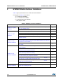
Table 4 gives quick references to all documented limitations.
The legend for Table 4 is as follows:
A = workaround available,
N = no workaround available,
P = partial workaround available,
‘-’ and grayed = fixed.
Table 4. Summary of silicon limitations
Links to silicon limitations
Section 2.1: System
limitations
Section 2.2: ADC
limitations
Section 2.3: SPI
peripheral limitations
Revision Z
Section 2.1.1: Wakeup sequence from Standby mode when using more
than one wakeup source
A
Section 2.1.2: Full JTAG configuration without NJTRST pin cannot be used
A
Section 2.2.1: Sampling time shortened in JAUTO auto delayed mode
A
Section 2.2.2: Injected queue of context is not available in case of JQM = 0
N
Section 2.2.3: Load multiple not supported by ADC interface
A
Section 2.2.4: ADEN bit cannot be set immediately after the ADC
calibration is done
A
Section 2.3.1: SPI CRC may be corrupted when a peripheral connected to
the same DMA channel of the SPI is under DMA transaction near the end
of transfer or end of transfer ‘-1’
P
Section 2.3.2: BSY bit may stay high at the end of a SPI data transfer in
slave mode
A
Section 2.4.1: 10-bit slave mode: wrong direction bit value after Read
header reception
A
Section 2.4.2: 10-bit combined with 7-bit slave mode: ADDCODE may
indicate wrong slave address detection
N
Section 2.4.3: Wakeup frames may not wakeup the MCU mode when
STOP mode entry follows I2C enabling
A
Section 2.4.4: Wrong behavior related with MCU Stop mode when wakeup
from Stop mode by I2C peripheral is disabled
A
Section 2.4.5: Wakeup frame may not wakeup from STOP if tHD(STA) is
close to tsu(HSI) in Fast-mode and Fast-mode Plus
P
Section 2.4.6: Wrong data sampling when data set-up time (tSU;DAT) is
smaller than one I2CCLK period
P
Section 2.4.7: Spurious Bus Error detection in master mode
A
Section 2.5.1: In I2S slave mode, WS level must be set by the external
master when enabling the I2S
A
2
Section 2.4: I C
peripheral limitations
Section 2.5: I2S
peripheral limitations
7/21
DocID025990 Rev 6
STM32F302x6 STM32F302x8
STM32F302x6/x8 silicon limitations
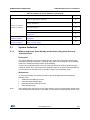
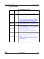
Table 4. Summary of silicon limitations (continued)
Links to silicon limitations
Section 2.6: USART
peripheral limitations
Revision Z
Section 2.6.1: When PCLK is selected as clock source for USART1,
PCLK1 is used instead of PCLK2
A
Section 2.6.2: Start bit detected too soon when sampling for NACK signal
from the SmartCard
N
Section 2.6.3: A break request can prevent the Transmission Complete flag
(TC) from being set
A
Section 2.6.4: nRTS is active while RE = 0 or UE = 0
A
Section 2.6.5: Receiver timeout counter starting in case of a 2 stop bit
configuration
A
Section 2.7: Comparator Section 2.7.1: VREFINT scaler startup time from power down parameter
peripheral limitation
degradation
N
Section 2.8: GPIO
peripheral limitation
A
Section 2.8.1: GPIOx locking mechanism is not working properly for
GPIOx_OTYPE register
2.1
System limitations
2.1.1
Wakeup sequence from Standby mode when using more than one
wakeup source
Description
The various wakeup sources are logically OR-ed in front of the rising-edge detector that
generates the wakeup flag (WUF). The WUF flag needs to be cleared prior to the Standby
mode entry, otherwise the MCU wakes up immediately.
If one of the configured wakeup sources is kept high during the clearing of WUF flag (by
setting the CWUF bit), it may mask further wakeup events on the input of the edge detector.
As a consequence, the MCU may not be able to wake up from Standby mode.
Workaround
To avoid this limitation, the following sequence should be applied before entering the
Standby mode:
Note:
Disable all used wakeup sources.
Clear all related wakeup flags.
Re-enable all used wakeup sources.
Enter Standby mode.
when applying this workaround, if one of the wakeup sources is still kept high, the MCU will
enter the Standby mode but then it will wake up immediately and generate the power reset.
DocID025990 Rev 6
8/21
20
STM32F302x6/x8 silicon limitations
2.1.2
STM32F302x6 STM32F302x8
Full JTAG configuration without NJTRST pin cannot be used
Description
When using the JTAG debug port in debug mode, the connection with the debugger is lost if
the NJTRST pin (PB4) is used as a GPIO. Only the 4-wire JTAG port configuration is
impacted.
Workaround
Use the SWD debug port instead of the full 4-wire JTAG port.
2.2
ADC limitations
2.2.1
Sampling time shortened in JAUTO auto delayed mode
Description
When the ADC is configured in JAUTO single conversion mode (CONT=0), with auto
delayed mode enabled (AUTDLY = 1), if the last regular conversion is read and a new
regular trigger arrives before the JEOS bit is cleared, the first regular conversion sampling
time is shortened by 1 cycle.
This does not apply for configuration where SMP = 000 (1.5 cycle sampling time), or if the
interval between triggers is always above the auto-injected sequence conversion period.
Workaround
The sampling time can be increased by 1 clock cycle if the situation is foreseen.
2.2.2
Injected queue of context is not available in case of JQM = 0
Description
The queue mechanism is not functional when JQM = 0. The effective queue length is equal
to 1 stage: a new context written before the previous context's consumption will lead to a
queue overflow and will be ignored.
Consequently, the ADC must be stopped before programming the JSQR register.
Workaround
None.
9/21
DocID025990 Rev 6
STM32F302x6 STM32F302x8
2.2.3
STM32F302x6/x8 silicon limitations
Load multiple not supported by ADC interface
Description
The ADC interface only supports non-sequential read accesses.
Read accesses on AHB3 port (ADC interface) using Load multiple instruction are not
supported.
The following sequence (read of JDR1, JDR2 and JDR3 injected data registers) will only
cause the R1 register to be loaded with JDR1 value, and registers R2 and R3 will be zeroed.
LDR
R0 = 0x50000080
LDMIA R0, {R1, R2, R3}
Workaround
Load multiple instruction LDMxx must be replaced by multiple single load (LD) instructions.
2.2.4
ADEN bit cannot be set immediately after the ADC calibration is done
Description
At the end of the ADC calibration, there is an internal reset of ADEN bit 4 ADC clock cycle
after the ADCAL bit cleared by hardware.
Due to that, if ADEN bit is set within those four ADC clock cycles, it will be reset by the
calibration logic and the ADC will stay disabled.
Workarounds
Continue to set the ADEN bit, until ADRDY bit become '1'.
After ADCAL is cleared, wait for a minimum of four ADC clock cycles before setting the
ADEN bit.
DocID025990 Rev 6
10/21
20
STM32F302x6/x8 silicon limitations
STM32F302x6 STM32F302x8
2.3
SPI peripheral limitations
2.3.1
SPI CRC may be corrupted when a peripheral connected to the same
DMA channel of the SPI is under DMA transaction near the end of
transfer or end of transfer ‘-1’
Description
SPI CRC may be corrupted when a peripheral connected to the same DMA channel of the
SPI is under DMA transaction near the end of transfer or end of transfer ‘-1’.
In the following conditions:
SPI is slave or master,
Full duplex or simplex mode is used,
CRC feature is enabled,
SPI is configured to manage data transfers by software (interrupt or polling),
a peripheral, mapped on the same DMA channel as the SPI, is doing DMA transfers,
the CRC may be frozen before the CRCNEXT bit is written, resulting in a CRC error.
Workaround
If the application allows it, use the DMA for SPI transfers.
2.3.2
BSY bit may stay high at the end of a SPI data transfer in slave mode
Description
In slave mode, BSY bit is not reliable to handle the end of data frame transaction due to
some bad synchronization between the CPU clock and external SCK clock provided by
master. Sporadically, the BSY bit is not cleared at the end of a data frame transfer. As a
consequence, it is not recommended to rely on BSY bit before entering low-power mode or
modifying the SPI configuration (e.g. direction of the bidirectional mode).
Workaround
Note:
11/21
When the SPI interface is in receive mode, the end of a transaction with the master can
be detected by the corresponding RXNE event when this flag is set after the last bit of
that transaction is sampled and the received data are stored.
When the following sequence is used, the synchronization issue does not occur. The
BSY bit works correctly and can be used to recognize the end of any transmission
transaction (including when RXNE is not raised in bidirectional mode):
a)
Write the last data into data register.
b)
Poll TXE flag till it becomes high to make sure the data transfer has started.
c)
Disable the SPI interface by clearing SPE bit while the last data transfer is on
going.
d)
Poll the BSY bit till it becomes low.
The second workaround can be used only when the CPU is fast enough to disable the SPI
interface after a TXE event is detected while the data frame transfer is ongoing. It cannot be
implemented when the ratio between CPU and SPI clock is low and the data frame is
particularly short. At this specific case, the timeout can be measured from the TXE event
DocID025990 Rev 6
STM32F302x6 STM32F302x8
STM32F302x6/x8 silicon limitations
instead by calculating a fixed number of CPU clock cycles corresponding to the time
necessary to complete the data frame transaction.
2.4
I2C peripheral limitations
2.4.1
10-bit slave mode: wrong direction bit value after Read header
reception
Description
Under specific conditions, the transfer direction bit DIR (bit 16 of status register I2C_ISR) is
low instead of high after reception of the 10-bit addressing Read header. Nevertheless, the
I2C operates correctly in slave transmission mode, and data can be sent using the TXIS
flag.
To see the limitation, all the following conditions have to be fulfilled:
I2C has to be configured in 10-bit addressing mode (OA1MODE is set in the I2C_OAR1
register).
The high LSBs of the I2C slave address are equal to the 10-bit addressing Read
header value (i.e. OA1[7:3] = 11110, OA1[2] = OA1[9], OA1[1] = OA1[8] and OA1[0] = 1
in the I2C_OAR1 register).
The I2C receives the 10-bit addressing Read header (0x 1111 0XX1) after the repeated
start condition to enter slave transmission mode.
As a result, the DIR bit is incorrect in slave mode under specific conditions.
Workaround
If possible, do not use these four values as 10-bit addresses in slave mode:
OA1[9:0] = 0011110001
OA1[9:0] = 0111110011
OA1[9:0] = 1011110101
OA1[9:0] = 1111110111
If one of these addresses is the I2C slave address, the DIR bit must not be used in the FW.
DocID025990 Rev 6
12/21
20
STM32F302x6/x8 silicon limitations
2.4.2
STM32F302x6 STM32F302x8
10-bit combined with 7-bit slave mode: ADDCODE may indicate wrong
slave address detection
Description
Under specific conditions, the ADDCODE (Address match code) in the I2C_ISR register
indicates a wrong slave address.
To see the limitation, all the following conditions have to be fulfilled:
The I2C slave address OA1 is enabled and configured in 10-bit mode (OA1EN=1 and
OA1MODE=1)
Another 7-bit slave address is enabled and the bits 1 to 7 of the 10-bit slave address
OA1 are equal to the 7-bit slave address, i.e. one of the configurations below is set:
–
OA2EN=1 and OA2MSK = 0 and OA1[7:1] = OA2[7:1]
–
OA2EN=1 and OA2MSK = 1 and OA1[7:2] = OA2[7:2]
–
OA2EN=1 and OA2MSK = 2 and OA1[7:3] = OA2[7:3]
–
OA2EN=1 and OA2MSK = 3 and OA1[7:4] = OA2[7:4]
–
OA2EN=1 and OA2MSK = 4 and OA1[7:5] = OA2[7:5]
–
OA2EN=1 and OA2MSK = 5 and OA1[7:6] = OA2[7:6]
–
OA2EN=1 and OA2MSK = 6 and OA1[7] = OA2[7]
–
OA2EN=1 and OA2MSK = 7
–
GCEN=1 and OA1[7:1] = 0b0000000
–
ALERTEN=1 and OA1[7:1] = 0b0001100
–
SMBDEN=1 and OA1[7:1] = 0b1100001
–
SMBHEN=1 and OA1[7:1] = 0b0001000
The master starts a transfer addressed to the 10-bit slave address OA1.
As a result, after the address reception, the ADDCODE value is OA1[7:1] equal to the 7-bit
slave address, instead of 0b11110 & OA1[9:8].
Workaround
None. If several slave addresses are enabled, mixing 10-bit and 7-bit addresses, the 10-bit
Slave address OA1 [7:1] must not be equal to the 7-bit slave address.
2.4.3
Wakeup frames may not wakeup the MCU mode when STOP mode
entry follows I2C enabling
Description
If the I2C is enabled (PE = 1) and wakeup from STOP enabled in I2C (WUPEN=1) while a
transfer occurs on the I2C bus and STOP mode is entered during the same transfer while
SCL=0, the I2C is not able to detect the following START condition. This means that if the
I2C is addressed, it will not wake up the MCU and this address is not acknowledged.
Workaround
After enabling the I2C (PE is set to 1), wait for a temporization before entering STOP mode,
to ensure that the eventual on-going frame is finished.
13/21
DocID025990 Rev 6
STM32F302x6 STM32F302x8
2.4.4
STM32F302x6/x8 silicon limitations
Wrong behavior related with MCU Stop mode when wakeup from Stop
mode by I2C peripheral is disabled
Description
When wakeup from Stop mode by I2C peripheral is disabled (WUPEN = 0) and the MCU
enters Stop mode while a transaction is on-going on the I²C bus, the following wrong
operation may occur:
1.
BUSY flag may be wrongly set when the MCU exits Stop mode. This prevents from
initiating a transfer in master mode, as the START condition cannot be sent when
BUSY is set. This failure may occur in master mode of the I2C peripheral used in multimaster I²C-bus environment.
2.
If I²C-bus clock stretching is enabled in I2C peripheral (NOSTRETCH = 0), the I2C
peripheral may pull SCL low as long as the MCU remains in Stop mode, suspending all
I²C-bus activity during that time. This may occur when the MCU enters Stop mode
during the address phase of an I²C-bus transaction, in low period of SCL. This failure
may occur in slave mode of the I2C peripheral or, in master mode of the I2C peripheral
used in multi-master I²C-bus environment. Its probability depends on the timing
configuration, operating clock frequency of I2C peripheral and the I²C-bus timing:
Workaround
Disable the I2C peripheral (PE=0) before entering Stop mode and re-enable it in Run mode.
DocID025990 Rev 6
14/21
20
STM32F302x6/x8 silicon limitations
2.4.5
STM32F302x6 STM32F302x8
Wakeup frame may not wakeup from STOP if tHD(STA) is close to tSU(HSI)
in Fast-mode and Fast-mode Plus
Description
Under specific conditions and if the START condition hold time tHD(STA) duration is very
close to the HSI start-up time duration tsu(HSI), the I2C is not able to detect the address
match and to wake up the MCU from STOP. The tsu(HSI) is between 1 µs and 2 µs (refer to
product datasheet), therefore this issue cannot occur in Standard mode. To see the
limitation, one of the conditions listed below has to be met:
Note:
Timeout detection is enabled (TIMOUTEN=1 or TEXTEN=1) and the frame before the
wakeup frame is abnormally finished due to a I2C Timeout detection (TIMOUT=1).
The slave arbitration is lost during the frame before the wakeup frame (ARLO=1).
According to standards, the slave arbitration is not applicable in I2C and used only in
SMBus, for which the transfer is done in Standard mode. Therefore when the standards
are respected this condition does not lead to the limitation.
The MCU enters STOP mode while another slave is addressed, after the address
phase and before the STOP condition (BUSY=1).
The MCU is in STOP mode and another slave is addressed before the I2C is
addressed.
The last three conditions can occur only in a multi-slave network. In STOP mode, the HSI is
powered on by the I2C when a START condition is detected (SDA falling edge while SCL is
high). The HSI is used to receive the address and it is powered off after the address
reception is case it is not the I2C slave address. If one of the conditions above is met and if
the SCL falling edge following the START condition occurs on the first cycle of the I2CCLK
clock (HSI), the address reception is not correctly done and the address match wakeup
interrupt is not generated.
Workaround
None at MCU level. To ensure the correct behavior in a multi-slave network, the master
should use a START condition hold time lower than 1 µs or greater than 2 µs.
If the wakeup frame is not acknowledged by the I2C:
15/21
If the master can program the duration of the START hold time: the master should
decrease or increase the START condition hold time for more than one HSI period and
resend the wakeup frame.
If the master can change the I2C transfer mode: the master should switch to Standard
mode and resend the wakeup frame.
DocID025990 Rev 6
STM32F302x6 STM32F302x8
2.4.6
STM32F302x6/x8 silicon limitations
Wrong data sampling when data set-up time (tSU;DAT) is smaller than
one I2CCLK period
Description
The I2C bus specification and user manual specifies a minimum data set-up time (tSU;DAT)
at:
250ns in Standard-mode,
100 ns in Fast-mode,
50 ns in Fast-mode Plus.
The I2C SDA line is not correctly sampled when tSU;DAT is smaller than one I2CCLK (I2C
clock) period: the previous SDA value is sampled instead of the current one. This can result
in a wrong slave address reception, a wrong received data byte, or a wrong received
acknowledge bit.
Workaround
Increase the I2CCLK frequency to get I2CCLK period smaller than the transmitter minimum
data set-up time. Or, if it is possible, increase the transmitter minimum data set-up time.
2.4.7
Spurious Bus Error detection in master mode
Description
In master mode, a bus error can be detected by mistake, so the BERR flag can be wrongly
raised in the status register. This will generate a spurious Bus Error interrupt if the interrupt
is enabled. A bus error detection has no effect on the transfer in master mode, therefore the
I2C transfer can continue normally.
Workaround
If a bus error interrupt is generated in master mode, the BERR flag must be cleared by
software. No other action is required and the on-going transfer can be handled normally.
DocID025990 Rev 6
16/21
20
STM32F302x6/x8 silicon limitations
STM32F302x6 STM32F302x8
2.5
I2S peripheral limitations
2.5.1
In I2S slave mode, WS level must be set by the external master when
enabling the I2S
Description
In slave mode, the WS signal level is used only to start the communication. If the I2S (in
slave mode) is enabled while the master is already sending the clock and the WS signal
level is low (for I2S protocol) or high (for the LSB- or MSB-justified mode), the slave starts
communicating data immediately. In this case, the master and slave will be desynchronized
throughout the whole communication.
Workaround
The I2S peripheral must be enabled when the external master sets the WS line at:
• High level when the I2S protocol is selected.
• Low level when the LSB- or MSB-justified mode is selected.
2.6
USART peripheral limitations
2.6.1
When PCLK is selected as clock source for USART1, PCLK1 is used
instead of PCLK2
Description
USART1 is mapped on the fast APB (APB2) and its clock can be selected among four
different sources using the USART1SW [1:0] bits in the RCC_CFGR3 register.
The default configuration selects PCLK1 (APB1 clock) as USART1 clock source instead of
PCLK2 (APB2 clock).
Workaround
There is no workaround. To reach 9 Mbaud, System Clock (SYSCLK) should be selected as
USART1 clock source.
17/21
DocID025990 Rev 6
STM32F302x6 STM32F302x8
2.6.2
STM32F302x6/x8 silicon limitations
Start bit detected too soon when sampling for NACK signal from the
SmartCard
Description
In the ISO7816, when a character parity error is incorrect, the SmartCard receiver shall
transmit a NACK error signal at (10.5 +/- 0.2) etu after the character START bit falling edge.
In this case, the USART transmitter should be able to detect correctly the NACK signal by
sampling at (11.0 +/-0.2) etu after the character START bit falling edge.
The USART peripheral used in SmartCard mode does not respect the (11 +/-0.2) etu timing,
and when the NACK falling edge reaches 10.68 etu or more, the USART misinterprets this
transition as a START bit even if the NACK is correctly detected.
Workaround
None.
2.6.3
A break request can prevent the Transmission Complete flag (TC) from
being set
Description
After the end of transmission of data (D1), the Transmission Complete (TC) flag will not be
set in the following conditions:
CTS hardware flow control is enabled.
D1 is being transmitted.
A break transfer is requested before the end of D1 transfer.
nCTS is de-asserted before the end of transfer of D1.
Workaround
If the application needs to detect the end of the data transfer, the break request should
occur after making sure that the TC flag is set.
2.6.4
nRTS is active while RE = 0 or UE = 0
Description
The nRTS line is driven low as soon as RTSE bit is set even if the USART is disabled
(UE = 0) or the receiver is disabled (RE=0), that is, not ready to receive data.
Workaround
Configure the I/O used for nRTS as alternate function after setting the UE and RE bits.
DocID025990 Rev 6
18/21
20
STM32F302x6/x8 silicon limitations
2.6.5
STM32F302x6 STM32F302x8
Receiver timeout counter starting in case of a 2 stop bit configuration
Description
In the case of a 2 stop bit configuration, the receiver timeout counter starts counting from the
end of the second stop bit of the last character instead of the end of the first stop bit.
Workaround
Change the RTO value in the USARTx_RTOR register with subtracting 1 bit duration.
2.7
Comparator peripheral limitation
2.7.1
VREFINT scaler startup time from power down parameter degradation
Description
The VREFINT scaler is an embedded voltage follower providing the VREFINT or its
fractions (1/2, 1/4 or 3/4) to the comparator input. The maximum VREFINT scaler startup
time, tS_SC(max), is not as expected for the first activation of the VREFINT scaler after
powering on the device and it can be up to 1s in worse case conditions. This maximum
value depends mainly on the voltage and temperature, see the device datasheet for more
details.
Workaround
None.
2.8
GPIO peripheral limitation
2.8.1
GPIOx locking mechanism is not working properly for GPIOx_OTYPE
register
Description
Locking of GPIOx_OTYPER[i] with i = 15..8 depends on the setting of GPIOx_LCKR[i-8]
and not from the setting of GPIOx_LCKR[i]. GPIOx_LCKR[i-8] locks GPIOx_OTYPER[i]
together with GPIOx_OTYPER[i-8]. It is not possible to lock GPIOx_OTYPER[i] with i =
15...8, without locking also GPIOx_OTYPER[i-8].
Workaround
The only way to lock GPIOx_OTYPER[i] with i=15..8 is to lock also GPIOx_OTYPER[i-8].
19/21
DocID025990 Rev 6
STM32F302x6 STM32F302x8
3
Revision history
Revision history
Table 5. Document revision history
Date
Revision
21-Mar-2014
1
Initial release.
09-Apr-2014
2
Removed all part numbers with 16KByte Flash size.
01-Oct-2014
3
Added note (2) in Table 1: Device identification
Removed the package marking information.
Added the following limitations:
– Section 2.1.1: Wakeup sequence from Standby mode when using
more than one wakeup source
– Section 2.2.3: Load multiple not supported by ADC interface
– Section 2.3.1: SPI CRC may be corrupted when a peripheral
connected to the same DMA channel of the SPI is under DMA
transaction near the end of transfer or end of transfer ‘-1’
21-Nov-2014
4
Added the following limitation:
– Section 2.2.4: ADEN bit cannot be set immediately after the ADC
calibration is done
5
Added the following limitations:
– Section 2.6.2: Start bit detected too soon when sampling for NACK
signal from the SmartCard
– Section 2.6.3: A break request can prevent the Transmission
Complete flag (TC) from being set
– Section 2.6.4: nRTS is active while RE = 0 or UE = 0
– Section 2.7.1: VREFINT scaler startup time from power down
parameter degradation
6
Updated:
– Section 2.4.4: Wrong behavior related with MCU Stop mode when
wakeup from Stop mode by I2C peripheral is disabled.
Added the following limitations:
– Section 2.1.2: Full JTAG configuration without NJTRST pin cannot
be used,
– Section 2.3.2: BSY bit may stay high at the end of a SPI data
transfer in slave mode,
– Section 2.6.5: Receiver timeout counter starting in case of a 2 stop
bit configuration,
– Section 2.4.7: Spurious Bus Error detection in master mode.
19-Feb-2015
14-Sep-2015
Changes
DocID025990 Rev 6
20/21
20
STM32F302x6 STM32F302x8
IMPORTANT NOTICE – PLEASE READ CAREFULLY
STMicroelectronics NV and its subsidiaries (“ST”) reserve the right to make changes, corrections, enhancements, modifications, and
improvements to ST products and/or to this document at any time without notice. Purchasers should obtain the latest relevant information on
ST products before placing orders. ST products are sold pursuant to ST’s terms and conditions of sale in place at the time of order
acknowledgement.
Purchasers are solely responsible for the choice, selection, and use of ST products and ST assumes no liability for application assistance or
the design of Purchasers’ products.
No license, express or implied, to any intellectual property right is granted by ST herein.
Resale of ST products with provisions different from the information set forth herein shall void any warranty granted by ST for such product.
ST and the ST logo are trademarks of ST. All other product or service names are the property of their respective owners.
Information in this document supersedes and replaces information previously supplied in any prior versions of this document.
© 2015 STMicroelectronics – All rights reserved
21/21
DocID025990 Rev 6