1
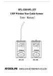
A2 Audio Test & Measurement System
User Manual
User Manual
A2 Audio Test & Measurement System
Crosstalk Function
The Crosstalk function - also called Stereo Separation - measures the interaction from one
channel to the other. The measurement is done by sending a sine signal through the one
channel, while the selective output level of the other channel (the one that is not stimulated),
is measured at a certain frequency. The resulting level ratio between the muted channel and
the active channel is the Crosstalk value.
Like with the Level Relative function, the Crosstalk measurement is performed by inserting a
narrow bandpass filter into the analyzer path.
To measure the Crosstalk, connect the generator outputs of the A2/A2-D with the inputs of
the device under test (DUT), and the two output lines of the DUT with the input channels A
and B of the A2/A2-D .
Then press the <CROSSTALK> button once, so that the display will show XTALK. Each further push toggles the function between XTALK and L.SEL.
The generator output of the active analyzer channel is automatically muted, in order to simplify the Crosstalk measurement. Furthermore, the selective bandpass filter is inserted automatically into the analyzer path of the active channel, and tuned to the oscillator frequency.
The frequency range of the filter is from 10Hz to 50kHz.
NOTE The Crosstalk value depends very much of the frequency. Since most
Crosstalk is caused by capacitive or inductive coupling, an average increase of 6dB per octave and coupling element will result.
Units
Fig. 22 Narrow Bandpass Filter Characteristics
Furthermore, in order to limit the measured bandwidth and / or to reject hum components in
the measurement signal the standard filters (400Hz HP and audio BP) may be activated.
External Source
The A2/A2-D is also capable to measure the Crosstalk from any external source like a CDplayer or a test tape instead from its own generator. The only difference to the previously
described method is, that the tracking/receive filter has to be controlled and tuned to the input frequency instead of the internal oscillator.
This can be done by pushing the <INT EXT> button
once, so that the LED behind the EXT sign lights up.
The rest of the procedure is exactly the same. The track
or tape with the test signal has to be fed to the inactive
input channel while the quiet channel is fed to the active
one.
Since the Crosstalk result is a ratio of two levels (relative value), it can be expressed in units
with no dimension only. Following units may be chosen through the <UNIT> button.
Unit
lin/log
*1
lin
%
lin
dBr
log
Calculation
U Active( filtered)
UInactive
U Active( filtered)
⋅100
UInactive
UActive ( filtered)
20 ⋅ log(
)
U Inactive
NOTE It is advisable to measure Crosstalk not only from chn. A to B, but also
from chn. B to A. There might be noticeable differences in the results.
Filters
The Crosstalk measurement automatically inserts the narrow bandpass filter (see Fig. 22)
into the active analyzer path.
V3.1
59 / 104
60 / 104
V3.1