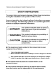
1
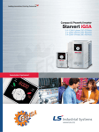
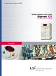
Leader in Electrics & Automation
Variable Frequency Drive / Inverter
STARVERT Series
iC5 / iG5 / iS5 / iH / iG5A / iP5A : 0.4~220kW
Automation Equipment
Simplicity-Precision, Flexibility-Standardization and
Easy to use-Diversity are the spiritual foundations of
LS Starvert variable frequency drives.
As an one-stop drive solution provider
LS is ready to offer its own competitive solutions
into the general power transmission industry.
2
Contents
�Starvert iC5
4
�Starvert iG5
5
�Starvert iS5
6
�Starvert iH
7
�Starvert iG5A
8
�Starvert iP5A
9
�Standard features &
Configuration comparison
10
3
Starvert
iC5
Dynamic & Micro single phase inverter
0.4 ~ 2.2 kW, 1ф
ф
Volts / hertz & sensorless vector control
Motor parameter auto-tuning
150% torque at 0.5Hz
0 ~ 400Hz output frequency
1 ~ 15kHz carrier frequency
Built-in process PID control
Ground fault protection
Built-in RFI filter (class A)
Built-in potentiometer
Programmable I / O
PNP / NPN selectable signal input
0 ~ 10Vdc Analog output
Optional ModBus communication board
Specifications
Model
Motor rating
Output ratings Capacity
FLA
Voltage
Frequency
Input ratings Voltage
Frequency
SV004iC5-1
[HP]
[kW]
[kVA]
[A]
[V]
[Hz]
[V]
[Hz]
0.5
1
0.4
0.75
0.95
1.9
2.5
5
Three phase, 200~230V
0~400Hz
Single phase, 200~230V (±10%)
50~60Hz (±5%)
SV015iC5-1
SV022iC5-1
SV004iC5-1F
SV008iC5-1F
SV015iC5-1F
SV022iC5-1F
2
1.5
3
8
3
2.2
4.5
12
0.5
0.4
0.95
2.5
1
0.75
1.9
5
2
1.5
3
8
3
2.2
4.5
12
Control method
Frequency setting resolution
Frequency setting accuracy
V/F ratio
Overload capacity
Torque boost
RFI filter
Multi-function input terminals
Analog output
�Sensorless vector �V/F
�Digital reference: 0.01Hz �Analog reference: 0.06Hz at 60Hz
�Digital: 0.01% of Maximum output frequency �Analog: 0.1% of Maximum output frequency
�Linear �Square �User V/F
�1 minute at 150% �30 seconds at 200% (with inverse characteristic proportional to time)
�Auto �Manual
None
Built-in (class A)
Total 5 inputs (programmable)
0~10Vdc
Input signal
�3 digits LED keypad �Terminals �ModBus communication(option)
�Analog: 0~10V, 4~20mA �Digital: Keypad �Communication: ModBus �Built-in potentiometer
�Forward �Reverse
Setting up to 8 speeds (using multi-function terminal)
0.1~6000 seconds. Maximum 8 pre-defined steps using multi-function terminals
�PID control �Up-Down operation �3-wire operation �Frequency limit �Frequency jump �Second motor function
�Slip compensation �Reverse rotation prevention �Auto restart
Interrupting output from inverter
Jog operation
Resets fault signal when protective function is active
�Frequency detection �Overload alarm �Stall �Overvoltage �Undervoltage �Inverter overheat �Run �Stop
�Constant speed �Speed search �Fault output (Relay output and Open collector output)
�Output frequency �Output current �Output voltage �DC bus voltage
Operator control
Frequency setting
Start signal
Multi-step operation
Multi-step Accel./Decel. time
Operational functions
Emergency stop
Jog
Fault reset
Output signal
Operational status
Indicator
Protective
functions
Trip
Alarm
4
SV008iC5-1
�Overvoltage �Undervoltage �Overcurrent �Inverter overheat �Motor overheat �I/O phase loss �I/O miss wiring
�Overload �External device fault 1 & 2 �Speed command loss �Hardware fault �Communication error �CPU error
�Stall �Overload
User friendly compact inverter
Starvert
0.4 ~ 4.0 kW, 3ф
ф
iG5
Space vector control technology
Volts / hertz control
150% torque at 0.5Hz
1 ~ 10kHz carrier frequency
Trip-free operation algorithm
Auto & manual torque boost
8 preset speeds
Built-in process PID
Built-in braking IGBT
Built-in ModBus / RS485 communication
PNP / NPN selectable signal
4 digits detachable display (keypad)
Parameter upload & download
0.4 ~ 1.5 kW, 1ф
ф
Specifications
Model
Motor rating
Output ratings Capacity
FLA
Voltage
Frequency
Input ratings Voltage
Frequency
SV004iG5-1U SV008iG5-1U SV015iG5-1U SV004iG5-2U SV008iG5-2U SV015iG5-2U SV022iG5-2U SV037iG5-2U SV040iG5-2U
[HP]
[kW]
[kVA]
[A]
[V]
[Hz]
[V]
[Hz]
Model
Motor rating
Output ratings Capacity
FLA
Voltage
Frequency
Input ratings Voltage
Frequency
0.5
1
0.4
0.75
1.1
1.9
3
5
Three phase, 200~230V
0~400Hz
Single phase, 200~230V (±10%)
50~60Hz (±5%)
2
1.5
3
8
0.5
0.4
1.1
3
0.5
1
0.4
0.75
1.1
1.9
1.1
2.5
Three phase, 380~480V
0~400Hz
Three phase, 380~480V (±10%)
50~60Hz (±5%)
2
1.5
3
8
3
2.2
4.5
12
2
1.5
3
4
3
2.2
4.5
6
5
3.7
6.1
8
5.4
4
6.5
9
�V/F Control (Space Vector PWM)
�Digital reference: 0.01Hz (below 99Hz) & 0.1Hz (100Hz and over) �Analog reference: 0.03Hz at 50Hz
�Digital: 0.01% of Maximum output frequency �Analog: 0.1 % of Maximum output frequency
�Linear �Square �User V/F
�1 minute at 150% �30 seconds at 200% (with inverse characteristic proportional to time)
�Auto �Manual (0~15%)
�FX (forward) �RX (reverse) �BX (inverter gate blocking) �RST (reset) �JOG (Jog)
Total 3 inputs (programmable)
0~10Vdc
Input signal
�4 digits LED keypad �Terminals �ModBus communication
�Analog: 0~10V, 4~20mA �Digital: Keypad �Communication: ModBus
�Forward �Reverse
Setting up to 8 speeds (using multi-function terminal)
0.1~6000 seconds. Maximum 8 pre-defined steps using multi-function terminals
�DC braking �Frequency limit �Frequency jump �Second motor function �Slip compensation
�Reverse rotation prevention �Auto restart �PID controls
Interrupting output from inverter
Jog operation
Resets fault signal when protective function is active
�Frequency detection �Overload alarm �Stall �Overvoltage �Undervoltage �Inverter overheat �Run �Stop
�Constant speed �Speed search �Fault output (Relay and Open collector output)
�Output frequency �Output current �Output voltage �DC voltage �rpm
Operational functions
Emergency stop
Jog
Fault reset
Output signal
Operational status
Indicator
Protective
functions
Trip
Alarm
5.4
4
6.5
17
SV037iG5-4U SV040iG5-4U
Control method
Frequency setting resolution
Frequency setting accuracy
V/F ratio
Overload capacity
Torque boost
Assigned terminals
Multi-function input terminals
Analog output
Operator control
Frequency setting
Start signal
Multi-step operation
Multi-step Accel./Decel. time
5
3.7
6.1
16
Three phase, 200~230V (±10%)
50~60Hz (±5%)
SV004iG5-4U SV008iG5-4U SV015iG5-4U SV022iG5-4U
[HP]
[kW]
[kVA]
[A]
[V]
[Hz]
[V]
[Hz]
1
0.75
1.9
5
�Overvoltage �Undervoltage �Overcurrent �Inverter overheat �Motor overheat �I/O phase loss �I/O miss wiring
�Overload �Speed command loss �Hardware fault �Communication error
�Stall �Overload
5
Starvert
iS5
Precise high torque full vector control inverter
0.75 ~ 75 kW
Sensorless & sensored vector control
Full vector, 150% torque in overall range
(continuous torque & speed control)
Motor parameter auto-tuning
1 ~ 15kHz carrier frequency
Auto speed search
Built-in process PID control
Optional multi-motor control (up to 4)
32 characters LCD & 7-segment display keypad
Parameter upload & download (LCD Loader only)
Extendable optional I / O sub-boards
Optional communication boards:
RS485, ModBus, ProfiBus-DP, DeviceNet
Built-in braking IGBT (up to 7.5kW)
Built-in keypad over 30kW
Specifications
[HP]
[kW]
[kVA]
[A]
[V]
[Hz]
[V]
[Hz]
SV008 SV015 SV022 SV037 SV055 SV075 SV110 SV150 SV185 SV220 SV300
iS5-2NU iS5-2NU iS5-2NU iS5-2NU iS5-2NU iS5-2NU iS5-2NU iS5-2NU iS5-2NU iS5-2NU iS5-2U
1
2
3
5
7.5
10
15
20
25
30
40
0.75
1.5
2.2
3.7
5.5
7.5
11
15
18.5
22
30
1.9
3
4.5
6.1
9.1
12.2
17.5
22.9
28.2
33.5
46
5
8
12
16
24
32
46
60
74
88
122
Three phase, 200~230V
0~400Hz (Sensorless vector Control: 0~300Hz, Sensored Vector Control: 0~120Hz)
Three phase, 200~230V (±10%)
50~60Hz (±5%)
SV370
iS5-2U
50
37
55
146
SV450
iS5-2U
60
45
68
180
SV550
iS5-2U
75
55
84
220
[HP]
[kW]
[kVA]
[A]
[V]
[Hz]
[V]
[Hz]
SV008 SV015 SV022 SV037 SV055 SV075 SV110 SV150 SV185 SV220 SV300
iS5-4NU iS5-4NU iS5-4NU iS5-4NU iS5-4NU iS5-4NU iS5-4NU iS5-4NU iS5-4NU iS5-4NU iS5-4U
1
2
3
5
7.5
10
15
20
25
30
40
0.75
1.5
2.2
3.7
5.5
7.5
11
15
18.5
22
30
1.9
3
4.5
6.1
9.1
12.2
18.3
22.9
29.7
34.3
45
2.5
4
6
8
12
16
24
30
39
45
61
Three phase, 380~480V
0~400Hz (�Sensorless vector Control: 0~300Hz, �Sensored Vector Control: 0~120Hz)
Three phase, 380~480V (±10%)
50~60Hz (±5%)
SV370
iS5-4U
50
37
56
75
SV450
iS5-4U
60
45
68
91
SV550
iS5-4U
75
55
82
110
Model
Motor rating
Output ratings Capacity
FLA
Voltage
Frequency
Input ratings Voltage
Frequency
Model
Motor rating
Output ratings Capacity
FLA
Voltage
Frequency
Input ratings Voltage
Frequency
Control method
Frequency setting resolution
Frequency setting accuracy
V/F ratio
Overload capacity
Torque boost
Assigned terminals
Multi-function input terminals
Analog output
�V/F Control �Sensorless vector Control �Sensored Vector Control (Velocity, Torque) selectable
�Digital reference: 0.01Hz (below 99Hz) & 0.1Hz (100Hz and over) �Analog reference: 0.03Hz at 60Hz
�Digital: 0.01% of Maximum output frequency �Analog: 0.1 % of Maximum output frequency
�Linear �Square �User V/F
�1 minute at 150% �30 seconds at 200% (with inverse characteristic proportional to time)
�Auto �Manual (0~15%)
�FX (forward) �RX (reverse) �BX (inverter gate blocking) �RST (reset) �JOG (Jog)
Total 3 inputs (programmable)
0~10V linear
Input signal
�32 character LCD keypad �4 digits LED keypad �Terminals �Communication (ModBus-RTU, RS485, ProfiBus-DP, DeviceNet, F-Net)
�Analog: 0~10V, 4~20mA, additional port for Sub-Board (0~10V) �Digital: Keypad �Communication
�Forward �Reverse
Setting up to 8 speeds (using multi-function terminal)
0.1~6000 seconds. Maximum 8 pre-defined steps using multi-function terminals
�DC braking �Frequency limit �Frequency jump �Second motor function �Slip compensation �Reverse rotation prevention
�Auto restart �Inverter by-pass �Auto-tuning �PID control
Interrupting output from inverter
Operates from Internal Sequence by Setting Multi-Function Terminal (5Way × 8Step)
Jog operation
Resets fault signal when protective function is active
�Frequency detection �Overload alarm �Stall �Overvoltage �Undervoltage �Inverter overheat �Run �Stop �Constant speed
�Speed search �Fault output (Relay and Open collector output) �Inverter by-pass �Auto-operation step �Auto-operation sequence
�Output frequency �Output current �Output voltage �DC voltage �Output torque (output voltage: 0~10V)
�Overvoltage �Undervoltage �Overcurrent �Inverter overheat �Motor overheat �I/O phase loss �I/O miss wiring �Fuse open
�Ground fault �External fault 1, 2 �Option fault �Overload �Speed command loss �Hardware fault �Communication error
�Stall �Overload �Temperature sensor fault
Operator control
Frequency setting
Start signal
Multi-step operation
Multi-step Accel./Decel. time
Operational functions
Emergency stop
Auto operation
Jog
Fault reset
Output signal
Operational status
Indicator
Protective
functions
Trip
Alarm
6
SV750
iS5-4U
100
75
100
152
Robust dual rated high power inverter
Starvert
30 ~ 220 kW, (CT & VT)
iH
Space vector control algorithm
Volts / hertz control (PWM by IGBT)
Constant / Variable torque dual rating
32bits DSP (Digital signal processor)
2 ~ 10kHz carrier frequency
Built-in process PID control
32 characters LCD display
Parameter upload & download
4 ~ 20mA analog output
Optional communication boards: RS485
Specifications
Model
Motor rating
SV030
iH-2U
40
30
SV037
iH-2U
50
37
SV045
iH-2U
60
45
SV055
iH-2U
75
55
122
46
146
55
180
68
220
83
SV030 SV037 SV045 SV055
iH-4U
iH-4U
iH-4U
iH-4U
40
50
60
75
30
37
45
55
50
60
75
100
37
45
55
75
61
75
91
110
40
50
60
70
80
96
115
125
52
62
74
80
Three phase, 380~460V
0~400Hz
Three phase, 380~460V (±10%)
50~60Hz (±5%)
SV075
iH-4U
100
75
125
90
152
100
160
103
SV090
iH-4U
125
90
150
110
183
120
228
147
SV110
iH-4U
150
110
175
132
223
145
264
170
Constant Torque [HP]
Constant Torque [kW]
Variable Torque [HP]
Variable Torque [kW]
Output ratings Constant Torque FLA [A]
(380V based) Constant Torque [kVA]
Variable Torque FLA [A]
Variable Torque [kVA]
Voltage
[V]
Frequency
[Hz]
Input ratings Voltage
[V]
Frequency
[Hz]
Three phase, 200~230V
0~400Hz
Three phase, 200~230V (±10%)
50~60Hz (±5%)
Control method
Frequency setting resolution
Frequency setting accuracy
V/F ratio
Constant Torque
Overload
capacity
Variable Torque
Torque boost
Assigned terminals
Multi-function input terminals
Analog output
�V/F Control (Space Vector PWM)
�Digital reference: 0.01Hz (below 99Hz) & 0.1Hz (100Hz and over) �Analog reference: 0.03Hz at 60Hz
�Digital: 0.01% of Maximum output frequency �Analog: 0.1 % of Maximum output frequency
�Linear �Non-linear �User V/F
�1 minute at 150% �0.5 seconds at 200% (with inverse characteristic proportional to time)
�1 minute at 110% �0.5 seconds at 150% (with inverse characteristic proportional to time)
�Auto �Manual (0~20%)
�FX (forward) �RX (reverse) �BX (inverter gate blocking) �RST (reset)
Total 6 inputs (programmable)
�0~10V pulse �4~20mA linear
Input signal
Operator control
Frequency setting
Start signal
Multi-step operation
Multi-step Accel./Decel. time
Operational functions
Emergency stop
Jog
Fault reset
Output signal
Operational status
�32 character LCD keypad �Terminals �Communication (RS-485: LSBus)
�Analog: 0~10V, 4~20mA, additional port for Sub-Board (0~10V) �Digital: Keypad �Communication
�Forward �Reverse
Setting up to 8 speeds (using multi-function terminal)
0.1~6000 seconds. Maximum 8 pre-defined steps using multi-function terminals
�DC braking �Frequency limit �Frequency jump �Slip compensation �PI control �Stall prevention
Interrupting output from inverter
Jog operation
Resets fault signal when protective function is active
�Frequency detection �Overload alarm �Stall �Overvoltage �Undervoltage �Inverter overheat �Run �Stop
�Constant speed �Speed search
�Output frequency �Output current �Output voltage �rpm
Indicator
Protective
functions
Trip
Alarm
SV132
iH-4U
175
132
215
160
264
170
330
213
SV160
iH-4U
215
160
250
185
325
200
361
233
SV220
iH-4U
300
220
350
280
432
280
477
307
�Overvoltage �Undervoltage �Overcurrent �Inverter overheat �Motor overheat �Fuse open �Ground fault �Overload
�Main CPU error
�Stall �Overload
7
Starvert
iG5A
iG5A
Powerful & compact sensorless vector control inverter
0.4 ~ 7.5 kW
Extremely compact in its size
Volts / hertz and sensorless vector control
150% torque in overall range
Motor parameter auto-tuning at stop mode
Changing carrier frequency as per Module temperature
Ground fault detection during run
Built-in process PID control
Up / down & 3-wire operational function
Optional remote keypad
0 ~ 10Vdc, -10 ~ +10Vdc Analog Input
PNP / NPN selectable signal input
Selectable configured I / O
Built-in RS485 (LSBus, ModBus-RTU) communication
Built-in braking IGBT
Cooling fan On / Off control
Specifications
Model
Motor rating
Output ratings Capacity
FLA
Voltage
Frequency
Input ratings Voltage
Frequency
SV004iG5A-2
[HP]
[kW]
[kVA]
[A]
[V]
[Hz]
[V]
[Hz]
Model
Motor rating
Output ratings Capacity
FLA
Voltage
Frequency
Input ratings Voltage
Frequency
Control method
Frequency setting resolution
Frequency setting accuracy
V/F ratio
Overload capacity
Torque boost
Multi-function input terminals
Analog output
SV004iG5A-4
[HP]
[kW]
[kVA]
[A]
[V]
[Hz]
[V]
[Hz]
SV008iG5A-2
SV015iG5A-2
SV022iG5A-2
SV037iG5A-2
SV040iG5A-2
SV055iG5A-2
SV075iG5A-2
2
1.5
3
8
3
2.2
4.5
12
5
3.7
6.1
16
5.4
4
6.5
17
7.5
5.5
9.1
24
10
7.5
12.2
32
SV015iG5A-4
SV022iG5A-4
SV037iG5A-4
SV040iG5A-4
SV055iG5A-4
SV075iG5A-4
3
2.2
4.5
6
5
3.7
6.1
8
5.4
4
6.9
9
7.5
5.5
9.1
12
10
7.5
12.2
16
0.5
1
0.4
0.75
0.95
1.9
2.5
5
Three phase, 200~230V
0~400Hz
Three phase, 200~230V (-15%, +10%)
50~60Hz (±5%)
SV008iG5A-4
0.5
1
0.4
0.75
0.95
1.9
1.25
2.5
Three phase, 380~480V
0~400Hz
Three phase, 380~480V (-15%, +10%)
50~60Hz (±5%)
2
1.5
3
4
�V/F Control �Sensorless vector Control
�Digital reference: 0.01Hz (below 99Hz) & 0.1Hz (100Hz and over) �Analog reference: 0.06Hz at 60Hz
�Digital: 0.01% of Maximum output frequency �Analog: 0.1 % of Maximum output frequency
�Linear �Square �User V/F
�1 minute at 150% �30 seconds at 200% (with inverse characteristic proportional to time)
�Auto �Manual (0~15%)
Total 8 inputs (programmable)
0~10V linear
Input signal
Operator control
�4 digits LED keypad �Terminals �Communication (LSBus, ModBus-RTU)
Frequency setting
�Analog: 0~10V, 0(4)~20mA �Digital: Keypad �Communication
Multi-step operation
Setting up to 8 speeds (using multi-function terminal)
Multi-step Accel./Decel. time 0.1~6000 seconds. Maximum 8 pre-defined steps using multi-function terminals
�DC braking �Frequency limit �Frequency jump �Second motor function �Slip compensation �Reverse rotation prevention
Operational functions
�Auto restart �Inverter by-pass �Auto-tuning �PID control
Emergency stop
Interrupting output from inverter
Jog
Jog operation
Fault reset
Resets fault signal when protective function is active
Output signal
�Frequency detection �Overload alarm �Stall �Overvoltage �Undervoltage �Inverter overheat �Run �Stop �Constant speed
Operational status
�Speed search �Fault output (Relay and Open collector output) �Inverter by-pass �Auto-operation step �Auto-operation sequence
Indicator
�Output frequency �Output current �Output voltage �DC voltage �Output torque (output voltage: 0~10V)
Protective
functions
Trip
Alarm
8
�Overvoltage �Undervoltage �Overcurrent �Inverter overheat �Motor overheat (i2t) �Fan failure
�Overload �Speed command loss �Hardware fault �Communication error �Input/output phase loss �Power module failure
�Stall �Overload �Temperature sensor fault
Fan & Pump exclusive use inverter
Starvert
5.5 ~ 90 kW
iP5A
Variable torque rating for HVAC and pump
Volts / hertz and sensorless vector control
150% torque in overall range
Motor parameter auto-tuning
High speed 32 bits Digital signal processor
0.7 ~ 15kHz carrier frequency
Built-in multi-motor control (up to 4)
Built-in process PID control
Up / Down & 3-wire operational function
Built-in ModBus (RS485) communication
0 ~ 10Vdc, -10 ~ +10Vdc Analog Input
PNP / NPN selectable signal input
External (NTC/PTC) input
Optional extendable sub-boards, ProfiBus & DeviceNet
(Soon to be released)
Optional braking unit
Cooling fan On / Off control (above 37kW)
Specifications
SV055
SV075
SV110
SV150
iP5A-2
iP5A-2
iP5A-2
iP5A-2
7.5
10
15
20
5.5
7.5
11
15
9.1
12.2
17.5
22.9
24
32
46
60
Three phase, 200~230V
0~120Hz
Three phase, 200~230V (-15%, +10%)
50~60Hz (±5%)
SV185
iP5A-2
25
18.5
28.2
74
SV220
iP5A-2
30
22
33.5
88
SV300
iP5A-2
40
30
46
122
Variable torque [HP]
Variable torque [kW]
Output ratings Variable torque [kVA]
Variable torque FLA [A]
Voltage
[V]
Frequency
[Hz]
Input ratings Voltage
[V]
Frequency
[Hz]
SV055
SV075
SV110
SV150
iP5A-4
iP5A-4
iP5A-4
iP5A-4
7.5
10
15
20
5.5
7.5
11
15
9.1
12.2
18.3
22.9
12
16
24
30
Three phase, 380~480V
0~120Hz
Three phase, 380~480V (-15%, +10%)
50~60Hz (±5%)
SV185
iP5A-4
25
18.5
29.7
39
SV220
iP5A-4
30
22
34.3
45
SV300
iP5A-4
40
30
45
61
Control method
Frequency setting resolution
Frequency setting accuracy
V/F ratio
Overload capacity
Torque boost
Multi-function input terminals
Analog output
�V/F Control �Sensorless vector Control
�Digital reference: 0.01Hz (below 99Hz) & 0.1Hz (100Hz and over) �Analog reference: 0.06Hz at 60Hz
�Digital: 0.01% of Maximum output frequency �Analog: 0.1 % of Maximum output frequency
�Linear �Square �User V/F
�1 minute at 110% �4 seconds at 150% (with inverse characteristic proportional to time)
�Auto �Manual (0~15%)
Total 8 inputs (programmable)
0~10V linear
Model
Motor rating
Variable torque [HP]
Variable torque [kW]
Output ratings Variable torque [kVA]
Variable torque FLA [A]
Voltage
[V]
Frequency
[Hz]
Input ratings Voltage
[V]
Frequency
[Hz]
Model
Motor rating
Input signal
SV370
iP5A-4
50
37
57.2
75
SV450
iP5A-4
60
45
69.4
91
SV550
iP5A-4
75
55
83.8
110
SV750
iP5A-4
100
75
115.8
152
SV900
iP5A-4
125
90
139.5
183
�32 character LCD keypad �4 digits LED keypad �Terminals �Modbus-RTU communication
�Optional ModBus-RTU, RS485, ProfiBus-DP, DeviceNet, F-Net (Soon to be released)
Frequency setting
�Analog: 0~10V, 0(4)~20mA, additional port for Sub-Board (0~10V) �Digital: Keypad �Communication
Start signal
�Forward �Reverse
Multi-step operation
Setting up to 16 speeds (using multi-function terminal)
Multi-step Accel./Decel. time 0.1~6000 seconds. Maximum 8 pre-defined steps using multi-function terminals
�DC braking �Frequency limit �Frequency jump �Second motor function �Slip compensation
Operational functions
�Reverse rotation prevention �Auto restart �Inverter by-pass �Auto-tuning �PID control
Emergency stop
Interrupting output from inverter
Jog
Jog operation
Fault reset
Resets fault signal when protective function is active
Output signal
�Frequency detection �Overload alarm �Stall �Overvoltage �Undervoltage �Inverter overheat �Run �Stop �Constant speed
Operational status
�Speed search �Fault output (Relay and Open collector output) �Inverter by-pass �Auto-operation step �Auto-operation sequence
Indicator
�Output frequency �Output current �Output voltage �DC voltage �Output torque (output voltage: 0~10V)
Protective
functions
Operator control
Trip
Alarm
�Overvoltage �Undervoltage �Overcurrent �Inverter overheat �Motor overheat �I/O phase loss �I/O miss wiring �Fuse open
�Ground fault �External fault 1, 2 �Option fault �Overload �Speed command loss �Hardware fault �Communication error
�Stall �Overload �Temperature sensor fault
9
&
Standard features
Configuration comparison
Comparison Table
Enclosure
Rating
Input voltage margin
Carrier frequency
Braking Torque
Output Frequency
Control method
Keypad
Operator control
Built-in potentiometer
PNP / NPN selectable signal
Communication
I/O extension
Software features
Analog input
Analog output
Remote option
Ambient temperature
10
IP00
IP20
NEMA 1
Single phase
Three phase
Constant torque
Variable torque
without optional resistor
with optional resistor
iC5
iG5
iS5
●
●
○
●
0.4~2.2kW
Optional
0.4~1.5kW
0.4~4kW
0.75~75kW
●
●
●
-10~+10%
1~15kHz
20%
-10~+10%
1~10kHz
20%
150%
0~400Hz
-10~+10%
1~15kHz
100%
150%
0~400Hz
●
●
●
●
0~400Hz
V/F
Sensorless vector
sensored vector
Fixed
Removable
LCD keypad
4 digits 7-segment keypad
3 digits 7-segment keypad
RS485
Modbus-RTU
Profibus DP
DeviceNet
F-Net (LS)
3 Sub-boards
Encoder feedback
Flexible I/O
Cooling fan On/Off control
Auto-tuning
PI control
PID control
Multi-motor control
0~10V
-10~+10V
0~20 mA, 4~20mA
1 × 0~10V
2 × 0~10V
4~20 mA
2 meter LS cable
3 meter LS cable
5 meter LS cable
●
●
●
●
●
●
Optional
Optional
●
●
●
●
Optional
(built-in)
built-in
Optional
Optional
Optional
Optional
Optional
●
●
●
●
●
●
●
●
●
●
●
●
●
●
●
●
○(Sub board)
●
●
●
●
●
●
-10~40℃
-10~40℃
-10~50℃
●
●
●
RFI Filters
Class A
Class B
Built-in
Footprint *
Standard *
Footprint
Standard
Footprint
Standard
0.4
~ 2.2kW
iH
iG5A
iP5A
●
●
●
Optional
UL Type1
30~280kW
0.4~7.5kW
5.5~90kW (VT only)
●
●
●
-10~+10%
2~10kHz
20%
150%
0~400Hz
-15~+10%
0.7~15kHz
20%
150%
0~400Hz
-15~+10%
0.7~15kHz
100%
150%
0~120Hz
●
●
●
●
●
●
●
●
●
●
Optional
Optional
Optional
(Optional) *
iC5
0.4
~ 4.0kW iG5
0.75
~ 75kW iS5
30
~ 280kW iH
0.4
~ 7.5kW iG5A
5.5
~ 90kW iP5A
Footprint
Standard
Footprint
Standard
Built-in *
Built-in *
Standard *
Standard
Built-in**
Standard *
Built-in *
Standard *
* In progress.
●
●
●
(built-in)
built-in
Optional
built-in
Optional
Optional
Optional
●
●
●
●
●
Driveview
�
Monitoring software
Versatile, easy-to-use software for LS
Inverter
Provides intuitive means for monitoring,
control and commissioning of Inverter
Runs on RS-232 / 485 serial network
connection
Designed for Microsoft Windows 95
or later
Keypad emulator
Graphic monitor
Parameter editor
Text monitor
�
�
●
●
●
●
●
●
●
●
●
●(5m)
●(10m)
-10~40℃
* By using iS5 communication card.
●
●
●
●
●
●
●
●
●
●
●
●
●
●
●
●
-10~50℃
-10~50℃
11
Leader in Electrics & Automation
� For your safety, please read user's manual thoroughly before operating.
� Contact the nearest authorized service facility for examination, repair, or adjustment.
� Please contact qualified service technician when you need maintenance.
Do not disassemble or repair by yourself!
Safety Instructions
� Any maintenance and inspection shall be performed by the personnel having expertise concerned.
www.lsis.biz
� HEAD OFFICE
Yonsei Jaedan Severance Bldg., 84-11, Namdaemunno 5ga,
Jung-gu, Seoul, 100-753, Korea
Tel. (82-2)2034-4870
Fax. (82-2)2034-4713
� Global Network
�LS Industrial Systems Tokyo Office �
�Tokyo, Japan
Address: 16F, Higashi-Kan, Akasaka Twin Towers 17-22, 2-chome, Akasaka, Minato-ku Tokyo 107-8470, Japan
Tel: 81-3-3582-9128 Fax: 81-3-3582-0065 e-mail: [email protected]
�LS Industrial Systems Dubai Rep. Office �
�Dubai, U.A.E
Address: P.O.Box-114216, API World Tower, 303B, Sheikh Zayed road, Dubai, UAE.
Tel: 971-4-3328289 Fax: 971-4-3329444 e-mail: [email protected]
�LS-VINA Industrial Systems Co., Ltd �
�Hanoi, Vietnam
Address: LSIS VINA Congty che tao may dien Viet-Hung Dong Anh Hanoi, Vietnam
Tel: 84-4-882-0222 Fax: 84-4-882-0220 e-mail: [email protected]
�LS Industrial Systems Hanoi Office �
�Hanoi, Vietnam
Address: Room C21, 5Th Floor, Horison Hotel, 40 Cat Linh , Hanoi, Vietnam
Tel: 84-4-736-6270/1 Fax: 84-4-736-6269
�Dalian LS Industrial Systems Co., Ltd. �
�Dalian, China
Address: No. 15 Liaohexi 3 Road, Economic and Technical Development zone, Dalian, China
Tel: 86-411-8273-7777 Fax: 86-411-8730-7560 e-mail: [email protected]
�LS Industrial Systems (Wuxi) Co., Ltd. �
�Wuxi, China
Address: 102-A National High&New Tech Industrial Development Area, Wuxi, Jiangsu, China
Tel: 86-510-534-6666 Fax: 86-510-522-4078 e-mail: [email protected]
�LS Industrial Systems International Trading (Shanghai) Co., Ltd �
�Shanghai, China
Address: Room E-G, 12 th Floor Huamin Empire Plaza, No.726, West Yan’an Road Shanghai 200050, P.R. China
Tel: 86-21-6278-4291 Fax: 86-21-6278-4372 e-mail: [email protected]
�LS Industrial Systems Shanghai Office �
�Shanghai, China
Address: Room 1705~1707, 17th Floor Xinda Commercial Building, No.322, Xian Xia Road Shanghai 200336, China
Tel: 86-21-6208-7610 Fax: 86-21-6278-4292
�LS Industrial Systems Beijing Office �
�Beijing, China
Address: B-Tower 17 Fl. Beijing Global Trade Center B/D. No. 36, BeisanhUanDong-Lu, DongCheong-District,
Beijing 100013, P.R. China
Tel: 86-10-6462-3254 Fax: 86-10-6462-3236 e-mail: [email protected]
�LS Industrial Systems Guangzhou Office �
�Guangzhou, China
Address: Room 1403, 14F, New Poly Tower, 2 Zhongshan Liu Road, Guangzhou, China
Tel: 86-20-8326-6754 Fax: 86-20-8326-6287 e-mail: [email protected]
�LS Industrial Systems Chengdu Office �
�Chengdu, China
Address: 12Floor, Guodong Building, No52 Jindun Road Chengdu, 610041, P.R. China
Tel: 86-28-8612-9151 Fax: 86-28-8612-9236 e-mail: [email protected],com
�LS Industrial Systems Qingdao Office �
�Qingdao, China
Specifications in this catalog are subject to change without notice due to
continuous product development and improvement.
2008. 01
Address: 7B40,Haixin Guangchang Shenye Building B, No. 9, Shangdong Road Qingdao, China
Tel: 86-532-580-2539 Fax: 86-532-583-3793 e-mail: [email protected]
Starvert Series (E) 2003.04/(20) 2008. 01 Printed in Korea
STAFF