1
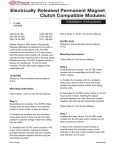
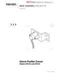
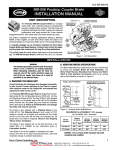
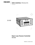
®
MEX (55) 53 63 23 31
DIST. AUTORIZADO QRO (442) 1 95 72 60
MTY (81) 83 54 10 18
[email protected]
WEB CONTROL PRODUCTS
User Manual
Tension Controller
RSTC1000
FORM NO. L-21204-B-0705
®
MEX (55) 53 63 23 31
DIST. AUTORIZADO QRO (442) 1 95 72 60
MTY (81) 83 54 10 18
[email protected]
DANGER
Read this manual carefully before installation and operation.
Follow Nexen’s instructions and integrate this unit into your system with care.
This unit should be installed, operated and maintained by qualified personnel ONLY.
Improper installation can damage your system or cause injury or death.
Comply with all applicable codes.
Manufacturers’ Declaration
In accordance with the CE machine directive 98/37/EC, Appendix II B
We hereby declare that the pneumatic/mechanical components described in this manual as well as their individual components are intended, in the configuration in which they have been supplied, to be integrated into
a machine.
They must not be put into service until the machinery into which it is to be incorporated has been declared in
conformity with the provisions of the Directive mentioned above or its amendments.
All Nexen products are designed in accordance with the manufacturing directives for pneumatic systems according to EN 983.
In accordance with Nexen’s established policy of constant product improvement, the specifications contained in this
manual are subject to change without notice. Technical data listed in this manual are based on the latest information
available at the time of printing and are also subject to change without notice.
Technical Support:
800-843-7445
(651) 484-5900
www.nexengroup.com
Nexen Group, Inc.
560 Oak Grove Parkway
Vadnais Heights, MN 55127
ISO 9001 Certified
FORM NO. L-21204-B-0705
2
Copyright 2005 Nexen Group, Inc.
®
MEX (55) 53 63 23 31
DIST. AUTORIZADO QRO (442) 1 95 72 60
MTY (81) 83 54 10 18
[email protected]
Table of Contents
Introduction ----------------------------------------------------------------------------------------------------------------------------------------4
Wiring Installation Guidelines --------------------------------------------------------------------------------------------------5
Installation -----------------------------------------------------------------------------------------------------------------------------6
Electrical Connections ------------------------------------------------------------------------------------------------------------7
Input/Output Descriptions -----------------------------------------------------------------------------------------------10
Modbus RS485 Communications -----------------------------------------------------------------------------------------12
Setup --------------------------------------------------------------------------------------------------------------------------------- 13
RSTC1000 to PC USB Communications -------------------------------------------------------------------------13
Display Window --------------------------------------------------------------------------------------------------------------13
Setup Window----------------------------------------------------------------------------------------------------------------13
Torque Actuator --------------------------------------------------------------------------------------------------------------14
Tension Zone ------------------------------------------------------------------------------------------------------------------14
Alarms ---------------------------------------------------------------------------------------------------------------------------15
Web ------------------------------------------------------------------------------------------------------------------------------15
Outputs -------------------------------------------------------------------------------------------------------------------------15
Signal Calibration -----------------------------------------------------------------------------------------------------------------16
Tension Signal Calibration------------------------------------------------------------------------------------------------16
Diameter Signal Calibration ---------------------------------------------------------------------------------------------17
Run/Stop Signal Selection -----------------------------------------------------------------------------------------------17
Tuning ------------------------------------------------------------------------------------------------------------------------------- 19
RSTC1000 Tuning Window ---------------------------------------------------------------------------------------------19
Tuning Procedure ------------------------------------------------------------------------------------------------------------19
Setpoint -------------------------------------------------------------------------------------------------------------------------20
Advanced -----------------------------------------------------------------------------------------------------------------------20
Taper Tension -----------------------------------------------------------------------------------------------------------------21
Modbus Port Setup -------------------------------------------------------------------------------------------------------------22
Operation ----------------------------------------------------------------------------------------------------------------------------22
Manual Control ---------------------------------------------------------------------------------------------------------------22
Unwind Application ---------------------------------------------------------------------------------------------------------23
Splicing Unwind Application --------------------------------------------------------------------------------------------23
Wind Application ------------------------------------------------------------------------------------------------------------24
Splicing Wind Application------------------------------------------------------------------------------------------------24
Spring Disengaged Clutch -----------------------------------------------------------------------------------------------25
Mid-Process Application --------------------------------------------------------------------------------------------------25
Diagnostics --------------------------------------------------------------------------------------------------------------------25
Specifications ----------------------------------------------------------------------------------------------------------------------26
Part Numbers ----------------------------------------------------------------------------------------------------------------------26
Troubleshooting -------------------------------------------------------------------------------------------------------------------27
Service Instructions --------------------------------------------------------------------------------------------------------------28
Appendix -----------------------------------------------------------------------------------------------------------------------------28
3
FORM NO. L-21204-B-0705
®
MEX (55) 53 63 23 31
DIST. AUTORIZADO QRO (442) 1 95 72 60
MTY (81) 83 54 10 18
[email protected]
INTRODUCTION
The Nexen RSTC1000 is used to control web tension, relying on load cell based tension sensors to measure web tension. As a part of a tension control system, the RSTC1000 measures the web’s tension and corrects tension errors by
sending a signal to change the torque output of brakes, clutches, and motor drive systems. The RSTC1000 automatically
adapts to changes in inertia and torque as roll diameters change. This ensures constant/stable tension at all times and
allows for faster accelerations and decelerations for a more productive web machine. The RSTC1000 does not require
a diameter sensor for constant tension applications and can adapt to spliced rolls of different diameters automatically
without readjustment.
Applications for the RSTC1000 include unwinding, mid process, and constant tension, and taper tension winding.
COMPONENTS
The RSTC Tension Control System includes three components: the RSTC1000, RSTC Operator Panel (ROP), and RSTC
Communications Software. Because the RSTC1000 has Modbus RTU capability, most Human Machine Interfaces (HMIs)
and Programmable Logic Controllers (PLCs) can communicate directly with it. Web machines that already have a compatible HMI control panel do not require the ROP. The Communications Software features setup, tuning and diagnostics
functions and is available from the Nexen website: www.nexengroup.com.
MOUNTING
The RSTC1000 is designed to mount inside the machine’s control cabinet alongside other controllers, PLCs, relays,
etc. Small size and its DIN rail mounting capability make installation fast and easy. Pluggable connectors simplify wiring
as they can be removed for convenient access to terminals. Only requiring a commonly available 24 VDC supply, the
RSTC1000 requires no hazardous voltages.
Figure 1
FORM NO. L-21204-B-0705
4
®
MEX (55) 53 63 23 31
DIST. AUTORIZADO QRO (442) 1 95 72 60
MTY (81) 83 54 10 18
[email protected]
WIRING INSTALLATION GUIDELINES
This product is designed to minimize the effects of ElectroMagnetic Interference (EMI) on its operation, but as
with any electronic device, proper installation and wiring methods are necessary to ensure proper operation. By
doing so, the interference from external effects such as electrical line spikes, electrical noise, static electricity, etc.
will be minimized. The following methods outline wiring installation guidelines to protect your system:
•
All input and output signal and sensor cables must
be shielded with the shields tied to earth ground at
one end. In case of very high frequency (MHz range)
electrical noise, both ends of the shield need to be
tied to earth ground.
•
Keep cable length and unshielded leads as short as
possible. Think of them as antennae for noise.
•
Use power line filters to suppress interference on
the AC voltage lines that power the unit.
•
Place a resistor-capacitor network (snubber) across
inductive coils such as relays and solenoids in order
to stop electrical interference at the source (See
Figure 2).
•
Isolate signal and sensor cables from cables carrying AC voltages, power for high current loads
or relays and solenoids. Either relocate the signal
and sensor cables away from other cables or use
grounded metal conduits to shield them. This will
reduce the potential for noise interference between
the signal and sensor cables and the other noisy
cables.
Relay
R
Snubber
C
Figure 2
Snubber applied across relay coil
For environments that experience high levels of static electricity follow these additional guidelines:
•
Remove the static charge from material carrying it.
In the case of webs that carry static charges, there
are static charge removal products available such as
static bars and ionized blowers.
•
Ensure that sensors and machine frames are
grounded to earth through a low impedance path.
•
Wrap grounding tinsel around sensors and cables
that are close to the source of the static electricity
and ground the tinsel to earth.
•
Tie all signal and sensor cable shields directly to
earth ground without passing through the electronic
device. This will help prevent high voltage interference from coupling into other circuits within the
device.
5
FORM NO. L-21204-B-0705
®
MEX (55) 53 63 23 31
DIST. AUTORIZADO QRO (442) 1 95 72 60
MTY (81) 83 54 10 18
[email protected]
INSTALLATION
Mount the RSTC1000 within a user-supplied enclosure,
typically the machine’s controls cabinet. The RSTC1000
can be mounted on 35 mm DIN rail or panel mounted
(Refer to Figure 3).
CAUTION
Mount the RSTC1000 in a shock and vibration
free area with an ambient temperature of
less than 140°F [60 C] and more than 32°F
[0 C].
13.9
[0.55]
13.9
[0.55]
110.3
[4.34]
149.0
[5.87]
R2.2
[0.09]
4X
134.1
[5.28]
35.0
[1.38]
75.0
[2.95]
7.4
[0.29]
1.1 2X
[0.04]
7.4
[0.29]
Figure 3
FORM NO. L-21204-B-0705
6
60.2
[2.37]
®
MEX (55) 53 63 23 31
DIST. AUTORIZADO QRO (442) 1 95 72 60
MTY (81) 83 54 10 18
[email protected]
ELECTRICAL CONNECTIONS
���������������
��������������������
���������
��������
�����
�����������������������
���
�����
������
������
��������
������
��������������
�����������
�����������
������������
������������
��������
��������
��������
�������������
�������
�������������
��������
��������
�������������
��������
�������������
�������
�������������
�������������
��
��
��
��
��
��
��
��
��
��
��
��
��
��
��
��
��
��
��
��
��
��
��
�
�
�
�
�
�
�
�
�
��
��
��
��
��
��
��
��
��
��
��
��
��
��
��������������������������������������
���������������������
��������������
��������������
��������������
��������
������
�������������
������
���������������������������������������
������������������
������
���������������������
������������������
����������������
�����������������
�����������������
�����
��������������
������
��������������
�����������������
�����������������
�����
��������������
������
��������������
* Power cable must be less than 10 m [390 in].
** There are two terminals that require connection to earth ground.
Figure 4
Electrical Connections
7
FORM NO. L-21204-B-0705
®
MEX (55) 53 63 23 31
DIST. AUTORIZADO QRO (442) 1 95 72 60
MTY (81) 83 54 10 18
[email protected]
User Supplied
VD C* (See Specifications for
maximum voltage.)
RSTC1000
R (See Note.)
Alarm Out
To PL C Input
Alarm
Common
VD C Common
User Supplied
NOTE: The minimum value of resistor (R) is 7 x VDC.
Alarm Output Tied to PLC Input.
User Supplied
External Indicator
(See Note.)
RSTC1000
R
Alarm Out
VDC*
(See Specifications for
maximum voltage.)
Alarm
Common
VD C Common
User Supplied
NOTE: The minimum value of Resistor (R) is equal to VDC divided by the maximum
current limit of the Indicator. Maximum current limit of the indicator must be less
than the current limit of the alarm output (See Specifications for maximum current).
Alarm Output Tied to External Indicator
User Supplied
(See Notes.)
External
Coil
RSTC1000
Alarm Out
VDC *
1N4002
Alarm
Common
(See Specifications for
maximum voltage.)
VD C Common
User Supplied
NOTE: Be sure the current requirement of the External Coil does not exceed the
capability of the alarm output (See Specifications for maximum current.
Any inductive load such as relay coil must have a 1N4002, or equivalent, diode
across it as shown.
Alarm Output Tied to External Inductive Coil
* To isolate the Alarm Output signals use power
supply that is separate from the RSTC power supply.
FIGURE 5
Alarm Output Connections
FORM NO. L-21204-B-0705
8
®
MEX (55) 53 63 23 31
DIST. AUTORIZADO QRO (442) 1 95 72 60
MTY (81) 83 54 10 18
[email protected]
�����������������������
��������������������
�������������
���������
��������
�����Ω
Potentiometer
���������������
���������
NOTE: To isolate the Control Input Signals, use a power
supply that is separate from the RSTC power supply.
NOTE: Potentiometer can be replaced with analog
voltage signal by connecting analog signal (0–12V
maximum) to terminal 37 and signal common to
terminal 38.
Figure 6a
Figure 6b
���������
Control Input Signals
24 25 26 27 28 29 30 31 32 33 34
24 25 26 27 28 29 30 31 32 33 34
G W R B G W R B
No. 1
Sensor
G W R B
No. 2
Sensor
Sensor
Dual MB
Add
Jumpers
W
R B
W
B R
+Vex –Vex Vsig +Vex –Vex
Sensor 1
24 25 26 27 28 29 30 31 32 33 34
Cable
Shield
Add
Jumpers
SW Sensor Colors
G W R B
+Vsig –Vsig +Vex –Vex
Sensor 2
Cable
Shield
CFL Sensor Colors
Sensor
SW or Half Bridge Strain Guage Load Cell
Figure 7
Add
Jumpers
Cable
Shield
Single MB
24 25 26 27 28 29 30 31 32 33 34
Vsig
Remote Tension Setpoint
CFL or Single Full Bridge Strain Gauge Load Cell
Load Cell Connections
9
FORM NO. L-21204-B-0705
®
MEX (55) 53 63 23 31
DIST. AUTORIZADO QRO (442) 1 95 72 60
MTY (81) 83 54 10 18
[email protected]
INPUT/OUTPUT DESCRIPTIONS
ROP - RSTC
NOTE: Refer to Figure 4 for RSTC1000 Pinout.
USB Port: This port is used to connect to a personal computer during setup, tuning, or diagnostic monitoring of the
RSTC1000 and is compliant with USB 2.0.
Modbus RS485 Port: This port is for communicating with
the RSTC1000 using the Modbus RTU protocol over a 2wire or 4-wire RS485 physical layer (Refer to Figure 8).
Communication Indicator: Yellow indicator, visible
through top cover, will illuminate whenever the RSTC1000
communicates over the RS485 port.
RSTC
Red
1
+24 VDC
Black
2
DC Common
White (RxB+)
3
TxB+
Yellow (RxA–)
4
TxA–
Blue (TxB+)
5
RxB+
Orange (TxA–)
6
RxA–
Cable Recommendation:
- Shielded
- 24 awg is always sufficient
- 4 wire system, 1000 m (9600 baud)
- 2 wire system, 500 m (9600 baud)
Termination resistors added externally
- Recommend 150 Ω, 0.5 W
LTR = User supplied line termination resistor
Communication Error Indicator: Red indicator, visible
through top cover, will illuminate whenever the RSTC1000
detects an error with a received message.
Power Input: RSTC1000 requires 24 VDC to operate
(Refer to SPECIFICATIONS for current rating). A green
indicator visible through the top cover will illuminate when
this voltage is present. Common is the return line for the
24 VDC power supply. Earth Ground is the terminal for
connection to Earth Ground via a low resistance conductor. Two terminals, 3 and 46, must be connected to Earth
Ground in order for cable shielding to work properly.
Two Wire RS485 Connections
RSTC1000
Reset: A reset switch, accessible through the top cover,
will reset the RSTC1000 whenever depressed without
having to cycle power on and off.
PLC or HMI
Alarms: Transistor outputs that can be configured for normally open or normally closed operation (Refer to SPECIFICATIONS for ratings). Alarm 1 is activated whenever a
web break is detected. Alarm 2 is activated whenever one
or more of the following conditions occur:
1
DC Common
2
DC Common
Non-Inverted Tx/Rx
3
TxB+
4
TxA–
5
RxB+
6
RxA–
LTR
Inverted Tx / Rx
No Control: control signal output has reached 0% or
100% during automatic operation and web tension is
not at set point. This is often caused by accelerating a
large roll too quickly or excessive web speed near core.
Both cases can cause excessive tension with a control
output at 0% and unable to decrease any further. “No
control” can also be cause by a large roll decelerated
too quickly causing the output to go to 100%, but the
web tension remains below setpoint.
High Tension: Web tension is greater than the hightension limit.
Low Tension: Web tension less than low-tension limit.
Max Output: Control signal output has reached maximum output limit, typically 100%.
Zero Output: Control signal output has reached
minimum output limit, typically 0%.
The alarm outputs can be isolated from the RSTC power
supply by using a separate power source and common.
Alarm Common is the return line for the alarm signal.
Alarm Shield is the terminal for connecting the alarm
cable shield to chassis ground.
FORM NO. L-21204-B-0705
ROP
Four Wire RS485 Connections
RSTC1000
PLC or HMI
1
DC Common
RxB+
RxA–
TxB+
TxA–
Figure 8
10
LTR
LTR
2
DC Common
3
TxB+
4
TxA–
5
RxB+
6
RxA–
Modbus RS485 Connections
®
MEX (55) 53 63 23 31
DIST. AUTORIZADO QRO (442) 1 95 72 60
MTY (81) 83 54 10 18
[email protected]
Control Outputs: The Control Output signal is used to change the torque output of a pneumatic brake or clutch via an
electro-pneumatic converter or a motor drive system for the purpose of controlling tension. There are two channels of
control outputs, Control Output A and Control Output B. Each channel has a 0 – 10 VDC and 4 – 20 mA output signal.
All Control Outputs are isolated from the RSTC power supply. Only one channel at a time can be used to control tension.
When one channel is active the other channel is in standby mode. The choice of whether a Control Output is active or in
standby mode is made with the Splice Control Inputs. The 0 – 10 VDC and 4 – 20 mA terminals are the control signal
outputs. Common is the return line for the control signal outputs. Signal Shield is the terminal for connecting the cable
shield to chassis ground.
Load Cell Inputs: The RSTC1000 will accommodate two web tension sensing load cells. Polarity of the load cell signals
does not matter as long as the polarity of both load cell input signals are oriented the same. The +/- Sensor Signal is
for the tension level signal from the load cells. The +6 VDC Excitation is the power supply for the load cells. Excitation
common is the return line for the load cell power. Load cell cable shields must be tied directly to Earth Ground for best
noise reduction
Diameter Input: This input provides winder roll diameter measurements for the taper tension algorithm and is not used for
anything else. Diameter signal can be provided by a diameter sensor or voltage source, such as a PLC’s analog output
card, capable of 0 – 12 VDC maximum signal range. The +24 VDC Excitation and +12 VDC Excitation provide power
when using a diameter sensor. Common is the return line for the diameter signal and sensor excitation. Diameter Sensor
Shield is the terminal for connecting the diameter sensor cable shield to chassis ground.
Remote Tension Setpoint: This 0 - 12 VDC input allows the tension setpoint to be set by an external potentiometer
or analog signal (See Figure 6b). Remote Tension Setpoint is scaled such that 0 V corresponds to Minimum Tension
Setpoint and 12 V signal corresponds to Maximum Tension Setpoint. Before using Remote Tension Setpoint, it must be
enabled, see TUNING, afterwards tension setpoint changes from all other sources are ignored.
Web Tension Monitor: Web tension can be monitored as a 0 – 10 VDC or 4 – 20 mA signal from Control Output B when
enabled, see SETUP. Web Tension Monitor is scaled such that 0 V or 4 mA corresponds to zero web tension and 10
V or 20 mA corresponds to Maximum Tension Setpoint. If Control Output B is being used as a web tension monitoring
output, then it is not available for use as a web tension control output. Only Control Output A can be used for tension
control in this instance.
CONTROL INPUTS
Run/Stop: When 12 – 24 VDC is applied to this digital input for at least 100 milliseconds, the RSTC will respond according to Run/Stop option selected during setup of the RSTC (refer to SIGNAL CALIBRATION) and cause the RSTC
to go into the run mode or the stop mode. The RSTC will actively control tension in both the run and stop modes, however
the RSTC will only adapt its control gains in the run mode. During stop mode, all control gains are held constant.
NOTE: For unwinding applications, do not provide the Run signal when the web remains stopped. This will cause the
RSTC1000 to increase its gains too much and produce tension oscillations when the web does finally move.
Splice A/B: When 12 – 24 VDC is applied to one of these digital inputs for at least 100 milliseconds, the RSTC will
respond by resetting Adaptation to a level determined by SPLICE ADAPTATION. The RSTC will also make the corresponding Control Output active and the other standby. The 12 – 24 VDC signal can be momentary or maintained, however
only one Splice Input can have the signal applied at a time.
After power up, the RSTC will look at the Splice A and Splice B inputs. If both are high or both are low then Control Output A is made active and Control Output B goes to standby. Therefore, apply the splice signal after power up to insure
the proper Control Output is active. Any output in standby mode will maintain a constant output level as determined by
STANDBY OUTPUT variable. Also, if Web Tension Output is enabled, then Control Output B is no longer available for
web tension control and Splice B input is ignored.
The Control Inputs can be isolated from the RSTC power supply by using a separate power source and common. Control
Signal Common is the return line for the Run/Stop and Splice A/B input signals. Control Signal Shield is the terminal for
connecting the cable shield to chassis ground.
11
FORM NO. L-21204-B-0705
®
MEX (55) 53 63 23 31
DIST. AUTORIZADO QRO (442) 1 95 72 60
MTY (81) 83 54 10 18
[email protected]
MODBUS RS485 COMMUNICATIONS
NOTE: This manual assumes the reader is already familiar with the MODBUS RTU over Serial Line protocol. If not,
then the reader must read the following documents MODBUS Application Protocol Specification and MODBUS
over Serial Line Specification & Implementation Guide found at http://www.modbus.org.
Modbus RTU is a master/slave protocol that only allows the RSTC1000 to send information after it has been requested
from the master device, typically the RSTC Operator Panel (ROP), PLC, or HMI. There can be up to 247 devices on
one network all communicating with just one master. Each device on the network must share the same communication
settings and have a unique address in the range of 1 to 247 with the exception of the master, which does not require an
address.
The RSTC1000 default communication settings are as follows:
• Network Address: 24
• Baud Rate: 19200
• Parity: none
• Stop Bits: 2
These settings can be changed via the RSTC Communications Software, or must first be used by the master to establish communication with the RSTC1000 and then changed as desired. The ROP has been programmed with the same
communication parameters and will, upon connecting to the RSTC1000, be able to communicate without any changes.
Because the ROP is a master device there can be no other masters on the same Modbus network.
Any address in the range of 1 to 247 can be assigned to the RSTC1000.
Baud rates, which designate the message transmission speed in units of bits per second, can be set for 4800, 9600,
14400, 19200, 38400, or 56000. The larger the baud rate the less time it takes for a message to travel across the network and the less time a device spends sending or receiving the message. However, the trade off is typically reduced
communication cable length. The Modbus standard specifies the maximum communication cable length as 1000 meters
using a 4-wire implementation (500 meters for a 2-wire implementation), 26 AWG or larger wire, shielded, and 9600
baud. Cable capacitance and wire resistance affect baud rates, and as cable lengths increase so does the capacitance
and resistance. This can cause a reduction in the speed that a message can travel across the network.
Each message byte that is sent using the Modbus RTU protocol is eleven bits long with the message data byte being
eight bits and then encapsulated by three other bits: start, parity, and stop. The start bit marks the beginning of the
message byte. Parity is used for error detection and is often not necessary as another error detection method, Cyclical
Redundancy Checking (CRC), is also performed on the message byte to check for errors. The stop bit marks the end of
the message byte.
Parity can be set for none, odd, or even.
Stop Bits must be set to 1 for use with odd or even parity or 2 for use with no parity.
Load Termination Resistors (LTR) are necessary to reduce noise and are often applied to the devices at the remote ends
of the network. These resistors, if necessary, can be installed at the RSTC1000’s Modbus RS485 port connector (refer
to figure 8). Typical values for LTRs are 150 ohms and 0.5 watts.
FORM NO. L-21204-B-0705
12
®
MEX (55) 53 63 23 31
DIST. AUTORIZADO QRO (442) 1 95 72 60
MTY (81) 83 54 10 18
[email protected]
SETUP
RSTC1000 TO PERSONAL COMPUTER USB
COMMUNICATION
Power Indicator
Communication Error
Indicator
RS485
Figure 9
1. Connect 24 VDC power supply to Power Input
terminals (Refer to Figure 4).
2. Power up the computer.
Figure 10
Display Window
Figure 11
Setup Screen
3. Connect the USB cable between computer and
RSTC (Refer to Figure 9).
4. Turn on 24 VDC power supply, Power indicator will
be on (Refer to Figure 9).
Note: Refer to the RSTC Communications Software
Help menu for instructions on navigating the program
and accessing its functions. The steps below describe
using the functions to configure the RSTC1000.
DISPLAY WINDOW
Select the DISPLAY icon from the toolbar (See Figure 10).
Units: Select IMPERIAL if tension and diameter are to be
displayed in units of pounds and inches; Select METRIC
if tension and diameter are to be displayed in units of
newtons and millimeters.
ROP Language: Select the language from the drop-down
menu that the ROP will display.
Press SEND to update the RSTC1000.
SETUP WINDOW
Select the SETUP icon from the toolbar (See Figure 11).
Note: After changing values, the SEND key must be
pressed to send the values to the RSTC1000.
FORM NO. L-21204-B-0705
13
RSTC1000
Reset
Communication Indicator
In order to setup the RSTC1000, a USB cable and
the RSTC Communications Software are required. A
Type A to mini Type B 2.0 USB cable is provided with
the RSTC1000. RSTC Communications Software is
available by download from Nexen’s website, www.
nexengroup.com. Enter RSTC1000 product number
(See PART NUMBER section) in the product number
search window and press Go; next select Software
from the Accessories menu and finally pick the
appropriate software link. Instructions for installing the
software can also be found here and the instructions
for using the RSTC Communications Software can be
accessed in the Help menu.
USB
®
MEX (55) 53 63 23 31
DIST. AUTORIZADO QRO (442) 1 95 72 60
MTY (81) 83 54 10 18
[email protected]
TORQUE ACTUATOR
Actuator: Select from the Torque Actuator drop down
menu the type of actuator the RSTC1000 will control.
Actuator Inertia: Enter the rotor inertia of the brake or
clutch in the designated imperial or metric units. The choice
of units is determined by selecting the DISPLAY icon and
then selecting Imperial or Metric in the UNITS pane. Inertia
values for Nexen Brakes and Clutches can be found in the
Nexen catalog or website. For drive systems, enter the motor rotor, drive pulley, and shaft coupling inertias.
Refer to Appendix for inertia formulas and table of values.
Use an Actuator Inertia value of 1.0 in cases where the
actual value is not known.
Figure 12
Torque Actuator Selection Screen
RSTC1000
Controlled
Nip
TENSION ZONE
Select whether the RSTC1000 will control a winder or
unwind tension zone. For mid-process applications select
Wind if the controlled nip is downstream of the leader nip
and select Unwind if the controlled nip is upstream of the
leader nip (Refer to Figure 13).
Leader
Nip
Select
Unwind
Load
Cell
Leader
Nip
RSTC1000
Controlled
Nip
Select
Wind
Load
Cell
Tension Zone Selection for Mid-Process Application
Figure 13
14
FORM NO. L-21204-B-0705
®
MEX (55) 53 63 23 31
DIST. AUTORIZADO QRO (442) 1 95 72 60
MTY (81) 83 54 10 18
[email protected]
ALARMS
NOTE: A web break is detected whenever the web tension falls below 10% of the Maximum Tension Setpoint
Alarm 1 is used to signal the break.
Tension Tolerance: Enter the tolerance (0–100 %) of
the tension setpoint to establish the limits for the High
Tension and Low Tension alarms. For example, if Tension
Tolerance is set to 10 and the Tension Setpoint was 100,
then the High Tension alarm would be activated if the web
tension exceeded 110 and the Low Tension alarm would
be activated if the web tension fell below 90. These alarms
utilize Alarm 2 to signal their condition.
Alarm Outputs: Select if the alarm outputs are to be
normally open (NO) or normally closed (NC). A normally
open output will close during an alarm condition while a
normally closed output will open.
Figure 14
WEB
Max Diameter: Enter in the maximum full roll diameter that
will be used. For mid-process tension control applications,
enter 1.1 multiplied by the nip roller diameter.
Min Core Diameter: Enter in the minimum core diameter
that will be used. For mid-process tension control applications, enter the diameter of the nip roller.
Avg Web Width: Enter in the average web width [(maximum
width + minimum width) / 2].
Material: Select the web material to be used: Paper or
Plastic, Steel, or Aluminum from the drop down menu
(See Figure 14).
OUTPUTS
Minimum Output %: Used to specify a minimum output
level, typically set to 0 %. Minimum Output is often set to
a value greater than zero in order to overcome the spring
force in brakes and clutches that are spring disengaged.
Maximum Output %: Used to specify the maximum output
level, typically set to 100%.
Standby Output %: Used to specify the output level in
standby mode (not controlling tension). Standby Output
is often used in splicing unwind applications when it is
desired to have some brake drag on the make ready roll.
Tension Monitor: Select ON and Control Output B will
output web tension monitor signal or select OFF and
control Output B will output web tension control signal
(See Web Tension Monitor in INPUT/OUTPUT DESCRIPTIONS section).
FORM NO. L-21204-B-0705
15
Web Material Selection Screen
®
MEX (55) 53 63 23 31
DIST. AUTORIZADO QRO (442) 1 95 72 60
MTY (81) 83 54 10 18
[email protected]
SIGNAL CALIBRATION
SIGNAL CALIBRATION WINDOW
Select the SIGNAL CALIBRATION
icon from the toolbar.
TENSION SIGNAL CALIBRATION
For other web paths using the same load cells, repeat
steps 1–6 for Calibration Set 2 and Set 3.
Set the Maximum Tension Setpoint before calibrating tension sensors. Afterwards, re-calibration of tension sensors
is required whenever the Maximum Tension Setpoint is
changed.
7.
To select a calibration set to be used, select Calibration Set 1, Set 2, or Set 3 and press SEND.
Minimum Tension Setpoint: Enter minimum tension level
that will be run on the machine in the designated imperial or
metric units. The choice of units is determined by selecting
the DISPLAY icon and then selecting Imperial or Metric
in the UNITS pane.
Maximum Tension Setpoint: Enter maximum tension level
that will be run on the machine in the designated imperial or
metric units. The choice of units is determined by selecting
the DISPLAY icon and then selecting Imperial or Metric
in the UNITS pane.
NOTE: Selection of tension setpoints outside these
limits will not be allowed by the RSTC1000 and the
Minimum Tension Setpoint will limit taper tension’s
minimum tension.
Figure 18
Signal Calibration
Figure 19
Tension Calibration
Calibration Set: Select Set 1, Set 2 or Set 3
The RSTC1000 allows the use of three different sets of
calibration values for converting load cell output voltages
into tension values. These calibration sets can be used for
different web paths that utilize the same set of load cells
and have different web wrap angles.
1. Press TENSION (See Figure 18).
2. Under Calibration Set 1, enter the web tension that
will be used to calibrate the span condition into the
SPAN TENSION box . Span Tension is equal to the
weight as shown in Figure 20 and should be set as
close as practical to MAXIMUM SETPOINT.
3. Press CALIBRATE 1.
4. Unload the tension sensing roller and then press
OK. The tare condition, which is the weight of the
roller, has just been recorded.
5. Load the tension sensing roller, as shown in Figure
20, using the amount of web tension entered for
SPAN TENSION in step 2 and then press OK.
6. Unload the tension sensing roller and then press
OK. The tare condition is rechecked and the calibration process is completed.
Figure 20
16
FORM NO. L-21204-B-0705
®
MEX (55) 53 63 23 31
DIST. AUTORIZADO QRO (442) 1 95 72 60
MTY (81) 83 54 10 18
[email protected]
DIAMETER SIGNAL CALIBRATION
1. Press DIAMETER (See Figure 18).
2. Press Yes if a diameter signal is present and
continue with calibration. Press No if there is not a
diameter signal, therefore the calibration procedure
will not continue.
3. Enter the core diameter and large roll diameter
that will be used for calibration. Core and large roll
diameters can be any representative diameter, not
the minimum and maximum diameters used on the
machine.
Figure 21
Diameter Calibration
Figure 22
Run/Stop Signal Selection Screen
4. Press CALIBRATE and apply the voltage that represents the core diameter to the Diameter Input.
5. Press OK and apply the voltage that represents the
large roll diameter to the Diameter Input.
4. Press OK and the calibration is completed.
It does not matter if the diameter signal voltage increases
or decreases with increasing diameter.
RUN/STOP SIGNAL SELECTION
Note: After making a selection, the SEND key must be
pressed to send the values to the RSTC1000.
The RSTC1000 determines the run and stop state of a
web machine through the Run/Stop signal input and was
designed to accommodate many different types of run and
stop machine state signals.
The following figure and descriptions detail the variations
of Run/Stop signals that the RSTC1000 accepts.
RUN/STOP SIGNAL MAINTAINED
When the Run/Stop input signal is maintained low, the
RSTC1000 assumes the machine is stopped. When the
Run/Stop input signal transitions to a maintained high, the
RSTC1000 algorithm will begin adapting to account for the
roll’s diameter and inertia. The web must be in motion for
unwinding applications or in tension for winding applications when this signal goes high otherwise the Adaptive
Gain will increase to maximum. After the Run/Stop signal
transitions back to low, the Adaptive Gain will return to
Initial Adaptation (See OPERATIONS section).
CONTINUED
FORM NO. L-21204-B-0705
17
®
MEX (55) 53 63 23 31
DIST. AUTORIZADO QRO (442) 1 95 72 60
MTY (81) 83 54 10 18
[email protected]
RUN PULSED (ENCODER)
RUN ONLY SIGNAL MOMENTARY
The first time a machine driven encoder pulses Run/Stop
input, the RSTC1000 algorithm will begin adapting to account for the roll’s diameter and inertia. The web must be
in motion for unwinding applications or in tension for winding applications when this signal goes high otherwise the
Adaptive Gain will increase to maximum. The RSTC1000
will continue to actively adapt until the encoder pulsing
ceases for three seconds. At that time, the RSTC1000
assumes the machine has stopped and the Adaptive Gain
will return to Initial Adaptation (See OPERATION section).
The encoder pulse frequency must be in the range of 1Hz
to 10 kHz.
When the Start/Stop input signal pulses high, the
RSTC1000 algorithm will begin adapting to account for
the roll’s diameter and inertia. The web must be in motion
for unwinding applications or in tension for winding applications when this signal goes high otherwise the Adaptive
Gain will increase to maximum. After the machine stops, the
RSTC1000 will continue trying to adapt until the Run/Stop
input pulses high again and forces the adaptation process
to start over from Initial Adaptation.
RUN/STOP SIGNAL MOMENTARY
When the Run/Stop input signal pulses high, the
RSTC1000 algorithm will begin adapting to account for
the roll’s diameter and inertia. The web must be in motion
for unwinding applications or in tension for winding applications when this signal goes high otherwise the Adaptive
Gain will increase to maximum. After the Run/Stop signal
pulses high a second time, the Adaptive Gain will return to
Initial Adaptation, as the RSTC1000 assumes the machine
has stopped (See OPERATIONS section).
RUN/STOP VIA COMMUNICATIONS
Select this option if the Run/Stop signal will be provided
by software command over an industrial network.
After determining the appropriate signal type, make a
selection from the list of options in the Run/Stop Window
(refer to Figure 22) and press SEND.
100%
Machine Speed
0%
Time
Run / Stop
(Maintained)
Run / Stop
(Momentary)
-t-
Pulse Time (t) must be > 100ms
Run Only
(Momentary)
Run Pulsed
(Encoder)
Figure 23
18
FORM NO. L-21204-B-0705
®
MEX (55) 53 63 23 31
DIST. AUTORIZADO QRO (442) 1 95 72 60
MTY (81) 83 54 10 18
[email protected]
TUNING
RSTC1000 TUNING WINDOW
Select the TUNING icon from the toolbar.
Note: After changing values, the SEND key must be
pressed to send the values to the RSTC1000.
Gain: Adjusts response of RSTC1000 to magnitude
changes in tension. Higher values cause a more aggressive
response and lower values cause a lesser response.
Stabilization: Tunes the tension control algorithm to the
natural frequency of the empty core shaft that is being
controlled. When set properly this parameter allows the
gain to be set for best performance.
TUNING PROCEDURE
Figure 15
Most applications will only require adjustment of Gain and
Stabilization to tune the RSTC1000. Advanced tuning parameters are available for more demanding applications.
Tuning Screen
3. Start the machine and run at a moderate web speed
and tension.
Note: To view diagnostics while tuning, select the
DIAGNOSTICS icon from the toolbar; then select
START in the Communication Pane (See Diagnostics
Section).
Note if the output oscillates excessively or if the
amount of time taken to reach the tension setpoint
after web speed becomes consistent is too long. It
is normal for the output value to fluctuate as long
as the web tension does not.
The RSTC1000 features an adaptive algorithm that is user
tuned. After tuning, the algorithm will automatically adapt
internal gain values to account for changes in roll diameter
and inertia. This algorithm is modeled after unwinding
and winding applications which results in an non-linear
adaptation process that closely follows the actual changes
occurring in a web machine.
Stabilization is an important variable that must be set
properly for the RSTC1000 to perform correctly. If it is set
too low, Gain will not be able to be set high enough for
proper operation and could also cause a high frequency
tension oscillation. If it is set too high, the RSTC1000 could
produce a low frequency tension oscillation.
•
If the output oscillations are not excessive and
the amount of time is too long, stop the machine.
Increase Gain by 0.5 and return to step 3.
•
If the output signal begins to oscillate excessively,
stop the machine. Decrease Gain by 0.5 and return
to step 3.
•
If performance is satisfactory, proceed to step 4.
4. Load a small roll on to the roll stand.
5. Start the machine and note if there are excessive
output oscillations.
When tuning it is important to check for output oscillations during large and small roll machine start conditions.
Further, initial tuning performed for a small roll may not
result in adequate performance with a full roll as the RSTC
could be sluggish. Therefore, start with Gain and Stability
set at their default values and begin tuning with as large a
roll as practical. For winding applications, us the default
Stabilization and Gain value and only change the Gain
as necessary in order to build a large roll then follow the
tuning procedure.
•
If the output oscillations are excessive, stop the
machine. Reduce the Gain by 0.5 and return to
step 5.
6. Continue to test for output oscillations until the roll is
as small as practical.
During tuning, if the Gain value reaches 1.0 and further
adjustment is required, then stop the machine, decrease
Stabilization by 1.0, set Gain to 2.5 and return to the tuning process.
1. Set Stabilization to 15.0 and Gain to 2.5
2. Load as large a roll as practical on to the roll stand.
Likewise during tuning, if the Gain values reaches 10.0
and further adjustment is required, then stop the machine,
increase Stabilization by 1.0, set Gain to 2.5, and return
to the tuning process.
19
FORM NO. L-21204-B-0705
®
MEX (55) 53 63 23 31
DIST. AUTORIZADO QRO (442) 1 95 72 60
MTY (81) 83 54 10 18
[email protected]
SETPOINT
Tension Setpoint: Enter the desired web tension level.
The Tension Setpoint range is set by the Maximum and
Minimum Tension Setpoint values in the Setup window.
Remote SP: Select ON to enable tension setpoint
by external analog signal (See I N PUT/OUTPUT
DESCRIPTIONS section) or OFF to disable this feature.
When enabled, tension setpoint changes from all other
sources are ignored.
ADVANCED
Initial Adaptation: is the beginning point for the adaptation
process after the RSTC1000 enters Run mode. Tension
oscillations could occur during a machine start when roll
size is near core diameter if this value is set too high. Tension could be slow to come up to setpoint after a machine
start if this value is set too low. Best recommendation is
to use the default value and only change if absolutely
necessary.
process is started closer to its final value in order to arrive at the desired gains quicker. It is important to not
set Splice Adaptation so high that when a smaller than
average roll is spliced the tension begins to oscillate. Best
recommendation is to use the default value and only
change if absolutely necessary. For winding applications,
this value is set equal to Initial Adaptation.
Adaptation Rate: effects how fast the RSTC1000 adapts
to a roll’s diameter and inertia. If set too low, the time taken
to adapt will be long and the tension would be slow to
come up to the setpoint. If set too high, the time taken to
adapt will be short and a high frequency tension oscillation
could result. Best recommendation is to use the default
value and only change if absolutely necessary.
Splice Adaptation: is the beginning point for the adaptation process after the RSTC1000 receives a Splice signal.
For unwinding applications, this value is typically set higher
than Initial Adaptation and gives the adaptation process
a jump-start as the splice process usually involves larger
rather than smaller rolls. The idea is that the adaptation
FORM NO. L-21204-B-0705
20
®
MEX (55) 53 63 23 31
DIST. AUTORIZADO QRO (442) 1 95 72 60
MTY (81) 83 54 10 18
[email protected]
TAPER TENSION
During winding applications, it is often necessary to reduce the tension setpoint as the roll increases in diameter
in order to prevent excessive internal roll stresses from
causing roll defects such as starring, telescoping, and
crushed cores. Decreasing the tension setpoint is handled
automatically when a roll diameter sensor or signal is used
to provide the winding roll diameter to the RSTC1000.
���������
�������
��������
��������
�������
������������
�����
Taper: Taper determines the amount that the tension
setpoint is reduced, in a linear fashion, as the winding
roll diameter increases. Larger values will increase the
rate of tension setpoint decrease while smaller values
will reduce the rate of tension setpoint decrease (Refer
to Figures 16 and 17). The tapering of the web tension
will continue until the roll is finished or Minimum Tension
Setpoint is reached.
������������
�����
��������
��������
��������
����
����
�������������
Taper Delay: Taper Delay will prevent a decrease in tension setpoint from happening until the roll reaches this
diameter.
Figure 16
Taper Enable: Select ON to enable web tension tapering
or OFF to disable this feature.
Taper Tension
���������
�������
�������
��������
��������
Roll Diameter > Delay:
������
�������
Taper = Desired Tension Change * Unit
Beginning Tension Setpoint * (roll dia. - delay)
Unit = 1000 for imperial units [lb & in]
25400 for metric units [N and mm]
����
�����
����
�������������
Figure 17
21
Taper Tension with Delay
FORM NO. L-21204-B-0705
®
MEX (55) 53 63 23 31
DIST. AUTORIZADO QRO (442) 1 95 72 60
MTY (81) 83 54 10 18
[email protected]
MODBUS PORT SETUP
MODBUS COMMUNICATIONS SETUP
Select the MODBUS Communications Setup icon from
the toolbar.
Use this window to select parameters needed to establish
Modbus RTU communications with a master device.
Baud Rate: use the pull down selection box to specify
the communication speed required by the Modbus master
device. If connecting to Nexen’s RSTC Operator Panel,
select 19200.
Parity: use the pull down selection box to specify the type
of parity required by the Modbus master device. If connecting to Nexen’s RSTC Operator Panel, select None.
Stop Bits: use the pull down selection box to specify
the number of stop bits required by the Modbus master
device. If connecting to Nexen’s RSTC Operator Panel,
select 2.
RSTC Device Address: use the pull down selection box
to specify the device address required by the Modbus
master device. If connecting to Nexen’s RSTC Operator
Panel, select 24.
Figure 24
MODBUS Port Setup Screen
Figure 25
Manual Control Window
Port Settings: select to update the settings immediately
or the next time the RSTC is powered on.
OPERATION
MANUAL CONTROL
Manual control of the RSTC1000’s control output is useful
for troubleshooting. The AUTOMATIC/MANUAL button of
the OPERATION MODES pane in the DIAGNOSTICS
window indicates the current control mode (see Figure
28). Pressing AUTOMATIC will switch control to MANUAL
mode and change the button display to MANUAL, indicating the new control mode.
A window will appear allowing you to manually adjust
output levels (See Figure 25). The INCREASE and DECREASE buttons increase or decrease the control output
level to the brake, clutch, or drive in 1% or 10% increments.
Press SWITCH TO AUTOMATIC CONTROL to return to
automatic control mode.
FORM NO. L-21204-B-0705
22
®
MEX (55) 53 63 23 31
DIST. AUTORIZADO QRO (442) 1 95 72 60
MTY (81) 83 54 10 18
[email protected]
UNWIND APPLICATION
A typical unwind application begins with a new full roll. To
insure that the web tension reaches setpoint as quickly as
possible, the Splice signal can be used to reset Adaptation to a higher level, set by SPLICE ADAPTATION, before
the machine starts. This shortens the time it takes for the
RSTC1000 to adapt its gains to the new roll.
As the roll begins to accelerate, the web tension will settle
on a level determined by TENSION SETPOINT. Next, as
the roll decreases in size, so will the Adaptation and Output
values. It is normal for the RSTC1000’s output value to
fluctuate slightly as long as the web tension does not.
If a Splice signal is not used, the web tension may take a
little longer to reach setpoint after the RSTC1000 goes
into the Run mode. As long as this does not present a
problem, then the Splice signal can be ignored.
During a machine stop, Adaptation and Output values will
initially increase to overcome a roll’s inertia. After a Stop
signal is given, when the web has come to a stop, the
Adaptation value will reset to INITIAL ADAPTATION.
When the Run signal goes high at the Run/Stop input,
the RSTC1000 will begin adapting from INITIAL ADAPTATION. Adaptation is displayed graphically in the
DIAGNOSTICS window, however Adaptation and INITIAL
ADAPTATION values will not match, because INITIAL
ADAPTATION is one of several variables used to calculate
Adaptation.
When the RSTC1000 is in Stop mode, the Adaptation
value will remain constant and the Output value will change
depending on the web tension. The MAXIMUM OUTPUT
value is used to limit how high the output can rise. Likewise, MINIMUM OUTPUT value is used to limit how low
the output can drop. This is useful for applications where
a minimal amount of output is necessary to over come the
spring force in a spring-disengaged brake.
NOTE: The web must begin to move when the Run
signal is given.
SPLICING UNWIND APPLICATION
The RSTC1000 utilizes “Smart Splicing,“ meaning that rolls
of different sizes can be loaded or spliced into the machine
without readjusting the controller. The RSTC1000 will
adapt automatically to the new roll after receiving the splice
signal. When the splice input pulses high, the controller
will reset adaptation to the level defined by Splice Adaptation. This shortens the time it takes for the RSTC1000
to adapt its gains to the new roll. The splice input can be
used anytime a new roll is loaded on the machine, with the
machine running or stopped. The splice input must be held
high for at least 100 ms for the RSTC1000 to detect this
signal. The adaptation process will begin immediately if
the machine is running or will begin after the RSTC1000
receives a Run signal.
NOTE: If the new roll is smaller than the one used to set
up Splice Adaptation, the adaptation level could start
out too high after a splice, and the tension may become
unstable until the gains have adapted down.
At the time of the splice, the RSTC1000 must receive a
Splice A or Splice B signal. This will cause the corresponding control output to become the active output controlling
web tension. If the new roll is to be controlled by Output B,
then the splice signal is given to the Splice B input. After
the splice signal is received, the opposite control output
goes into standby mode, causing the output to remain at
a constant level as specified by STANDBY OUTPUT.
Large Roll
Small Roll
Optimum Gain
Reached
Adaptation
Splicing Adaptation
Initial Adaptation
Run Speed
Run Speed
Acceleration
Acceleration
Deceleration
Deceleration
Stopped
Splice
Signal
Run/Stop Signal
Figure 26
23
FORM NO. L-21204-B-0705
®
MEX (55) 53 63 23 31
DIST. AUTORIZADO QRO (442) 1 95 72 60
MTY (81) 83 54 10 18
[email protected]
WIND APPLICATION
During a machine stop, Adaptation and Output values will
initially increase to overcome a roll’s inertia. It is normal
for the RSTC1000 to remain in Run mode throughout the
deceleration and while the web is at zero speed as long as
the web tension is capable of being controlled. Otherwise,
the RSTC1000 must go into Stop mode after the web has
stopped moving.
A typical winding application begins at core. The INITIAL
ADAPTATION value should be set high enough to allow the
tension setpoint to be reached quickly after the Run signal
is given. Many winders are started before the machine begins to move the web. This is not a problem as the winder
is active, even at zero web speed, and the RSTC1000 can
control tension while in Run mode without the adaptation
process adjusting the gains too high.
Tapering of the winding tension is possible with the addition
of a diameter sensor or signal that can provide a diameter
reference for the RSTC1000. Refer to Taper Tension in
the TUNING section for more information.
As the roll begins to accelerate, the web tension will settle
on a level determined by Tension Setpoint. Next, the roll
will continue to increase in size along with the Adaptation
and Output values. It is normal for the RSTC1000’s output
value to fluctuate as long as web tension does not.
SPLICING WIND APPLICATION
At the time of the splice, the RSTC1000 must receive
a Splice A or Splice B signal. This will cause the corresponding control output to become the active output that
controls the web tension. If the new roll is to be controlled
by Output B, then the splice signal is given to the Splice
B input. After the splice signal is received, the opposite
control output goes into standby mode which causes
the output to remain at a constant level as specified by
Standby Output.
The RSTC1000 utilizes “Smart Splicing” when transitioning to a new roll on a web. This means that rolls of
different sizes can be loaded or spliced into the machine
without having to readjust the controller. The RSTC1000
will adapt automatically to the new roll after receiving
the splice signal. When the splice input pulses high, the
controller will reset the adaptation to the level defined by
Splice Adaptation. The splice input can be used anytime
a new roll is loaded on the machine and the machine can
be running or stopped. The splice input must be held
high for at least 100 ms for the RSTC1000 to detect this
signal. The adaptation process will begin immediately if
the machine is running or will begin after the RSTC1000
receives a Run signal. Typically the SPLICE ADAPTATION
value is set to the same value as INITIAL ADAPTATION
for winding applications.
Small Roll
Large Roll
Adaptation
Initial Adaptation &
Splicing Adaptation
Run Speed
Acceleration
Web Speed
Run Speed
Acceleration
Deceleration
Stopped
Splice
Signal
Run/Stop Signal
Figure 27
FORM NO. L-21204-B-0705
24
Deceleration
®
MEX (55) 53 63 23 31
DIST. AUTORIZADO QRO (442) 1 95 72 60
MTY (81) 83 54 10 18
[email protected]
MID-PROCESS APPLICATION
SPRING DISENGAGED CLUTCH
It is common to use a spring-disengaged clutch on a
winder and this spring can affect performance if the
RSTC1000’s output becomes too low and the clutch
begins to disengage. Use the MINIMUM OUTPUT setting
to keep the control output high enough to overcome the
spring force in a spring-disengaged clutch.
Nexen’s RSTC1000 is capable of mid-process tension
control by adjusting the torque output of a motor or brake.
Mid-process applications are similar to an unwind process
when controlling from the upstream end of a tension
zone, and a rewind process when controlling from the
downstream end of a tension zone (Refer to Figure 13).
The most notable difference is that mid-process applications
deal with constant diameters and inertias. Similar to
an unwind or wind application, the output level of the
RSTC1000’s controlled outputs will increase when more
tension is desired and decrease when less tension is
desired.
DIAGNOSTICS
Select DIAGNOSTICS icon
from the toolbar; then press
START to begin receiving data
from the RSTC1000.
The Diagnostics window displays real-time operating information from the RSTC1000.
This can be used throughout
the setup procedure to verify results from sensors and
setup parameter settings. All
functions of the Diagnostics
window are explained in the
HELP files of the RSTC1000
Communications software.
Figure 28
Diagnostics Screen
25
FORM NO. L-21204-B-0705
®
MEX (55) 53 63 23 31
DIST. AUTORIZADO QRO (442) 1 95 72 60
MTY (81) 83 54 10 18
[email protected]
SPECIFICATIONS
�����
����������������
�����
�����������
���������������������
���������������������
���������������
�������������
��������������
�������������������������������������
��������������������
��������������
���������������������
����������������
����������������
����������������
������������
�������������������
�����������������
������������������
�����������������
��������������������
������������������������
�����
������������������������������������
�������������������������
���������������������
����������
������
���������
��������
�����������������������������������������
���������������
�������������������������������������
PART NUMBER
RSTC1000
FORM NO. L-21204-B-0705
964523
26
®
MEX (55) 53 63 23 31
DIST. AUTORIZADO QRO (442) 1 95 72 60
MTY (81) 83 54 10 18
[email protected]
TROUBLESHOOTING
Problem
Probable Cause
Diagnosis Test
Corrective Action
Power Indicator is not
illuminated.
No power
Check for 24 VDC across
terminals 1 and 2 using a
voltmeter.
Restore 24 VDC.
Improper or missing signal
Measure the voltage at inputs
41, 43 and 44.
Correct any problems with
voltage or wiring using the
SPECIFICATIONS section to
determine proper range.
Run signal not provided to
control input or software
command not given
Start machine and watch for
Run/Stop to go high on
Diagnostics window.
Check Run/Stop input wiring or
control panel to make sure the
command is sent properly.
Run/Stop signal not set up
properly
Check Run/Stop configuration
in Signal Calibration window.
Refer to Signal Calibration
section of manual and select
proper configuration.
RSTC1000 in manual mode
Check Automatic/Manual
button on Diagnostics window.
Switch to Automatic using
Automatic/Manual button or
issue Automatic command from
control panel.
Improper settings or
calibration
Tension not fluctuating in
manual mode indicates a
problem with RSTC1000
Web machine problem
Fluctuating tension in manual
mode indicates a machine
problem.
Correct problem with web
machine.
Output goes to 0% during
unwinding roll
acceleration.
Machine acceleration rate too
high
Decrease acceleration rate and
see if output % increases
above 0%.
Decrease machine acceleration
as roll inertia limits acceleration
rate of machine.
Output goes to 0% and
tension rises above
setpoint when roll unwinds
at constant web speed.
Acceleration of the unwinding
roll shaft causing tension
increase
Decrease web speed as roll
diameter approaches core to
see if output increases above 0.
Decrease web speed as roll
diameter approaches core
because roll and shaft inertia
cause tension to increase
above setpoint.
Output goes to 100%
during deceleration and
tension falls below
setpoint.
Machine deceleration rate is
too high and there is not
enough torque.
Decrease deceleration rate and
see if output stays below
100%.
Decrease machine deceleration
as roll inertia limits deceleration
rate of machine or increase
torque output of torque
actuator.
Output goes to 100% and
tension falls below
setpoint when roll winds
at constant web speed.
Not enough torque for the size
of roll and the tension setpoint
Decrease the tension setpoint
(increase taper) and see if
output stays below 100%.
Increase torque output of
torque actuator or decrease
tension setpoint or increase
taper.
Control inputs do not
respond.
RSTC1000 will not go
into Auto mode.
Tension fluctuates in
automatic mode.
27
Re-tune RSTC1000.
Recalibrate load cells.
FORM NO. L-21204-B-0705
®
MEX (55) 53 63 23 31
DIST. AUTORIZADO QRO (442) 1 95 72 60
MTY (81) 83 54 10 18
[email protected]
SERVICE INSTRUCTIONS
Nexen does not recommend customer servicing of this product. Contact Nexen for replacement parts or repair.
APPENDIX
To determine WK2 of a normal shaft or disc, multiply the
WK2 from the chart by the length of the shaft or thickness of the disc in inches.
The value of WK2 is important for applications involving
timed, cyclic duty or when starting or stopping heavy
loads. Use one or all of the three methods shown here
to estimate the inertia.
Note: For hollow shafts, subtract WK2 of the i.d. from
WK2 of the o.d. and multiply by the length.
1. The inertia of solid steel shafting is given in the following table. The values given are per inch of shaft length.
2. For solid cylinders of a given weight, WK2 is estimated
by:
WK2 = W ( R )
2
2
2
2
2
Dia
(in.)
WK
2
(lb ft )
Dia
(in.)
WK
2
(lb ft )
Dia
(in.)
WK
2
(lb ft )
0.750
1.000
1.250
1.500
1.750
2.000
2.250
2.500
2.750
3.000
3.500
3.750
4.000
4.250
4.500
5.000
5.500
6.000
6.250
6.500
6.750
7.000
7.250
0.00006
0.0002
0.0005
0.0010
0.0020
0.0030
0.0050
0.0080
0.0110
0.0160
0.0290
0.0380
0.0490
0.0630
0.0790
0.1200
0.1770
0.2500
0.2960
0.3450
0.4020
0.4640
0.5350
7.500
7.750
8.000
8.250
8.500
8.750
9.000
9.250
9.500
9.750
10.000
10.250
10.500
10.750
11.000
11.250
11.500
11.750
12.000
12.250
12.500
12.750
13.000
0.6110
0.6990
0.7910
0.8950
1.0000
1.1300
1.2700
1.4100
1.5500
1.7500
1.9300
2.1300
2.3500
2.5800
2.8300
3.0900
3.3800
3.6800
4.0000
4.3500
4.7200
5.1100
5.5800
13.250
13.500
13.750
14.000
14.250
14.500
14.750
15.000
16.000
17.000
18.000
19.000
20.000
21.000
22.000
23.000
24.000
25.000
26.000
27.000
28.000
29.000
30.000
5.9600
6.4200
6.9100
7.4200
7.9700
8.5400
9.1500
9.7500
12.6100
16.0700
20.2100
25.0800
30.7900
37.4300
45.0900
53.8700
63.8600
75.1900
87.9600
102.3000
118.3100
136.1400
155.9200
Where: WK2 = intertia in lb ft2
R = cylinder radius in feet
W = weight in pounds
3. For solid or hollow cylinders, the inertia is calculated
by the following equations:
Solid Cylinder:
WK2 = .000681 p LD4
D14)
Hollow Cylinder:
WK2 = .000681 p L (D24 -
D
L
Where WK2 = lb ft2
D, D1, D2, and L are in inches
p = lb/in3
where p (aluminum) = .0924
p (cast iron) = .260
p (steel) = .282
Calculate the inertia of complex, concentric, rotating
parts by breaking the part into simple cylinders, calculating the inertia or each, and summing the values.
FORM NO. L-21204-B-0705
28
®
MEX (55) 53 63 23 31
DIST. AUTORIZADO QRO (442) 1 95 72 60
MTY (81) 83 54 10 18
[email protected]
WARRANTY
Warranties
Nexen warrants that the Products will be free from any defects in material or workmanship for a period of 12 months
from the date of shipment. NEXEN MAKES NO OTHER WARRANTY, EXPRESS OR IMPLIED, AND ALL IMPLIED
WARRANTIES, INCLUDING WITHOUT LIMITATION, IMPLIED WARRANTIES OF MERCHANTABILITY AND FITNESS FOR A PARTICULAR PURPOSE ARE HEREBY DISCLAIMED. This warranty applies only if (a) the
Product has been installed, used and maintained in accordance with any applicable Nexen installation or maintenance
manual for the Product; (b) the alleged defect is not attributable to normal wear and tear; (c) the Product has not been
altered, misused or used for purposes other than those for which it was intended; and (d) Buyer has given written notice of the alleged defect to Nexen, and delivered the allegedly defective Product to Nexen, within one year of the date
of shipment.
Exclusive Remedy
The exclusive remedy of the Buyer for any breach of the warranties set out above will be, at the sole discretion of
Nexen, a repair or replacement with new, serviceably used or reconditioned Product, or issuance of credit in the
amount of the purchase price paid to Nexen by the Buyer for the Products.
Limitation of Nexen’s Liability
TO THE EXTENT PERMITTED BY LAW NEXEN SHALL HAVE NO LIABILITY TO BUYER OR ANY OTHER PERSON FOR INCIDENTAL DAMAGES, SPECIAL DAMAGES, CONSEQUENTIAL DAMAGES OR OTHER DAMAGES OF ANY KIND OR NATURE WHATSOEVER, WHETHER ARISING OUT OF BREACH OF WARRANTY OR
OTHER
BREACH OF CONTRACT, NEGLIGENCE OR OTHER TORT, OR OTHERWISE, EVEN IF NEXEN SHALL HAVE
BEEN ADVISED OF THE POSSIBILITY OR LIKELIHOOD OF SUCH POTENTIAL LOSS OR DAMAGE. For all of
the purposes hereof, the term “consequential damages” shall include lost profits, penalties, delay images, liquidated
damages or other damages and liabilities which Buyer shall be obligated to pay or which Buyer may incur based
upon, related to or arising out of its contracts with its customers or other third parties. In no event shall Nexen be liable for any amount of damages in excess of amounts paid by Buyer for Products or services as to which a breach of
contract has been determined to exist. The parties expressly agree that the price for the Products and the services was
determined in consideration of the limitation on damages set forth herein and such limitation has been specifically bargained for and constitutes an agreed allocation of risk which shall survive the determination of any court of competent
jurisdiction that any remedy herein fails of its essential purpose.
Limitation of Damages
In no event shall Nexen be liable for any consequential, indirect, incidental, or special damages of any nature whatsoever, including without limitation, lost profits arising from the sale or use of the Products.
Warranty Claim Procedures
To make a claim under this warranty, the claimant must give written notice of the alleged defect to whom the Product
was purchased from and deliver the Product to same within one year of the date on which the alleged defect first
Nexen Group, Inc.
560 Oak Grove Parkway
Vadnais Heights, MN 55127
800.843.7445
Fax: 651.286.1099
www.nexengroup.com
ISO 9001 Certified
29
FORM NO. L-21204-B-0705